CN111750893A - Display system and display device - Google Patents
Display system and display deviceDownload PDFInfo
- Publication number
- CN111750893A CN111750893ACN202010221208.1ACN202010221208ACN111750893ACN 111750893 ACN111750893 ACN 111750893ACN 202010221208 ACN202010221208 ACN 202010221208ACN 111750893 ACN111750893 ACN 111750893A
- Authority
- CN
- China
- Prior art keywords
- route
- path
- display
- road
- section
- Prior art date
- Legal status (The legal status is an assumption and is not a legal conclusion. Google has not performed a legal analysis and makes no representation as to the accuracy of the status listed.)
- Granted
Links
Images


Classifications
- G—PHYSICS
- G08—SIGNALLING
- G08G—TRAFFIC CONTROL SYSTEMS
- G08G1/00—Traffic control systems for road vehicles
- G08G1/09—Arrangements for giving variable traffic instructions
- G08G1/0962—Arrangements for giving variable traffic instructions having an indicator mounted inside the vehicle, e.g. giving voice messages
- G08G1/0968—Systems involving transmission of navigation instructions to the vehicle
- G08G1/096855—Systems involving transmission of navigation instructions to the vehicle where the output is provided in a suitable form to the driver
- G08G1/096861—Systems involving transmission of navigation instructions to the vehicle where the output is provided in a suitable form to the driver where the immediate route instructions are output to the driver, e.g. arrow signs for next turn
- G—PHYSICS
- G01—MEASURING; TESTING
- G01C—MEASURING DISTANCES, LEVELS OR BEARINGS; SURVEYING; NAVIGATION; GYROSCOPIC INSTRUMENTS; PHOTOGRAMMETRY OR VIDEOGRAMMETRY
- G01C21/00—Navigation; Navigational instruments not provided for in groups G01C1/00 - G01C19/00
- G01C21/26—Navigation; Navigational instruments not provided for in groups G01C1/00 - G01C19/00 specially adapted for navigation in a road network
- G01C21/34—Route searching; Route guidance
- G01C21/36—Input/output arrangements for on-board computers
- G01C21/3626—Details of the output of route guidance instructions
- G01C21/365—Guidance using head up displays or projectors, e.g. virtual vehicles or arrows projected on the windscreen or on the road itself
- B—PERFORMING OPERATIONS; TRANSPORTING
- B60—VEHICLES IN GENERAL
- B60K—ARRANGEMENT OR MOUNTING OF PROPULSION UNITS OR OF TRANSMISSIONS IN VEHICLES; ARRANGEMENT OR MOUNTING OF PLURAL DIVERSE PRIME-MOVERS IN VEHICLES; AUXILIARY DRIVES FOR VEHICLES; INSTRUMENTATION OR DASHBOARDS FOR VEHICLES; ARRANGEMENTS IN CONNECTION WITH COOLING, AIR INTAKE, GAS EXHAUST OR FUEL SUPPLY OF PROPULSION UNITS IN VEHICLES
- B60K35/00—Instruments specially adapted for vehicles; Arrangement of instruments in or on vehicles
- B60K35/20—Output arrangements, i.e. from vehicle to user, associated with vehicle functions or specially adapted therefor
- B60K35/21—Output arrangements, i.e. from vehicle to user, associated with vehicle functions or specially adapted therefor using visual output, e.g. blinking lights or matrix displays
- B60K35/22—Display screens
- B—PERFORMING OPERATIONS; TRANSPORTING
- B60—VEHICLES IN GENERAL
- B60K—ARRANGEMENT OR MOUNTING OF PROPULSION UNITS OR OF TRANSMISSIONS IN VEHICLES; ARRANGEMENT OR MOUNTING OF PLURAL DIVERSE PRIME-MOVERS IN VEHICLES; AUXILIARY DRIVES FOR VEHICLES; INSTRUMENTATION OR DASHBOARDS FOR VEHICLES; ARRANGEMENTS IN CONNECTION WITH COOLING, AIR INTAKE, GAS EXHAUST OR FUEL SUPPLY OF PROPULSION UNITS IN VEHICLES
- B60K35/00—Instruments specially adapted for vehicles; Arrangement of instruments in or on vehicles
- B60K35/20—Output arrangements, i.e. from vehicle to user, associated with vehicle functions or specially adapted therefor
- B60K35/21—Output arrangements, i.e. from vehicle to user, associated with vehicle functions or specially adapted therefor using visual output, e.g. blinking lights or matrix displays
- B60K35/23—Head-up displays [HUD]
- B—PERFORMING OPERATIONS; TRANSPORTING
- B60—VEHICLES IN GENERAL
- B60K—ARRANGEMENT OR MOUNTING OF PROPULSION UNITS OR OF TRANSMISSIONS IN VEHICLES; ARRANGEMENT OR MOUNTING OF PLURAL DIVERSE PRIME-MOVERS IN VEHICLES; AUXILIARY DRIVES FOR VEHICLES; INSTRUMENTATION OR DASHBOARDS FOR VEHICLES; ARRANGEMENTS IN CONNECTION WITH COOLING, AIR INTAKE, GAS EXHAUST OR FUEL SUPPLY OF PROPULSION UNITS IN VEHICLES
- B60K35/00—Instruments specially adapted for vehicles; Arrangement of instruments in or on vehicles
- B60K35/20—Output arrangements, i.e. from vehicle to user, associated with vehicle functions or specially adapted therefor
- B60K35/28—Output arrangements, i.e. from vehicle to user, associated with vehicle functions or specially adapted therefor characterised by the type of the output information, e.g. video entertainment or vehicle dynamics information; characterised by the purpose of the output information, e.g. for attracting the attention of the driver
- B—PERFORMING OPERATIONS; TRANSPORTING
- B60—VEHICLES IN GENERAL
- B60K—ARRANGEMENT OR MOUNTING OF PROPULSION UNITS OR OF TRANSMISSIONS IN VEHICLES; ARRANGEMENT OR MOUNTING OF PLURAL DIVERSE PRIME-MOVERS IN VEHICLES; AUXILIARY DRIVES FOR VEHICLES; INSTRUMENTATION OR DASHBOARDS FOR VEHICLES; ARRANGEMENTS IN CONNECTION WITH COOLING, AIR INTAKE, GAS EXHAUST OR FUEL SUPPLY OF PROPULSION UNITS IN VEHICLES
- B60K35/00—Instruments specially adapted for vehicles; Arrangement of instruments in or on vehicles
- B60K35/50—Instruments characterised by their means of attachment to or integration in the vehicle
- B—PERFORMING OPERATIONS; TRANSPORTING
- B60—VEHICLES IN GENERAL
- B60K—ARRANGEMENT OR MOUNTING OF PROPULSION UNITS OR OF TRANSMISSIONS IN VEHICLES; ARRANGEMENT OR MOUNTING OF PLURAL DIVERSE PRIME-MOVERS IN VEHICLES; AUXILIARY DRIVES FOR VEHICLES; INSTRUMENTATION OR DASHBOARDS FOR VEHICLES; ARRANGEMENTS IN CONNECTION WITH COOLING, AIR INTAKE, GAS EXHAUST OR FUEL SUPPLY OF PROPULSION UNITS IN VEHICLES
- B60K37/00—Dashboards
- G—PHYSICS
- G01—MEASURING; TESTING
- G01C—MEASURING DISTANCES, LEVELS OR BEARINGS; SURVEYING; NAVIGATION; GYROSCOPIC INSTRUMENTS; PHOTOGRAMMETRY OR VIDEOGRAMMETRY
- G01C21/00—Navigation; Navigational instruments not provided for in groups G01C1/00 - G01C19/00
- G01C21/10—Navigation; Navigational instruments not provided for in groups G01C1/00 - G01C19/00 by using measurements of speed or acceleration
- G01C21/12—Navigation; Navigational instruments not provided for in groups G01C1/00 - G01C19/00 by using measurements of speed or acceleration executed aboard the object being navigated; Dead reckoning
- G01C21/16—Navigation; Navigational instruments not provided for in groups G01C1/00 - G01C19/00 by using measurements of speed or acceleration executed aboard the object being navigated; Dead reckoning by integrating acceleration or speed, i.e. inertial navigation
- G01C21/165—Navigation; Navigational instruments not provided for in groups G01C1/00 - G01C19/00 by using measurements of speed or acceleration executed aboard the object being navigated; Dead reckoning by integrating acceleration or speed, i.e. inertial navigation combined with non-inertial navigation instruments
- G—PHYSICS
- G01—MEASURING; TESTING
- G01C—MEASURING DISTANCES, LEVELS OR BEARINGS; SURVEYING; NAVIGATION; GYROSCOPIC INSTRUMENTS; PHOTOGRAMMETRY OR VIDEOGRAMMETRY
- G01C21/00—Navigation; Navigational instruments not provided for in groups G01C1/00 - G01C19/00
- G01C21/10—Navigation; Navigational instruments not provided for in groups G01C1/00 - G01C19/00 by using measurements of speed or acceleration
- G01C21/12—Navigation; Navigational instruments not provided for in groups G01C1/00 - G01C19/00 by using measurements of speed or acceleration executed aboard the object being navigated; Dead reckoning
- G01C21/16—Navigation; Navigational instruments not provided for in groups G01C1/00 - G01C19/00 by using measurements of speed or acceleration executed aboard the object being navigated; Dead reckoning by integrating acceleration or speed, i.e. inertial navigation
- G01C21/18—Stabilised platforms, e.g. by gyroscope
- G—PHYSICS
- G01—MEASURING; TESTING
- G01C—MEASURING DISTANCES, LEVELS OR BEARINGS; SURVEYING; NAVIGATION; GYROSCOPIC INSTRUMENTS; PHOTOGRAMMETRY OR VIDEOGRAMMETRY
- G01C21/00—Navigation; Navigational instruments not provided for in groups G01C1/00 - G01C19/00
- G01C21/26—Navigation; Navigational instruments not provided for in groups G01C1/00 - G01C19/00 specially adapted for navigation in a road network
- G01C21/265—Navigation; Navigational instruments not provided for in groups G01C1/00 - G01C19/00 specially adapted for navigation in a road network constructional aspects of navigation devices, e.g. housings, mountings, displays
- G—PHYSICS
- G01—MEASURING; TESTING
- G01C—MEASURING DISTANCES, LEVELS OR BEARINGS; SURVEYING; NAVIGATION; GYROSCOPIC INSTRUMENTS; PHOTOGRAMMETRY OR VIDEOGRAMMETRY
- G01C21/00—Navigation; Navigational instruments not provided for in groups G01C1/00 - G01C19/00
- G01C21/26—Navigation; Navigational instruments not provided for in groups G01C1/00 - G01C19/00 specially adapted for navigation in a road network
- G01C21/34—Route searching; Route guidance
- G—PHYSICS
- G02—OPTICS
- G02B—OPTICAL ELEMENTS, SYSTEMS OR APPARATUS
- G02B27/00—Optical systems or apparatus not provided for by any of the groups G02B1/00 - G02B26/00, G02B30/00
- G02B27/01—Head-up displays
- G—PHYSICS
- G06—COMPUTING OR CALCULATING; COUNTING
- G06F—ELECTRIC DIGITAL DATA PROCESSING
- G06F3/00—Input arrangements for transferring data to be processed into a form capable of being handled by the computer; Output arrangements for transferring data from processing unit to output unit, e.g. interface arrangements
- G06F3/01—Input arrangements or combined input and output arrangements for interaction between user and computer
- G06F3/011—Arrangements for interaction with the human body, e.g. for user immersion in virtual reality
- G—PHYSICS
- G06—COMPUTING OR CALCULATING; COUNTING
- G06T—IMAGE DATA PROCESSING OR GENERATION, IN GENERAL
- G06T11/00—2D [Two Dimensional] image generation
- G—PHYSICS
- G06—COMPUTING OR CALCULATING; COUNTING
- G06T—IMAGE DATA PROCESSING OR GENERATION, IN GENERAL
- G06T11/00—2D [Two Dimensional] image generation
- G06T11/20—Drawing from basic elements, e.g. lines or circles
- G06T11/206—Drawing of charts or graphs
- G—PHYSICS
- G08—SIGNALLING
- G08G—TRAFFIC CONTROL SYSTEMS
- G08G1/00—Traffic control systems for road vehicles
- G08G1/09—Arrangements for giving variable traffic instructions
- G08G1/0962—Arrangements for giving variable traffic instructions having an indicator mounted inside the vehicle, e.g. giving voice messages
- G08G1/09626—Arrangements for giving variable traffic instructions having an indicator mounted inside the vehicle, e.g. giving voice messages where the origin of the information is within the own vehicle, e.g. a local storage device, digital map
- B—PERFORMING OPERATIONS; TRANSPORTING
- B60—VEHICLES IN GENERAL
- B60K—ARRANGEMENT OR MOUNTING OF PROPULSION UNITS OR OF TRANSMISSIONS IN VEHICLES; ARRANGEMENT OR MOUNTING OF PLURAL DIVERSE PRIME-MOVERS IN VEHICLES; AUXILIARY DRIVES FOR VEHICLES; INSTRUMENTATION OR DASHBOARDS FOR VEHICLES; ARRANGEMENTS IN CONNECTION WITH COOLING, AIR INTAKE, GAS EXHAUST OR FUEL SUPPLY OF PROPULSION UNITS IN VEHICLES
- B60K2360/00—Indexing scheme associated with groups B60K35/00 or B60K37/00 relating to details of instruments or dashboards
- B60K2360/16—Type of output information
- B60K2360/166—Navigation
- B—PERFORMING OPERATIONS; TRANSPORTING
- B60—VEHICLES IN GENERAL
- B60K—ARRANGEMENT OR MOUNTING OF PROPULSION UNITS OR OF TRANSMISSIONS IN VEHICLES; ARRANGEMENT OR MOUNTING OF PLURAL DIVERSE PRIME-MOVERS IN VEHICLES; AUXILIARY DRIVES FOR VEHICLES; INSTRUMENTATION OR DASHBOARDS FOR VEHICLES; ARRANGEMENTS IN CONNECTION WITH COOLING, AIR INTAKE, GAS EXHAUST OR FUEL SUPPLY OF PROPULSION UNITS IN VEHICLES
- B60K2360/00—Indexing scheme associated with groups B60K35/00 or B60K37/00 relating to details of instruments or dashboards
- B60K2360/16—Type of output information
- B60K2360/177—Augmented reality
- B—PERFORMING OPERATIONS; TRANSPORTING
- B60—VEHICLES IN GENERAL
- B60R—VEHICLES, VEHICLE FITTINGS, OR VEHICLE PARTS, NOT OTHERWISE PROVIDED FOR
- B60R2300/00—Details of viewing arrangements using cameras and displays, specially adapted for use in a vehicle
- B60R2300/20—Details of viewing arrangements using cameras and displays, specially adapted for use in a vehicle characterised by the type of display used
- B60R2300/205—Details of viewing arrangements using cameras and displays, specially adapted for use in a vehicle characterised by the type of display used using a head-up display
- B—PERFORMING OPERATIONS; TRANSPORTING
- B60—VEHICLES IN GENERAL
- B60R—VEHICLES, VEHICLE FITTINGS, OR VEHICLE PARTS, NOT OTHERWISE PROVIDED FOR
- B60R2300/00—Details of viewing arrangements using cameras and displays, specially adapted for use in a vehicle
- B60R2300/30—Details of viewing arrangements using cameras and displays, specially adapted for use in a vehicle characterised by the type of image processing
- B60R2300/304—Details of viewing arrangements using cameras and displays, specially adapted for use in a vehicle characterised by the type of image processing using merged images, e.g. merging camera image with stored images
- B60R2300/305—Details of viewing arrangements using cameras and displays, specially adapted for use in a vehicle characterised by the type of image processing using merged images, e.g. merging camera image with stored images merging camera image with lines or icons
- B—PERFORMING OPERATIONS; TRANSPORTING
- B60—VEHICLES IN GENERAL
- B60R—VEHICLES, VEHICLE FITTINGS, OR VEHICLE PARTS, NOT OTHERWISE PROVIDED FOR
- B60R2300/00—Details of viewing arrangements using cameras and displays, specially adapted for use in a vehicle
- B60R2300/30—Details of viewing arrangements using cameras and displays, specially adapted for use in a vehicle characterised by the type of image processing
- B60R2300/307—Details of viewing arrangements using cameras and displays, specially adapted for use in a vehicle characterised by the type of image processing virtually distinguishing relevant parts of a scene from the background of the scene
- B60R2300/308—Details of viewing arrangements using cameras and displays, specially adapted for use in a vehicle characterised by the type of image processing virtually distinguishing relevant parts of a scene from the background of the scene by overlaying the real scene, e.g. through a head-up display on the windscreen
- B—PERFORMING OPERATIONS; TRANSPORTING
- B60—VEHICLES IN GENERAL
- B60R—VEHICLES, VEHICLE FITTINGS, OR VEHICLE PARTS, NOT OTHERWISE PROVIDED FOR
- B60R2300/00—Details of viewing arrangements using cameras and displays, specially adapted for use in a vehicle
- B60R2300/80—Details of viewing arrangements using cameras and displays, specially adapted for use in a vehicle characterised by the intended use of the viewing arrangement
- B60R2300/804—Details of viewing arrangements using cameras and displays, specially adapted for use in a vehicle characterised by the intended use of the viewing arrangement for lane monitoring
- G—PHYSICS
- G02—OPTICS
- G02B—OPTICAL ELEMENTS, SYSTEMS OR APPARATUS
- G02B27/00—Optical systems or apparatus not provided for by any of the groups G02B1/00 - G02B26/00, G02B30/00
- G02B27/01—Head-up displays
- G02B2027/0192—Supplementary details
- G02B2027/0198—System for aligning or maintaining alignment of an image in a predetermined direction
Landscapes
- Engineering & Computer Science (AREA)
- Radar, Positioning & Navigation (AREA)
- Remote Sensing (AREA)
- Mechanical Engineering (AREA)
- Chemical & Material Sciences (AREA)
- Combustion & Propulsion (AREA)
- Transportation (AREA)
- Physics & Mathematics (AREA)
- General Physics & Mathematics (AREA)
- Automation & Control Theory (AREA)
- Theoretical Computer Science (AREA)
- General Engineering & Computer Science (AREA)
- Human Computer Interaction (AREA)
- Optics & Photonics (AREA)
- Navigation (AREA)
- Multimedia (AREA)
- Instrument Panels (AREA)
- Traffic Control Systems (AREA)
Abstract
Description
Translated fromChinese技术领域technical field
本发明涉及例如用于车载用途的显示系统及显示装置。The present invention relates to, for example, a display system and a display device for in-vehicle use.
背景技术Background technique
作为显示装置,已知有平视显示器(Head-up Display,以下也标记为HUD)。HUD能够将图像投影到透光性的显示介质,将该图像以在透过显示介质看到的视景上重叠的方式对用户进行提示,来实现AR(Augmented Reality,增强现实)。As a display device, a head-up display (Head-up Display, hereinafter also referred to as a HUD) is known. The HUD can project an image onto a light-transmitting display medium, and present the image to the user by superimposing the image on the view seen through the display medium, thereby realizing AR (Augmented Reality).
而且,在车载用的HUD中,有的将辅助驾驶的信息等,在风挡的前方作为看起来与现实的景色重叠的虚像,对驾驶员进行提示。例如在专利文献1、2等中记载有这种显示装置。Furthermore, in some vehicle-mounted HUDs, information for assisting driving, etc., is presented to the driver in front of the windshield as a virtual image that appears to overlap with a real scene. Such display devices are described in, for example, Patent Documents 1 and 2 and the like.
在车载用的HUD之中,有的将AR路径作为虚像来显示。例如在专利文献3等中记载有关于AR路径显示的内容。AR路径是以如下方式显示的:将驾驶员应前进的方向在道路上以带状显示。Some in-vehicle HUDs display AR paths as virtual images. For example, Patent Document 3 and the like describe the contents of AR route display. The AR path is displayed as follows: the direction the driver should be heading is displayed in a strip on the road.
现有技术文献prior art literature
专利文献Patent Literature
专利文献1:日本特开平7-257228号公报Patent Document 1: Japanese Patent Application Laid-Open No. 7-257228
专利文献2:日本特开2018-045103号公报Patent Document 2: Japanese Patent Laid-Open No. 2018-045103
专利文献3:日本特开2018-140714号公报Patent Document 3: Japanese Patent Laid-Open No. 2018-140714
发明内容SUMMARY OF THE INVENTION
发明要解决的问题Invention to solve problem
然而,实际上,AR(Augmented Reality,增强现实)路径是使用导航系统的地图信息制成的。具体而言,首先,导航系统检索到目的地为止的路径,从地图信息中包含的道路坐标(节点、路段)之中选择与该路径对应的坐标(节点、路段)。于是,显示装置基于所选择的节点、路段的信息形成AR路径,并将所形成的AR路径作为虚像投影于挡风玻璃。In reality, however, AR (Augmented Reality) paths are made using map information from a navigation system. Specifically, first, the navigation system searches for a route to a destination, and selects coordinates (nodes, links) corresponding to the route from among road coordinates (nodes, links) included in the map information. Then, the display device forms an AR route based on the information of the selected node and road section, and projects the formed AR route on the windshield as a virtual image.
在此,节点和路段中包含的坐标信息在较多的情况下为道路的中央位置的坐标,所以若直接使用该信息来形成AR路径,则有时会显示存在不协调感的AR路径。尤其是,在交叉路口或分支地点等多个道路相交的位置,显示存在不协调感的AR路径的可能性较高。Here, the coordinate information included in the nodes and links is often the coordinates of the center of the road. Therefore, if an AR route is formed using this information as it is, an AR route with a sense of incongruity may be displayed. In particular, at a position where a plurality of roads intersect, such as an intersection or a branch point, there is a high possibility that an AR route with a sense of incongruity is displayed.
本发明是考虑以上的问题而完成的,提供能够显示切合于本车预定要行驶的路径的形状的、没有不协调感的AR路径的显示系统及显示装置。The present invention has been made in consideration of the above-mentioned problems, and provides a display system and a display device capable of displaying an AR route without a sense of incongruity that fits the shape of the route that the host vehicle is scheduled to travel.
解决问题的方案solution to the problem
本发明的显示系统的一个形态用于以在从用户角度看到的实像上重叠的方式显示作为虚像的AR路径,该显示系统具备:One aspect of the display system of the present invention is to display an AR path as a virtual image in a manner of superimposing on a real image seen from a user's point of view, and the display system includes:
AR路径形成部,形成所述AR路径;以及An AR path forming section that forms the AR path; and
显示部,使所述AR路径作为虚像显示,a display unit that displays the AR path as a virtual image,
所述AR路径形成部基于车道信息,使道路地图数据中包含的节点坐标向本车预定要行驶的车道侧移位,来形成所述AR路径。The AR route forming unit forms the AR route by shifting the node coordinates included in the road map data to the side of the lane where the host vehicle is scheduled to travel based on the lane information.
发明效果Invention effect
根据本发明,能够显示切合于本车预定要行驶的路径的形状的、没有不协调感的AR路径。According to the present invention, it is possible to display an AR route without a sense of incongruity that fits the shape of the route on which the vehicle is scheduled to travel.
附图说明Description of drawings
图1是表示实施方式的显示装置搭载于车辆的例子的图。FIG. 1 is a diagram showing an example in which the display device according to the embodiment is mounted on a vehicle.
图2是表示由实施方式中的显示装置投射光的区域的一例的图。FIG. 2 is a diagram showing an example of a region in which light is projected by the display device in the embodiment.
图3是表示以在前方视景上重叠的方式显示虚像的一例的图。FIG. 3 is a diagram showing an example of displaying a virtual image so as to be superimposed on the front view.
图4是表示显示装置的结构例的框图。FIG. 4 is a block diagram showing a configuration example of a display device.
图5A~图5C是用于说明实施方式的AR路径的形成的图。5A to 5C are diagrams for explaining the formation of AR paths according to the embodiment.
图6是表示未适用实施方式的直线修正处理的情况下的AR路径的显示例的图。FIG. 6 is a diagram showing a display example of an AR route when the straight line correction process of the embodiment is not applied.
图7是表示适用了实施方式的直线修正处理的情况下的AR路径的显示例的图。FIG. 7 is a diagram showing a display example of an AR route when the straight line correction processing of the embodiment is applied.
图8是表示实施方式的AR路径的直线修正处理的流程的流程图。FIG. 8 is a flowchart showing the flow of the straight line correction processing of the AR path according to the embodiment.
图9是表示实施方式的曲线插值的例子的图。FIG. 9 is a diagram showing an example of curve interpolation according to the embodiment.
图10是表示未适用实施方式的曲线插值处理的情况下的AR路径的显示例的图。FIG. 10 is a diagram showing a display example of an AR route when the curve interpolation process of the embodiment is not applied.
图11是表示适用了实施方式的曲线插值处理的情况下的AR路径的显示例的图。FIG. 11 is a diagram showing a display example of an AR route when the curve interpolation process of the embodiment is applied.
图12A、图12B是用于说明以往进行的AR路径显示的图,图12A是表示节点位置的图,图12B是表示AR路径的图。12A and 12B are diagrams for explaining AR route display performed in the past, FIG. 12A is a diagram showing node positions, and FIG. 12B is a diagram showing an AR route.
图13A、图13B是用于说明实施方式的AR路径显示的图,图13A是表示节点位置的移位的图,图13B是表示移位后的AR路径的图。13A and 13B are diagrams for explaining AR path display according to the embodiment, FIG. 13A is a diagram showing the shift of node positions, and FIG. 13B is a diagram showing the AR path after the shift.
图14A是表示未使AR路径移位的例子的图,图14B是表示适用了实施方式的AR路径的移位处理的例子的图。FIG. 14A is a diagram showing an example in which the AR path is not shifted, and FIG. 14B is a diagram showing an example of the AR path shift process to which the embodiment is applied.
附图标记说明Description of reference numerals
100显示装置100 Display Units
101地图信息获取部101 Map Information Acquisition Department
102位置检测部102 Position detection section
103雷达103 Radar
104车辆行动检测部104 Vehicle Action Detection Department
105视点检测部105 Viewpoint Detection Section
110图像形成部110 Image forming section
111AR路径形成部111AR Path Formation Section
120显示控制部120 Display Control Section
130HUD(平视显示器)130HUD (Head-Up Display)
200车辆200 vehicles
210风挡210 windshield
220仪表盘220 Dashboard
N1、N2、N3、N4、N5节点N1, N2, N3, N4, N5 nodes
h2、h3、h4距离h2, h3, h4 distance
L0、L1、L2直线L0, L1, L2 straight line
L10曲线L10 curve
Vi虚像Vi virtual image
具体实施方式Detailed ways
下面,参照附图对本发明的实施方式进行说明。Hereinafter, embodiments of the present invention will be described with reference to the accompanying drawings.
<1>显示装置的概略结构<1> Schematic configuration of display device
图1是表示本发明的实施方式的显示装置100搭载于车辆200的例子的图。FIG. 1 is a diagram showing an example in which the
本实施方式中的显示装置100体现为车载用的平视显示器(HUD)。显示装置100安装于车辆200的仪表盘220的上表面附近。The
显示装置100将光投射于风挡(也被称为“挡风玻璃”)210中的、处于由单点划线所示的驾驶员的视野内的区域D10。所投射的光的一部分从风挡210透射,而另一部分被风挡210反射。该反射光朝向驾驶员的眼睛。驾驶员以透过风挡210看到的实际存在的物体为背景,将映入眼中的该反射光作为虚像Vi感知,该虚像Vi是看起来如同隔着风挡210而处于相反侧(车辆200的外侧)的物体的像的虚像。The
图2是表示由本实施方式中的显示装置100投射光的区域即区域D10的一例的图。FIG. 2 is a diagram showing an example of a region D10 that is a region where light is projected by the
区域D10例如像图2中虚线所围成的区域所示那样,位于风挡210的驾驶座侧的靠下的位置。安装于仪表盘220的显示装置100如图1所示那样将光投射到区域D10,从而将图像投影于风挡210。由此,生成从驾驶员的角度来看如同处于车辆200的外侧的物体的像的虚像Vi。The area D10 is located at a lower position on the driver's seat side of the
此外,根据其在区域D10内的上下位置的不同,投影到风挡210的图像能够在虚像Vi中被感知为距驾驶员的距离不同的像。例如在图1及图2的例子中,区域D10位于比驾驶员的眼睛的高度更靠下的位置,所以在区域D10中处于较低的位置的图像在虚像Vi中作为处于距驾驶员较近的位置的图像而被感知,在投影到区域D10中的图像内处于较高的位置的图像在虚像Vi中作为处于距驾驶员较远的位置的图像而被感知。可通过一种几何学意义上的透视法(纵透视法)来解释如上述那样被感知的原理。In addition, the image projected on the
图3是表示由本实施方式中的显示装置100生成的虚像的一例、以及该虚像与行驶中的车辆200的驾驶员看到的车辆200前方的景色的重叠的一例的图。FIG. 3 is a diagram showing an example of a virtual image generated by the
图3整体示意性地表示驾驶车辆200的过程中的驾驶员(未图示)的视野内的景色的一部分。但是,表示被显示装置100投影图像的区域D10的虚线框是为了便于本实施方式的说明而示出的,其并非实际存在而会被驾驶员感知的虚线框。附图标记200所表示的是作为车辆200的一部分的引擎盖。另外,附有附图标记V10的箭头的像,是作为由显示装置100生成并被驾驶员感知的虚像Vi的例子的AR(Augmented Reality,增强现实)路径。FIG. 3 schematically shows a part of the scenery in the field of vision of the driver (not shown) while driving the
如图3所示,作为虚像的AR路径V10以与驾驶员的视野内实际看到的景色重叠的方式显示。实际上,AR路径V10以重叠在道路上的方式显示。由此,驾驶员以在AR路径V10所示的带状的区域上行驶的方式被引导。As shown in FIG. 3 , the AR route V10 as a virtual image is displayed so as to overlap with the scene actually seen in the driver's field of vision. Actually, the AR path V10 is displayed in such a way that it is superimposed on the road. Thereby, the driver is guided so as to travel on the strip-shaped area shown by the AR route V10.
图4是表示显示装置100的结构例的框图。FIG. 4 is a block diagram showing a configuration example of the
显示装置100具有:地图信息获取部101、位置检测部102、雷达103、车辆行动检测部104、视点检测部105、图像形成部110、显示控制部120及HUD130。The
地图信息获取部101获取地图信息,该地图信息包含以绝对坐标系的坐标表示地形或道路形状等的信息。由地图信息获取部101获取的地图信息既可以是存储于在车辆200中搭载的地图信息存储介质的地图信息,也可以是通过与外部装置的通信获取的地图信息。在本实施方式中,地图信息获取部101是导航系统,获取从当前地点到目的地为止的路径。地图信息获取部101将地图信息及路径信息输出至图像形成部110。The map
位置检测部102体现为GPS接收器、陀螺仪、车速传感器等,对本车(车辆200)的当前地点进行检测。The
雷达103向本车(车辆200)的前方区域发送电波或激光,并接收其反射波,来检测对象物的有无或距对象物的距离。此外,显示装置100为了检测周边区域的对象物,也可以除了雷达103以外还具备摄像机或红外线传感器等其他的检测装置。The
车辆行动检测部104体现为陀螺仪、悬架行程传感器、车高传感器、车速传感器、加速度传感器等,对表示车辆的行动的物理量进行检测。The vehicle
视点检测部105例如通过红外线摄像机拍摄驾驶员的眼睛,对拍摄到的眼睛的图像进行图像处理,从而测量车辆坐标系中的驾驶员的眼睛的位置的坐标。视点检测部105的检测结果被输出至显示控制部120。The
图像形成部110基于来自地图信息获取部101、位置检测部102、雷达103及车辆行动检测部104的输入信号,形成成为虚像Vi的基础的图像。图像形成部110中包括AR路径形成部111。AR路径形成部111基于来自地图信息获取部101及位置检测部102的输入信号,形成成为作为虚像的AR路径的基础的图像。The
显示控制部120基于由图像形成部110形成的图像和视点信息,对构成HUD130的光源部、扫描部、屏幕驱动部等进行控制,从而在风挡的区域D10中显示虚像Vi。The
<2>AR路径的形成<2> Formation of AR path
在对本实施方式的特征性的AR路径的形成处理进行说明之前,对使用了地图信息的一般的路径形成进行说明。Before describing the characteristic AR route formation process of the present embodiment, general route formation using map information will be described.
此外,以下叙述的AR路径形成部111的功能通过以下方式实现:CPU(CentralProcessing Unit,中央处理器)将存储于存储装置的程序复制到RAM(Random AccessMemory,随机存取存储器),并将该程序中包含的命令从RAM依次读出并执行。换言之,以下叙述的AR路径形成部111的处理通过程序实现。In addition, the function of the AR
AR路径形成部111从地图信息获取部101输入道路地图数据。道路地图数据中,表示道路区间的最小单位被称为“路段”。即,各道路由按每个规定的道路区间设定的多个路段构成。将路段彼此连接的点被称为“节点”,该节点分别具有位置信息(坐标信息)。另外,在路段内,在节点与节点之间有时也设定有被称为“形状插值点”的点。形状插值点也与节点相同地分别具有位置信息(坐标信息)。由该节点和形状插值点的位置信息来决定路段形状、即道路的形状。The AR
节点是交叉路口、分支地点、合流地点等,AR路径形成部111将该交叉路口、分支地点、合流地点等的坐标信息作为节点的信息输入。另外,如上述那样,还输入形状插值点的坐标信息。Nodes are intersections, branch points, junction points, and the like, and the AR
各路段的属性信息包括:表示路段的长度的路段长度、路段的形状信息、路段的始端节点坐标及终端节点坐标(纬度、经度)、道路名称、道路类别、道路宽度、道路属性、单行属性、车道数量、右转/左转专用车道的有无及该专用车道的数量等各数据。The attribute information of each road segment includes: the length of the road segment representing the length of the road segment, the shape information of the road segment, the coordinates of the start node and the end node of the road segment (latitude, longitude), the road name, the road category, the road width, the road attribute, the single-line attribute, Data such as the number of lanes, the presence or absence of dedicated right-turn/left-turn lanes, and the number of dedicated lanes.
接着,对由本实施方式的AR路径形成部111进行的AR路径的形成处理进行说明。上述那样的表示本车的行驶路径的节点及路段的信息被输入至AR路径形成部111。Next, the AR path formation process performed by the AR
<2-1>直线的修正<2-1> Correction of straight line
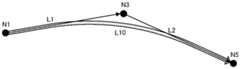
图5A~图5C是用于说明本实施方式的AR路径的形成的图。图中的附图标记N1~N5表示路径区间内的节点。由此,在以往的AR路径的形成处理中,形成按N1→N2→N3→N4→N5依次连上的AR路径。5A to 5C are diagrams for explaining the formation of the AR path according to the present embodiment. Reference numerals N1 to N5 in the figure represent nodes within the path section. As a result, in the conventional AR path formation process, the AR paths connected in the order of N1→N2→N3→N4→N5 are formed.
相对于此,在本实施方式的AR路径的形成处理中,首先,判断N1~N5的区间是否为直线区间,在判断为是直线区间的情况下,以将连结区间的开始节点N1和结束节点N5的直线L0作为AR路径的方式形成AR路径并进行显示。相对于此,在判断为不是直线区间的情况下,进行后述的分割处理或弯道修正处理。On the other hand, in the AR route forming process of the present embodiment, first, it is determined whether or not the sections N1 to N5 are straight sections, and when it is determined that the sections are straight sections, the start node N1 and the end node of the section are connected by The straight line L0 of N5 forms an AR path and displays it as an AR path. On the other hand, when it is judged that it is not a straight section, a division process or a curve correction process to be described later is performed.
具体地进行说明。在本实施方式的AR路径的形成处理中,首先,如图5A所示,形成连结作为判断是否为直线区间的判断对象的路径区间内的区间开始节点N1和区间结束节点N5的直线L0。It demonstrates concretely. In the AR route formation process of the present embodiment, first, as shown in FIG. 5A , a straight line L0 connecting the section start node N1 and the section end node N5 in the route section that is the determination target of whether the straight section is determined is formed.
接着,计算直线L0与路径区间内包含的其他节点N2、N3、N4之间的距离h2、h3、h4。Next, distances h2, h3, and h4 between the straight line L0 and the other nodes N2, N3, and N4 included in the path section are calculated.
接着,AR路径形成部111将距离h2、h3、h4与规定的阈值进行比较。在距离h2、h3、h4均为阈值以下的情况下,AR路径形成部111将节点N1~N5的区间以一条直线L0连结而制成AR路径。相对于此,当在距离h2、h3、h4之中包含比阈值大的距离的情况下,AR路径形成部111以距离最大的节点为分割点将路径区间分割。在图5A~图5C所示的例子的情况下,距节点N3的距离h3最大,因此以节点N3为分割点将路径区间分割。Next, the AR
接着,如图5B所示,将分割点设为区间的结束点及开始点,与上述同样地,重复进行判断是否为直线区间的判断处理。具体而言,形成连结路径区间内的区间开始节点N1和区间结束节点N3的直线L1。同样地,形成连结路径区间内的区间开始节点N3和区间结束节点N5的直线L2。接着,计算直线L1与路径区间内包含的其他节点N2之间的距离h2。同样地,计算直线L2与路径区间内包含的其他节点N4之间的距离h4。接着,将距离h2与阈值进行比较。同样地,将距离h4与阈值进行比较。在图5A~图5C的例子中,距离h2比阈值小,因此如图5C所示,将节点N1~N3的区间以一条直线L1连结而制成AR路径。同样地,距离h4比阈值小,因此如图5C所示,将节点N3~N5的区间以一条直线L2连结而制成AR路径。Next, as shown in FIG. 5B , the division points are set as the end point and the start point of the section, and the determination process for determining whether or not the section is a straight line is repeated in the same manner as described above. Specifically, a straight line L1 connecting the section start node N1 and the section end node N3 in the path section is formed. Similarly, a straight line L2 connecting the section start node N3 and the section end node N5 in the path section is formed. Next, the distance h2 between the straight line L1 and the other node N2 included in the path section is calculated. Similarly, the distance h4 between the straight line L2 and the other node N4 included in the path section is calculated. Next, the distance h2 is compared with a threshold value. Likewise, the distance h4 is compared to the threshold. In the examples of FIGS. 5A to 5C , since the distance h2 is smaller than the threshold value, as shown in FIG. 5C , the section between the nodes N1 to N3 is connected by a straight line L1 to form an AR route. Similarly, since the distance h4 is smaller than the threshold value, as shown in FIG. 5C , the section between the nodes N3 to N5 is connected by a straight line L2 to form an AR route.
总之,本实施方式的直线的修正处理,是将未从连结区间的开始节点和结束节点的直线明显脱离的节点除去(忽略),而制成直线的处理。通过上述构成,能够防止由节点的坐标的设定方式所引起的、不自然的AR路径的弯折。例如,能够防止以下这种不理想情况:尽管实际上是直线道路,但由于节点的坐标被设定为交叉路口中央位置的坐标,从而导致AR路径在每个交叉路口处都有一些弯折。In short, the straight line correction process of the present embodiment is a process of removing (ignoring) nodes that are not significantly separated from the straight line connecting the start node and the end node of the section to form a straight line. With the above-described configuration, it is possible to prevent the AR path from bending unnaturally due to how the coordinates of the nodes are set. For example, it is possible to prevent an undesirable situation where the AR path has some bends at each intersection because the coordinates of the nodes are set to the coordinates of the center of the intersection despite the fact that it is a straight road.
图6表示未适用本实施方式的直线修正处理的情况下的AR路径的显示例。根据该图可知,尽管是直线道路,但AR路径在交叉路口处有一些弯折。图7表示适用了本实施方式的直线修正处理的情况下的AR路径的显示例。根据该图可知,消除了交叉路口处的AR路径的弯折。FIG. 6 shows a display example of the AR route when the straight line correction process of the present embodiment is not applied. As can be seen from this figure, despite being a straight road, the AR route has some bends at the intersection. FIG. 7 shows a display example of the AR route when the straight line correction processing of the present embodiment is applied. As can be seen from this figure, the bending of the AR route at the intersection is eliminated.
图8是表示本实施方式的AR路径的直线修正处理的流程的流程图。FIG. 8 is a flowchart showing the flow of the straight line correction processing of the AR path according to the present embodiment.
AR路径形成部111首先在步骤S1中,计算连结开始节点和结束节点的直线与区间内包含的其他节点之间的距离h。也就是说,计算图5A的例子中的、连结区间开始节点N1和区间结束节点N5的直线L0与区间内包含的其他节点N2、N3、N4之间的距离h2、h3、h4。First, in step S1 , the AR
AR路径形成部111在接下来的步骤S2中,计算是否所有距离h2、h3、h4均在阈值以内。当在步骤S2中得到了肯定结果的情况下(步骤S2:“是”),转移至步骤S3,并将该区间判断为是直线区间而形成AR路径。也就是说,若是在图5A的例子的情况下,则将直线L0设为AR路径。In the next step S2, the AR
相对于此,当在步骤S2得到了否定结果的情况下(步骤S2:“否”),转移至步骤S4,以距离h最大的节点为分割点将区间分割。也就是说,若是在图5B的例子的情况下,则以节点N3为分割点将路径区间分割。AR路径形成部111在步骤S4的处理之后,再次返回到步骤S1。该步骤S1的处理相当于计算图5B的例子中的距离h2、h4的处理。On the other hand, when a negative result is obtained in step S2 (step S2: NO), the process proceeds to step S4, and the section is divided with the node having the largest distance h as the dividing point. That is, in the case of the example of FIG. 5B , the route section is divided with the node N3 as the dividing point. After the process of step S4, the AR
这样,AR路径形成部111递归地重复步骤S1→S2→S4→S1的处理,直至在步骤S2中得到肯定结果为止,从而不断地将区间分割,直至不存在距离在阈值以上的节点。并且,在距离在阈值以上的节点不再存在时,将该区间判断为是直线区间并进行步骤S3的处理,以在直线区间内形成一条直线的AR路径。In this way, the AR
<2-2>曲线插值<2-2> Curve interpolation
本实施方式的AR路径形成部111对判断为不是直线区间的路径区间进行曲线插值。The AR
例如,对在进行了项目<2-1>中所说明的那样的直线的修正(也可以称为“直线的平滑化”)之后不是直线区间的区间,进行图9所示那样的曲线插值。在图9的例子中,直线L1与直线L2经由作为分割点的节点N3而弯折地连接,因此N1~N3~N5的区间不是直线区间。实际上,在多数情况下,N1~N3~N5的区间并不是弯折的道路,而是弯道。考虑到这点,AR路径形成部111通过对N1~N3~N5的区间进行曲线插值来形成曲线L10,并将该曲线L10作为AR路径输出。For example, curve interpolation as shown in FIG. 9 is performed for a section that is not a straight section after the straight line correction (which may also be referred to as “straight line smoothing”) as described in the item <2-1> is performed. In the example of FIG. 9, since the straight line L1 and the straight line L2 are connected by bending through the node N3 which is a dividing point, the section of N1-N3-N5 is not a straight line section. In fact, in many cases, the sections N1 to N3 to N5 are not curved roads but curves. Taking this into consideration, the AR
这时,AR路径形成部111以该区间中包含的节点为控制点进行曲线插值。在图9的例子中,通过进行以节点N1、N3、N5为控制点的曲线插值,来形成曲线L10。At this time, the AR
在此,节点不一定是以构成圆润的曲线的方式配置的,有时若以通过所有节点的方式进行曲线插值,则会成为存在变形的曲线形状。考虑到这点,在本实施方式中,通过进行基于B样条曲线的插值,来形成无变形的曲线L10。但是,曲线插值不限于基于B样条曲线的插值。Here, the nodes are not necessarily arranged so as to form a rounded curve, and if the curve interpolation is performed so as to pass through all the nodes, a deformed curve shape may be obtained. Taking this into consideration, in the present embodiment, the curve L10 without deformation is formed by performing interpolation based on the B-spline curve. However, curve interpolation is not limited to interpolation based on B-splines.
此外,在此,对以下情况进行了叙述,即,对在进行了项目<2-1>中所说明的那样的直线的修正之后不是直线区间的区间,进行曲线插值的情况,但不限于此,总而言之,只要对判断为不是直线区间的路径区间,以该区间中包含的节点为控制点进行曲线插值,并将曲线插值后的曲线作为AR路径来输出即可。In addition, the case where curve interpolation is performed on a section that is not a straight section after the straight line correction as described in the item <2-1> has been performed has been described here, but the present invention is not limited to this case. , in a word, it is only necessary to perform curve interpolation on the route interval determined not to be a straight interval, using the nodes included in the interval as control points, and output the curve after curve interpolation as the AR route.
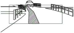
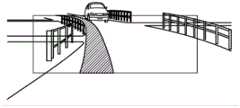
图10表示未适用本实施方式的曲线插值处理的情况下的AR路径的显示例。根据该图可知,尽管实际的道路是弯道,但AR路径成为折线。图11表示适用了本实施方式的曲线插值处理的情况下的AR路径的显示例。根据该图可知,能够显示由沿着弯道的曲线形状构成的AR路径。FIG. 10 shows a display example of an AR route when the curve interpolation process of the present embodiment is not applied. As can be seen from this figure, although the actual road is a curve, the AR route is a polyline. FIG. 11 shows a display example of an AR route when the curve interpolation process of the present embodiment is applied. As can be seen from this figure, an AR route composed of a curved shape along a curve can be displayed.
<2-3>基于车道信息的AR路径的移位处理<2-3> Shift processing of AR path based on lane information
如上所述,AR路径是基于道路地图数据中包含的节点和路段制成的。但是,如发明要解决的问题的项目中也已经叙述的那样,节点和路段中包含的坐标信息在较多的情况下为道路的中央位置的坐标,所以若直接使用该信息来形成AR路径,则有时会显示存在不协调感的AR路径。尤其是,在交叉路口或分支地点等多个道路相交的位置,显示存在不协调感的AR路径的可能性较高。As mentioned above, AR routes are made based on nodes and road segments contained in road map data. However, as already described in the item of the problem to be solved by the invention, the coordinate information included in the nodes and links is often the coordinates of the center position of the road. Therefore, if this information is used as it is to form an AR route, In some cases, an AR path with a sense of incongruity is displayed. In particular, at a position where a plurality of roads intersect, such as an intersection or a branch point, there is a high possibility that an AR route with a sense of incongruity is displayed.
考虑到这点,在本实施方式中,通过基于车道信息,将道路地图数据中包含的节点坐标向本车预定要行驶的车道侧移位,来形成AR路径。由此,能够基于车道信息,显示移位到本车行驶的车道侧的、没有不协调感的AR路径。顺便说明一下,AR路径是将节点连结而形成的,因此使节点坐标移位等于使AR路径移位。由此,在以下的记述中,也可以将“使节点坐标移位”替换为“使AR路径移位”,反之,也可以将“使AR路径移位”替换为“使节点坐标移位”。Taking this into consideration, in the present embodiment, based on the lane information, the AR route is formed by shifting the node coordinates included in the road map data to the side of the lane where the host vehicle is scheduled to travel. Thereby, based on the lane information, it is possible to display an AR route that is shifted to the side of the lane on which the vehicle is traveling and does not feel uncomfortable. By the way, the AR path is formed by connecting nodes, so shifting the coordinates of the nodes is equivalent to shifting the AR path. Therefore, in the following description, "shift the node coordinates" may be replaced by "shift the AR path", and conversely, "shift the AR path" may be replaced by "shift the node coordinates" .
图12A、图12B是用于说明以往进行的AR路径的显示的图。如图12A所示,设想本车在具有中心线的、单侧有一个车道的道路上行驶,并在前方的交叉路口右转的情况。这时,节点N1~N4的坐标被设为中心线上的坐标。FIG. 12A and FIG. 12B are diagrams for explaining the display of the AR route performed in the past. As shown in FIG. 12A , it is assumed that the host vehicle is traveling on a road having a center line and one lane on one side, and turns right at the intersection ahead. At this time, the coordinates of the nodes N1 to N4 are set as the coordinates on the center line.
图12B是表示以图12A的节点N1~N4为基础形成并显示的AR路径的图。根据图12B可知,以往的AR路径中,开始点是与本车的行驶位置相匹配的,因此能以没有不协调感的方式对本车的前方进行显示,但通过交叉路口后的部分会处于中心线上。也就是说,AR路径从实际的预定要行驶的车道向中心线方向错开。FIG. 12B is a diagram showing AR paths formed and displayed based on the nodes N1 to N4 of FIG. 12A . As can be seen from FIG. 12B , in the conventional AR route, the starting point matches the driving position of the vehicle, so the front of the vehicle can be displayed without a sense of incongruity, but the part after passing through the intersection is in the center on-line. That is, the AR route is shifted in the direction of the center line from the actual intended lane to travel.
图13A、图13B是用于说明本实施方式的AR路径的显示的图。在本实施方式中,如图13A所示,通过使中心线上的节点N1、N2、N3、N4的坐标向本车预定要行驶的车道侧移位,来计算节点N1’、N2’、N3’、N4’,并使用该节点N1’、N2’、N3’、N4’形成AR路径并进行显示。13A and 13B are diagrams for explaining the display of the AR route according to the present embodiment. In this embodiment, as shown in FIG. 13A , the nodes N1 ′, N2 ′, and N3 are calculated by shifting the coordinates of the nodes N1 , N2 , N3 , and N4 on the center line to the side of the lane where the vehicle is expected to travel. ', N4', and use the nodes N1', N2', N3', N4' to form an AR path and display it.
图13B是表示以图13A的节点N1’、N2’、N3’、N4’为基础形成,并被显示的AR路径的图。根据图13B可知,本实施方式的AR路径的通过交叉路口后的部分也显示于本车预定要行驶的车道上。由此,能够显示没有不协调感的AR路径。Fig. 13B is a diagram showing an AR route formed on the basis of nodes N1', N2', N3', and N4' shown in Fig. 13A and displayed. As can be seen from FIG. 13B , the part of the AR route in the present embodiment after passing through the intersection is also displayed on the lane where the vehicle is scheduled to travel. Thereby, it is possible to display an AR route without a sense of incongruity.
在此,举出本实施方式的具体的AR路径的移位的例子。Here, an example of a specific AR path shift in the present embodiment is given.
在单侧有三个车道且预定要行驶的车道是最靠左的车道的情况下,使节点位置向本车的车道侧移位如下的量,即,[车道宽度(例如3.25m)×(车道数量(该例子中为3个)-0.5)]。该处理是与节点设定于中心线上的情况对应的处理。When there are three lanes on one side and the lane to be driven is the leftmost lane, the node position is shifted to the lane side of the vehicle by the following amount, that is, [lane width (for example, 3.25m) × (lane width) number (3 in this example) - 0.5)]. This processing corresponds to the case where the node is set on the center line.
这样,在本实施方式的AR路径的移位处理中,使设定于道路的中央的节点向本车预定要行驶的车道侧移位。在本实施方式中,使AR路径移位至本车预定要行驶的车道的中央位置。In this way, in the AR route shift processing of the present embodiment, the node set in the center of the road is shifted to the side of the lane where the host vehicle is scheduled to travel. In the present embodiment, the AR route is shifted to the center of the lane in which the host vehicle is to travel.
在本实施方式的AR路径的移位处理中,尤其是,基于作为左转目的地或右转目的地的道路的车道信息、或作为分支目的地的道路的车道信息,使左转目的地、右转目的地或分支目的地的AR路径移位,因此能够减少左转目的地、右转目的地或分支目的地处的AR路径的不协调感。In the AR route shift processing of the present embodiment, in particular, the left-turn destination, Since the AR route at the right turn destination or the branch destination is shifted, the sense of incongruity of the AR route at the left turn destination, the right turn destination, or the branch destination can be reduced.
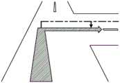
接着,使用图14A、图14B,对本实施方式的AR路径的移位处理的效果进行说明。Next, the effect of the shift processing of the AR path according to the present embodiment will be described with reference to FIGS. 14A and 14B .
图14A、图14B是表示在前方的交叉路口进行左转的情况下的AR路径显示的图。图14A表示未使AR路径移位的例子,图14B表示适用了本实施方式的AR路径的移位处理的例子。比较这些图可知,图14A的AR路径的通过交叉路口后的部分显示于并非本车预定要行驶的道路的中央位置附近,相对于此,图14B的AR路径中,通过交叉路口后的部分也会以没有不协调感的方式显示于本车预定要行驶的车道。14A and 14B are diagrams showing AR route display when a left turn is made at an intersection ahead. FIG. 14A shows an example in which the AR path is not shifted, and FIG. 14B shows an example in which the AR path shift processing according to the present embodiment is applied. Comparing these figures, it can be seen that the part of the AR route in FIG. 14A after passing through the intersection is not displayed near the center of the road on which the vehicle is intended to travel. On the other hand, in the AR route in FIG. 14B , the part after passing through the intersection is also displayed. It will be displayed in the lane where the vehicle is scheduled to travel without any incongruity.
这样,若进行本实施方式的AR路径的移位处理,则即使交叉路口的节点位置从行驶车道的延长线上向左或向右错开地配置,也能够显示沿着预定要行驶的车道的、没有不协调感的AR路径。In this way, by performing the AR route shift processing according to the present embodiment, even if the node positions of the intersection are shifted to the left or right from the extension line of the driving lane, it is possible to display the information along the lane to be traveled. AR path without incongruity.
<3>概括<3> Summary
如以上说明的那样,根据本实施方式,如项目<2-3>中所说明的那样,基于车道信息,使道路地图数据中包含的节点信息向本车预定要行驶的车道侧移位,由此形成AR路径,因此,能够消除在交叉路口或分支地点等多个道路相交的位置,AR路径从预定要行驶的路径大幅错开之类的不理想情况,从而能够显示切合于本车预定要行驶的路径的形状的、没有不协调感的AR路径。As described above, according to the present embodiment, as described in the item <2-3>, based on the lane information, the node information included in the road map data is shifted to the side of the lane where the vehicle is expected to travel, and the This forms an AR route. Therefore, it is possible to eliminate the undesired situation where the AR route is greatly deviated from the route planned to be traveled at a position where a plurality of roads intersect, such as an intersection or branch point. The shape of the path is an AR path without a sense of incongruity.
上述实施方式不过是表示实施本发明的时候的具体化的一例,并非限定地解释本发明的技术的范围。即,本发明能够在不脱离其要旨或者其主要特征的范围内以各种形式实施。The above-described embodiment is merely an example of the implementation of the present invention, and is not intended to limit the technical scope of the present invention. That is, the present invention can be implemented in various forms without departing from the gist or the main characteristics thereof.
在上述的实施方式中,针对将本发明的显示装置适用于车载用的HUD的情况进行了叙述,但不限于此,总而言之,本发明的显示装置能够广泛适用于以在从用户角度看到的实像上重叠的方式显示作为虚像的AR路径的显示系统及装置。In the above-mentioned embodiments, the case where the display device of the present invention is applied to a HUD for in-vehicle use has been described, but the present invention is not limited thereto. A display system and device that displays an AR path as a virtual image by superimposing it on a real image.
工业实用性Industrial Applicability
本发明的显示系统及显示装置例如适用于具备了车载用的HUD的系统。The display system and the display device of the present invention are suitable for, for example, a system including an in-vehicle HUD.
Claims (5)
Translated fromChineseApplications Claiming Priority (2)
| Application Number | Priority Date | Filing Date | Title |
|---|---|---|---|
| JP2019061464AJP7365594B2 (en) | 2019-03-27 | 2019-03-27 | display system |
| JP2019-061464 | 2019-03-27 |
Publications (2)
| Publication Number | Publication Date |
|---|---|
| CN111750893Atrue CN111750893A (en) | 2020-10-09 |
| CN111750893B CN111750893B (en) | 2024-10-01 |
Family
ID=72606195
Family Applications (1)
| Application Number | Title | Priority Date | Filing Date |
|---|---|---|---|
| CN202010221208.1AActiveCN111750893B (en) | 2019-03-27 | 2020-03-26 | Display system and display device |
Country Status (4)
| Country | Link |
|---|---|
| US (1) | US11514785B2 (en) |
| JP (1) | JP7365594B2 (en) |
| CN (1) | CN111750893B (en) |
| DE (1) | DE102020108343B4 (en) |
Families Citing this family (7)
| Publication number | Priority date | Publication date | Assignee | Title |
|---|---|---|---|---|
| WO2019164514A1 (en)* | 2018-02-23 | 2019-08-29 | Google Llc | Transitioning between map view and augmented reality view |
| US11555711B2 (en)* | 2020-04-11 | 2023-01-17 | Harman Becker Automotive Systems Gmbh | Systems and methods for augmented reality in a vehicle |
| JP7447842B2 (en)* | 2021-02-15 | 2024-03-12 | 株式会社Soken | Vehicle display control device, vehicle display control method |
| US11845429B2 (en)* | 2021-09-30 | 2023-12-19 | GM Global Technology Operations LLC | Localizing and updating a map using interpolated lane edge data |
| US11987251B2 (en) | 2021-11-15 | 2024-05-21 | GM Global Technology Operations LLC | Adaptive rationalizer for vehicle perception systems toward robust automated driving control |
| JP7694479B2 (en)* | 2022-06-29 | 2025-06-18 | トヨタ自動車株式会社 | Vehicle display control device, vehicle display control system, vehicle, vehicle display control method and program |
| JP2024159291A (en)* | 2023-04-28 | 2024-11-08 | パナソニックオートモーティブシステムズ株式会社 | Display device, display method, and program |
Citations (7)
| Publication number | Priority date | Publication date | Assignee | Title |
|---|---|---|---|---|
| JPH07257228A (en)* | 1994-03-18 | 1995-10-09 | Nissan Motor Co Ltd | Vehicle display |
| JP2013096713A (en)* | 2011-10-28 | 2013-05-20 | Alpine Electronics Inc | Navigation device |
| KR20150054022A (en)* | 2013-11-08 | 2015-05-20 | 현대오트론 주식회사 | Apparatus for displaying lane changing information using head-up display and method thereof |
| JP2016090344A (en)* | 2014-10-31 | 2016-05-23 | アイシン・エィ・ダブリュ株式会社 | Navigation device and navigation program |
| CN108318049A (en)* | 2017-01-16 | 2018-07-24 | 安波福电子(苏州)有限公司 | A kind of vehicle-mounted high-precision track navigation system |
| JP2018127204A (en)* | 2017-02-08 | 2018-08-16 | 株式会社デンソー | Display control device for vehicle |
| JP2018173399A (en)* | 2017-03-31 | 2018-11-08 | アイシン・エィ・ダブリュ株式会社 | Display device and computer program |
Family Cites Families (6)
| Publication number | Priority date | Publication date | Assignee | Title |
|---|---|---|---|---|
| JP4994256B2 (en)* | 2008-01-28 | 2012-08-08 | 株式会社ジオ技術研究所 | Data structure of route guidance database |
| US9677898B2 (en)* | 2014-06-17 | 2017-06-13 | Think Ware Corporation | Electronic apparatus and control method thereof |
| KR102123844B1 (en) | 2014-07-18 | 2020-06-18 | 팅크웨어(주) | Electronic apparatus, control method of electronic apparatus and computer readable recording medium |
| JP6569999B2 (en) | 2016-09-14 | 2019-09-04 | パナソニックIpマネジメント株式会社 | Display device |
| JP6601441B2 (en) | 2017-02-28 | 2019-11-06 | 株式会社デンソー | Display control apparatus and display control method |
| JP6758516B2 (en)* | 2017-09-08 | 2020-09-23 | 三菱電機株式会社 | Driving support device and driving support method |
- 2019
- 2019-03-27JPJP2019061464Apatent/JP7365594B2/enactiveActive
- 2020
- 2020-03-25USUS16/829,504patent/US11514785B2/enactiveActive
- 2020-03-26CNCN202010221208.1Apatent/CN111750893B/enactiveActive
- 2020-03-26DEDE102020108343.2Apatent/DE102020108343B4/enactiveActive
Patent Citations (7)
| Publication number | Priority date | Publication date | Assignee | Title |
|---|---|---|---|---|
| JPH07257228A (en)* | 1994-03-18 | 1995-10-09 | Nissan Motor Co Ltd | Vehicle display |
| JP2013096713A (en)* | 2011-10-28 | 2013-05-20 | Alpine Electronics Inc | Navigation device |
| KR20150054022A (en)* | 2013-11-08 | 2015-05-20 | 현대오트론 주식회사 | Apparatus for displaying lane changing information using head-up display and method thereof |
| JP2016090344A (en)* | 2014-10-31 | 2016-05-23 | アイシン・エィ・ダブリュ株式会社 | Navigation device and navigation program |
| CN108318049A (en)* | 2017-01-16 | 2018-07-24 | 安波福电子(苏州)有限公司 | A kind of vehicle-mounted high-precision track navigation system |
| JP2018127204A (en)* | 2017-02-08 | 2018-08-16 | 株式会社デンソー | Display control device for vehicle |
| JP2018173399A (en)* | 2017-03-31 | 2018-11-08 | アイシン・エィ・ダブリュ株式会社 | Display device and computer program |
Also Published As
| Publication number | Publication date |
|---|---|
| DE102020108343B4 (en) | 2024-05-29 |
| JP7365594B2 (en) | 2023-10-20 |
| DE102020108343A1 (en) | 2020-10-15 |
| US11514785B2 (en) | 2022-11-29 |
| JP2020159953A (en) | 2020-10-01 |
| CN111750893B (en) | 2024-10-01 |
| US20200312146A1 (en) | 2020-10-01 |
Similar Documents
| Publication | Publication Date | Title |
|---|---|---|
| CN111750893A (en) | Display system and display device | |
| KR101558353B1 (en) | Head-up display apparatus for vehicle using aumented reality | |
| JP5810842B2 (en) | Lane guidance display system, method and program | |
| JP5708449B2 (en) | Lane guidance display system, method and program | |
| US7920966B2 (en) | Navigation apparatuses, methods, and programs | |
| JP6695049B2 (en) | Display device and display control method | |
| JP5810843B2 (en) | Lane guidance display system, method and program | |
| RU2677122C1 (en) | Vehicle displaying device | |
| KR20120113579A (en) | Apparatus and method for displaying road guide information on the windshield | |
| CN109927552A (en) | Display apparatus | |
| JP7416114B2 (en) | Display control device and display control program | |
| WO2018173512A1 (en) | Display control device for vehicle and display unit for vehicle | |
| JP2015049221A (en) | Route guide display system, method, and program | |
| CN109470261B (en) | Head-up display system | |
| CN111751993B (en) | Display system and display device | |
| JP5733195B2 (en) | Lane guidance display system, method and program | |
| US10730434B2 (en) | Vehicular display control device, vehicular display system, vehicular display control method, and non-transitory storage medium | |
| CN114287025A (en) | Driving assistance method and driving assistance device | |
| JP5906988B2 (en) | Road shape guidance system, method and program | |
| JP6448806B2 (en) | Display control device, display device, and display control method | |
| JP2021133874A (en) | Display control device, head-up display device and method | |
| KR101637298B1 (en) | Head-up display apparatus for vehicle using aumented reality | |
| JP5983498B2 (en) | Intersection guidance system, method and program | |
| JP5733196B2 (en) | Lane guidance display system, method and program |
Legal Events
| Date | Code | Title | Description |
|---|---|---|---|
| PB01 | Publication | ||
| PB01 | Publication | ||
| SE01 | Entry into force of request for substantive examination | ||
| SE01 | Entry into force of request for substantive examination | ||
| TA01 | Transfer of patent application right | Effective date of registration:20240409 Address after:Kanagawa Prefecture, Japan Applicant after:Panasonic Automotive Electronic Systems Co.,Ltd. Country or region after:Japan Address before:Osaka, Japan Applicant before:PANASONIC INTELLECTUAL PROPERTY MANAGEMENT Co.,Ltd. Country or region before:Japan | |
| TA01 | Transfer of patent application right | ||
| GR01 | Patent grant | ||
| GR01 | Patent grant |