CN111745640B - Object detection method, object detection device, and robot system - Google Patents
Object detection method, object detection device, and robot systemDownload PDFInfo
- Publication number
- CN111745640B CN111745640BCN202010223866.4ACN202010223866ACN111745640BCN 111745640 BCN111745640 BCN 111745640BCN 202010223866 ACN202010223866 ACN 202010223866ACN 111745640 BCN111745640 BCN 111745640B
- Authority
- CN
- China
- Prior art keywords
- posture
- target
- unit
- image
- holding
- Prior art date
- Legal status (The legal status is an assumption and is not a legal conclusion. Google has not performed a legal analysis and makes no representation as to the accuracy of the status listed.)
- Active
Links
Images


Classifications
- B—PERFORMING OPERATIONS; TRANSPORTING
- B25—HAND TOOLS; PORTABLE POWER-DRIVEN TOOLS; MANIPULATORS
- B25J—MANIPULATORS; CHAMBERS PROVIDED WITH MANIPULATION DEVICES
- B25J9/00—Programme-controlled manipulators
- B25J9/16—Programme controls
- B25J9/1656—Programme controls characterised by programming, planning systems for manipulators
- B25J9/1671—Programme controls characterised by programming, planning systems for manipulators characterised by simulation, either to verify existing program or to create and verify new program, CAD/CAM oriented, graphic oriented programming systems
- B—PERFORMING OPERATIONS; TRANSPORTING
- B25—HAND TOOLS; PORTABLE POWER-DRIVEN TOOLS; MANIPULATORS
- B25J—MANIPULATORS; CHAMBERS PROVIDED WITH MANIPULATION DEVICES
- B25J9/00—Programme-controlled manipulators
- B25J9/16—Programme controls
- B25J9/1679—Programme controls characterised by the tasks executed
- B—PERFORMING OPERATIONS; TRANSPORTING
- B25—HAND TOOLS; PORTABLE POWER-DRIVEN TOOLS; MANIPULATORS
- B25J—MANIPULATORS; CHAMBERS PROVIDED WITH MANIPULATION DEVICES
- B25J19/00—Accessories fitted to manipulators, e.g. for monitoring, for viewing; Safety devices combined with or specially adapted for use in connection with manipulators
- B25J19/02—Sensing devices
- B25J19/021—Optical sensing devices
- B25J19/023—Optical sensing devices including video camera means
- B—PERFORMING OPERATIONS; TRANSPORTING
- B25—HAND TOOLS; PORTABLE POWER-DRIVEN TOOLS; MANIPULATORS
- B25J—MANIPULATORS; CHAMBERS PROVIDED WITH MANIPULATION DEVICES
- B25J9/00—Programme-controlled manipulators
- B25J9/16—Programme controls
- B25J9/1602—Programme controls characterised by the control system, structure, architecture
- B—PERFORMING OPERATIONS; TRANSPORTING
- B25—HAND TOOLS; PORTABLE POWER-DRIVEN TOOLS; MANIPULATORS
- B25J—MANIPULATORS; CHAMBERS PROVIDED WITH MANIPULATION DEVICES
- B25J9/00—Programme-controlled manipulators
- B25J9/16—Programme controls
- B25J9/1656—Programme controls characterised by programming, planning systems for manipulators
- B25J9/1664—Programme controls characterised by programming, planning systems for manipulators characterised by motion, path, trajectory planning
- B—PERFORMING OPERATIONS; TRANSPORTING
- B25—HAND TOOLS; PORTABLE POWER-DRIVEN TOOLS; MANIPULATORS
- B25J—MANIPULATORS; CHAMBERS PROVIDED WITH MANIPULATION DEVICES
- B25J9/00—Programme-controlled manipulators
- B25J9/16—Programme controls
- B25J9/1694—Programme controls characterised by use of sensors other than normal servo-feedback from position, speed or acceleration sensors, perception control, multi-sensor controlled systems, sensor fusion
- B25J9/1697—Vision controlled systems
- G—PHYSICS
- G06—COMPUTING OR CALCULATING; COUNTING
- G06F—ELECTRIC DIGITAL DATA PROCESSING
- G06F18/00—Pattern recognition
- G06F18/20—Analysing
- G06F18/24—Classification techniques
- G06F18/241—Classification techniques relating to the classification model, e.g. parametric or non-parametric approaches
- G06F18/2415—Classification techniques relating to the classification model, e.g. parametric or non-parametric approaches based on parametric or probabilistic models, e.g. based on likelihood ratio or false acceptance rate versus a false rejection rate
- G06F18/24155—Bayesian classification
- G—PHYSICS
- G06—COMPUTING OR CALCULATING; COUNTING
- G06N—COMPUTING ARRANGEMENTS BASED ON SPECIFIC COMPUTATIONAL MODELS
- G06N20/00—Machine learning
- G—PHYSICS
- G06—COMPUTING OR CALCULATING; COUNTING
- G06T—IMAGE DATA PROCESSING OR GENERATION, IN GENERAL
- G06T1/00—General purpose image data processing
- G06T1/0014—Image feed-back for automatic industrial control, e.g. robot with camera
- G—PHYSICS
- G06—COMPUTING OR CALCULATING; COUNTING
- G06V—IMAGE OR VIDEO RECOGNITION OR UNDERSTANDING
- G06V10/00—Arrangements for image or video recognition or understanding
- G06V10/70—Arrangements for image or video recognition or understanding using pattern recognition or machine learning
- G06V10/77—Processing image or video features in feature spaces; using data integration or data reduction, e.g. principal component analysis [PCA] or independent component analysis [ICA] or self-organising maps [SOM]; Blind source separation
- G06V10/776—Validation; Performance evaluation
- G—PHYSICS
- G06—COMPUTING OR CALCULATING; COUNTING
- G06V—IMAGE OR VIDEO RECOGNITION OR UNDERSTANDING
- G06V20/00—Scenes; Scene-specific elements
- G06V20/10—Terrestrial scenes
- G—PHYSICS
- G06—COMPUTING OR CALCULATING; COUNTING
- G06V—IMAGE OR VIDEO RECOGNITION OR UNDERSTANDING
- G06V20/00—Scenes; Scene-specific elements
- G06V20/20—Scenes; Scene-specific elements in augmented reality scenes
- G—PHYSICS
- G06—COMPUTING OR CALCULATING; COUNTING
- G06V—IMAGE OR VIDEO RECOGNITION OR UNDERSTANDING
- G06V20/00—Scenes; Scene-specific elements
- G06V20/50—Context or environment of the image
- G06V20/56—Context or environment of the image exterior to a vehicle by using sensors mounted on the vehicle
- G06V20/58—Recognition of moving objects or obstacles, e.g. vehicles or pedestrians; Recognition of traffic objects, e.g. traffic signs, traffic lights or roads
- G—PHYSICS
- G06—COMPUTING OR CALCULATING; COUNTING
- G06V—IMAGE OR VIDEO RECOGNITION OR UNDERSTANDING
- G06V20/00—Scenes; Scene-specific elements
- G06V20/60—Type of objects
- G06V20/64—Three-dimensional objects
- G06V20/653—Three-dimensional objects by matching three-dimensional models, e.g. conformal mapping of Riemann surfaces
- G—PHYSICS
- G06—COMPUTING OR CALCULATING; COUNTING
- G06V—IMAGE OR VIDEO RECOGNITION OR UNDERSTANDING
- G06V40/00—Recognition of biometric, human-related or animal-related patterns in image or video data
- G06V40/20—Movements or behaviour, e.g. gesture recognition
- G—PHYSICS
- G05—CONTROLLING; REGULATING
- G05B—CONTROL OR REGULATING SYSTEMS IN GENERAL; FUNCTIONAL ELEMENTS OF SUCH SYSTEMS; MONITORING OR TESTING ARRANGEMENTS FOR SUCH SYSTEMS OR ELEMENTS
- G05B2219/00—Program-control systems
- G05B2219/30—Nc systems
- G05B2219/39—Robotics, robotics to robotics hand
- G05B2219/39514—Stability of grasped objects
- G—PHYSICS
- G05—CONTROLLING; REGULATING
- G05B—CONTROL OR REGULATING SYSTEMS IN GENERAL; FUNCTIONAL ELEMENTS OF SUCH SYSTEMS; MONITORING OR TESTING ARRANGEMENTS FOR SUCH SYSTEMS OR ELEMENTS
- G05B2219/00—Program-control systems
- G05B2219/30—Nc systems
- G05B2219/40—Robotics, robotics mapping to robotics vision
- G05B2219/40053—Pick 3-D object from pile of objects
- G—PHYSICS
- G05—CONTROLLING; REGULATING
- G05B—CONTROL OR REGULATING SYSTEMS IN GENERAL; FUNCTIONAL ELEMENTS OF SUCH SYSTEMS; MONITORING OR TESTING ARRANGEMENTS FOR SUCH SYSTEMS OR ELEMENTS
- G05B2219/00—Program-control systems
- G05B2219/30—Nc systems
- G05B2219/40—Robotics, robotics mapping to robotics vision
- G05B2219/40584—Camera, non-contact sensor mounted on wrist, indep from gripper
- G—PHYSICS
- G06—COMPUTING OR CALCULATING; COUNTING
- G06V—IMAGE OR VIDEO RECOGNITION OR UNDERSTANDING
- G06V2201/00—Indexing scheme relating to image or video recognition or understanding
- G06V2201/06—Recognition of objects for industrial automation
- G—PHYSICS
- G06—COMPUTING OR CALCULATING; COUNTING
- G06V—IMAGE OR VIDEO RECOGNITION OR UNDERSTANDING
- G06V2201/00—Indexing scheme relating to image or video recognition or understanding
- G06V2201/07—Target detection
Landscapes
- Engineering & Computer Science (AREA)
- Theoretical Computer Science (AREA)
- Physics & Mathematics (AREA)
- Robotics (AREA)
- General Physics & Mathematics (AREA)
- Mechanical Engineering (AREA)
- Multimedia (AREA)
- Software Systems (AREA)
- Computer Vision & Pattern Recognition (AREA)
- Evolutionary Computation (AREA)
- Artificial Intelligence (AREA)
- Data Mining & Analysis (AREA)
- Health & Medical Sciences (AREA)
- Computing Systems (AREA)
- General Health & Medical Sciences (AREA)
- Medical Informatics (AREA)
- Databases & Information Systems (AREA)
- General Engineering & Computer Science (AREA)
- Probability & Statistics with Applications (AREA)
- Evolutionary Biology (AREA)
- Mathematical Physics (AREA)
- Bioinformatics & Computational Biology (AREA)
- Bioinformatics & Cheminformatics (AREA)
- Life Sciences & Earth Sciences (AREA)
- Psychiatry (AREA)
- Social Psychology (AREA)
- Human Computer Interaction (AREA)
- Automation & Control Theory (AREA)
- Manipulator (AREA)
Abstract
Description
Translated fromChinese技术领域technical field
本发明涉及物体检测方法、物体检测装置以及机器人系统。The invention relates to an object detection method, an object detection device and a robot system.
背景技术Background technique
当机器人进行作业时,需要使机器人识别工件等目标物体的位置姿势。When the robot is working, it is necessary for the robot to recognize the position and posture of the target object such as the workpiece.
例如,在专利文献1中公开了一种信息处理装置,其具备:第一获取单元,将目标物的位置和/或姿势设为目标物状态,获取相对于目标物可能采取的目标物状态而目标物成为目标物状态的概率的分布;第二获取单元,获取相对于目标物状态从拍摄装置拍摄具有该目标物状态的上述目标物而得到的拍摄图像成功识别上述目标物的成功率的分布,上述目标物状态是相对于拍摄装置的位置姿势而预先确定的相对的目标物状态;以及确定单元,基于与上述拍摄装置可能采取的多个位置姿势各自相关的、相对于预先确定的相对的目标物状态的成功率的分布以及上述概率的分布,确定该拍摄装置应采取的位置姿势。于是,根据这种信息处理装置,能够确定使用拍摄装置拍摄到的图像中的目标物的识别精度高的拍摄装置的位置、姿势。由此,能够基于所确定的位置姿势控制机械臂,拣选目标物。For example, Patent Document 1 discloses an information processing device that includes: a first acquisition unit that sets the position and/or posture of the target as the target state, and obtains the target state relative to the target state that the target may take. The distribution of the probability that the target object becomes the state of the target object; the second acquisition unit acquires the distribution of the success rate of successfully identifying the target object in the photographed image obtained by photographing the above-mentioned target object with the target object state from the photographing device with respect to the state of the target object , the target state is a predetermined relative target state with respect to the position and posture of the photographing device; The distribution of the success rate of the state of the target object and the distribution of the above-mentioned probability determine the position and posture that the photographing device should adopt. Therefore, according to such an information processing device, it is possible to specify the position and posture of the imaging device with high recognition accuracy of a target in an image captured by the imaging device. Thereby, the robot arm can be controlled based on the determined position and posture, and the object can be picked.
专利文献1:日本专利特开2013-117795号公报Patent Document 1: Japanese Patent Laid-Open No. 2013-117795
然而,在专利文献1所记载的信息处理装置中,在拣选堆积如山的目标零部件时,若是对目标物的照明等条件或者目标物堆积如山的状态变化,则识别精度有可能会降低。However, in the information processing device described in Patent Document 1, when picking out piled-up target parts, recognition accuracy may decrease if conditions such as illumination of the target object or the state of the piled-up object changes.
发明内容Contents of the invention
本发明的应用例涉及的物体检测方法其特征在于,检测目标物的物体位置姿势,所述物体检测方法具有以下工序:通过拍摄部拍摄多个所述目标物而获取第一图像;基于所述第一图像,识别所述目标物的物体位置姿势;将能够识别到所述目标物的物体位置姿势的数量作为物体位置姿势识别数进行计数;基于所述目标物的物体位置姿势,输出通过保持部保持所述目标物的信号;将能否保持所述目标物的结果作为任务评价值进行计算;基于评价指标,更新根据所述拍摄部的拍摄位置姿势推断所述评价指标的模型,并基于更新后的所述模型确定所述拍摄部的更新拍摄位置姿势,所述评价指标包含所述物体位置姿势识别数和所述任务评价值;以所述更新拍摄位置姿势拍摄多个所述目标物而获取第二图像;以及基于所述第二图像,识别所述目标物的物体位置姿势。The object detection method according to the application example of the present invention is characterized in that the object position and orientation of the target is detected, and the object detection method has the following steps: a first image is obtained by capturing a plurality of the target objects by an imaging unit; The first image, identifying the object position and posture of the target object; counting the number of object position and posture that can recognize the target object as the number of object position and posture recognition; based on the object position and posture of the target object, the output is kept The signal of the target is kept by the part; the result of whether the target can be kept can be calculated as a task evaluation value; based on the evaluation index, the model for inferring the evaluation index according to the shooting position and posture of the shooting part is updated, and based on The updated model determines the updated shooting position and posture of the shooting part, and the evaluation index includes the number of recognition of the object position and posture and the task evaluation value; a plurality of the target objects are photographed with the updated shooting position and posture Acquiring a second image; and recognizing the object position and posture of the target based on the second image.
本发明的应用例涉及的物体检测装置其特征在于,检测目标物的物体位置姿势,所述物体检测装置具有:拍摄控制部,通过拍摄部拍摄获取包含多个所述目标物的第一图像;物体位置姿势计算部,基于所述第一图像,识别所述目标物的物体位置姿势;识别评价部,将能够识别到所述目标物的物体位置姿势的数量作为物体位置姿势识别数进行计数;保持位置姿势计算部,基于所述目标物的物体位置姿势,计算保持所述目标物的保持部的保持位置姿势,并输出由所述保持部以所述保持位置姿势保持所述目标物的控制信号;任务评价部,获取能否由所述保持部保持所述目标物的结果,并计算任务评价值;以及拍摄位置姿势确定部,基于评价指标,更新根据所述拍摄部的拍摄位置姿势推断所述评价指标的模型,并基于更新后的所述模型确定所述拍摄部的更新拍摄位置姿势,所述评价指标包含所述物体位置姿势识别数和所述任务评价值,所述拍摄控制部使所述拍摄部在所述更新拍摄位置姿势下拍摄获取第二图像,所述物体位置姿势计算部基于所述第二图像识别所述目标物的物体位置姿势。The object detection device according to the application example of the present invention is characterized in that it detects the object position and posture of the target object, and the object detection device includes: an imaging control unit, which captures a first image including a plurality of the target objects through the imaging unit; The object position and posture calculation unit recognizes the object position and posture of the target based on the first image; the recognition evaluation unit counts the number of object positions and postures that can recognize the target as the number of object position and posture recognition; a holding position and posture calculation unit calculating a holding position and posture of a holding unit holding the target based on an object position and posture of the target, and outputting a control for holding the target by the holding unit in the holding position and posture signal; a task evaluation unit that obtains a result of whether the object can be held by the holding unit, and calculates a task evaluation value; and an imaging position and posture determining unit that updates the imaging position and posture estimated from the imaging unit based on the evaluation index. A model of the evaluation index, and determine the updated shooting position and posture of the shooting unit based on the updated model, the evaluation index includes the object position and posture recognition number and the task evaluation value, and the shooting control unit The photographing unit captures and acquires a second image at the updated shooting position and posture, and the object position and posture calculation unit recognizes the object position and posture of the target based on the second image.
本发明的应用例涉及的机器人系统其特征在于,具有:机器人,所述机器人具备机械臂;拍摄部,所述拍摄部设置于所述机械臂;上述物体检测装置;以及机器人控制装置,所述机器人控制装置基于所述物体检测装置的检测结果来控制所述机器人的驱动。A robot system according to an application example of the present invention is characterized by comprising: a robot including a robot arm; an imaging unit provided on the robot arm; the object detection device; and a robot control device. A robot control device controls driving of the robot based on a detection result of the object detection device.
附图说明Description of drawings
图1是表示第一实施方式涉及的机器人系统的功能框图。FIG. 1 is a functional block diagram showing a robot system according to the first embodiment.
图2是表示图1所示的物体检测装置的硬件构成的一例的图。FIG. 2 is a diagram showing an example of a hardware configuration of the object detection device shown in FIG. 1 .
图3是表示第一实施方式涉及的物体检测方法的流程图。FIG. 3 is a flowchart showing an object detection method according to the first embodiment.
图4是表示散乱堆放的目标物与用于确定拍摄位置姿势的评价指标的一例的关系的图表。FIG. 4 is a graph showing an example of a relationship between scattered objects and an evaluation index for specifying an imaging position and orientation.
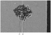
图5是采用螺栓作为目标物并拍摄到螺栓被散乱堆放的情形的第一图像的例子。Fig. 5 is an example of a first image in which bolts are used as targets and the bolts are scattered and piled up.
图6是表示目标物的散乱堆放状态从图4所示的目标物的散乱堆放状态发生了变化时的图。FIG. 6 is a diagram showing when the scattered state of the objects has changed from the scattered state of the objects shown in FIG. 4 .
图7是表示第二实施方式涉及的机器人系统的功能框图。FIG. 7 is a functional block diagram showing a robot system according to a second embodiment.
图8是表示第三实施方式涉及的机器人系统的功能框图。FIG. 8 is a functional block diagram showing a robot system according to a third embodiment.
附图标记说明Explanation of reference signs
1…机器人、3…相机、4…物体检测装置、4a…处理器、4b…存储部、4c…外部接口、4d…系统总线、5…机器人控制装置、6…无人搬运车、7…底座、10…机械臂、11…臂、12…臂、13…臂、14…臂、15…臂、16…臂、17…末端执行器、41…相机控制部、42…物体位置姿势计算部、43…识别评价部、44…保持位置姿势计算部、45…任务评价部、46…拍摄位置姿势确定部、47…显示部、48…无人搬运车控制部、91…目标物、91A…目标物、91B…目标物、92…桌台、100…机器人系统、100A…机器人系统、100B…机器人系统、110…基台、R1…相关曲线、R2…相关曲线、S10…工序、S11…工序、S111…工序、S112…工序、S12…工序、S13…工序、S13-2…工序、S14…工序、S141…工序、S141-2…工序、S142…工序、S142-2…工序、S15…工序、S15-2…工序、S16…工序、S16-2…工序、S17…工序、S171…工序、S171-2…工序、S172…工序、S172-2…工序、S18…工序、S18-2…工序、S19…工序。1...robot, 3...camera, 4...object detection device, 4a...processor, 4b...storage unit, 4c...external interface, 4d...system bus, 5...robot controller, 6...unmanned guided vehicle, 7...base , 10...Robot arm, 11...Arm, 12...Arm, 13...Arm, 14...Arm, 15...Arm, 16...Arm, 17...End effector, 41...Camera control unit, 42...Object position and posture calculation unit, 43...Recognition evaluation unit, 44...Holding position and posture calculation unit, 45...Task evaluation unit, 46...Shooting position and posture determination unit, 47...Display unit, 48...Unmanned guided vehicle control unit, 91...Target object, 91A...Target Object, 91B...object, 92...desk, 100...robot system, 100A...robot system, 100B...robot system, 110...abutment, R1...correlation curve, R2...correlation curve, S10...process, S11...process, S111...process, S112...process, S12...process, S13...process, S13-2...process, S14...process, S141...process, S141-2...process, S142...process, S142-2...process, S15...process, S15-2...process, S16...process, S16-2...process, S17...process, S171...process, S171-2...process, S172...process, S172-2...process, S18...process, S18-2...process, S19 ... process.
具体实施方式detailed description
以下,基于附图所示的实施方式详细地说明本发明的物体检测方法、物体检测装置以及机器人系统。Hereinafter, the object detection method, object detection device, and robot system of the present invention will be described in detail based on the embodiments shown in the drawings.
1.第一实施方式1. First Embodiment
1.1机器人系统1.1 Robot system
首先,说明第一实施方式涉及的机器人系统。First, the robot system according to the first embodiment will be described.
图1是表示第一实施方式涉及的机器人系统的功能框图。FIG. 1 is a functional block diagram showing a robot system according to the first embodiment.
需要指出,图1中图示出X轴、Y轴以及Z轴作为互相正交的三个轴。另外,为了方便说明,将Z轴的前端方向设为“上”,将Z轴的基端方向设为“下”。It should be pointed out that the X axis, the Y axis and the Z axis are illustrated in FIG. 1 as three mutually orthogonal axes. In addition, for convenience of description, the direction of the distal end of the Z-axis is referred to as "up", and the direction of the proximal end of the Z-axis is referred to as "down".
图1所示的机器人系统100例如用于电子零部件等目标物91(物体)的保持、搬运以及组装等作业。该机器人系统100具有:机器人1,具备机械臂10;相机3(拍摄部),设置于机械臂10,并具有拍摄功能;物体检测装置4,检测目标物91;以及机器人控制装置5,基于物体检测装置4的检测结果控制机器人1的驱动。以下,依次说明各部。The
1.1.1机器人1.1.1 Robots
图1所示的机器人1是所谓的6轴垂直多关节机器人,具有基台110和连接到基台110的机械臂10。The robot 1 shown in FIG. 1 is a so-called 6-axis vertical articulated robot, and has a
基台110是将机器人1安装于任意的设置部位的部分。在本实施方式中,基台110设置于例如地板等设置部位。需要指出,基台110的设置部位不限于地板等,例如也可以是墙壁、天花板、能够移动的台车上等。因而,图1的Z轴不限于铅直轴。The
图1所示的机械臂10具有臂11、臂12、臂13、臂14、臂15以及臂16,并且其基端连接到基台110。这些臂11~16从基端朝向前端被依次连结。各臂11~16能够相对于相邻的臂或者基台110转动。The
另外,虽然未分别图示,但机器人1具有:使臂11相对于基台110转动的驱动装置、使臂12相对于臂11转动的驱动装置、使臂13相对于臂12转动的驱动装置、使臂14相对于臂13转动的驱动装置、使臂15相对于臂14转动的驱动装置、以及使臂16相对于臂15转动的驱动装置。各驱动装置具备电机、控制电机的驱动的控制器以及检测电机的旋转量的编码器,并由机器人控制装置5相互独立地进行控制。In addition, although not shown separately, the robot 1 has: a driving device that rotates the
如图1所示,在机械臂10的前端装配有能够吸附目标物91的末端执行器17。末端执行器17例如具备把持手爪、吸附手爪、磁手爪等,保持放置于桌台92上的目标物91而进行各种作业。As shown in FIG. 1 , an
1.1.2拍摄部1.1.2 Shooting Department
图1所示的相机3装配于机械臂10的前端部。此外,图1所示的相机3随着机械臂10的驱动而变更拍摄位置姿势,能够拍摄放置于桌台92上的目标物91。需要指出,“拍摄位置姿势”例如是指关于相机3的六自由度的位置姿势。The
相机3以能够进行通信的方式与物体检测装置4连接。需要指出,相机3与物体检测装置4的连接除了有线的连接之外,也可以是无线的连接。The
相机3是针对目标物91或其周围能够获取彩色图像、黑白图像、红外线图像等二维图像的装置即2D相机、以及能够拍摄深度图像(表面点群数据)的装置即3D相机中的任一方或者双方。其中,作为能够获取深度图像的装置,例如可举出通过相移法、主动立体法等计量拍摄对象的三维形状的三维计量装置等。The
1.1.3物体检测装置1.1.3 Object detection device
物体检测装置4以能够进行通信的方式与相机3和机器人控制装置5连接。需要指出,物体检测装置4与机器人控制装置5的连接除了有线的连接之外,也可以是无线的连接。The
另外,图1所示的物体检测装置4具有:相机控制部41(拍摄控制部)、物体位置姿势计算部42、识别评价部43、保持位置姿势计算部44、任务评价部45、拍摄位置姿势确定部46以及显示部47。由于通过末端执行器17保持散乱堆放在例如桌台92上的目标物91,因此图1所示的物体检测装置4检测目标物91,并推断其物体位置姿势。然后,能够基于检测结果和推断结果,经由机器人控制装置5控制机器人1的动作,使末端执行器17保持目标物91。需要指出,“物体位置姿势”是指关于目标物91的六自由度的位置姿势,例如是沿着X轴的位置、沿着Y轴的位置、沿着Z轴的位置、关于方位角的姿势、关于仰角的姿势以及关于旋转角的姿势。In addition, the
以下,说明物体检测装置4的各部。Each part of the
图1所示的相机控制部41与相机3连接,通过相机3拍摄放置于桌台92上的目标物91,并获取第一图像和第二图像。然后,将获取的第一图像和第二图像分别输出到物体位置姿势计算部42。例如在相机3由2D相机和3D相机两者构成的情况下,第一图像和第二图像分别由二维图像和深度图像构成。The
另外,相机控制部41在基于从拍摄位置姿势确定部46输出的拍摄位置姿势的信息变更相机3的拍摄位置姿势的情况下,将机械臂10的控制信号输出到机器人控制装置5。然后,经由机器人控制装置5控制机械臂10,来变更相机3的拍摄位置姿势。In addition, the
图1所示的物体位置姿势计算部42基于从相机控制部41输出的第一图像或第二图像,识别目标物91的拍摄位置姿势。具体地说,从第一图像或第二图像检测目标物91,并进行推断检测出的目标物91的物体位置姿势的运算。然后,将物体位置姿势的计算结果输出到识别评价部43和保持位置姿势计算部44。The object position and
图1所示的识别评价部43基于从物体位置姿势计算部42输出的计算结果,对第一图像的物体位置姿势识别数进行计数。具体地说,将在物体位置姿势计算部42中能够根据第一图像算出目标物91的物体位置姿势的数量设为物体位置姿势识别数。然后,将该物体位置姿势识别数输出到拍摄位置姿势确定部46。The
图1所示的保持位置姿势计算部44基于从物体位置姿势计算部42输出的目标物91的物体位置姿势,算出保持目标物91的末端执行器17(保持部)的保持位置姿势。该保持位置姿势能够基于预先按照目标物91的各种类保存着的数据库来进行计算。即,在例如用吸附手爪吸附保持目标物91的情况下,只要将适合吸附的面(吸附面)的物体位置姿势预先记录在数据库中即可。由此,能够基于目标物91的物体位置姿势求出吸附面的物体位置姿势,因此能够基于此算出末端执行器17的保持位置姿势。另外,在例如用把持手爪把持目标物91的情况下,只要将适合把持的面的物体位置姿势预先记录在数据库中即可。由此,能够算出适合把持的末端执行器17的保持位置姿势。然后,将末端执行器17的保持位置姿势输出到机器人控制装置5。即,为了由末端执行器17以该保持位置姿势保持目标物91,将为此的控制信号向机器人控制装置5输出。需要指出,“保持位置姿势”是指例如关于末端执行器17的六自由度的位置姿势。The holding position and
图1所示的任务评价部45获取能否通过末端执行器17(保持部)保持目标物91的结果、也就是保持成功与否的信息。然后,将保持成功与否作为任务评价值输出到拍摄位置姿势确定部46。需要指出,保持成功与否能够基于例如拍摄末端执行器17的相机、装配于末端执行器17的力检测器等的检测结果而求出。确认保持成功与否的相机既可以与上述相机3相同,也可以不同。The
图1所示的拍摄位置姿势确定部46求出包含从识别评价部43输出的物体位置姿势识别数和从任务评价部45输出的任务评价值的评价指标。然后,基于该评价指标,更新根据拍摄位置姿势推断评价指标的推断模型,并基于更新后的推断模型确定相机3的拍摄位置姿势。另外,将所确定的拍摄位置姿势输出到相机控制部41。The shooting position and posture specifying
图1所示的显示部47以能够通信的方式与拍摄位置姿势确定部46连接。此外,图1所示的物体检测装置4具有显示部47,显示部47显示从识别评价部43输出的物体位置姿势识别数、从任务评价部45输出的任务评价值以及包含它们的上述评价指标中至少之一。The
通过具有这样的显示部47,由此例如能够以数值确认物体检测装置4中的推断模型的妥当性。由此,能够目视确认定量地评价物体检测装置4的健全性的指标。By having such a
需要指出,作为显示部47,例如可举出液晶显示装置等。另外,在显示部47上显示的不限于上述信息,也可以是其以外的信息。In addition, as the
以上,说明了第一实施方式涉及的物体检测装置4的构成,在后面详述物体检测装置4的动作、即物体检测方法。The configuration of the
图2是表示图1所示的物体检测装置4的硬件构成的一例的图。FIG. 2 is a diagram showing an example of a hardware configuration of the
图2所示的物体检测装置4包括处理器4a、存储部4b以及外部接口4c。此外,这些各要素以能够进行通信的方式经由系统总线4d而相互连接。The
处理器4a具备CPU(Central Processing Unit:中央处理单元)等。此外,读出并执行存储在存储部4b中的各种程序等。由此,实现物体检测装置4中的各种运算、各种处理等。The
存储部4b保存能够由处理器4a执行的各种程序等。作为存储部4b,例如可举出RAM(Random Access Memory:随机存取存储器)等易失性存储器、ROM(Read Only Memory:只读存储器)等非易失性存储器、装卸式的外部存储装置等。需要指出,在存储部4b中除了程序之外还存储从上述各部输出的数据、设定值等。The
外部接口4c例如可举出有线LAN(Local Area Network:局域网)、无线LAN等。As the
需要指出,物体检测装置4的各部的功能通过处理器4a执行程序而实现,但也可以是至少一部分在硬件上实现。It should be noted that the functions of each part of the
另外,物体检测装置4既可以配置于机器人1的壳体内,也可以配置于壳体外,还可以经由网络等远距离设置。In addition, the
1.1.4机器人控制装置1.1.4 Robot control device
机器人控制装置5具有控制机器人1的动作的功能,如图1所示,以能够进行通信的方式与机器人1和物体检测装置4连接。需要指出,机器人控制装置5与机器人1和物体检测装置4之间既可以分别通过有线进行连接,也可以分别通过无线进行连接。另外,在机器人控制装置5上也可以连接有监视器等显示装置、键盘、触摸面板等输入装置等。The
虽未图示,但机器人控制装置5包括处理器、存储部以及外部接口,这些各要素经由各种总线而以能够进行通信的方式相互连接。Although not shown, the
处理器具备CPU(Central Processing Unit)等处理器,执行存储在存储部中的各种程序等。由此,能够实现机器人1的驱动的控制、各种运算和判断等处理。The processor includes processors such as a CPU (Central Processing Unit), and executes various programs and the like stored in the storage unit. Thereby, processing such as control of the drive of the robot 1 , various calculations, and judgments can be realized.
1.2物体检测方法1.2 Object detection method
接着,说明第一实施方式涉及的物体检测方法。Next, the object detection method according to the first embodiment will be described.
图3是表示第一实施方式涉及的物体检测方法的流程图。FIG. 3 is a flowchart showing an object detection method according to the first embodiment.
图3所示的物体检测方法是检测目标物91的物体位置姿势的方法。本实施方式涉及的物体检测方法例如即使散乱堆放的目标物91的状态在短时间内变化,也能够稳定地检测目标物91。然后,能够基于目标物91的检测结果,经由机器人控制装置5控制机器人1的动作,使末端执行器17稳定地保持目标物91。The object detection method shown in FIG. 3 is a method of detecting the object position and posture of the
图3所示的物体检测方法是检测目标物91的物体位置姿势的方法,具有:工序S10,确定相机3的拍摄位置姿势;工序S111,将相机3配置成拍摄位置姿势;工序S112,通过相机3拍摄多个目标物91而获取第一图像;工序S12,识别目标物91的物体位置姿势;工序S13,对物体位置姿势识别数进行计数来评价识别结果;工序S141,算出末端执行器17的保持位置姿势;工序S142,输出通过末端执行器17保持目标物91的控制信号;工序S15,将能否保持目标物91的结果作为任务评价值进行计算,并评价保持结果;工序S16,基于包含物体位置姿势识别数和任务评价值的评价指标,更新推断模型,并基于更新后的推断模型,确定相机3的更新拍摄位置姿势;工序S171,将相机3配置成更新拍摄位置姿势;工序S172,通过相机3拍摄目标物91而获取第二图像;工序S18,识别目标物91的物体位置姿势;以及工序S19,判断是否结束目标物91的拍摄。The object detection method shown in Fig. 3 is a method for detecting the object position and posture of the target object 91, which has: operation S10, determining the shooting position and posture of the camera 3; operation S111, configuring the camera 3 to the shooting position and posture; 3 Shooting a plurality of targets 91 to obtain the first image; step S12, identifying the object position and posture of the target object 91; step S13, counting the number of recognized object positions and postures to evaluate the recognition result; step S141, calculating the position and posture of the end effector 17 Maintain the position and posture; process S142, output the control signal for holding the target object 91 through the end effector 17; process S15, calculate the result of whether the target object 91 can be held as a task evaluation value, and evaluate the holding result; process S16, based on the The object position and posture recognition number and the evaluation index of the task evaluation value, update the inference model, and based on the updated inference model, determine the updated shooting position and posture of the camera 3; process S171, configure the camera 3 to update the shooting position and posture; process S172, The camera 3 captures the target object 91 to obtain a second image; step S18 , identifying the object position and posture of the target object 91 ; and step S19 , judging whether to end the shooting of the target object 91 .
根据这种物体检测方法,立足于拍摄目标物91的相机3的拍摄位置姿势对目标物91的识别成功与否、任务的成功与否造成影响,以提高识别数、任务成功数的方式确定更新拍摄位置姿势。而且,在工作期间能够逐次变更更新拍摄位置姿势,因此即使在目标物91的周边环境在短时间内发生变化的情况下,也能够进行目标物91的恰当的保持。因此,例如在照明等条件易于变化的环境下保持目标物91的作业、保持堆积如山的目标物91的作业等中,也能够识别目标物91而不用费事进行识别目标物91的调试。According to this object detection method, based on the shooting position and posture of the
以下,依次说明各工序。Hereinafter, each step will be described in order.
1.2.1确定拍摄位置姿势(工序S10)1.2.1 Determining the shooting position and posture (process S10)
首先,通过拍摄位置姿势确定部46确定相机3的拍摄位置姿势。在本工序中,由于是初始状态,因此不存在用于确定拍摄位置姿势的图像。为此,在该阶段,也可以任意地确定拍摄位置姿势,但在本实施方式中,基于拍摄位置姿势确定部46拥有的推断模型进行确定。该推断模型将在后面描述,其是根据相机3的拍摄位置姿势推断前述的评价指标的模型。在作为最先的工序的本工序S10中,推断模型没有立足于过去的经验的内容,因此基于任意给定的推断模型确定拍摄位置姿势即可。First, the shooting position and posture of the
图4是表示散乱堆放的目标物91与用于确定拍摄位置姿势的评价指标的一例的关系的图表。需要指出,相机3的拍摄位置姿势具有6个自由度,但在图4中,仅图示出其中的沿着X轴的平移的自由度即位置x。另外,在以下的说明中,仅说明沿着X轴的平移。因而,虽然在本实施方式中未进行说明,但关于余下的5个自由度、也就是沿着Y轴的平移、沿着Z轴的平移、绕X轴的姿势、绕Y轴的姿势以及绕Z轴的姿势,物体检测方法也能够确定与识别数、任务成功数相应的恰当的拍摄位置姿势。FIG. 4 is a graph showing an example of the relationship between
在图4中示出了位置a作为本工序中所确定的拍摄位置姿势的一例。The position a is shown in FIG. 4 as an example of the imaging position and posture specified in this step.
1.2.2相机的配置(工序S111)1.2.2 Arrangement of cameras (process S111)
接着,使相机3移动,以处于所确定的拍摄位置姿势。即,使相机3移动,以使相机3的沿着X轴的位置x处于位置a。在本实施方式中,相机3装配于机械臂10的前端部。相机控制部41基于从拍摄位置姿势确定部46输出的拍摄位置姿势,向机器人控制装置5输出控制信号。由此,控制机械臂10,使相机3移动,以成为目标拍摄位置姿势。Next, the
1.2.3目标物的拍摄(工序S112)1.2.3 Shooting of the target (process S112)
接着,由相机3在该拍摄位置姿势下以多个目标物91进入同一视野内的方式拍摄第一图像。拍摄到的第一图像由相机控制部41获取。然后,将第一图像输出到物体位置姿势计算部42。Next, the
1.2.4目标物的位置姿势的识别(工序S12)1.2.4 Recognition of the position and posture of the target (step S12)
接着,由物体位置姿势计算部42基于第一图像识别目标物91的物体位置姿势。识别目标物91的物体位置姿势是指,进行在第一图像中检测目标物91以及推断目标物91的物体位置姿势这两者。Next, the object position and orientation of the
作为在第一图像中检测目标物91的具体的一个方法,例如可举出基于第一图像中包含的二维图像的对比度而指定目标物91的轮廓的方法。As a specific method of detecting the
作为识别目标物91的物体位置姿势的具体的一个方法,例如可举出使第一图像与目标物91的设计数据匹配的方法。目标物91的设计数据例如是指能够以三维制图软件进行处理的三维CAD(Computer-Aided Design,计算机辅助设计)数据、由点、线、面等模型的结构要素构成且能够以三维计算机图形软件进行处理的三维CG(Computer Graphics,计算机图形)数据等。As a specific method of recognizing the object position and posture of the
另外,作为识别目标物91的物体位置姿势的具体的另一个方法,例如也可举出通过机器学习而根据第一图像推断目标物91的物体位置姿势的方法等,其中,该机器学习用到通过第一图像与物体位置姿势标签的配对所表现的学习数据。物体位置姿势标签是表示图像中目标物91的位置的坐标数据。In addition, as another specific method of recognizing the object position and posture of the
图5是将螺栓用作目标物91并拍摄到螺栓被散乱堆放的情形的第一图像的例子。此外,对在物体位置姿势计算部42中能够识别到的目标物91标注了包围其轮廓的线。FIG. 5 is an example of a first image in which bolts are used as the
需要指出,第一图像例如设为二维图像或深度图像,优选包含二维图像和深度图像两者。通过获取这些第一图像,由此能够基于第一图像识别目标物91的位置姿势。It should be pointed out that, for example, the first image is set as a two-dimensional image or a depth image, and preferably includes both the two-dimensional image and the depth image. By acquiring these first images, the position and posture of the
当像这样地进行了目标物91的物体位置姿势识别时,将其识别结果、即能够识别到物体位置姿势的数量输出到识别评价部43。When the object position and posture recognition of the
1.2.5识别结果的评价(工序S13)1.2.5 Evaluation of recognition results (step S13)
接着,识别评价部43将在第一图像中能够识别到目标物91的物体位置姿势的数量作为物体位置姿势识别数进行处理。于是,在物体位置姿势识别数多的情况下,能够将拍摄到该第一图像的拍摄位置姿势评价为是识别成功数多的拍摄位置姿势。然后,将物体位置姿势识别数输出到拍摄位置姿势确定部46。Next, the
另外,在识别评价部43中,当在第一图像中识别到多个目标物91的情况下,从识别到的多个目标物91中确定应由末端执行器17保持的1个目标物91。确定时的基准没有特别限定,例如除了如图5所示地将推断结果投影到二维图像上时的轮廓的一致度以外,还可举出将推断结果投影到深度图像上时的深度的一致度、相机3与目标物91的接近度等。然后,将所确定的应由末端执行器17保持的1个目标物91的物体位置姿势信息输出到保持位置姿势计算部44。In addition, in the
1.2.6末端执行器的保持位置姿势的计算(工序S141)1.2.6 Calculation of the holding position and posture of the end effector (process S141)
接着,由保持位置姿势计算部44基于应由末端执行器17保持的1个目标物91的物体位置姿势信息计算保持该目标物91的末端执行器17的保持位置姿势。需要指出,为了计算保持位置姿势,如上所述,使用按目标物91的各个种类预先保存的数据库,基于该数据库算出最适合保持目标物91的末端执行器17的保持位置姿势。Next, the holding position and
1.2.7目标物的保持(工序S142)1.2.7 Hold of target object (step S142)
然后,输出由末端执行器17以上述的保持位置姿势保持目标物91的控制信号。控制信号输出到机器人控制装置5。在机器人控制装置5中,基于该控制信号控制机器人1的驱动,使末端执行器17的保持位置姿势进行变更。然后,由末端执行器17尝试保持目标物91。Then, a control signal for holding the
1.2.8保持结果的评价(工序S15)1.2.8 Evaluation of retention results (process S15)
接着,由任务评价部45经由机器人控制装置5获取能否由末端执行器17保持目标物91的结果、也就是保持成功与否的信息。在任务评价部45中,将保持成功与否作为任务评价值进行计算,并将其输出到拍摄位置姿势确定部46。Next, the result of whether the
1.2.9更新拍摄位置姿势的确定(工序S16)1.2.9 Determination of Update Shooting Position and Posture (Process S16)
接着,在拍摄位置姿势确定部46中,算出包含从识别评价部43输出的物体位置姿势识别数和从任务评价部45输出的任务评价值的评价指标。然后,使算出的评价指标反映到在拍摄位置姿势确定部46中拥有的推断模型。该推断模型例如是采用贝叶斯(Bayesian)推断的模型。在贝叶斯推断中,具有立足于过去的经验的模型,使最近的评价指标反映到该模型,从而更新模型。由此,能够立足于过去的经验和最近的评价结果而确定最佳的更新拍摄位置姿势。Next, in the imaging position and posture specifying
作为在拍摄位置姿势确定部46中算出的评价指标的例子,可举出如下式那样的、物体位置姿势识别数与任务评价值的线性组合。As an example of the evaluation index calculated by the photographing position and posture specifying
f(x)=D(x)+S(x)f(x)=D(x)+S(x)
需要指出,f(x)是表示评价指标的评价函数,D(x)是物体位置姿势识别数,S(x)是任务评价值。需要指出,任务评价值在通过上述的末端执行器17成功保持的情况下,设定成比失败时更大的数值。例如,在一幅第一图像中的物体位置姿势识别数为10的情况下,将针对从该第一图像检测出的1个目标物91尝试的保持成功时的任务评价值设为5,保持失败时的任务评价值设为0即可。这样一来,保持成功时的评价函数f(x)为10+5=15,保持失败时的评价函数f(x)为10+0=10。这样,通过采用不仅包含物体位置姿势识别数而且还包含任务评价值的评价指标并对其进行反映,从而来更新推断模型。由此,推断模型能够识别大多数目标物91,并且被逐次更新,以探索易于成功保持目标物91的位置x。It should be pointed out that f(x) is the evaluation function representing the evaluation index, D(x) is the number of object position and posture recognition, and S(x) is the task evaluation value. It should be noted that the task evaluation value is set to a larger value when the mission evaluation value is successfully held by the above-mentioned
另外,通过逐次更新推断模型,由此能够使推断模型追随围绕目标物91的环境的变化。由此,通过基于该推断模型确定更新拍摄位置姿势,从而能求出可提高末端执行器17的保持成功率的更新拍摄位置姿势。In addition, by sequentially updating the estimation model, the estimation model can be made to follow changes in the environment surrounding the
需要指出,任务评价值的值不限于上述值,也可以是任意的值。It should be noted that the value of the task evaluation value is not limited to the above-mentioned values, and may be any value.
另外,在贝叶斯推断中,获取关于各种位置x的评价函数f(x),并将其反映到推断模型,由此逐渐探索可提高评价函数f(x)的值的位置x。若反复进行该探索,则可得到表示位置x与评价函数f(x)的关系的如图4所示的相关曲线R1。在图4中,由于纵轴取评价函数f(x),因此越是纵轴的前端,表示评价函数f(x)的值越大。在本工序中,为了便于说明,假设在该时间点,通过若干次位置x的探索,已求出某种程度的该相关曲线R1。Also, in Bayesian inference, evaluation functions f(x) for various positions x are acquired and reflected in an inference model, thereby gradually searching for positions x that can increase the value of the evaluation function f(x). When this search is repeated, a correlation curve R1 as shown in FIG. 4 showing the relationship between the position x and the evaluation function f(x) can be obtained. In FIG. 4 , since the evaluation function f(x) is taken on the vertical axis, the higher the front end of the vertical axis, the larger the value of the evaluation function f(x). In this step, for convenience of description, it is assumed that the correlation curve R1 has been obtained to some extent by searching for the position x several times at this point in time.
这样一来,在图4所示的相关曲线R1中,通过将拍摄位置姿势的位置x从位置a变更为位置b,从而能够推断出可相对地增大评价函数f(x)的值。因而,在本工序中,将该位置b确定为新的拍摄位置姿势(更新拍摄位置姿势),并将其确定结果输出到相机控制部41。该新的拍摄位置姿势是在概率上末端执行器17的保持成功率高的拍摄位置姿势。In this way, in the correlation curve R1 shown in FIG. 4 , by changing the position x of the imaging position and posture from position a to position b, it can be inferred that the value of the evaluation function f(x) can be relatively increased. Therefore, in this step, the position b is determined as a new imaging position and orientation (updated imaging position and orientation), and the determination result is output to the
1.2.10相机的配置(工序S171)1.2.10 Arrangement of camera (process S171)
接着,控制机器人1的机械臂10的驱动来配置相机3,使其处于所确定的更新拍摄位置姿势。Next, the driving of the
1.2.11目标物的拍摄(工序S172)1.2.11 Shooting of target object (process S172)
接着,由相机3以多个目标物91进入同一视野内的方式拍摄第二图像。拍摄到的第二图像由相机控制部41获取。然后,将第二图像输出到物体位置姿势计算部42。Next, the
1.2.12目标物的物体位置姿势的识别(工序S18)1.2.12 Recognition of the object position and posture of the target (process S18)
接着,由物体位置姿势计算部42基于第二图像识别目标物91的物体位置姿势。基于第二图像的目标物91的识别方法与上述基于第一图像的目标物91的识别方法相同。Next, the object position and orientation of the
当像这样地进行了目标物91的物体位置姿势识别时,将其识别结果、即能够识别到物体位置姿势的数量输出到识别评价部43。When the object position and posture recognition of the
1.2.13是否结束目标物的拍摄的判断(工序S19)1.2.13 Judgment of whether to end the shooting of the target (step S19)
接着,判断是否结束目标物91的拍摄。即,若完成了放置于桌台92上的全部目标物91的保持,则结束拍摄即可。另一方面,在仍然残留有要保持的目标物91的情况下,返回到上述的工序S13之前。Next, it is judged whether or not to end the imaging of the
然后,再次按照目标物91的数量反复进行与工序S13、工序S141、工序S142、工序S15、工序S16、工序S171、工序S172以及工序S18同样的各工序。由此,能够逐个保持目标物91,并且更新推断模型。Then, the same steps as step S13 , step S141 , step S142 , step S15 , step S16 , step S171 , step S172 , and step S18 are repeated again according to the number of
在此,将这些工序的第二次作为工序S13-2、工序S14-2(工序S141-2、工序S142-2)、工序S15-2、工序S16-2、工序S17-2(工序S171-2、工序S172-2)以及工序S18-2来进行说明。Here, the second of these steps is referred to as step S13-2, step S14-2 (step S141-2, step S142-2), step S15-2, step S16-2, step S17-2 (step S171-2). 2. Step S172-2) and step S18-2 will be described.
1.2.14识别结果的评价(工序S13-2)1.2.14 Evaluation of recognition results (process S13-2)
接着,由识别评价部43将能够在第二图像中识别到目标物91的物体位置姿势的数量作为物体位置姿势识别数进行计数。Next, the number of object positions and postures in which the
另外,从在第二图像中识别出的目标物91中确定应由末端执行器17保持的1个目标物91。In addition, one
1.2.15末端执行器的保持位置姿势的计算(工序S141-2)1.2.15 Calculation of the holding position and posture of the end effector (process S141-2)
接着,由保持位置姿势计算部44基于应由末端执行器17保持的1个目标物91的物体位置姿势信息计算保持该目标物91的末端执行器17的保持位置姿势。需要指出,为了计算保持位置姿势,如上所述,使用按目标物91的各个种类预先保存的数据库,基于该数据库算出最适合保持目标物91的末端执行器17的保持位置姿势。Next, the holding position and
1.2.16目标物的保持(工序S142-2)1.2.16 Hold of target object (process S142-2)
然后,输出由末端执行器17以上述的保持位置姿势保持目标物91的控制信号。控制信号输出到机器人控制装置5。在机器人控制装置5中,基于该控制信号控制机器人1的机械臂10的驱动,使末端执行器17的保持位置姿势进行变更。然后,由末端执行器17尝试保持目标物91。Then, a control signal for holding the
1.2.17保持结果的评价(工序S15-2)1.2.17 Evaluation of retention results (process S15-2)
接着,由任务评价部45经由机器人控制装置5获取能否由末端执行器17保持目标物91的结果、也就是保持成功与否的信息。在任务评价部45中,将保持成功与否作为任务评价值对其进行计算,并将其输出到拍摄位置姿势确定部46。Next, the result of whether the
1.2.18更新拍摄位置姿势的确定(工序S16-2)1.2.18 Determination of updated shooting position and posture (process S16-2)
接着,在拍摄位置姿势确定部46中,算出包含从识别评价部43输出的物体位置姿势识别数和从任务评价部45输出的任务评价值的评价指标。然后,使算出的评价指标反映到在拍摄位置姿势确定部46中拥有的推断模型,进一步更新推断模型。由此,能够基于更新后的推断模型确定最佳的更新拍摄位置姿势。Next, in the imaging position and posture specifying
1.2.19相机的配置(工序S171-2)1.2.19 Arrangement of camera (process S171-2)
接着,控制机器人1的机械臂10的驱动来配置相机3,使其处于所确定的更新拍摄位置姿势。Next, the driving of the
1.2.20目标物的拍摄(工序S172-2)1.2.20 Shooting of the target (process S172-2)
接着,由相机3在所配置的更新拍摄位置姿势下以多个目标物91进入同一视野内的方式拍摄第三图像。拍摄到的第三图像由相机控制部41获取。然后,将第三图像输出到物体位置姿势计算部42。Next, a third image is captured by the
1.2.21目标物的保持位置姿势的识别(工序S18-2)1.2.21 Recognition of the holding position and posture of the target (process S18-2)
接着,由物体位置姿势计算部42基于第三图像识别目标物91的保持位置姿势。基于第三图像的目标物91的识别方法与上述的基于第一图像的目标物91的识别方法相同。Next, the holding position and posture of the
进一步将与如上所述的作为第二次的各工序的工序S13-2、工序S141-2、工序S142-2、工序S15-2、工序S16-2、工序S171-2、工序S172-2以及工序S18-2同样的工序反复进行第三次、第4次……,由此能够不断更新用于探索评价函数f(x)的值高的位置x的推断模型。其结果,能够不断探索进一步提高目标物91的保持成功率的位置x。Furthermore, the steps S13-2, S141-2, S142-2, S15-2, S16-2, S171-2, S172-2 and By repeating the same steps as step S18-2 for the third time, the fourth time..., the estimation model for searching for the position x where the value of the evaluation function f(x) is high can be constantly updated. As a result, it is possible to continuously search for a position x that further increases the success rate of holding the
当像这样地更新了推断模型时,如图4所示,拍摄位置姿势的位置x按照位置a→位置b→位置c→位置d进行移动,每次可得到更大的评价函数f(x)的值。在本实施方式涉及的物体检测方法中,由于能够不断探索可提高物体位置姿势识别数、任务评价值的拍摄位置姿势,因此能够高效地识别、检测例如可期待高的保持成功率的目标物91。由此,能够高效地进行保持目标物91的作业。When the inference model is updated in this way, as shown in Fig. 4, the position x of the photographing position and posture moves from position a → position b → position c → position d, and a larger evaluation function f(x) can be obtained each time value. In the object detection method according to this embodiment, since it is possible to continuously search for shooting positions and postures that can increase the number of object position and posture recognitions and task evaluation values, it is possible to efficiently recognize and detect, for example, the
需要指出,当更新了推断模型时,每次相关曲线R1变化,但在图4中,为了便于说明,图示成相关曲线R1没有发生变化。另外,每当更新推断模型时,评价函数f(x)的值未必总是高,也可以是低的。It should be noted that when the estimation model is updated, the correlation curve R1 changes each time, but in FIG. 4 , the correlation curve R1 is shown not to change for convenience of explanation. In addition, the value of the evaluation function f(x) does not always have to be high every time the inference model is updated, and may be low.
综上所述,本实施方式涉及的物体检测方法是检测目标物91的物体位置姿势的方法,其具有:工序S11(工序S111、S112),通过相机3(拍摄部)拍摄多个目标物91而获取第一图像;工序S12,基于第一图像识别目标物91的物体位置姿势;工序S13,将能够识别到目标物91的物体位置姿势的数量作为物体位置姿势识别数进行计数;工序S14(工序S141、S142),基于目标物91的物体位置姿势,输出由末端执行器17(保持部)保持目标物91的控制信号;工序S15,将能否保持目标物91的结果作为任务评价值进行计算;工序S16,基于包含物体位置姿势识别数和任务评价值的评价指标,更新根据相机3的拍摄位置姿势推断评价指标的推断模型,并基于更新后的推断模型确定相机3的更新拍摄位置姿势;工序S17(工序S171、S172),以更新拍摄位置姿势拍摄多个目标物91而获取第二图像;以及工序S18,基于第二图像识别目标物91的物体位置姿势。To sum up, the object detection method according to this embodiment is a method for detecting the object position and posture of the
根据这种物体检测方法,即使在目标物91的周边环境在短时间内发生变化的情况下,也能够追随该变化恰当地识别目标物91。因此,由于基于该识别结果,所以能够在机器人1中以高成功率保持目标物91。由此,例如在照明等条件易于变化的环境下保持目标物91的作业、保持堆积如山的目标物91的作业等中,也能够识别目标物91而不用费事进行识别目标物91的调试。其结果,能够针对目标物91高效地进行各种作业。According to such an object detection method, even if the surrounding environment of the
另外,在图6中图示出目标物91的散乱堆放状态从图4所示的目标物91的散乱堆放状态发生了变化的情况。具体地说,图4中,在桌台92上,稍靠左侧堆积的目标物91在图6中移至稍靠右侧。在这种情况下,反映了图4所示的散乱堆放状态的相关曲线R1并未反映图6的散乱堆放状态。因此,当欲保持处于图6所示的散乱堆放状态的目标物91时,为了求出用于识别可期待高的保持成功率的目标物91的拍摄位置姿势,需要使该散乱堆放状态的变化反映到根据拍摄位置姿势推断评价指标的推断模型。In addition, FIG. 6 illustrates a case where the scattered state of the
因此,在本实施方式中,作为用于确定拍摄位置姿势的推断模型,优选使用引入了遗忘率的概念的贝叶斯推断的模型。如上所述,贝叶斯推断是依据过去的经验和最近的评价结果来求出最佳的更新拍摄位置姿势的算法,通过将遗忘率的概念引入其中,从而能够引入越是在时间上接近的数据越能够信赖这一前提。由此,一边逐渐遗忘过去的经验,一边更新推断模型。其结果,例如对于以图6所示的位置a的拍摄位置姿势得到的评价指标,能够弱化向推断模型的反映程度。这样一来,即使发生了从图4所示的目标物91的散乱堆放状态到图6所示的散乱堆放状态的变化,通过反复进行推断模型的更新,从而也能够自推断模型逐渐排除图4所示的散乱堆放状态的数据。其结果,能够逐渐构建最适合变化后的散乱堆放状态的推断模型。Therefore, in the present embodiment, it is preferable to use a Bayesian inference model that incorporates the concept of a forgetting rate as an inference model for specifying the shooting position and posture. As mentioned above, Bayesian inference is an algorithm that finds the optimal update shooting position and posture based on past experience and recent evaluation results. By introducing the concept of forgetting rate into it, it is possible to introduce The more data can be trusted with this premise. As a result, the inference model is updated while gradually forgetting the past experience. As a result, for example, the degree of reflection in the estimation model can be weakened for the evaluation index obtained from the imaging position and posture of the position a shown in FIG. 6 . In this way, even if there is a change from the scattered state of
当像这样地构建了最适合图6所示的散乱堆放状态的推断模型时,关于表示位置x与评价函数f(x)的关系的相关曲线,也能够求出作为新的相关曲线R2。基于该相关曲线R2,将位置x设为例如图6的位置e,从而能够推断出可得到相对大的评价函数f(x)的值。由此,在散乱堆放状态发生了变化的情况下,也能够求出可期待高的保持成功率的新的更新拍摄位置姿势。When the estimation model optimal for the scattered stacking state shown in FIG. 6 is constructed in this way, a new correlation curve R2 can also be obtained for the correlation curve showing the relationship between the position x and the evaluation function f(x). Based on this correlation curve R2, it can be estimated that a relatively large value of the evaluation function f(x) can be obtained by setting the position x to, for example, the position e in FIG. 6 . Thereby, even when the scattered stacking state has changed, it is possible to obtain a new updated imaging position and posture that can be expected to maintain a high success rate.
需要指出,作为引入了遗忘率的概念的贝叶斯推断,例如能够采用人工智能学会论文志、23卷1号E(2008年)第50页~第57页的“对于非稳态数据的Sparse BayesianLearning”中记载的非稳态SBL(Sparse Bayesian Learning:稀疏贝叶斯学习)。It should be pointed out that as the Bayesian inference that introduces the concept of forgetting rate, for example, "Sparse data for non-stationary data" can be used, for example, in Journal of the Society for Artificial Intelligence, Vol. 23, No. 1 E (2008), pages 50 to 57. Unsteady SBL (Sparse Bayesian Learning: Sparse Bayesian Learning) recorded in Bayesian Learning".
另外,任务评价值也可以包含能否通过末端执行器17(保持部)保持目标物91的结果以外的要素。具体地说,任务评价值也可以包含在通过末端执行器17保持目标物91之后进行用到目标物91的作业后的结果。作为这种作业,例如在目标物91是螺栓的情况下,可举出在通过末端执行器17保持该螺栓之后将螺栓插入至形成有内螺纹的构件的作业等。于是,将这种作业成功与否与上述的保持成功与否同样地并入评价指标。由此,使用评价指标更新的推断模型使用不仅包含保持成功与否而且还包含用到所保持的目标物91的作业成功与否的任务评价值来进行更新。这样一来,能够求出不仅关于保持成功与否而且关于作业的成功与否也可期待高的成功率的新的更新拍摄位置姿势。In addition, the mission evaluation value may include elements other than the result of whether or not the
需要指出,在评价指标中并入作业成功与否的情况下,也可以进行加权,从而使保持成功与否的评价与作业成功与否的评价的权重不同。It should be pointed out that in the case of incorporating the success or failure of the job into the evaluation index, weighting may also be performed, so that the weights of the evaluation of whether the job is successful or not and the evaluation of whether the job is successful or not are different.
另外,本实施方式涉及的物体检测装置4是检测目标物91的物体位置姿势的装置,其具有:相机控制部41(拍摄控制部),通过相机3(拍摄部)拍摄获取包含多个目标物91的第一图像;物体位置姿势计算部42,基于第一图像,识别目标物91的物体位置姿势;识别评价部43,将能够识别到目标物91的物体位置姿势的数量作为物体位置姿势识别数进行计数;保持位置姿势计算部44,基于目标物91的物体位置姿势,计算保持目标物91的末端执行器17(保持部)的保持位置姿势,并输出由末端执行器17以该保持位置姿势保持目标物91的控制信号;任务评价部45,获取能否由末端执行器17保持目标物91的结果,并计算任务评价值;以及拍摄位置姿势确定部46,基于包含物体位置姿势识别数和任务评价值的评价指标,更新根据相机3的拍摄位置姿势推断评价指标的推断模型,并基于更新后的推断模型,确定相机3的更新拍摄位置姿势。此外,相机控制部41使相机3在更新拍摄位置姿势下拍摄获取第二图像,物体位置姿势计算部42基于第二图像,识别目标物91的物体位置姿势。In addition, the
根据这种物体检测装置4,逐次更新根据拍摄位置姿势推断评价指标的推断模型,因此能够以可识别例如能够期待高的保持成功率的目标物91的方式求出更新拍摄位置姿势。因而,通过具备该物体检测装置4,从而能够实现保持成功率高的机器人系统100。According to such an
另外,在目标物91的周边环境在短时间内变化的情况下,也能够通过推断模型的逐次更新而恰当地识别目标物91。由此,例如在照明等条件易于变化的环境下保持目标物91的作业、保持容易崩塌的堆积如山的目标物91的作业等中,也能够进行可期待高的保持成功率的目标物91的识别而不用费事进行识别目标物91的调试。其结果,即便在这种环境下也能够高效地保持目标物91。In addition, even when the surrounding environment of the
另外,本实施方式涉及的机器人系统100具有:机器人1,其具备机械臂10;相机3(拍摄部),其设置于机械臂10;上述的物体检测装置4;以及机器人控制装置5,其基于物体检测装置4的检测结果来控制机器人1的驱动。In addition, the
根据这种机器人系统100,在物体检测装置4中,即使在目标物91的周边环境在短时间内变化的情况下,也能够追随该变化而恰当地识别目标物91。因此,能够容易地实现可高效地保持目标物91的机器人系统100。According to such a
2.第二实施方式2. Second Embodiment
接着,说明第二实施方式涉及的机器人系统。Next, a robot system according to the second embodiment will be described.
图7是表示第二实施方式涉及的机器人系统的功能框图。FIG. 7 is a functional block diagram showing a robot system according to a second embodiment.
以下,说明第二实施方式涉及的机器人系统,但在以下的说明中,围绕与第一实施方式涉及的机器人系统的不同之处进行说明,关于同样的事项则省略其说明。需要指出,在图7中,对于与第一实施方式同样的构成标注同一附图标记。Hereinafter, the robot system according to the second embodiment will be described, but in the following description, the differences from the robot system according to the first embodiment will be described, and the description of the same matters will be omitted. In addition, in FIG. 7, the same code|symbol is attached|subjected to the structure similar to 1st Embodiment.
本实施方式涉及的机器人系统100A除了具有搭载机器人1的无人搬运车6之外,与第一实施方式涉及的机器人系统100相同。A
该无人搬运车6也被称为AGV(Automated Guided Vehicle:自动导引车),通过以各种引导方式进行引导而在规定的路径上自动地移动。此外,在本实施方式涉及的机器人系统100A中,在该无人搬运车6上搭载有机器人1。This unmanned guided
根据这种机器人系统100A,针对放置于相互分开的场所的目标物91A、91B,在物体检测装置4中均能够恰当地进行识别。也就是说,在场所不同的情况下,照明条件等会发生变化,相机3对目标物91A、91B的观感也是不同的。然而,在物体检测装置4中,逐次更新推断模型,由此能够使观感的变化难以对保持成功率造成影响。也就是说,即便在目标物91A、91B被放置于相互分开的场所的情况下,也能够与各自的场所相应地更新推断模型。其结果,能够一面构建用到无人搬运车6的机动性高的机器人系统100A,一面抑制目标物91A、91B的保持成功率降低。According to such a
需要指出,在如上述那样构成为机器人1的位置变化的情况下,也可以使得即便机器人1的位置改变也持续更新同一推断模型。然而,相互分开的目标物91A、91B的周边环境多数差别较大,因此在保持这些目标物91A、91B的机器人1中,相机3拍摄的图像的观感也较大地变化。在这种情况下,若确定目标物91A的拍摄位置姿势时使用的推断模型与确定目标物91B的拍摄位置姿势时使用的推断模型相同,则有可能因更新而产生推断模型发散等不良情况,推断模型的更新反而有可能使保持成功率降低。It should be noted that, in the case where the position of the robot 1 changes as described above, the same estimation model may be continuously updated even if the position of the robot 1 changes. However, since the surrounding environments of the
因此,拍摄位置姿势确定部46优选在机器人1的位置发生了变化时,将推断模型初始化。换言之,优选预先准备相互独立的多个推断模型,每当机器人1的位置变化时则切换推断模型。由此,各推断模型根据各自的环境而更新为最佳,因此即使在如本实施方式涉及的机器人系统100A这样用于边移动边保持(拣选)目标物91A、91B的用途的情况下,也能够抑制目标物91A、91B的保持成功率降低。Therefore, it is preferable that the imaging position and posture specifying
需要指出,图7所示的机器人系统100A具有与无人搬运车6连接的无人搬运车控制部48。无人搬运车控制部48基于来自机器人控制装置5的控制信号控制无人搬运车6的驱动。另外,将与无人搬运车6的位置相应的信号输出到物体检测装置4。在物体检测装置4中,也可以基于该信号来切换推断模型。It should be noted that the
在如上所述的第二实施方式中,也能够得到与第一实施方式同样的效果。Also in the second embodiment as described above, the same effect as that of the first embodiment can be obtained.
需要指出,不限于无人搬运车6搭载机器人1,也可以是各种台车等。另外,不限于将目标物91A、91B放置于桌台,也可以放置于架子等。It should be pointed out that the robot 1 mounted on the unmanned guided
3.第三实施方式3. Third Embodiment
接着,说明第三实施方式涉及的机器人系统。Next, a robot system according to a third embodiment will be described.
图8是表示第三实施方式涉及的机器人系统的功能框图。FIG. 8 is a functional block diagram showing a robot system according to a third embodiment.
以下,说明第三实施方式涉及的机器人系统,但在以下的说明中,围绕与第一实施方式涉及的机器人系统的不同之处进行说明,关于同样的事项则省略其说明。需要指出,在图8中,对于与第一实施方式同样的构成标注同一附图标记。Hereinafter, the robot system according to the third embodiment will be described, but in the following description, the differences from the robot system according to the first embodiment will be described, and the description of the same items will be omitted. In addition, in FIG. 8, the same code|symbol is attached|subjected to the structure similar to 1st Embodiment.
本实施方式涉及的机器人系统100B除了相机3(拍摄部)不是搭载于机械臂10的前端部而是搭载于与机械臂10分开的底座7上之外,均与第一实施方式涉及的机器人系统100相同。The
即,底座7设置于在设置有机器人1的地板上铺设的导轨等上。此外,相机3固定于底座7,能够拍摄置于桌台92上的目标物91。另外,虽然在图8中未图示,但底座7基于来自前述的相机控制部41的控制信号在导轨上移动。由此,能够将相机3配置成目标拍摄位置姿势。That is, the base 7 is installed on a guide rail or the like laid on the floor on which the robot 1 is installed. In addition, the
在采用了这种固定的相机3的机器人系统100B中,也能够得到与上述的机器人系统100同样的效果。Also in the
以上,基于图示的实施方式说明了本发明的物体检测方法、物体检测装置以及机器人系统,但本发明不限于此,各部的构成能够置换为具有同样功能的任意的构成。另外,也可以在本发明中附加其它任意的构成物。而且,前述实施方式涉及的机器人系统是具备6轴的垂直多关节机器人的系统,但垂直多关节机器人的轴数既可以是5轴以下,也可以是7轴以上。另外,也可以是水平多关节机器人来替代垂直多关节机器人。The object detection method, object detection device, and robot system of the present invention have been described above based on the illustrated embodiments, but the present invention is not limited thereto, and the configuration of each part can be replaced with any configuration having the same function. In addition, other arbitrary components may be added to the present invention. Furthermore, the robot system according to the aforementioned embodiment is a system including a 6-axis vertical articulated robot, but the number of axes of the vertical articulated robot may be 5 or less or 7 or more. In addition, a horizontal articulated robot may be used instead of the vertical articulated robot.
Claims (9)
Translated fromChineseApplications Claiming Priority (2)
| Application Number | Priority Date | Filing Date | Title |
|---|---|---|---|
| JP2019-064848 | 2019-03-28 | ||
| JP2019064848AJP7275759B2 (en) | 2019-03-28 | 2019-03-28 | OBJECT DETECTION METHOD, OBJECT DETECTION DEVICE, AND ROBOT SYSTEM |
Publications (2)
| Publication Number | Publication Date |
|---|---|
| CN111745640A CN111745640A (en) | 2020-10-09 |
| CN111745640Btrue CN111745640B (en) | 2023-01-10 |
Family
ID=72605927
Family Applications (1)
| Application Number | Title | Priority Date | Filing Date |
|---|---|---|---|
| CN202010223866.4AActiveCN111745640B (en) | 2019-03-28 | 2020-03-26 | Object detection method, object detection device, and robot system |
Country Status (3)
| Country | Link |
|---|---|
| US (1) | US11393063B2 (en) |
| JP (1) | JP7275759B2 (en) |
| CN (1) | CN111745640B (en) |
Families Citing this family (13)
| Publication number | Priority date | Publication date | Assignee | Title |
|---|---|---|---|---|
| US20230249351A1 (en)* | 2014-11-14 | 2023-08-10 | Transportation Ip Holdings, Llc | Fastener system and method |
| JPWO2022091290A1 (en)* | 2020-10-29 | 2022-05-05 | ||
| CN112611758A (en)* | 2020-12-28 | 2021-04-06 | 上海感图网络科技有限公司 | Intelligent heat exchanger defect detection equipment and use method thereof |
| JP7533265B2 (en)* | 2021-02-12 | 2024-08-14 | オムロン株式会社 | Support system, image processing device, support method and program |
| EP4070922A3 (en)* | 2021-04-06 | 2023-01-11 | Canon Kabushiki Kaisha | Robot system, control method, image processing apparatus, image processing method, method of manufacturing products, program, and recording medium |
| JP7687117B2 (en)* | 2021-07-30 | 2025-06-03 | セイコーエプソン株式会社 | Method for controlling robot system and robot system |
| KR20230105162A (en)* | 2022-01-03 | 2023-07-11 | 한화에어로스페이스 주식회사 | Unmanned Combat Vehicle and Tarket Detection Method thereof |
| JP2023158273A (en)* | 2022-04-18 | 2023-10-30 | セイコーエプソン株式会社 | Method, system, and computer program for recognizing the position and orientation of a target object held by a robot hand |
| WO2023203727A1 (en)* | 2022-04-21 | 2023-10-26 | ヤマハ発動機株式会社 | Articulated robot arm control device |
| CN114783040B (en)* | 2022-06-23 | 2022-09-20 | 东莞先知大数据有限公司 | Detection method and detection device for candid shooting in building |
| DE102022125564B3 (en)* | 2022-10-04 | 2023-10-12 | J.Schmalz Gmbh | Method for handling objects and handling system |
| CN115781760A (en)* | 2022-11-28 | 2023-03-14 | 重庆电子工程职业学院 | Device for measuring and evaluating attitude estimation of industrial robot |
| WO2025052624A1 (en)* | 2023-09-07 | 2025-03-13 | ファナック株式会社 | Robot control device, robot control method, and robot control program |
Citations (8)
| Publication number | Priority date | Publication date | Assignee | Title |
|---|---|---|---|---|
| EP1043642A2 (en)* | 1999-04-08 | 2000-10-11 | Fanuc Ltd | Robot system having image processing function |
| CN1293752A (en)* | 1999-03-19 | 2001-05-02 | 松下电工株式会社 | Three-D object recognition method and pin picking system using the method |
| CN102914293A (en)* | 2011-07-08 | 2013-02-06 | 佳能株式会社 | Information processing apparatus and information processing method |
| CN103659811A (en)* | 2012-09-13 | 2014-03-26 | 发那科株式会社 | Pickup device capable of determining holding position and posture of robot based on selection condition |
| CN103984362A (en)* | 2013-02-07 | 2014-08-13 | 佳能株式会社 | Position and orientation measuring apparatus, information processing apparatus and information processing method |
| WO2016088368A1 (en)* | 2014-12-03 | 2016-06-09 | 日本電気株式会社 | Direction control device, direction control method and recording medium |
| DE102016000995A1 (en)* | 2015-02-06 | 2016-08-11 | Fanuc Corporation | Conveyor robot system with three-dimensional sensor |
| CN108284443A (en)* | 2017-01-10 | 2018-07-17 | 欧姆龙株式会社 | Image processing system and processing unit, the pick-up method of workpiece and recording medium |
Family Cites Families (28)
| Publication number | Priority date | Publication date | Assignee | Title |
|---|---|---|---|---|
| JPS63174890A (en)* | 1987-01-16 | 1988-07-19 | トヨタ自動車株式会社 | How to recognize objects |
| JPH0863581A (en)* | 1994-06-17 | 1996-03-08 | Fujitsu Ltd | External environment recognition device |
| JP3377465B2 (en) | 1999-04-08 | 2003-02-17 | ファナック株式会社 | Image processing device |
| JP2004160567A (en) | 2002-11-11 | 2004-06-10 | Fanuc Ltd | Article taking-out device |
| JP4087874B2 (en)* | 2006-02-01 | 2008-05-21 | ファナック株式会社 | Work picking device |
| JP4238256B2 (en)* | 2006-06-06 | 2009-03-18 | ファナック株式会社 | Robot simulation device |
| US20080181485A1 (en) | 2006-12-15 | 2008-07-31 | Beis Jeffrey S | System and method of identifying objects |
| JP4298757B2 (en)* | 2007-02-05 | 2009-07-22 | ファナック株式会社 | Robot mechanism calibration apparatus and method |
| JP5393318B2 (en)* | 2009-07-28 | 2014-01-22 | キヤノン株式会社 | Position and orientation measurement method and apparatus |
| JP5567922B2 (en) | 2010-07-21 | 2014-08-06 | キヤノン株式会社 | Image processing apparatus and control method thereof |
| JP2012187651A (en)* | 2011-03-09 | 2012-10-04 | Omron Corp | Image processing apparatus, image processing system, and guidance apparatus therefor |
| JP5806606B2 (en) | 2011-12-01 | 2015-11-10 | キヤノン株式会社 | Information processing apparatus and information processing method |
| JP5266377B2 (en)* | 2011-12-19 | 2013-08-21 | ファナック株式会社 | Taking-out device having a function of correcting the posture of an article |
| US9014857B2 (en) | 2012-01-13 | 2015-04-21 | Toyota Motor Engineering & Manufacturing North America, Inc. | Methods and computer-program products for generating grasp patterns for use by a robot |
| JP6126437B2 (en)* | 2013-03-29 | 2017-05-10 | キヤノン株式会社 | Image processing apparatus and image processing method |
| JP6005299B2 (en)* | 2013-11-28 | 2016-10-12 | 三菱電機株式会社 | Robot system and control method of robot system |
| US10556345B2 (en)* | 2014-02-28 | 2020-02-11 | Sony Corporation | Robot arm apparatus and calibration method |
| JP5877857B2 (en)* | 2014-03-10 | 2016-03-08 | ファナック株式会社 | Robot simulation device for simulating workpiece removal process |
| JP2016099257A (en) | 2014-11-21 | 2016-05-30 | キヤノン株式会社 | Information processing apparatus and information processing method |
| JP6573354B2 (en)* | 2014-11-28 | 2019-09-11 | キヤノン株式会社 | Image processing apparatus, image processing method, and program |
| JP6572687B2 (en) | 2015-09-02 | 2019-09-11 | トヨタ自動車株式会社 | Grasping determination method |
| WO2018116589A1 (en)* | 2016-12-19 | 2018-06-28 | 株式会社安川電機 | Industrial device image recognition processor and controller |
| JP6438512B2 (en) | 2017-03-13 | 2018-12-12 | ファナック株式会社 | ROBOT SYSTEM, MEASUREMENT DATA PROCESSING DEVICE, AND MEASUREMENT DATA PROCESSING METHOD FOR TAKE OUT WORK WITH MEASUREMENT DATA CORRECTED BY MACHINE LEARN |
| JP6983524B2 (en) | 2017-03-24 | 2021-12-17 | キヤノン株式会社 | Information processing equipment, information processing methods and programs |
| JP2018161726A (en)* | 2017-03-27 | 2018-10-18 | セイコーエプソン株式会社 | Robot control device, robot, and robot system |
| JP2018179859A (en) | 2017-04-18 | 2018-11-15 | 株式会社キーエンス | Image processing apparatus, image processing method, and computer program |
| JP7116901B2 (en)* | 2017-08-01 | 2022-08-12 | オムロン株式会社 | ROBOT CONTROL DEVICE, ROBOT CONTROL METHOD AND ROBOT CONTROL PROGRAM |
| JP2018158439A (en) | 2018-03-15 | 2018-10-11 | 株式会社東芝 | Object handling device, control device, and calibration method |
- 2019
- 2019-03-28JPJP2019064848Apatent/JP7275759B2/enactiveActive
- 2020
- 2020-03-26CNCN202010223866.4Apatent/CN111745640B/enactiveActive
- 2020-03-27USUS16/831,987patent/US11393063B2/enactiveActive
Patent Citations (8)
| Publication number | Priority date | Publication date | Assignee | Title |
|---|---|---|---|---|
| CN1293752A (en)* | 1999-03-19 | 2001-05-02 | 松下电工株式会社 | Three-D object recognition method and pin picking system using the method |
| EP1043642A2 (en)* | 1999-04-08 | 2000-10-11 | Fanuc Ltd | Robot system having image processing function |
| CN102914293A (en)* | 2011-07-08 | 2013-02-06 | 佳能株式会社 | Information processing apparatus and information processing method |
| CN103659811A (en)* | 2012-09-13 | 2014-03-26 | 发那科株式会社 | Pickup device capable of determining holding position and posture of robot based on selection condition |
| CN103984362A (en)* | 2013-02-07 | 2014-08-13 | 佳能株式会社 | Position and orientation measuring apparatus, information processing apparatus and information processing method |
| WO2016088368A1 (en)* | 2014-12-03 | 2016-06-09 | 日本電気株式会社 | Direction control device, direction control method and recording medium |
| DE102016000995A1 (en)* | 2015-02-06 | 2016-08-11 | Fanuc Corporation | Conveyor robot system with three-dimensional sensor |
| CN108284443A (en)* | 2017-01-10 | 2018-07-17 | 欧姆龙株式会社 | Image processing system and processing unit, the pick-up method of workpiece and recording medium |
Also Published As
| Publication number | Publication date |
|---|---|
| JP2020163502A (en) | 2020-10-08 |
| US20200311854A1 (en) | 2020-10-01 |
| US11393063B2 (en) | 2022-07-19 |
| CN111745640A (en) | 2020-10-09 |
| JP7275759B2 (en) | 2023-05-18 |
Similar Documents
| Publication | Publication Date | Title |
|---|---|---|
| CN111745640B (en) | Object detection method, object detection device, and robot system | |
| CN110640730B (en) | Method and system for generating three-dimensional model for robot scene | |
| Schwarz et al. | Fast object learning and dual-arm coordination for cluttered stowing, picking, and packing | |
| US10894324B2 (en) | Information processing apparatus, measuring apparatus, system, interference determination method, and article manufacturing method | |
| Rusu et al. | Laser-based perception for door and handle identification | |
| JP6180087B2 (en) | Information processing apparatus and information processing method | |
| EP1905548B1 (en) | Workpiece picking apparatus | |
| US9089966B2 (en) | Workpiece pick-up apparatus | |
| US11654571B2 (en) | Three-dimensional data generation device and robot control system | |
| Holz et al. | Active recognition and manipulation for mobile robot bin picking | |
| JP6271953B2 (en) | Image processing apparatus and image processing method | |
| Kaipa et al. | Addressing perception uncertainty induced failure modes in robotic bin-picking | |
| EP1477934A2 (en) | Image processing apparatus | |
| JP2012042396A (en) | Position attitude measurement device, position attitude measurement method, and program | |
| WO2011105522A1 (en) | Three-dimensional measurement apparatus, processing method, and non-transitory computer-readable storage medium | |
| US20210174538A1 (en) | Control apparatus, object detection system, object detection method and program | |
| US12330304B2 (en) | Object placement | |
| JP5976089B2 (en) | Position / orientation measuring apparatus, position / orientation measuring method, and program | |
| JP6040264B2 (en) | Information processing apparatus, information processing apparatus control method, and program | |
| Nguyen et al. | Grasping moving objects with incomplete information in a low-cost robot production line using contour matching based on the Hu moments | |
| CN114952832A (en) | Manipulator assembly method and device based on pose estimation of monocular object with six degrees of freedom | |
| JP2022142773A (en) | Apparatus and method for localizing the location of an object from a camera image of the object | |
| CN115205371A (en) | Device and method for locating a region of an object from a camera image of the object | |
| TWI788253B (en) | Adaptive mobile manipulation apparatus and method | |
| Xie et al. | Three-dimensional object recognition system for enhancing the intelligence of a KUKA robot |
Legal Events
| Date | Code | Title | Description |
|---|---|---|---|
| PB01 | Publication | ||
| PB01 | Publication | ||
| SE01 | Entry into force of request for substantive examination | ||
| SE01 | Entry into force of request for substantive examination | ||
| GR01 | Patent grant | ||
| GR01 | Patent grant |