CN111743663A - A handle for delivering implants and its delivery system - Google Patents
A handle for delivering implants and its delivery systemDownload PDFInfo
- Publication number
- CN111743663A CN111743663ACN201910252879.1ACN201910252879ACN111743663ACN 111743663 ACN111743663 ACN 111743663ACN 201910252879 ACN201910252879 ACN 201910252879ACN 111743663 ACN111743663 ACN 111743663A
- Authority
- CN
- China
- Prior art keywords
- bending control
- handle
- groove
- bending
- control knob
- Prior art date
- Legal status (The legal status is an assumption and is not a legal conclusion. Google has not performed a legal analysis and makes no representation as to the accuracy of the status listed.)
- Pending
Links
Images


Classifications
- A—HUMAN NECESSITIES
- A61—MEDICAL OR VETERINARY SCIENCE; HYGIENE
- A61F—FILTERS IMPLANTABLE INTO BLOOD VESSELS; PROSTHESES; DEVICES PROVIDING PATENCY TO, OR PREVENTING COLLAPSING OF, TUBULAR STRUCTURES OF THE BODY, e.g. STENTS; ORTHOPAEDIC, NURSING OR CONTRACEPTIVE DEVICES; FOMENTATION; TREATMENT OR PROTECTION OF EYES OR EARS; BANDAGES, DRESSINGS OR ABSORBENT PADS; FIRST-AID KITS
- A61F2/00—Filters implantable into blood vessels; Prostheses, i.e. artificial substitutes or replacements for parts of the body; Appliances for connecting them with the body; Devices providing patency to, or preventing collapsing of, tubular structures of the body, e.g. stents
- A61F2/02—Prostheses implantable into the body
- A61F2/24—Heart valves ; Vascular valves, e.g. venous valves; Heart implants, e.g. passive devices for improving the function of the native valve or the heart muscle; Transmyocardial revascularisation [TMR] devices; Valves implantable in the body
- A61F2/2427—Devices for manipulating or deploying heart valves during implantation
- A61F2/2436—Deployment by retracting a sheath
- A—HUMAN NECESSITIES
- A61—MEDICAL OR VETERINARY SCIENCE; HYGIENE
- A61F—FILTERS IMPLANTABLE INTO BLOOD VESSELS; PROSTHESES; DEVICES PROVIDING PATENCY TO, OR PREVENTING COLLAPSING OF, TUBULAR STRUCTURES OF THE BODY, e.g. STENTS; ORTHOPAEDIC, NURSING OR CONTRACEPTIVE DEVICES; FOMENTATION; TREATMENT OR PROTECTION OF EYES OR EARS; BANDAGES, DRESSINGS OR ABSORBENT PADS; FIRST-AID KITS
- A61F2/00—Filters implantable into blood vessels; Prostheses, i.e. artificial substitutes or replacements for parts of the body; Appliances for connecting them with the body; Devices providing patency to, or preventing collapsing of, tubular structures of the body, e.g. stents
- A61F2/0095—Packages or dispensers for prostheses or other implants
Landscapes
- Health & Medical Sciences (AREA)
- Cardiology (AREA)
- Oral & Maxillofacial Surgery (AREA)
- Transplantation (AREA)
- Engineering & Computer Science (AREA)
- Biomedical Technology (AREA)
- Heart & Thoracic Surgery (AREA)
- Vascular Medicine (AREA)
- Life Sciences & Earth Sciences (AREA)
- Animal Behavior & Ethology (AREA)
- General Health & Medical Sciences (AREA)
- Public Health (AREA)
- Veterinary Medicine (AREA)
- Media Introduction/Drainage Providing Device (AREA)
Abstract
Translated fromChinese
Description
Translated fromChinese技术领域technical field
本发明涉及一种介入瓣膜的输送装置,尤其涉及一种用于输送植入物的手柄及其输送系统。The present invention relates to a delivery device for an interventional valve, in particular to a handle for delivering implants and a delivery system thereof.
背景技术Background technique
心脏瓣膜是心脏血液循环的大门,一旦出现狭窄或关闭不全,心脏就会动力不足或衰竭,出现胸闷、气喘、全身浮肿、无力、胸痛等症状,是危害老年人生命和生存质量的隐患。外科手术治疗仍是重度瓣膜病变患者的首选治疗手段,但对于高龄、合并多器官疾病、有开胸手术史以及心功能较差的患者,Euro SCORE和(或)STS评分高,外科手术死亡率高,甚至部分患者失去了手术机会。近十年来,国际上经导管瓣膜病介入治疗经过不断的探索已经取得了长足的进步,成为介入心脏病学领域最具发展前景的分支。The heart valve is the gate of the blood circulation of the heart. Once stenosis or insufficiency occurs, the heart will be underpowered or fail, and symptoms such as chest tightness, asthma, body edema, weakness, and chest pain will appear, which is a hidden danger to the life and quality of life of the elderly. Surgery is still the first choice for patients with severe valvular disease, but for patients with advanced age, multi-organ disease, history of thoracotomy, and poor cardiac function, the Euro SCORE and/or STS scores are high, and the surgical mortality rate is high. high, and some patients even lost the opportunity for surgery. In the past ten years, the international transcatheter valvular disease interventional therapy has made great progress through continuous exploration, and has become the most promising branch in the field of interventional cardiology.
介入瓣膜置入术是国际近年来研发的一种全新的微创伤瓣膜置换技术,其原理是瓣膜假体被装载到输送系统内,通过经导管的方式输送到人体内,替代功能退化的原瓣膜,使病人心脏功能得到改善。这项技术,可以在不开胸、心脏不停跳的情况下治疗瓣膜疾病,免去了以前外科开胸术、心脏停跳对病人造成的巨大创伤。Interventional valve implantation is a brand-new minimally invasive valve replacement technology developed internationally in recent years. valve, which improves the patient's heart function. This technology can treat valve disease without opening the chest and the heart is not beating, eliminating the huge trauma caused by the previous surgical thoracotomy and cardiac arrest.
人体心脏结构非常复杂,特别是二尖瓣结构比主动脉瓣更复杂,瓣环形状不规则,心室腔多根腱索严重干扰介入瓣膜的植入和定位。所以,对于经导管瓣膜置换手术(包括经导管主动脉置换手术TAVI、经导管二尖瓣置换手术TMVR等)而言,瓣膜支架的准确定位是手术成功的关键因素之一。The structure of the human heart is very complex, especially the mitral valve is more complex than the aortic valve, the shape of the valve annulus is irregular, and the multiple chordae tendineae in the ventricular cavity seriously interfere with the implantation and positioning of the interventional valve. Therefore, for transcatheter valve replacement surgery (including transcatheter aortic replacement surgery TAVI, transcatheter mitral valve replacement surgery TMVR, etc.), the accurate positioning of the valve stent is one of the key factors for the success of the surgery.
为了通过人体复杂曲折的解剖结构,将载有介入瓣膜的输送导管精确送达目标位置,通常需要使用可控弯手柄。现有技术中,通过不同旋钮拉线控制导管以实现不同方向的控弯,在手术过程中,术者需要辨别,每个旋钮分别对应哪个方向的控弯。对于高度紧张和精密的瓣膜置换手术来说,这增加了手术的操作难度,同时,多个旋钮排布在手柄上,也使得手柄结构更加复杂。如何实现高效率和高精度的操作是专家和学者关注的重点。In order to pass the complex and tortuous anatomy of the human body, a controllable curved handle is usually required to precisely deliver the delivery catheter carrying the interventional valve to the target location. In the prior art, the catheter is controlled by pulling wires with different knobs to achieve bending control in different directions. During the operation, the surgeon needs to identify which direction bending control corresponds to each knob. For a highly stressful and precise valve replacement operation, this increases the difficulty of the operation, and at the same time, multiple knobs are arranged on the handle, which also makes the handle structure more complicated. How to achieve high-efficiency and high-precision operation is the focus of experts and scholars.
发明内容SUMMARY OF THE INVENTION
本发明所要解决的技术问题是提供一种用于输送植入物的手柄及其输送系统,能够实现手柄轻量化、简约化,提高手术操作精度。The technical problem to be solved by the present invention is to provide a handle for delivering implants and a delivery system thereof, which can realize the lightweight and simplification of the handle and improve the precision of surgical operation.
本发明为解决上述技术问题而采用的技术方案是提供一种用于输送植入物的手柄,包括控弯旋钮、主动轴、调节键、主动齿轮和从动齿轮;所述主动轴具有轴本体和限位部件,所述限位部件固定设置在所述轴本体的远端;所述控弯旋钮周向固定在所述轴本体的近端,所述主动齿轮固定连接在所述轴本体上;所述调节键设置在所述限位部件和所述主动齿轮之间;所述从动齿轮设置在所述主动齿轮的一侧,可与所述主动齿轮啮合。The technical solution adopted by the present invention to solve the above technical problems is to provide a handle for delivering implants, which includes a bending control knob, a driving shaft, an adjustment key, a driving gear and a driven gear; the driving shaft has a shaft body and a limiting member, the limiting member is fixedly arranged at the distal end of the shaft body; the bending control knob is circumferentially fixed at the proximal end of the shaft body, and the driving gear is fixedly connected to the shaft body ; the adjusting key is arranged between the limiting member and the driving gear; the driven gear is arranged on one side of the driving gear and can be meshed with the driving gear.
进一步地,所述控弯旋钮套设于所述主动轴外,所述控弯旋钮的内壁与所述主动轴的外壁匹配设置有插接结构,使所述控弯旋钮与所述主动轴周向上协同转动。Further, the bending control knob is sleeved on the outside of the driving shaft, and the inner wall of the bending control knob and the outer wall of the driving shaft are matched with a plug-in structure, so that the bending control knob is connected to the circumference of the driving shaft. Synergistic turn up.
进一步地,所述插接结构为匹配的凹凸结构,所述控弯旋钮的内壁设置有第一凹槽,所述主动轴的外壁对应设置有与所述第一凹槽匹配的第一凸起;或所述控弯旋钮的内壁设置有第二凸起,所述主动轴的外壁对应设置有与所述第二凸起匹配的第二凹槽。Further, the plug-in structure is a matching concave-convex structure, the inner wall of the bending control knob is provided with a first groove, and the outer wall of the driving shaft is correspondingly provided with a first protrusion matching the first groove. ; Or the inner wall of the bending control knob is provided with a second protrusion, and the outer wall of the driving shaft is correspondingly provided with a second groove matching the second protrusion.
进一步地,所述控弯旋钮的形状为圆柱状、圆台状、球缺状或球冠状;或所述控弯旋钮的表面设置有棱条、波浪纹或者采用磨砂材料制造而成。Further, the shape of the bending control knob is cylindrical, truncated, spherical or spherical; or the surface of the bending control knob is provided with ribs, wavy patterns, or is made of frosted material.
进一步地,所述手柄还包括箱体,所述主动齿轮和所述从动齿轮设置在所述箱体内,所述控弯旋钮设置在所述箱体外。Further, the handle further includes a box body, the driving gear and the driven gear are arranged in the box body, and the bend control knob is arranged outside the box body.
进一步地,所述调节键包括手持段和行程段,所述箱体上贯穿设置有槽,所述手持段设置在所述箱体的外部且卡接在所述槽的外部,所述行程段穿过所述槽伸入到所述箱体内,且所述行程段的端部位于所述主动齿轮和所述限位部件之间。Further, the adjustment key includes a hand-held section and a stroke section, a groove is provided through the box body, the hand-held section is arranged outside the box body and is clamped to the outside of the groove, and the travel section Protruding into the casing through the slot, and the end of the travel section is located between the driving gear and the limiting member.
进一步地,所述槽为直线型槽或曲线型槽,所述调节键可沿着所述槽滑动。Further, the groove is a linear groove or a curved groove, and the adjustment key can slide along the groove.
进一步地,所述手柄还包括固定轴,所述从动齿轮通过轴承安装在固定轴上,所述固定轴固定在所述箱体内。Further, the handle further includes a fixed shaft, the driven gear is mounted on the fixed shaft through a bearing, and the fixed shaft is fixed in the box.
进一步地,所述从动齿轮的数量为多个,所述多个从动齿轮均安装在所述固定轴上。Further, the number of the driven gears is multiple, and the multiple driven gears are all mounted on the fixed shaft.
进一步地,所述手柄还包括调节旋钮、螺纹杆和推进杆,所述调节旋钮周向固定在所述螺纹杆的近端,所述推进杆套设在所述螺纹杆外围并与所述螺纹杆之间通过螺纹连接;所述调节旋钮设置在箱体内,所述螺纹杆的近端和所述推进杆的近端设置在所述箱体内,所述螺纹杆的远端和所述推进杆的远端伸出所述箱体外。Further, the handle also includes an adjustment knob, a threaded rod and a push rod, the adjustment knob is circumferentially fixed on the proximal end of the threaded rod, and the push rod is sleeved on the periphery of the threaded rod and is connected with the threaded rod. The rods are connected by threads; the adjustment knob is set in the box, the proximal end of the threaded rod and the proximal end of the push rod are set in the box, the distal end of the threaded rod and the push rod The distal end protrudes out of the box.
进一步地,所述推进杆包括推进杆主体和限制所述推进杆周向运动的限位结构。Further, the push rod includes a push rod body and a limiting structure for restricting the circumferential movement of the push rod.
进一步地,所述调节旋钮与所述螺纹杆之间的连接方式为过盈连接、键槽连接、螺钉连接或胶接。Further, the connection between the adjustment knob and the threaded rod is interference connection, keyway connection, screw connection or glue connection.
进一步地,其还包括控弯线,所述控弯线的数量与所述从动齿轮的数量一致,所述控弯线的一端设置在所述从动齿轮的凹槽内,所述控弯线的另一端可与输送外管的弯曲段连接。Further, it also includes a bending control line, the number of the bending control line is consistent with the number of the driven gears, one end of the bending control line is arranged in the groove of the driven gear, and the bending control line is arranged in the groove of the driven gear. The other end of the wire can be connected to the curved section of the delivery outer tube.
本发明为解决上述技术问题还提供一种输送系统,其包括输送外管、输送内管、控弯线以及上述手柄,所述手柄包括箱体和螺纹杆,所述输送外管具有弯曲段,所述输送外管的近端与所述螺纹杆的远端相连,所述输送内管的近端贯穿所述螺纹杆并与所述箱体连接,所述控弯线的数量与所述从动齿轮的数量一致,所述从动齿轮具有一凹槽,所述控弯线的一端设置在所述从动齿轮的凹槽内,所述控弯线的另一端与所述输送外管的所述弯曲段连接。In order to solve the above technical problem, the present invention also provides a conveying system, which includes an outer conveying pipe, an inner conveying pipe, a bending control line and the above handle, the handle includes a box body and a threaded rod, and the outer conveying pipe has a curved section, The proximal end of the outer delivery tube is connected to the distal end of the threaded rod, the proximal end of the inner delivery tube penetrates the threaded rod and is connected to the box body, and the number of the bend control lines is the same as the number of the slave wires. The number of driven gears is the same, the driven gear has a groove, one end of the bending control line is set in the groove of the driven gear, and the other end of the bending control line is connected with the outer conveying pipe. The curved segments are connected.
进一步地,所述输送外管的所述弯曲段沿着所述输送外管周向上设置半环状构件,所述半环状构件在周向上为半圆,且在轴向上有间断沟槽的壁结构,所述控弯线穿过所述半环状构件将所述半环状构件串接起来,当所述控弯线受拉时,所述弯曲段的半环状构件相互贴合,使得所述输送外管整体朝一侧弯曲Further, the curved section of the outer conveying tube is provided with a semi-annular member along the circumferential direction of the outer conveying tube, and the semi-annular member is a semicircle in the circumferential direction and has discontinuous grooves in the axial direction. The wall structure, the bending control line passes through the semi-annular member to connect the semi-annular members in series, when the bending control line is pulled, the semi-annular members of the bending section are attached to each other, so that the conveying outer tube is bent to one side as a whole
本发明对比现有技术有如下的有益效果:本发明提供的用于输送植入物的手柄及其输送系统,仅采用一个控弯旋钮集成式地控制输送导管向多个方向弯曲,使用调节键来对控弯旋钮进行“换挡”,当调节键在不同位置时,主动齿轮与不同从动齿轮啮合,使得输送导管向不同方向弯曲,并控制一个方向的弯曲度;这样使得产品更加轻量化、简约化。另外,控弯方向的选择通过调节键控制,并且,在操作时,每次只能控制一个方向,这就意味着,控制一个方向时,其他的方向被锁定,避免了多控弯旋钮并列时可能存在的误操作情况,比如操作一个旋钮时,另外一个旋钮不小心被碰到,因此本发明还提高了可控弯手柄的操作性和手术的精度。Compared with the prior art, the present invention has the following beneficial effects: the handle for delivering implants and the delivery system thereof provided by the present invention only use one bending control knob to integrally control the bending of the delivery catheter in multiple directions, and use adjustment keys. To "shift" the bending control knob, when the adjustment key is in different positions, the driving gear meshes with different driven gears, so that the conveying conduit bends in different directions and controls the curvature in one direction; this makes the product more lightweight , simplified. In addition, the selection of the control bending direction is controlled by the adjustment key, and, during operation, only one direction can be controlled at a time, which means that when one direction is controlled, the other directions are locked, which avoids when multiple control bending knobs are juxtaposed. There may be misoperations, such as when one knob is operated, another knob is accidentally touched, so the present invention also improves the operability of the steerable bendable handle and the precision of surgery.
附图说明Description of drawings
图1为本发明实施例中输送系统的整体结构示意图;Fig. 1 is the overall structure schematic diagram of the conveying system in the embodiment of the present invention;
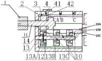
图2为本发明实施例中输送系统的剖面结构示意图;2 is a schematic cross-sectional structure diagram of a conveying system in an embodiment of the present invention;
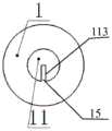
图3为本发明实施例中控弯旋钮与主动轴的截面示意图;3 is a schematic cross-sectional view of a bending control knob and a driving shaft in an embodiment of the present invention;
图4为本发明实施例中调节键的尺寸示意图FIG. 4 is a schematic diagram of the size of the adjustment key in the embodiment of the present invention
图5为本发明实施例中输送系统的局部剖面示意图;5 is a partial cross-sectional schematic diagram of the delivery system in the embodiment of the present invention;
图6为本发明实施例中主动齿轮与从动齿轮的配合关系示意图;6 is a schematic diagram of the cooperation relationship between the driving gear and the driven gear in the embodiment of the present invention;
图7为本发明实施例中固定轴、轴承和从动齿轮的截面示意图;7 is a schematic cross-sectional view of a fixed shaft, a bearing and a driven gear in an embodiment of the present invention;
图8为本发明实施例中输送外管上弯曲段的结构示意图;其中图8a为主视图,图8b为俯视图。FIG. 8 is a schematic structural diagram of the upper curved section of the conveying outer tube in an embodiment of the present invention; FIG. 8 a is a front view, and FIG. 8 b is a top view.
图中:In the picture:
1控弯旋钮 2箱体 3主动齿轮 4调节键1
5调节旋钮 6螺纹杆 7推进杆 8输送外管5 Adjustment knob 6 Threaded
9输送内管 10、10A、10B、10C 控弯线 12轴承9 Conveying
13、13A、13B、13C 从动齿轮 14固定轴 11主动轴13, 13A, 13B, 13C driven
41手持段 42行程段 71凸台 72推进杆主体41 Hand-held
111轴本体 112限位部件 21槽 113第一凹槽111
15第一凸起 81半环状构件15 The
具体实施方式Detailed ways
下面结合附图和实施例对本发明作进一步的描述。The present invention will be further described below with reference to the accompanying drawings and embodiments.
为了更加清楚地描述本发明的结构特征,采用“近端”、“远端”作为方位词,其中“近端”表示在手术过程中靠近操作者的一端;“远端”表示远离操作者的一端。术语“或”通常是以包括“和/或”的含义而进行使用的,除非内容另外明确指出外。图1为本发明实施例中输送系统的整体结构示意图,图2为本发明实施例中输送系统的剖面结构示意图。In order to describe the structural features of the present invention more clearly, "proximal end" and "distal end" are used as the orientation words, wherein "proximal end" means the end close to the operator during the operation; "distal end" means the end away from the operator one end. The term "or" is generally employed in its sense including "and/or" unless the content clearly dictates otherwise. FIG. 1 is a schematic diagram of the overall structure of a conveying system in an embodiment of the present invention, and FIG. 2 is a schematic diagram of a cross-sectional structure of the conveying system in an embodiment of the present invention.
请参见图1和图2,本实施例提供的输送系统包括手柄和输送导管,所述输送导管包括输送外管8和输送内管9,所述手柄包括控弯旋钮1、箱体2、主动齿轮3、调节键4、调节旋钮5、螺纹杆6、推进杆7、控弯线10、主动轴11、轴承12、从动齿轮13和固定轴14。Referring to FIGS. 1 and 2 , the delivery system provided in this embodiment includes a handle and a delivery catheter. The delivery catheter includes an
其中,主动轴11包括轴本体111和限位部件112,限位部件112位于轴本体111的远端,固定在轴本体111上。控弯旋钮1位于箱体2的外侧,与轴本体111同轴连接,套设在轴本体111的近端。一方面,控弯旋钮1需要带动主动轴11的旋转,另一方面主动轴11的轴向运动不受控弯旋钮1的限制。控弯旋钮1与主动轴11可以采用插接结构配合的形式来实现,插接结构可以为凹凸结构,例如,请参见图3,主动轴11的外壁设置有第一凹槽113,控弯旋钮1的内壁对应设置有与第一凹槽113相匹配的第一凸起15,可以满足两者在周向上协同转动,但是轴向运动互相不受影响。反之亦可,即主动轴11的外部设置第二凸起,控弯旋钮1的内部对应设置与第二凸起相匹配的第二凹槽。控弯旋钮1的形状,本实施例不做特别的限制,可以为圆柱状、圆台状、球缺状、球冠状等各种易于操作的形状。为了便于操作,控弯旋钮1的表面可以采用磨砂材料制成或者在控弯旋钮1的表面设置棱条、波浪等,以增加摩擦力,优化操作手感,对此,本实施例不做特别的限制。The driving
请继续参见图2,本实施例提供的手柄的主要传动部件位于箱体2的内部,主要传动部件包括主动齿轮3、调节旋钮5、控弯线10、主动轴11、轴承12、从动齿轮13和固定轴14。此外,调节旋钮5、螺纹杆6、推进杆7、输送外管8、输送内管9与箱体2同轴设置。调节旋钮5的外部尺寸小于箱体2的内部尺寸,以保证调节旋钮5可以在箱体2中自由转动。螺纹杆6、推进杆7和输送内管9一部分位于箱体2的内部,一部分延伸出箱体2;具体地,螺纹杆6的近端和推进杆7的近端位于箱体2内,螺纹杆6的远端和推进杆7的远端伸出箱体2外,输送内管9的近端贯穿螺纹杆6并与箱体2固定连接;输送外管8的近端与推进杆7固定连接,设置在箱体2外。Please continue to refer to FIG. 2 , the main transmission components of the handle provided in this embodiment are located inside the
主动齿轮3固定连接在轴本体111上,两者的连接方式本发明不做特别的限制,可以是过盈连接、键槽连接、螺钉连接、胶接等,主动轴11带动主动齿轮3周向运动和轴向移动。主动齿轮3、轴本体111和控弯旋钮1围绕同一中心轴设置。The
调节键4分为手持段41和行程段42两部分,调节键4的手持段41位于箱体2外表面的外部,调节键4的行程段42位于箱体2的内部。具体而言,箱体2的外壳上设置贯穿的槽21,手持段41卡接在槽21的外部,行程段42穿过槽21伸入到箱体2内,且行程段42的端部位于主动齿轮3和限位部件112之间,调节键4可以以槽21为轨道运动。槽21可以为直线型,也可以为曲线型。相对应的,调节键4可以做直线运动或曲线运动。对于调节键4的手持段41的形状,本发明没有特别的限制,可以为立方体、圆柱体、半圆体等,在槽21的宽度方向上,手持段41的尺寸应大于槽21的尺寸。调节键4的行程段42可以为长方体、圆柱体等,其长度应该保证行程段42的端部位于主动齿轮3和主动轴11的限位部件112之间,具体而言,请参见图4,行程段42的长度A2应该小于箱体2的外表面到主动轴11的距离A1,大于箱体2的外表面到主动齿轮3的外径的距离A4,且大于箱体2的外表面到限位部件112的外径的距离A3。The
请同时参见图5,当调节键4向限位部件112的方向运动时(运动方向是A→B的方向),调节键4的行程段42推动限位部件112,以带动主动轴11运动,从而带动主动齿轮3的轴向运动,对接相邻的从动齿轮(例如从从动齿轮13A拨到13B)。当调节键4向控弯旋钮1的方向运动时(运动方向是B→A的方向),调节键4的行程段42推动主动齿轮3运动,对接相邻的从动齿轮(例如从从动齿轮13B拨到13A)。请参见图6,主动轴11的轴本体111的长度L1应当大于第n个从动齿轮到箱体2的端面(靠近控弯旋钮1的端面)的距离L2,n为正整数。Please refer to FIG. 5 at the same time, when the
请参见图6,从动齿轮13位于主动齿轮3的一侧,可与主动齿轮3啮合,从动齿轮13通过轴承12安装在固定轴14上,从动齿轮13与固定轴14同轴,固定轴14位于箱体2内,与箱体2固定连接,连接方式可以是过盈连接、螺钉连接、胶接等。请参见图7,从内到外的部件依次为固定轴14、轴承12、从动齿轮13。根据控弯的需求(即控制几个方向的弯曲,1个从动齿轮对应一个方向),从动齿轮13的数量可以是1个、2个、3个或多个;较佳地,当从动齿轮13的数量为多个时,多个从动齿轮13依次排列在固定轴14上。利用轴承12连接从动齿轮13与固定轴14,使得每一个从动齿轮13可以独立地做周向运动,而相互不受影响,即主动齿轮3可分别与每个从动齿轮啮合,主动齿轮3与哪个从动齿轮啮合,哪个从动齿轮做周向运动,其他从动齿轮不动。根据控弯的要求,每个控弯方向采用同一固定轴14,对应一套控弯线10、轴承12、从动齿轮13。相对应地,编号为:10A、12A、13A、14为一组;10B、12B、13B、14为一组;10CB、12C、13C、14为一组……n个控弯方向对应n组,n为正整数。Please refer to FIG. 6 , the driven
请继续参见图2,调节旋钮5周向固定在螺纹杆6的近端,调节旋钮5和螺纹杆6之间的连接方式可以是过盈连接、键槽连接、螺钉连接、胶接等,调节旋钮5可以是圆柱体、立方体等各种易于操作的形状。推进杆7套设在螺纹杆6外围并与螺纹杆6通过螺纹连接,推进杆7分为两个部分,分别为推进杆主体72和限制推进杆7做周向运动的限位结构,限位结构可以为凸台71,推进杆主体72和凸台71一体制造或是固定连接,箱体外壳在凸台71对应的位置上设有与凸台71匹配的第三凹槽,凸台71和第三凹槽配合限制推进杆7做周向运动,输送外管8具有弯曲段,弯曲段的数量和位置根据需要进行设置,以n个弯曲段为例,对应的,从动齿轮13的数量为n个,控弯线10的数量为n根,控弯线10的n根线的一端分别设置在各个从动齿轮13的凹槽内,另一端分别与输送外管8的n个不同弯曲段连接。请参见图8,输送外管8的弯曲段可以沿着输送外管8的周向上设置半环状构件81,半环状构件81指周向只有半圆且轴向有间断沟槽的壁结构。图8给出了一种实施方式,半环状构件81处于输送外管8的外表面,控弯线10贯穿输送外管8的管壁,包括贯穿半环状构件81,最终固定在输送外管8的远端;在另一实施方式中,半环状构件81处于输送外管8的内表面,控弯线10处于输送外管8的内表面和输送内管9的外侧,此时控弯线10贯穿输送外管8的管壁,然后控弯线10贯穿半环状构件81,最终固定在输送外管8的远端内侧。1根控弯线10将多个半环状构件81串接起来,当控弯线10受拉时,输送外管弯曲段的半环状构件81相互贴合,使得输送外管8整体朝一侧弯曲。不同弯曲段上的半环状构件81可以沿不同半圆方向上设置,以控制不同的导管弯曲方向,如图8所示的分别设置在输送外管8的上半圆和下半圆,分别可以控制输送导管向上和向下弯曲,当然,输送外管8的弯曲段上不局限于设置半环状构件,可以是扇心角小于180度的扇形环状构件或者其它形状的构件。只要能够供控弯线10穿过串接,控制导管方向和弯曲度即可。当旋转调节旋钮5时,可使得输送外管8前进或后退,请参见图5,当调节键4置于A处时,转动控弯旋钮1时,控弯旋钮1带动主动轴11转动,进而带动主动齿轮3旋转,由于此时,主动齿轮3与从动齿轮13A啮合,从而带动从动齿轮13A旋转,当从动齿轮13A旋转时,由于控弯线10A固定在从动齿轮13A凹槽内,可将控弯线10A逐渐收紧在从动齿轮13内部,从而可控制特定段输送外管8朝指定方向弯曲。当调节键4移动到B处时,操作控弯旋钮1,可带动从动齿轮13B旋转,从而控制输送外管8的另一段朝另外一个方向弯曲。当调节键4移动到C处或n处,各部件的配合方式可类比A处/B处。Please continue to refer to FIG. 2, the adjustment knob 5 is circumferentially fixed at the proximal end of the threaded rod 6, and the connection between the adjustment knob 5 and the threaded rod 6 can be interference connection, keyway connection, screw connection, glue connection, etc. The adjustment knob 5 can be a cylinder, a cube and other easy-to-operate shapes. The
综上,本发明采用1个控弯旋钮1集成式地控制多个方向的导管弯曲,避免了1个控弯旋钮只能控制1个方向的弯曲,提高了可控弯手柄的可操作性,提高了手术精度。To sum up, the present invention adopts one
对于用于输送植入物的手柄来说,通常至少有两种旋钮,一种是控弯旋钮(控制弯曲度),一种是控制植入物释放的旋钮(控制轴向运动)。现有技术中,通过操作不同旋钮来控制导管以实现不同方向的控弯,对于高度紧张和精密的瓣膜置换手术来说,当手柄上排布很多旋钮时,很容易误操作。一方面,术者需要辨别,哪个旋钮是控弯,哪个旋钮是控制植入物的释放。另一方面,术者需要辨别,每个控弯旋钮分别对应哪个方向的控弯。这无疑增加了手术的操作难度。For handles used to deliver implants, there are usually at least two kinds of knobs, one is a bending control knob (controls the degree of curvature), and the other is a knob that controls the release of the implant (controls axial movement). In the prior art, the catheter is controlled by operating different knobs to control the bending in different directions. For highly stressful and precise valve replacement surgery, when many knobs are arranged on the handle, it is easy to misuse. On the one hand, the surgeon needs to identify which knob controls the bending and which knob controls the release of the implant. On the other hand, the surgeon needs to identify which direction each bend control knob corresponds to. This undoubtedly increases the difficulty of the operation.
对于本发明来说,两种旋钮分别设置一个,而控弯方向的选择通过调节键控制,并且,在操作时,每次只能控制一个方向,这就意味着,控制一个方向时,其他的方向被锁定,避免了多控弯旋钮并列时可能存在的误操作的情况,比如操作一个旋钮时,另外一个旋钮不小心被碰到。所以本发明提高了可控弯手柄的操作性和手术的精度。For the present invention, two kinds of knobs are provided with one respectively, and the selection of the bending direction is controlled by the adjustment key, and during operation, only one direction can be controlled at a time, which means that when one direction is controlled, the other The direction is locked to avoid possible misoperation when the multi-controller knobs are juxtaposed, such as when one knob is operated, the other knob is accidentally touched. Therefore, the present invention improves the operability of the controllable curved handle and the precision of the operation.
另外,本发明采用1个集成式的控弯旋钮相对于多旋钮,产品更加简约,轻量化。In addition, the present invention adopts one integrated bending control knob, compared with multiple knobs, the product is simpler and lighter.
现有技术中,每一个方向的控弯都需要对应使用一个控弯旋钮,由于控制旋钮需要手动操作,所以不宜做到很小,所以每增加一个控弯方向,就要增加一个控弯旋钮,即增加手柄的尺寸,当尺寸过大时,甚至需要多人操作。而对于本发明来说,仅采用一个控弯旋钮,使用调节键来对控弯旋钮进行“换挡”,每换一个档位,就可以控制一个方向的弯曲度。这样使得产品更加轻量化。In the prior art, a bending control knob needs to be used for each direction of the bending control. Since the control knob needs to be manually operated, it should not be made small. Therefore, every time a bending control direction is added, a bending control knob must be added. That is, the size of the handle is increased. When the size is too large, multiple people are required to operate it. For the present invention, only one bending control knob is used, and the adjustment key is used to "shift" the bending control knob, and the curvature in one direction can be controlled for each shift. This makes the product more lightweight.
虽然本发明已以较佳实施例揭示如上,然其并非用以限定本发明,任何本领域技术人员,在不脱离本发明的精神和范围内,当可作些许的修改和完善,因此本发明的保护范围当以权利要求书所界定的为准。Although the present invention has been disclosed above with preferred embodiments, it is not intended to limit the present invention. Any person skilled in the art can make some modifications and improvements without departing from the spirit and scope of the present invention. Therefore, the present invention The scope of protection shall be defined by the claims.
Claims (14)
Translated fromChinesePriority Applications (1)
| Application Number | Priority Date | Filing Date | Title |
|---|---|---|---|
| CN201910252879.1ACN111743663A (en) | 2019-03-29 | 2019-03-29 | A handle for delivering implants and its delivery system |
Applications Claiming Priority (1)
| Application Number | Priority Date | Filing Date | Title |
|---|---|---|---|
| CN201910252879.1ACN111743663A (en) | 2019-03-29 | 2019-03-29 | A handle for delivering implants and its delivery system |
Publications (1)
| Publication Number | Publication Date |
|---|---|
| CN111743663Atrue CN111743663A (en) | 2020-10-09 |
Family
ID=72672758
Family Applications (1)
| Application Number | Title | Priority Date | Filing Date |
|---|---|---|---|
| CN201910252879.1APendingCN111743663A (en) | 2019-03-29 | 2019-03-29 | A handle for delivering implants and its delivery system |
Country Status (1)
| Country | Link |
|---|---|
| CN (1) | CN111743663A (en) |
Cited By (3)
| Publication number | Priority date | Publication date | Assignee | Title |
|---|---|---|---|---|
| CN112957590A (en)* | 2020-12-31 | 2021-06-15 | 杭州诺茂医疗科技有限公司 | Ablation system, ablation device and adjustable-bending catheter |
| CN113397765A (en)* | 2021-07-15 | 2021-09-17 | 上海臻亿医疗科技有限公司 | Control handle, bending control line and implant conveying device |
| WO2023280329A1 (en)* | 2021-10-12 | 2023-01-12 | 江苏臻亿医疗科技有限公司 | Implant delivery handle, and delivery system and operating method therefor |
Citations (8)
| Publication number | Priority date | Publication date | Assignee | Title |
|---|---|---|---|---|
| US5395329A (en)* | 1994-01-19 | 1995-03-07 | Daig Corporation | Control handle for steerable catheter |
| CN202020777U (en)* | 2011-03-31 | 2011-11-02 | 先健科技(深圳)有限公司 | Adjustable bent catheter |
| CN205006941U (en)* | 2015-09-28 | 2016-02-03 | 宁波胜杰康生物科技有限公司 | Surgical instruments of adjustable turn of multistage |
| CN106264709A (en)* | 2015-05-29 | 2017-01-04 | 上海微创电生理医疗科技有限公司 | A kind of guiding catheter |
| CN106725994A (en)* | 2017-02-14 | 2017-05-31 | 公安部南昌警犬基地 | Dog spermatic device in portable visible uterine cavity |
| CN107496055A (en)* | 2017-08-10 | 2017-12-22 | 上海微创心通医疗科技有限公司 | Heart valve delivery catheter and induction system |
| CN108261256A (en)* | 2016-12-31 | 2018-07-10 | 先健科技(深圳)有限公司 | Conveying device and transport system |
| CN210130975U (en)* | 2019-03-29 | 2020-03-10 | 上海微创心通医疗科技有限公司 | Handle for conveying implant and conveying system thereof |
- 2019
- 2019-03-29CNCN201910252879.1Apatent/CN111743663A/enactivePending
Patent Citations (8)
| Publication number | Priority date | Publication date | Assignee | Title |
|---|---|---|---|---|
| US5395329A (en)* | 1994-01-19 | 1995-03-07 | Daig Corporation | Control handle for steerable catheter |
| CN202020777U (en)* | 2011-03-31 | 2011-11-02 | 先健科技(深圳)有限公司 | Adjustable bent catheter |
| CN106264709A (en)* | 2015-05-29 | 2017-01-04 | 上海微创电生理医疗科技有限公司 | A kind of guiding catheter |
| CN205006941U (en)* | 2015-09-28 | 2016-02-03 | 宁波胜杰康生物科技有限公司 | Surgical instruments of adjustable turn of multistage |
| CN108261256A (en)* | 2016-12-31 | 2018-07-10 | 先健科技(深圳)有限公司 | Conveying device and transport system |
| CN106725994A (en)* | 2017-02-14 | 2017-05-31 | 公安部南昌警犬基地 | Dog spermatic device in portable visible uterine cavity |
| CN107496055A (en)* | 2017-08-10 | 2017-12-22 | 上海微创心通医疗科技有限公司 | Heart valve delivery catheter and induction system |
| CN210130975U (en)* | 2019-03-29 | 2020-03-10 | 上海微创心通医疗科技有限公司 | Handle for conveying implant and conveying system thereof |
Cited By (4)
| Publication number | Priority date | Publication date | Assignee | Title |
|---|---|---|---|---|
| CN112957590A (en)* | 2020-12-31 | 2021-06-15 | 杭州诺茂医疗科技有限公司 | Ablation system, ablation device and adjustable-bending catheter |
| CN112957590B (en)* | 2020-12-31 | 2022-09-27 | 杭州德诺电生理医疗科技有限公司 | Ablation system, ablation device and bendable catheter |
| CN113397765A (en)* | 2021-07-15 | 2021-09-17 | 上海臻亿医疗科技有限公司 | Control handle, bending control line and implant conveying device |
| WO2023280329A1 (en)* | 2021-10-12 | 2023-01-12 | 江苏臻亿医疗科技有限公司 | Implant delivery handle, and delivery system and operating method therefor |
Similar Documents
| Publication | Publication Date | Title |
|---|---|---|
| US12178973B2 (en) | Apparatus for the introduction and manipulation of multiple telescoping catheters | |
| CN111743663A (en) | A handle for delivering implants and its delivery system | |
| EP3005983B1 (en) | Electric handle for implant delivery and delivery system | |
| CN109223064A (en) | A kind of operation handle and adjustable bending sheath tube of adjustable bending sheath tube | |
| JP2011529731A (en) | Method and system for long term adjustment of implantable devices | |
| WO2019128653A1 (en) | Medical appliance deployment apparatus | |
| CN114305807B (en) | Tricuspid valve repair device | |
| CN207613786U (en) | A kind of ultrasonic probe pose adjusting apparatus | |
| CN217366195U (en) | Adjustable bent sheath tube | |
| WO2021043022A1 (en) | Medical implant conveying device | |
| WO2023017443A2 (en) | Catheter handle with a locking mechanism | |
| CN113616380A (en) | Implant delivery handle, implant system, delivery system and working method thereof | |
| WO2020200149A1 (en) | Drive handle used for delivering implant and delivery system | |
| CN109480922A (en) | A kind of remote center movement parallel institution of four-degree-of-freedom for Minimally Invasive Surgery | |
| CN209404841U (en) | A multi-degree-of-freedom minimally invasive surgical instrument | |
| CN210130975U (en) | Handle for conveying implant and conveying system thereof | |
| CN112137781A (en) | Handle and delivery system | |
| CN212347421U (en) | Bending control handle for conveying implant and conveying system thereof | |
| CN113244501A (en) | Bending control handle for conveying implant and conveying system thereof | |
| CN113813081B (en) | A controlled release device on an implant prosthesis delivery system | |
| CN117653882B (en) | A guide catheter with adjustable diameter | |
| US20240366375A1 (en) | Implant delivery device and implant delivery system | |
| CN113545891A (en) | A Novel Transcatheter Valve Delivery System | |
| CN119587223A (en) | Self-forming artificial valve ring delivery device | |
| CN116510156A (en) | Compact structure's control handle |
Legal Events
| Date | Code | Title | Description |
|---|---|---|---|
| PB01 | Publication | ||
| PB01 | Publication | ||
| SE01 | Entry into force of request for substantive examination | ||
| SE01 | Entry into force of request for substantive examination | ||
| WD01 | Invention patent application deemed withdrawn after publication | ||
| WD01 | Invention patent application deemed withdrawn after publication | Application publication date:20201009 |