CN111742356B - Detection system - Google Patents
Detection systemDownload PDFInfo
- Publication number
- CN111742356B CN111742356BCN201880089995.XACN201880089995ACN111742356BCN 111742356 BCN111742356 BCN 111742356BCN 201880089995 ACN201880089995 ACN 201880089995ACN 111742356 BCN111742356 BCN 111742356B
- Authority
- CN
- China
- Prior art keywords
- vehicle
- coil
- trajectory
- image
- receiving coil
- Prior art date
- Legal status (The legal status is an assumption and is not a legal conclusion. Google has not performed a legal analysis and makes no representation as to the accuracy of the status listed.)
- Active
Links
Images


Classifications
- G—PHYSICS
- G01—MEASURING; TESTING
- G01D—MEASURING NOT SPECIALLY ADAPTED FOR A SPECIFIC VARIABLE; ARRANGEMENTS FOR MEASURING TWO OR MORE VARIABLES NOT COVERED IN A SINGLE OTHER SUBCLASS; TARIFF METERING APPARATUS; MEASURING OR TESTING NOT OTHERWISE PROVIDED FOR
- G01D5/00—Mechanical means for transferring the output of a sensing member; Means for converting the output of a sensing member to another variable where the form or nature of the sensing member does not constrain the means for converting; Transducers not specially adapted for a specific variable
- G01D5/12—Mechanical means for transferring the output of a sensing member; Means for converting the output of a sensing member to another variable where the form or nature of the sensing member does not constrain the means for converting; Transducers not specially adapted for a specific variable using electric or magnetic means
- G01D5/14—Mechanical means for transferring the output of a sensing member; Means for converting the output of a sensing member to another variable where the form or nature of the sensing member does not constrain the means for converting; Transducers not specially adapted for a specific variable using electric or magnetic means influencing the magnitude of a current or voltage
- G01D5/20—Mechanical means for transferring the output of a sensing member; Means for converting the output of a sensing member to another variable where the form or nature of the sensing member does not constrain the means for converting; Transducers not specially adapted for a specific variable using electric or magnetic means influencing the magnitude of a current or voltage by varying inductance, e.g. by a movable armature
- G01D5/22—Mechanical means for transferring the output of a sensing member; Means for converting the output of a sensing member to another variable where the form or nature of the sensing member does not constrain the means for converting; Transducers not specially adapted for a specific variable using electric or magnetic means influencing the magnitude of a current or voltage by varying inductance, e.g. by a movable armature differentially influencing two coils
- G—PHYSICS
- G08—SIGNALLING
- G08G—TRAFFIC CONTROL SYSTEMS
- G08G1/00—Traffic control systems for road vehicles
- G08G1/01—Detecting movement of traffic to be counted or controlled
- G08G1/015—Detecting movement of traffic to be counted or controlled with provision for distinguishing between two or more types of vehicles, e.g. between motor-cars and cycles
- B—PERFORMING OPERATIONS; TRANSPORTING
- B61—RAILWAYS
- B61L—GUIDING RAILWAY TRAFFIC; ENSURING THE SAFETY OF RAILWAY TRAFFIC
- B61L1/00—Devices along the route controlled by interaction with the vehicle or train
- B61L1/02—Electric devices associated with track, e.g. rail contacts
- B61L1/08—Electric devices associated with track, e.g. rail contacts magnetically actuated; electrostatically actuated
- G—PHYSICS
- G01—MEASURING; TESTING
- G01P—MEASURING LINEAR OR ANGULAR SPEED, ACCELERATION, DECELERATION, OR SHOCK; INDICATING PRESENCE, ABSENCE, OR DIRECTION, OF MOVEMENT
- G01P13/00—Indicating or recording presence, absence, or direction, of movement
- G01P13/02—Indicating direction only, e.g. by weather vane
- G—PHYSICS
- G01—MEASURING; TESTING
- G01V—GEOPHYSICS; GRAVITATIONAL MEASUREMENTS; DETECTING MASSES OR OBJECTS; TAGS
- G01V3/00—Electric or magnetic prospecting or detecting; Measuring magnetic field characteristics of the earth, e.g. declination, deviation
- G01V3/08—Electric or magnetic prospecting or detecting; Measuring magnetic field characteristics of the earth, e.g. declination, deviation operating with magnetic or electric fields produced or modified by objects or geological structures or by detecting devices
- G01V3/10—Electric or magnetic prospecting or detecting; Measuring magnetic field characteristics of the earth, e.g. declination, deviation operating with magnetic or electric fields produced or modified by objects or geological structures or by detecting devices using induction coils
- G01V3/104—Electric or magnetic prospecting or detecting; Measuring magnetic field characteristics of the earth, e.g. declination, deviation operating with magnetic or electric fields produced or modified by objects or geological structures or by detecting devices using induction coils using several coupled or uncoupled coils
- G01V3/105—Electric or magnetic prospecting or detecting; Measuring magnetic field characteristics of the earth, e.g. declination, deviation operating with magnetic or electric fields produced or modified by objects or geological structures or by detecting devices using induction coils using several coupled or uncoupled coils forming directly coupled primary and secondary coils or loops
- G01V3/107—Electric or magnetic prospecting or detecting; Measuring magnetic field characteristics of the earth, e.g. declination, deviation operating with magnetic or electric fields produced or modified by objects or geological structures or by detecting devices using induction coils using several coupled or uncoupled coils forming directly coupled primary and secondary coils or loops using compensating coil or loop arrangements
- G—PHYSICS
- G01—MEASURING; TESTING
- G01V—GEOPHYSICS; GRAVITATIONAL MEASUREMENTS; DETECTING MASSES OR OBJECTS; TAGS
- G01V3/00—Electric or magnetic prospecting or detecting; Measuring magnetic field characteristics of the earth, e.g. declination, deviation
- G01V3/38—Processing data, e.g. for analysis, for interpretation, for correction
- G—PHYSICS
- G06—COMPUTING OR CALCULATING; COUNTING
- G06T—IMAGE DATA PROCESSING OR GENERATION, IN GENERAL
- G06T7/00—Image analysis
- G06T7/20—Analysis of motion
- G06T7/246—Analysis of motion using feature-based methods, e.g. the tracking of corners or segments
- G06T7/248—Analysis of motion using feature-based methods, e.g. the tracking of corners or segments involving reference images or patches
- G—PHYSICS
- G08—SIGNALLING
- G08G—TRAFFIC CONTROL SYSTEMS
- G08G1/00—Traffic control systems for road vehicles
- G08G1/01—Detecting movement of traffic to be counted or controlled
- G08G1/042—Detecting movement of traffic to be counted or controlled using inductive or magnetic detectors
- G—PHYSICS
- G08—SIGNALLING
- G08G—TRAFFIC CONTROL SYSTEMS
- G08G1/00—Traffic control systems for road vehicles
- G08G1/01—Detecting movement of traffic to be counted or controlled
- G08G1/056—Detecting movement of traffic to be counted or controlled with provision for distinguishing direction of travel
- G—PHYSICS
- G01—MEASURING; TESTING
- G01V—GEOPHYSICS; GRAVITATIONAL MEASUREMENTS; DETECTING MASSES OR OBJECTS; TAGS
- G01V3/00—Electric or magnetic prospecting or detecting; Measuring magnetic field characteristics of the earth, e.g. declination, deviation
- G01V3/08—Electric or magnetic prospecting or detecting; Measuring magnetic field characteristics of the earth, e.g. declination, deviation operating with magnetic or electric fields produced or modified by objects or geological structures or by detecting devices
- G01V3/10—Electric or magnetic prospecting or detecting; Measuring magnetic field characteristics of the earth, e.g. declination, deviation operating with magnetic or electric fields produced or modified by objects or geological structures or by detecting devices using induction coils
- G01V3/104—Electric or magnetic prospecting or detecting; Measuring magnetic field characteristics of the earth, e.g. declination, deviation operating with magnetic or electric fields produced or modified by objects or geological structures or by detecting devices using induction coils using several coupled or uncoupled coils
- G01V3/105—Electric or magnetic prospecting or detecting; Measuring magnetic field characteristics of the earth, e.g. declination, deviation operating with magnetic or electric fields produced or modified by objects or geological structures or by detecting devices using induction coils using several coupled or uncoupled coils forming directly coupled primary and secondary coils or loops
- G—PHYSICS
- G06—COMPUTING OR CALCULATING; COUNTING
- G06T—IMAGE DATA PROCESSING OR GENERATION, IN GENERAL
- G06T2207/00—Indexing scheme for image analysis or image enhancement
- G06T2207/30—Subject of image; Context of image processing
- G06T2207/30241—Trajectory
- G—PHYSICS
- G06—COMPUTING OR CALCULATING; COUNTING
- G06T—IMAGE DATA PROCESSING OR GENERATION, IN GENERAL
- G06T2207/00—Indexing scheme for image analysis or image enhancement
- G06T2207/30—Subject of image; Context of image processing
- G06T2207/30248—Vehicle exterior or interior
- G06T2207/30252—Vehicle exterior; Vicinity of vehicle
- G—PHYSICS
- G06—COMPUTING OR CALCULATING; COUNTING
- G06V—IMAGE OR VIDEO RECOGNITION OR UNDERSTANDING
- G06V20/00—Scenes; Scene-specific elements
- G06V20/50—Context or environment of the image
- G06V20/52—Surveillance or monitoring of activities, e.g. for recognising suspicious objects
Landscapes
- Physics & Mathematics (AREA)
- General Physics & Mathematics (AREA)
- Engineering & Computer Science (AREA)
- Life Sciences & Earth Sciences (AREA)
- Remote Sensing (AREA)
- General Life Sciences & Earth Sciences (AREA)
- Geology (AREA)
- Environmental & Geological Engineering (AREA)
- Geophysics (AREA)
- Electromagnetism (AREA)
- Multimedia (AREA)
- Computer Vision & Pattern Recognition (AREA)
- Theoretical Computer Science (AREA)
- Mechanical Engineering (AREA)
- Automation & Control Theory (AREA)
- Traffic Control Systems (AREA)
- Geophysics And Detection Of Objects (AREA)
Abstract
Description
Translated fromChinese技术领域technical field
本发明涉及检测系统及监控系统,例如涉及检测车辆的检测系统。The present invention relates to detection systems and monitoring systems, such as detection systems for detecting vehicles.
背景技术Background technique
作为判别特定的车辆的方法,已知:向车辆照射激光,根据所获得的距离信息判别车辆形状并提取特定车辆的技术;将利用照相机拍摄的图像二值化,通过背景差分等处理提取特定车辆的技术。这样的技术一般根据所得到的车辆形状信息进行车种判别,并且,通过帧间差分判别车辆行进方向。这样,在使用光的技术中,干扰光的光量变动、车辆涂漆颜色、雾引起的能见距离降低、由于雨而产生的光的散射等,导致车种判别精度降低,在户外环境中使用存在技术上的课题。As a method of identifying a specific vehicle, there are known techniques for irradiating the vehicle with laser light, identifying the shape of the vehicle based on the obtained distance information, and extracting the specific vehicle; binarizing the image captured by the camera, and extracting the specific vehicle by processing such as background difference. Technology. Such a technique generally discriminates the vehicle type based on the obtained vehicle shape information, and discriminates the traveling direction of the vehicle by the difference between frames. In the technology using light in this way, fluctuations in the amount of disturbing light, vehicle paint color, reduction in visibility due to fog, light scattering due to rain, etc., reduce the accuracy of vehicle type discrimination, and are used in outdoor environments. There are technical issues.
对于这样的课题,也提出了利用磁性的技术(例如,参照专利文献1)。专利文献1中公开的技术中,在车辆行驶轴方向和车辆相向轴方向设置X轴、Y轴测量用的磁性传感器两个,检测出车辆所保持的固有磁场值。将磁性传感器的X轴输出和Y轴输出的结果变换为R(电平)和相位值,根据相位变化是右旋还是左旋判定车辆行进方向,并且根据R(电平)的大小判定车辆尺寸来进行车辆种类判别。For such a subject, a technique using magnetism has also been proposed (for example, refer to Patent Document 1). In the technique disclosed in
另外,也已知有利用电磁感应的技术(例如,参照专利文献2)。专利文献2中公开的技术中,设置环线线圈,并检测车辆通过时的与车辆底部之间的耦合状态的差,由此例如进行大型卡车、二吨卡车、乘用车的类别判定。In addition, a technique using electromagnetic induction is also known (for example, refer to Patent Document 2). In the technique disclosed in
现有技术文献prior art literature
专利文献Patent Literature
专利文献1:日本特开平10-172093号公报Patent Document 1: Japanese Patent Application Laid-Open No. 10-172093
专利文献2:日本特开平4-100200号公报Patent Document 2: Japanese Patent Application Laid-Open No. 4-100200
发明内容SUMMARY OF THE INVENTION
发明要解决的问题Invention to solve problem
然而,在专利文献1的磁性传感器方式的技术中,有能够根据车辆的磁化状态差检测出特定车辆的可能性,但是,磁性传感器方式不能在铁路沿线、道口周围等电磁噪声环境下实用。另外,在高速道路等车辆以比较固定速度通过的场所中有利用可能性,但是,如普通道路那样,存在以下课题:在由于拥堵车辆多辆相连而停止的状态下,磁性传感器的输出值变大,而在车少的清净状态下,磁性传感器的输出值变小。另外,由于是检测直流磁场的方式,因此,存在:根据车辆通过速度不同,输出也变化,对实用带来限制的课题。However, in the technology of the magnetic sensor method of
另外,在专利文献2的环线线圈方式的技术中,由于是检测环线线圈的电感变化的方式,因此,检测分辨率决定于环线线圈的尺寸。对于环线线圈方式,如众所周知,需要一定大小以上的尺寸,因此,是在大致的尺寸范围能够辨别车辆的种类的水平,为了提取特定车辆(公共汽车或维护车辆、货物车辆等),需要在车辆搭载无线设备、GPS接收机、ID标签等,通过与地面设备之间的数据收发,检测特定车辆。In addition, in the technique of the loop coil method of
本发明是鉴于以上那样的状况而完成的,其目的在于,提供解决上述课题的技术。The present invention has been made in view of the above-mentioned circumstances, and an object of the present invention is to provide a technique for solving the above-mentioned problems.
解决问题的方案solution to the problem
本发明的检测系统具备:电磁感应传感器,其具备发送线圈、和差动连接的第一接收线圈及第二接收线圈;轨迹图像输出部,其在以接收电平和相位差表示的坐标系中按时间序列绘制所述第一接收线圈和所述第二接收线圈的检测波形,并作为轨迹图像进行输出;以及交通工具检测部,其基于所述轨迹图像,检测交通工具在设置有所述电磁感应传感器的区域中通过这一情况。The detection system of the present invention includes: an electromagnetic induction sensor including a transmitting coil, a first receiving coil and a second receiving coil that are differentially connected; Time-series plotting of the detection waveforms of the first receiving coil and the second receiving coil, and outputting as a trajectory image; and a vehicle detection unit for detecting, based on the trajectory image, that a vehicle is provided with the electromagnetic induction This situation is passed in the area of the sensor.
另外,也可以具备:登记部,其预先登记设为检测对象的交通工具的轨迹图像作为参照图像;以及判定部,其对所述参照图像和从所述轨迹图像输出部输出的所述轨迹图像进行比较,来判定是否是已经登记的交通工具。Further, a registration unit may be provided which registers, as a reference image, a trajectory image of a vehicle to be detected in advance, and a determination unit which compares the reference image and the trajectory image output from the trajectory image output unit. A comparison is made to determine whether it is a registered vehicle.
另外,也可以,所述交通工具检测部基于所述轨迹图像的轨迹方向,判断所述交通工具的行进方向。In addition, the vehicle detection unit may determine the traveling direction of the vehicle based on the trajectory direction of the trajectory image.
本发明的检测系统具备:电磁感应传感器,其具备发送线圈、和差动连接的第一接收线圈及第二接收线圈;以及判定部,其在以接收电平和相位差表示的坐标系中按时间序列输出所述第一接收线圈和所述第二接收线圈的检测波形,并提取输出结果的特征,由此对交通工具进行判定。The detection system of the present invention includes: an electromagnetic induction sensor including a transmitting coil, a first receiving coil and a second receiving coil that are differentially connected; The detection waveforms of the first receiving coil and the second receiving coil are output in sequence, and the features of the output results are extracted, thereby determining the vehicle.
发明效果Invention effect
根据本发明,在提取特定车辆时,不用在车辆搭载无线设备、GPS、ID标签等通过与地面设备之间的数据收发来提取特定车辆,而能够根据设置于地面的电磁感应传感器检测到车辆的波形轨迹的结果,提取特定车辆,并且判定车辆行进方向。According to the present invention, when extracting a specific vehicle, it is not necessary to install a wireless device, GPS, ID tag, etc. on the vehicle to extract the specific vehicle through data transmission and reception with ground equipment, and the electromagnetic induction sensor installed on the ground can detect the vehicle's location. As a result of the waveform trace, a specific vehicle is extracted, and the direction of travel of the vehicle is determined.
附图说明Description of drawings
图1是对本实施方式涉及的利用电磁感应传感器检测车辆的车辆底部的例进行说明的图。FIG. 1 is a diagram illustrating an example in which the vehicle bottom of the vehicle is detected by the electromagnetic induction sensor according to the present embodiment.
图2是表示本实施方式涉及的在车辆检测的试验中使用的检测系统的构成例的图。FIG. 2 is a diagram showing a configuration example of a detection system used in a vehicle detection test according to the present embodiment.
图3是对本实施方式涉及的当在传感器部(发送线圈、第一接收线圈、第二接收线圈)通过的情况下利用数据记录器得到的数据的轨迹进行说明的图。FIG. 3 is a diagram illustrating the locus of data obtained by the data recorder when the sensor units (transmitting coil, first receiving coil, and second receiving coil) according to the present embodiment pass through.
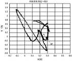
图4是表示本实施方式涉及的单箱车的X、Y轨迹的图。FIG. 4 is a diagram showing X and Y trajectories of the single-cartridge according to the present embodiment.
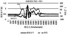
图5是表示本实施方式涉及的将关于单箱车收集到的时间序列X、Y数据变换为接收电平和相位值并设为时间序列的数据的图。FIG. 5 is a diagram showing time-series X and Y data collected on a single-cartridge vehicle according to the present embodiment, converted into reception level and phase values, and set as time-series data.
图6是表示本实施方式涉及的单箱车的X、Y轨迹的图。FIG. 6 is a diagram showing X and Y trajectories of the single-cartridge according to the present embodiment.
图7是表示本实施方式涉及的将关于单箱车收集到的时间序列X、Y数据变换为接收电平和相位值并设为时间序列的数据的图。FIG. 7 is a diagram showing time-series X and Y data collected on a single-cargo vehicle according to the present embodiment, converted into reception level and phase values, and set as time-series data.
图8是表示本实施方式涉及的2t卡车的X、Y轨迹的图。FIG. 8 is a diagram showing X and Y trajectories of the 2t truck according to the present embodiment.
图9是表示本实施方式涉及的将关于2t卡车收集到的时间序列X、Y数据变换为接收电平和相位值并设为时间序列的数据的图。FIG. 9 is a diagram showing time-series X and Y data collected on a 2t truck according to the present embodiment, converted into reception level and phase values, and set as time-series data.
图10是表示本实施方式涉及的2t卡车的X、Y轨迹的图。FIG. 10 is a diagram showing the X and Y trajectories of the 2t truck according to the present embodiment.
图11是表示本实施方式涉及的将关于2t卡车收集到的时间序列X、Y数据变换为接收电平和相位值并设为时间序列的数据的图。FIG. 11 is a diagram showing time-series X and Y data collected on a 2t truck according to the present embodiment, converted into reception level and phase values, and set as time-series data.
图12是表示本实施方式涉及的轨迹判定方法的一例的流程图。FIG. 12 is a flowchart showing an example of the trajectory determination method according to the present embodiment.
图13是表示本实施方式涉及的适用于监控对象区域(施工现场等的安全监控)的监控系统的图。FIG. 13 is a diagram showing a monitoring system applied to a monitoring target area (safety monitoring of a construction site or the like) according to the present embodiment.
图14是本实施方式涉及的监控系统的概略方框图。FIG. 14 is a schematic block diagram of the monitoring system according to the present embodiment.
具体实施方式Detailed ways
接着,参照附图对用于实施本发明的形态(以下,简称为“实施方式”)具体地进行说明。本实施方式的概要如下。即,Next, an aspect for implementing the present invention (hereinafter, simply referred to as an "embodiment") will be specifically described with reference to the drawings. The outline of this embodiment is as follows. which is,
(1)特定车辆的提取手段(1) Extraction method for a specific vehicle
将电磁感应传感器设置于车辆检测范围内。获得在直角坐标系中表示出电磁感应传感器检测到车辆时的检测波形的轨迹图像。对所获得的检测波形的轨迹图像、和预先进行数据登记的每个车种的检测波形的轨迹图像(即“参照图像”)进行比较对照。比较对照中,利用图像匹配的程度进行判定。由此,不只是车辆判别,也进行车种判别(特定车辆的提取)。Set the electromagnetic induction sensor within the vehicle detection range. A trajectory image is obtained that represents the detected waveform when the electromagnetic induction sensor detects the vehicle in the rectangular coordinate system. The obtained trace image of the detected waveform is compared with the trace image of the detected waveform of each vehicle type (ie, "reference image") for which data registration has been performed in advance. In the comparison and comparison, the judgment is made based on the degree of image matching. Thereby, not only vehicle identification but also vehicle type identification (extraction of a specific vehicle) is performed.
(2)特定车辆的行进方向判定手段(2) Means for determining the direction of travel of a specific vehicle
通过判定电磁感应传感器检测到车辆时的轨迹图像的轨迹方向,来对车辆行进方向进行判定。轨迹方向的判定中,在将轨迹图像化时,在从轨迹起点到结束为止的期间,设置灰度或对比度差。将设置了灰度或对比度差的图像数据通过图像处理,判定从轨迹开始到结束为止的轨迹方向。The traveling direction of the vehicle is determined by determining the trajectory direction of the trajectory image when the electromagnetic induction sensor detects the vehicle. In the determination of the track direction, when the track is imaged, a gradation or contrast difference is set during the period from the start point to the end of the track. The image data in which the gradation or contrast difference is set is subjected to image processing, and the track direction from the track start to the end is determined.
<基本技术><Basic Technology>
首先,对使用了电磁感应传感器的车种判别的基本技术进行说明。电磁感应传感器利用在金属材料中产生的涡电流作用,能够适用于专门利用于金属材料的距离测量用途或金属类别判定用途。车种判别是以下机制:利用电磁感应传感器获得按每个由金属构成的车辆产生的由于形状不同导致的距离差异信息、每个车辆构成的金属差异的信息,来进行车种判别。First, the basic technology of vehicle type discrimination using an electromagnetic induction sensor will be described. The electromagnetic induction sensor utilizes the action of eddy currents generated in metal materials, and can be suitable for distance measurement applications or metal type determination applications that are exclusively used for metal materials. The vehicle type discrimination is a mechanism for discriminating the vehicle type by obtaining information on distance differences due to differences in shape for each vehicle made of metal and information on metal differences in each vehicle using an electromagnetic induction sensor.
下面,利用最佳实施方式的图1进行说明。图1中,表示利用电磁感应传感器检测车辆90的车辆底部92的例。作为电磁感应传感器的传感器部10具备发送线圈TX1、第一接收线圈RX1、和第二接收线圈RX2。Next, description will be made using FIG. 1 of the best embodiment. In FIG. 1, the example in which the vehicle bottom part 92 of the
将发送线圈TX1与第一接收线圈RX1的线圈间距离L1、和发送线圈TX1与第二接收线圈RX2的线圈间距离L2,设置为等距离。传感器部10以这样的结构埋设于道路。在该状态下,若向发送线圈TX1供给频率f0的发送电流I,则从发送线圈TX1发射交变磁场。在以等距离设置的第一接收线圈RX1和第二接收线圈RX2中感应的电压分别是相同的电平,在图1中输出的差动输出值(差动输出信号)是大致0V状态。该状态是未检测出车辆的定常状态(车辆未检测到状态)。The inter-coil distance L1 between the transmitting coil TX1 and the first receiving coil RX1 and the inter-coil distance L2 between the transmitting coil TX1 and the second receiving coil RX2 are set to be equal distances. The
若从车辆未检测到状态车辆90在传感器部10的正上方通过,则根据图1所示的机制,输出按每个车辆90而不同的检测波形,作为差动输出信号。具体地,发送线圈TX1的发射磁场被作为钢材的车辆90的磁场吸引(S1)。When the
若车辆90靠近,则从图中用虚线表示的状态1向用点划线表示的状态2变化(S2)。由于成为状态2的磁场,从而在接收线圈(在此,第一接收线圈RX1)中贯穿的磁场与线圈交错。另外,也伴随涡电流的退磁场作用,在第一接收线圈RX1中贯穿的磁场减少。另外,涡电流的作用也伴随相位变化。When the
相对于第一接收线圈RX1的状态1的磁场时(车辆未检测到时)的感应电压,发生感应电压降低和相位变化(S3)。With respect to the induced voltage at the time of the magnetic field of the first receiving coil RX1 in state 1 (when the vehicle is not detected), the induced voltage decreases and the phase changes ( S3 ).
接着,第二接收线圈RX2与第一接收线圈RX1的差动输出信号随着车辆行进而配合车辆底部92的凹凸或金属类别发生变化(S4)。这样,得到按每个车辆而不同的检测波形,从而,不只是车辆判别,也能够进行车种判别。Next, the differential output signals of the second receiving coil RX2 and the first receiving coil RX1 change as the vehicle travels to match the unevenness or metal type of the vehicle bottom 92 ( S4 ). In this way, detection waveforms that differ for each vehicle are obtained, so that not only vehicle identification but also vehicle type identification can be performed.
下面,示出将第一接收线圈RX1和第二接收线圈RX2设为差动连接的优点。本方式中,由于差动连接,因此基于温度变化的线圈的电感变化在第一接收线圈RX1和第二接收线圈RX2中相同,且通过差动连接被消除。另外,即使由于发送线圈TX1的电感变化使得发射磁场强度发生变化,由于差动连接,因此第一接收线圈RX1的感应电压和第二接收线圈RX2的感应电压都减少,差动输出结果没有变化。即,即使外部环境发生温度变化,定常时的检测输出也不变化而是稳定值。因此,通过将第一接收线圈RX1和第二接收线圈RX2设为差动连接,从而能够灵敏度良好地只检测车辆底部92的凹凸状态。另外,即使在铁路沿线或道口周围等电磁噪声环境下,也由于将第一接收线圈RX1和第二接收线圈RX2之间设为了差动连接,因此成为所谓的共模噪声,对输出波形没有影响。即,通过采用本方式,不用改变用于避开电磁噪声源的滤波器或频率f0,而能够运用。Next, the advantage of making the first receiving coil RX1 and the second receiving coil RX2 differentially connected will be described. In this aspect, since the differential connection is used, the change in inductance of the coil due to the temperature change is the same in the first receiving coil RX1 and the second receiving coil RX2, and is canceled by the differential connection. In addition, even if the transmission magnetic field strength changes due to the change in the inductance of the transmission coil TX1, the induced voltage of the first receiving coil RX1 and the induced voltage of the second receiving coil RX2 are reduced due to the differential connection, and the differential output result does not change. That is, even if the temperature of the external environment changes, the detection output in the steady state does not change but is a stable value. Therefore, by connecting the first receiving coil RX1 and the second receiving coil RX2 differentially, only the unevenness of the vehicle bottom 92 can be detected with high sensitivity. In addition, even in an electromagnetic noise environment such as along a railway line or around a crossing, since the first receiving coil RX1 and the second receiving coil RX2 are differentially connected, so-called common mode noise is generated and has no effect on the output waveform. . That is, by adopting this method, it is possible to operate without changing the filter or frequency f0 for avoiding the electromagnetic noise source.
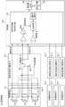
下面,对具体的车辆检测例(车种判别例)的试验结果进行说明。图2示出试验中使用的检测系统1的构成例。在此使用的检测系统1由上述的传感器部10、接收发送放大器部20、信号处理部30、和数据记录器40构成。信号处理部30是所谓的锁定放大器。Next, the test results of a specific vehicle detection example (vehicle type discrimination example) will be described. FIG. 2 shows a configuration example of the
接收发送放大器部20中,从功率放大器向传感器部10的发送线圈TX1施加频率f0的交流电流。由此,交变磁场被输出。将频率f0的发送信号、和第一接收线圈RX1与第二接收线圈RX2之间的差动输出结果,向作为锁定放大器的信号处理部30输入。信号处理部30将运算处理结果的极坐标系的X坐标和Y坐标向数据记录器40输出。数据记录器40在每5ms对来自信号处理部30的输出结果进行收集。In the reception/
参照图3,对在使车辆向第一接收线圈RX1→第二接收线圈RX2方向通过的情况、使车辆向第二接收线圈RX2→第一接收线圈RX1方向通过的情况下,由数据记录器40得到的数据的轨迹进行说明。对于埋设于路面的传感器部10,在图中,在左侧配置了第一接收线圈RX1,在右侧配置了第二接收线圈RX2,在中央配置了发送线圈TX1。Referring to FIG. 3 , in the case of passing the vehicle in the direction of the first receiving coil RX1→the second receiving coil RX2, and in the case of passing the vehicle in the direction of the second receiving coil RX2→the first receiving coil RX1, the
状态1是在传感器部10的左侧存在车辆90的车辆未检测到状态A。状态2是车辆90的右侧车轮存在于第一接收线圈RX1与发送线圈TX1之间的车辆检测到状态A。The
状态3是车辆90的左侧车轮存在于第二接收线圈RX2与发送线圈TX1之间的车辆检测到状态B。状态4是在传感器部10的右侧存在车辆90的车辆未检测到状态B。
在状态1下,接收信号是电平R0,相对于发送信号错开相位θ1,在X、Y坐标系中,绘制于坐标<1>(X0、Y0)。In
在状态2下,接收信号是电平R1,相对于发送信号错开相位θ2,在X、Y坐标系中,绘制于坐标<2>(X1、Y1)。随着车辆90从状态1向状态2转变,所绘制的点从坐标<1>向<2>,如图示那样描绘出圆弧A1。In
在状态3下,接收信号是电平R2,相对于发送信号错开相位θ3(在此,相位差0),在X、Y坐标系中,绘制于坐标<3>(X1、Y1)。随着车辆90从状态2向状态3转变,所绘制的点从坐标<2>向<3>,如图示那样描绘出圆弧A2。In
在状态4下,返回到与状态1相同的状态,接收信号是电平R0,相对于发送信号错开相位θ1,在X、Y坐标系中,绘制于坐标<4>(X0、Y0)。随着车辆90从状态3向状态4转变,所绘制的点从坐标<3>向<4>,如图示那样描绘出圆弧A3。In state 4, the state returns to the same state as in
在使车辆90向RX1→RX2方向通过的情况、和使车辆90向RX2→RX1方向通过的情况下,绘制的轨迹(上述例中,圆弧A、B、C)以相反方向描绘。即,在车辆90向第一接收线圈RX1→第二接收线圈RX2的方向通过的情况下,按坐标<1>→<2>→<3>→<4>的顺序(圆弧A1→A2→A3的顺序),描绘轨迹。另外,在车辆90向第二接收线圈RX2→第一接收线圈RX1的方向通过的情况下,按坐标<4>→<3>→<2>→<1>的顺序(圆弧A3→A2→A1的顺序),描绘轨迹。When the
接着,从图4到图11,关于以检测系统1的结构,使车辆90向RX1→RX2方向通过的情况、使车辆90向RX2→RX1方向通过的情况,示出两个车种的数据结果。Next, from FIG. 4 to FIG. 11 , with the configuration of the
从图4到图7是单箱车的数据,从图8到图11是2t卡车的数据。图4、图6是单箱车的X、Y轨迹。图5、图7是将收集到的时间序列X、Y数据变换为接收电平和相位值并设为时间序列的数据。图8、图10是2t卡车的X、Y轨迹,图9、图11是将收集到的X、Y数据变换为接收电平和相位值并设为时间序列的数据。Figures 4 to 7 are the data of single box trucks, and Figures 8 to 11 are the data of 2t trucks. Figures 4 and 6 are the X and Y trajectories of the single box truck. 5 and 7 are data obtained by converting the collected time-series X and Y data into reception level and phase values and setting them as time-series data. Fig. 8 and Fig. 10 are the X and Y trajectories of the 2t truck, and Fig. 9 and Fig. 11 are the data obtained by converting the collected X and Y data into reception level and phase values and set them as time series.
通过该试验,能够确认以下那样的特定车辆提取方法(车种提取方法)的有效性。具体地,根据车辆90不同,轨迹形状也不同。利用该特征,作为车种提取方法,通过对每个车辆90的轨迹形状进行比较,能够确定车辆90。作为轨迹形状的比较方法,对预先进行了数据登记的每个车种的轨迹图像(参照图像)、和所得到的轨迹形状的数据(即,轨迹图像),进行图像处理,通过一般使用的模板匹配进行形状比较,可以利用一致率进行比较判定。Through this test, the effectiveness of the following specific vehicle extraction method (vehicle type extraction method) can be confirmed. Specifically, the shape of the trajectory differs depending on the
参照图4和图6的单箱车的、车辆90向第一接收线圈RX1→第二接收线圈RX2的方向、第二接收线圈RX2→第一接收线圈RX1的方向行进的轨迹。在这些图中,“●”的起点标记是检测开始时的轨迹起点SP。Referring to the single box vehicle of FIGS. 4 and 6 , the
如图所示,成为以下结果:根据第一接收线圈RX1→第二接收线圈RX2的方向、第二接收线圈RX2→第一接收线圈RX1的方向,自轨迹开始时的变化开始方向也不同。即,通过判定轨迹方向,能够判定车辆行进方向。图8和图10是2t卡车的例,即使对于2t卡车,也是同样的结果。As shown in the figure, the change start direction from the start of the trajectory is also different depending on the direction of the first receiving coil RX1→the second receiving coil RX2 and the direction of the second receiving coil RX2→the first receiving coil RX1. That is, by determining the trajectory direction, the vehicle traveling direction can be determined. FIGS. 8 and 10 are examples of 2t trucks, and the same results are obtained for 2t trucks.
下面,图12的流程图表示轨迹判定方法的一例。轨迹判定中,对所获得的数据进行图像变换,通过图像处理进行判定。Next, the flowchart of FIG. 12 shows an example of the trajectory determination method. In the trajectory determination, image conversion is performed on the obtained data, and determination is performed by image processing.
在未检测出车辆90的定常状态时,(X、Y)的值收敛于一定范围内数据(S10的“否”)。在车辆90通过传感器的情况下,成为超出一定电平范围的车辆检测电平的(Xi、Yi)的值(S10的“是”)。即,系统(与图2的检测系统1或后述的图14的监控系统101相当的装置)从超出一定电平范围时起,获得轨迹数据进行轨迹判定(S12~S26)。When the steady state of the
轨迹判定的基本想法如下。用于进行轨迹判定的数据采样是相对于车辆速度充分快的采样,且被要求了能够进行轨迹形状判定的采样分辨率。从而,在轨迹判定处理中,被要求了一定程度以上的高速采样。这时,对于为了轨迹判定而进行获得的数据数,在车辆速度较慢的情况或在传感器上暂时停止的情况下,数据获得数变得极大。除了该数据数的问题以外,由于轨迹形状按每个车种而不同,因此对于通过复杂的算法找出轨迹的规律性进行运算,从处理负荷来看不合理。关于此点,如果进行图像变换,对于车辆速度差,在图像数据上只是在轨迹绘制数量的疏密差有变化,不影响判定处理负荷。即,将所获得的数据暂时进行图像变换,并通过图像处理,与预先进行了登记的成为基准的车种的轨迹进行图案匹配,对特定车种进行判断,这使得处理负荷也减少,在经济上是有效的。The basic idea of trajectory determination is as follows. The data sampling for trajectory determination is sufficiently fast with respect to the speed of the vehicle, and a sampling resolution that enables trajectory shape determination is required. Therefore, in the trajectory determination process, high-speed sampling is required to a certain level or more. At this time, with regard to the number of data acquired for trajectory determination, when the vehicle speed is slow or when the vehicle is temporarily stopped on the sensor, the number of acquired data becomes extremely large. In addition to the problem of the number of data, since the shape of the trajectory differs for each vehicle type, it is unreasonable in terms of processing load to calculate the regularity of the trajectory by a complicated algorithm. In this regard, if image conversion is performed, for the vehicle speed difference, only the density difference in the number of trajectory drawing changes on the image data, and the determination processing load is not affected. That is, the obtained data is temporarily image-converted, and image processing is used to perform pattern matching with the locus of the vehicle type registered in advance as a reference to determine a specific vehicle type, which reduces the processing load and saves the economy. above is valid.
另外,关于方向判别,在从轨迹数据获得开始到数据获得结束为止的期间,在数据输出时附加灰度或对比度差进行输出。其结果,成为在轨迹图像中插入了灰度或对比度差的轨迹图像。对该灰度或对比度差通过图像处理进行判定,来对轨迹的方向进行判定。In addition, regarding the direction determination, during the period from the start of the acquisition of the trajectory data to the end of the acquisition of the data, the data is output with a gradation or contrast difference added thereto. As a result, the trajectory image has a gradation or contrast difference inserted into the trajectory image. The gradation or contrast difference is determined by image processing to determine the direction of the trajectory.
作为具体的流程,在轨迹判定中,系统获得(Xi、Yi)(S12),根据上述的方向判别的观点,附加灰度或对比度数据(S14),针对X、Y轴,进行数据绘制输出(S16)。在此,如果未能描绘充分的轨迹(S18的“否”),即,如i=i+1进行增加(S20),返回到(Xi、Yi)的获得(S12)。As a specific process, in the trajectory determination, the system obtains (Xi, Yi) (S12), adds grayscale or contrast data (S14) from the viewpoint of the above-mentioned direction determination, and performs data drawing output for the X and Y axes (S14). S16). Here, if a sufficient trajectory cannot be drawn (NO in S18 ), that is, if i=i+1, it is incremented ( S20 ), and the process returns to the acquisition of (Xi, Yi) ( S12 ).
如果能够描绘充分的轨迹(S18的“是”),则系统进行数据库对照处理(S22)。即,进行轨迹图像与参照图像之间的匹配,判定是否是特定车种(S24)。If a sufficient trajectory can be drawn ("Yes" in S18), the system performs database comparison processing (S22). That is, matching between the trajectory image and the reference image is performed to determine whether it is a specific vehicle type (S24).
如果是特定车种(S24的“是”),则系统提取该特定车种,并且输出方向(S26)。在不是特定车种的情况下(S24的“否”),即,在判断为噪声的情况下,返回到S10的处理。If it is a specific vehicle type ("Yes" in S24), the system extracts the specific vehicle type and outputs the direction (S26). When it is not the specific vehicle type (NO in S24 ), that is, when it is determined that it is noise, the process returns to S10 .
图13是将上述的技术适用于监控对象区域99(施工现场等的安全监控)的监控系统101的概要。图14是监控系统101的概略方框图。FIG. 13 is an outline of the monitoring system 101 in which the above-described technology is applied to the monitoring target area 99 (safety monitoring of construction sites and the like). FIG. 14 is a schematic block diagram of the monitoring system 101 .
如图13所示,在作为施工现场的监控对象区域99中,设置有多个进出口,在此是四个进出口(1)~(4)。以往,对于这样的作业区域,利用ID卡等进行作业负责人和作业人员的人数把握,关于车辆90,持停车许可证在作业场所进行停车。在作业结束后的退出时,对于作业人员,再次进行ID卡对照,对于车辆90,进行将停车许可证归还之类的检查。在这样的系统中,对于作业人员,能够利用ID卡等检查进入时间和退出时间,因此,能够以一定级别确保安全级别,但是,也容易故意地将车辆90设为放置于监控对象区域99内不管的状态。对于这样的状况,从确保安全性的观点考虑,不优选。As shown in FIG. 13, in the
因此,在监控对象区域99中构建使用了电磁感应传感器的监控系统101。监控系统101具备:对进出口(1)~(4)的每个所设置的四个传感器部(1)~(4)10_1~10_4;四个接收发送放大器部(1)~(4)20_1~20_4;和管理部200。传感器部(1)~(4)10_1~10-4和接收发送放大器部(1)~(4)20_1~20_4是与图2的传感器部10及接收发送放大器部20相同结构的装置。Therefore, the monitoring system 101 using the electromagnetic induction sensor is constructed in the
管理部200具备信号处理部30、判定部140和登记车辆DB(数据库)150。The
信号处理部30连接四个接收发送放大器部(1)~(4)20_1~20_4,获得传感器部(1)~(4)10_1~10-4的接收发送信号,关于每个,将运算处理结果的极坐标系的X坐标和Y坐标向判定部140输出。The
在登记车辆DB150中,事先登记有向作业区域的进入许可车辆的车辆轨迹数据即参照图像。参照图像未在图中示出,但是,通过设置用于初次进入的车辆90进入到监控对象区域99的专用进入口,获得车辆轨迹数据和进入方向的轨迹方向,并设为进入许可的车辆轨迹数据即参照图像即可。In the registered
若车辆90在传感器部10(传感器部(1)~(4)10_1~10_4)上通过,则判定部140在所获得的轨迹图像和参照图像之间执行图案匹配处理,判定是否与登记车辆的参照图像一致。When the
在与参照图像匹配的情况下,判定部140进行是进入方向还是退出方向的轨迹方向的判定。在轨迹判定的结果是进入方向的情况下,系统对在登记车辆DB150中已登记的许可对象的参照图像建立进入标志。在是退出方向的情况下,判定部140在所获得的轨迹图像和数据库上的进行了进入标志检查的参照图像之间进行对照,消除已经退出的对象数据的进入标志。如果这样构成,能够以任意的时间单位,进行车辆的进入登记和退出登记的监控。其结果,能够防止车辆90的放置不管,能够确保安全性。When matching with the reference image, the
以上,若简单地总结本实施方式的特征,则如下述。即,(1)根据利用电磁感应传感器进行车辆测量得到的轨迹图像的结果,判定车辆类别。(2)另外,对于电磁感应传感器(传感器部10),使用发送磁场发射用的发送线圈TX1、和接收从其发射的磁场的第一接收线圈RX1、第二接收线圈RX2。第一接收线圈RX1和第二接收线圈RX2是以差动连接为特征的传感器。(3)通过将第一接收线圈RX1、第二接收线圈RX2设为差动连接,能够消除温度变化引起的电感变化或电磁环境下的电磁噪声。从而,能够稳定地输出检测出车辆时的接收电平和相位差。(4)将每个车辆90的接收电平和相位差绘制于直角坐标系上,根据所得到的轨迹图像的形状变化,进行车种判别。(5)对于轨迹图像的形状对照,通过与预先登记的参照图像对照,进行车种判别。As described above, the features of the present embodiment are briefly summarized as follows. That is, (1) the vehicle type is determined based on the result of the trajectory image obtained by measuring the vehicle by the electromagnetic induction sensor. (2) In addition, the electromagnetic induction sensor (sensor unit 10 ) uses a transmitting coil TX1 for transmitting magnetic field transmission, and a first receiving coil RX1 and a second receiving coil RX2 for receiving the magnetic field transmitted therefrom. The first receiving coil RX1 and the second receiving coil RX2 are sensors characterized by a differential connection. (3) By setting the first receiving coil RX1 and the second receiving coil RX2 to be differentially connected, inductance change due to temperature change and electromagnetic noise in an electromagnetic environment can be eliminated. Therefore, the reception level and the phase difference when the vehicle is detected can be stably output. (4) The reception level and phase difference of each
以上,基于实施方式对本发明进行了说明。该实施方式是例示,本领域技术人员可以理解,对于这些各构成要素或处理过程的组合,存在各种变形例,另外,这样的变形例也属于本发明的范围内。The present invention has been described above based on the embodiments. This embodiment is an example, and it is understood by those skilled in the art that various modifications exist for the combination of these respective components or processing procedures, and such modifications also fall within the scope of the present invention.
图13中,示出了适用于施工现场的例,但是,作为其他适用例,可以适用于在一般行驶道路内进行设置来提取公共汽车的系统、在停车场的入口等进行设置来只提取搬运业者的车辆的系统等、各种各样的系统。In FIG. 13 , an example applied to a construction site is shown, but as other application examples, it can be applied to a system that is installed in a general road to extract buses, and installed at the entrance of a parking lot to extract only transportation. Various systems, such as the system of the vehicle of the manufacturer.
另外,作为差动连接方式,示出将发送线圈TX1-第一接收线圈RX1间的距离L1、发送线圈TX1-第二接收线圈RX2间的距离L2设为一定的例,但是即使不特别地将L1和L2间的距离设为一定,而对L1和L2设置间隔差,只是输出波形轨迹不同,也同样地能够进行车辆检测。另外,以检测车辆90的车辆底部92的方式进行了说明,但是,也可以是车辆前部、车辆侧部。另外,即使关于车辆90,只要是铁路车辆、道路交通车辆、摩托车等由金属车体构成的即可。并且,作为检测对象,不限于车辆90,也可以适用于船舶、航空等那样具有金属的交通工具。In addition, as the differential connection method, an example in which the distance L1 between the transmission coil TX1 and the first reception coil RX1 and the distance L2 between the transmission coil TX1 and the second reception coil RX2 are set to be constant is shown. The distance between L1 and L2 is set constant, and the interval difference is set between L1 and L2, but the output waveform trajectory is different, and vehicle detection can be performed in the same manner. In addition, although the vehicle bottom part 92 of the
另外,作为轨迹,示出了,从检测开始时的轨迹起点SP进行描绘,将返回到轨迹起点SP为止的轨迹全部进行绘制来对照的例,但是,也可以只判别距轨迹起点SP近的部分。即,如果进行了登记的轨迹在与轨迹起点SP近的部分具有能够进行与其他车辆90的判别的特征,则通过只对该部分进行判别,能够实现登记数据量的抑制及判别处理负荷的减少(判别速度提高)。In addition, an example in which the trajectory is drawn from the trajectory starting point SP at the start of detection and all the trajectories returning to the trajectory starting point SP is drawn for comparison as the trajectory. However, only the portion close to the trajectory starting point SP may be discriminated. . That is, if the registered trajectory has a feature that enables discrimination with
另外,也可以,不进行图像处理,而提取所得到的数据的特征,进行车辆检测或车种判别。例如,也可以,在超过一定阈值后,利用XY坐标系(直角坐标系)输出,并提取X输出的MIN值和MAX值,即使关于Y坐标,也同样地提取MIN值和MAX值,根据X坐标的变动范围值和Y坐标的变动范围值,进行车种判定。另外,也可以通过求出所得到的数据的相关系数(特别地,自相关系数),来进行车种判别。In addition, it is also possible to perform vehicle detection or vehicle type discrimination by extracting features of the obtained data without performing image processing. For example, after a certain threshold is exceeded, the XY coordinate system (rectangular coordinate system) is used for output, and the MIN value and MAX value of the X output may be extracted. The value of the fluctuation range of the coordinates and the value of the fluctuation range of the Y coordinate are used to determine the vehicle type. In addition, the vehicle type may be discriminated by obtaining the correlation coefficient (in particular, the autocorrelation coefficient) of the obtained data.
附图标记说明Description of reference numerals
1 检测系统1 Detection system
10 传感器部10 Sensor section
10_1~10_4 传感器部(1)~(4)10_1 to 10_4 Sensor part (1) to (4)
20 接收发送放大器部20 Receiver and transmit amplifier section
20_1~20_4 接收发送放大器部(1)~(4)20_1 to 20_4 Receiver and transmit amplifiers (1) to (4)
30 信号处理部30 Signal Processing Section
40 数据记录器40 Data Loggers
90 车辆90 vehicles
92 车辆底部92 Vehicle Bottom
99 监控对象区域99 Monitoring target area
140 判定部140 Judgment Department
150 登记车辆DB150 Registered Vehicle DB
101 监控系统101 Monitoring system
RX1 第一接收线圈RX1 first receiver coil
RX2 第二接收线圈RX2 Second receiver coil
TX1 发送线圈TX1 transmit coil
Claims (4)
Translated fromChineseApplications Claiming Priority (1)
| Application Number | Priority Date | Filing Date | Title |
|---|---|---|---|
| PCT/JP2018/012255WO2019186671A1 (en) | 2018-03-27 | 2018-03-27 | Detection system |
Publications (2)
| Publication Number | Publication Date |
|---|---|
| CN111742356A CN111742356A (en) | 2020-10-02 |
| CN111742356Btrue CN111742356B (en) | 2022-09-20 |
Family
ID=68059539
Family Applications (1)
| Application Number | Title | Priority Date | Filing Date |
|---|---|---|---|
| CN201880089995.XAActiveCN111742356B (en) | 2018-03-27 | 2018-03-27 | Detection system |
Country Status (7)
| Country | Link |
|---|---|
| US (1) | US12018964B2 (en) |
| EP (1) | EP3779919A4 (en) |
| JP (1) | JP6922076B2 (en) |
| KR (1) | KR102461688B1 (en) |
| CN (1) | CN111742356B (en) |
| SG (1) | SG11202008128UA (en) |
| WO (1) | WO2019186671A1 (en) |
Families Citing this family (1)
| Publication number | Priority date | Publication date | Assignee | Title |
|---|---|---|---|---|
| JP7617142B2 (en) | 2020-10-19 | 2025-01-17 | エルジー エナジー ソリューション リミテッド | Battery racks, power storage devices and containers |
Citations (11)
| Publication number | Priority date | Publication date | Assignee | Title |
|---|---|---|---|---|
| GB962349A (en)* | 1961-06-07 | 1964-07-01 | Ass Elect Ind | Magnetic sensing head |
| EP0024183A1 (en)* | 1979-08-18 | 1981-02-25 | Geodate Limited | A method of detecting faults in the electrically conductive sheath of an electric cable |
| EP0199329A2 (en)* | 1985-04-19 | 1986-10-29 | Omron Tateisi Electronics Co. | Vehicle detecting system |
| JPH07218266A (en)* | 1994-01-28 | 1995-08-18 | Nippon Telegr & Teleph Corp <Ntt> | Azimuth detecting device and azimuth detecting method |
| CN1759329A (en)* | 2003-03-12 | 2006-04-12 | 安立产业机械株式会社 | Metal detector |
| CN101151508A (en)* | 2005-03-28 | 2008-03-26 | 旭化成电子材料元件株式会社 | Traveling direction measuring apparatus and traveling direction measuring method |
| JP2014228410A (en)* | 2013-05-23 | 2014-12-08 | 日本無線株式会社 | Radar device |
| CN105691236A (en)* | 2014-12-15 | 2016-06-22 | 现代自动车株式会社 | Apparatus and method for controlling electric vehicle |
| CN106597423A (en)* | 2016-12-07 | 2017-04-26 | 南京富岛信息工程有限公司 | Train driving locus detection method based on phase-sensitive optical time-domain reflectometer |
| CN106683439A (en)* | 2015-11-06 | 2017-05-17 | 深圳市以捷创新科技有限公司 | Crossing traffic signal lamp driving control system of intelligent e-police |
| CN107787542A (en)* | 2015-06-23 | 2018-03-09 | 高通股份有限公司 | For the guiding in electric vehicle radio induction charging system and system, the method and apparatus of alignment |
Family Cites Families (27)
| Publication number | Priority date | Publication date | Assignee | Title |
|---|---|---|---|---|
| US3911389A (en)* | 1974-03-21 | 1975-10-07 | Us Transport | Magnetic gradient vehicle detector |
| FR2327556A1 (en)* | 1975-10-07 | 1977-05-06 | Thomson Csf | ELECTROMAGNETIC SENSOR SENSITIVE TO A MODIFICATION OF A MAGNETIC FIELD AND ITS APPLICATION TO ROAD TRAFFIC |
| JP2994711B2 (en) | 1990-08-20 | 1999-12-27 | 日本信号株式会社 | Method and apparatus for determining vehicle type of traveling vehicle |
| JPH04223505A (en)* | 1990-12-25 | 1992-08-13 | Makome Kenkyusho:Kk | Magnetic guidance apparatus |
| KR0172093B1 (en) | 1996-01-31 | 1999-05-01 | 김광호 | Washing method using friction force between laundry and water |
| US6417784B1 (en)* | 1996-12-03 | 2002-07-09 | Inductive Signature | Automotive vehicle classification and identification by inductive signature |
| JP3091148B2 (en) | 1996-12-12 | 2000-09-25 | ユピテル工業株式会社 | Vehicle detection device |
| JP2000088951A (en)* | 1998-09-09 | 2000-03-31 | Mitsubishi Electric Corp | Target information detection system |
| KR100338460B1 (en)* | 1999-01-22 | 2002-05-30 | 조동일 | Vehicle Detector Using Loop Sensor |
| US7734500B1 (en)* | 2001-10-17 | 2010-06-08 | United Toll Systems, Inc. | Multiple RF read zone system |
| JP4698288B2 (en)* | 2005-05-20 | 2011-06-08 | 株式会社京三製作所 | Railroad crossing control device |
| JP4694571B2 (en)* | 2005-10-06 | 2011-06-08 | オリンパス株式会社 | Position detection system |
| CN100587727C (en)* | 2006-06-15 | 2010-02-03 | 广西梧州三原高新科技有限公司 | Vehicle non-disintegration detection and diagnosis system |
| JP4994955B2 (en)* | 2007-05-28 | 2012-08-08 | 中部電力株式会社 | Mobile object identification device and mobile object identification program |
| CN100580737C (en)* | 2007-08-08 | 2010-01-13 | 中科院嘉兴中心微系统所分中心 | Wireless sensor network system and detection method for detecting vehicle information using giant magnetoresistive magneto-sensitivity technology |
| JP5047822B2 (en)* | 2008-01-22 | 2012-10-10 | 株式会社アドヴィックス | Vehicle body speed calculation device |
| JP5030234B2 (en)* | 2008-05-30 | 2012-09-19 | 日本信号株式会社 | Axle detector and axle detector |
| CN101923781B (en)* | 2010-07-28 | 2013-11-13 | 北京交通大学 | Vehicle type recognizing method based on geomagnetic sensing technology |
| JP2012200130A (en)* | 2011-01-11 | 2012-10-18 | Panasonic Corp | Wireless power transmission system and positional deviation detection device |
| KR101237876B1 (en)* | 2011-05-09 | 2013-02-27 | 한국건설기술연구원 | Methods and Systems which can classify vehicles class through the magnetic characteristic analysis of vehicles |
| US9513358B2 (en)* | 2013-03-12 | 2016-12-06 | Vaposun Inc. | Method and apparatus for magnetic resonance imaging |
| CN105825682B (en)* | 2014-04-30 | 2018-04-20 | 杭州百控科技有限公司 | Earth magnetism vehicle detection apparatus |
| CN103942965B (en)* | 2014-04-30 | 2016-07-06 | 杭州百控科技有限公司 | geomagnetic vehicle detector |
| CN104299417B (en)* | 2014-10-09 | 2016-08-24 | 武汉慧联无限科技有限公司 | Vehicle identification method based on waveforms detection |
| JP2016215662A (en)* | 2015-05-14 | 2016-12-22 | 株式会社京三製作所 | Axle sensor and axle detection system |
| CN107657817A (en)* | 2017-09-29 | 2018-02-02 | 北京航空航天大学 | A kind of vehicle condition detection device based on more geomagnetic sensors |
| US11611246B2 (en)* | 2018-10-25 | 2023-03-21 | Hyundai Motor Company | Low frequency sensor based apparatus and method for measuring vehicle position |
- 2018
- 2018-03-27KRKR1020207028901Apatent/KR102461688B1/enactiveActive
- 2018-03-27EPEP18912145.2Apatent/EP3779919A4/ennot_activeWithdrawn
- 2018-03-27USUS17/042,149patent/US12018964B2/enactiveActive
- 2018-03-27WOPCT/JP2018/012255patent/WO2019186671A1/ennot_activeCeased
- 2018-03-27JPJP2020510215Apatent/JP6922076B2/enactiveActive
- 2018-03-27SGSG11202008128UApatent/SG11202008128UA/enunknown
- 2018-03-27CNCN201880089995.XApatent/CN111742356B/enactiveActive
Patent Citations (11)
| Publication number | Priority date | Publication date | Assignee | Title |
|---|---|---|---|---|
| GB962349A (en)* | 1961-06-07 | 1964-07-01 | Ass Elect Ind | Magnetic sensing head |
| EP0024183A1 (en)* | 1979-08-18 | 1981-02-25 | Geodate Limited | A method of detecting faults in the electrically conductive sheath of an electric cable |
| EP0199329A2 (en)* | 1985-04-19 | 1986-10-29 | Omron Tateisi Electronics Co. | Vehicle detecting system |
| JPH07218266A (en)* | 1994-01-28 | 1995-08-18 | Nippon Telegr & Teleph Corp <Ntt> | Azimuth detecting device and azimuth detecting method |
| CN1759329A (en)* | 2003-03-12 | 2006-04-12 | 安立产业机械株式会社 | Metal detector |
| CN101151508A (en)* | 2005-03-28 | 2008-03-26 | 旭化成电子材料元件株式会社 | Traveling direction measuring apparatus and traveling direction measuring method |
| JP2014228410A (en)* | 2013-05-23 | 2014-12-08 | 日本無線株式会社 | Radar device |
| CN105691236A (en)* | 2014-12-15 | 2016-06-22 | 现代自动车株式会社 | Apparatus and method for controlling electric vehicle |
| CN107787542A (en)* | 2015-06-23 | 2018-03-09 | 高通股份有限公司 | For the guiding in electric vehicle radio induction charging system and system, the method and apparatus of alignment |
| CN106683439A (en)* | 2015-11-06 | 2017-05-17 | 深圳市以捷创新科技有限公司 | Crossing traffic signal lamp driving control system of intelligent e-police |
| CN106597423A (en)* | 2016-12-07 | 2017-04-26 | 南京富岛信息工程有限公司 | Train driving locus detection method based on phase-sensitive optical time-domain reflectometer |
Also Published As
| Publication number | Publication date |
|---|---|
| US20210018338A1 (en) | 2021-01-21 |
| JPWO2019186671A1 (en) | 2020-12-17 |
| EP3779919A1 (en) | 2021-02-17 |
| SG11202008128UA (en) | 2020-10-29 |
| JP6922076B2 (en) | 2021-08-18 |
| WO2019186671A1 (en) | 2019-10-03 |
| KR20200135384A (en) | 2020-12-02 |
| KR102461688B1 (en) | 2022-11-01 |
| EP3779919A4 (en) | 2021-10-27 |
| CN111742356A (en) | 2020-10-02 |
| US12018964B2 (en) | 2024-06-25 |
Similar Documents
| Publication | Publication Date | Title |
|---|---|---|
| US6208268B1 (en) | Vehicle presence, speed and length detecting system and roadway installed detector therefor | |
| CN109643486B (en) | Vehicle system and method for estimating course | |
| US12327473B2 (en) | Vehicle monitoring system, vehicle monitoring method, and vehicle monitoring apparatus | |
| JP2013516620A (en) | A device that measures the displacement speed of an object that distorts geomagnetic field lines | |
| CN107657817A (en) | A kind of vehicle condition detection device based on more geomagnetic sensors | |
| CN104933871B (en) | Method and system for detecting traffic vehicles | |
| CN111742356B (en) | Detection system | |
| US11315128B2 (en) | Charging system, charging method, and program | |
| CN110555999B (en) | Buffer-area-based vehicle auxiliary detection method through road barrier | |
| JP2011525671A (en) | Vehicle guidance method | |
| CN107067747A (en) | A kind of composite automotive detector and its detection method | |
| CN106205146A (en) | Vehicle information acquisition and processing system and method based on dual-vector magnetic sensor | |
| CN117111049B (en) | ETC channel vehicle presence detection method and system | |
| KR20150102403A (en) | Position detecting apparatus for magnetic levitation train using of a magnetic bar and rfid tag | |
| US20200055498A1 (en) | Vehicle, vehicle identification system, vehicle identification method, program, and method for attaching onboard unit | |
| CN208673527U (en) | Expressway tol lcollection channel special-purpose vehicle detects sensing device | |
| JP6254326B1 (en) | Magnetic safe driving support system with anti-derailing function | |
| US11915461B2 (en) | Traffic classification arrangement for detection of metal tires tread | |
| EP0740279A1 (en) | Vehicle presence detection system | |
| TWM616272U (en) | System for parking detection and identification of moveable apparatus | |
| JP2001250195A (en) | Vehicle detecting method and parking device | |
| CN109147345A (en) | Intelligent transportation micro-nano Magnetic Sensor | |
| KR101366099B1 (en) | An axle detector system and a method using an earth magnetic sensor | |
| CN104680792A (en) | Automatic vehicle type classification and identification system | |
| Yao et al. | Traffic Speed Estimation Device Based on Dual-Axis Magneto-Impedance Sensors for Complex Traffic Conditions |
Legal Events
| Date | Code | Title | Description |
|---|---|---|---|
| PB01 | Publication | ||
| PB01 | Publication | ||
| SE01 | Entry into force of request for substantive examination | ||
| SE01 | Entry into force of request for substantive examination | ||
| GR01 | Patent grant | ||
| GR01 | Patent grant |