CN111716346A - Mechanical arm tool calibration method and its calibration device - Google Patents
Mechanical arm tool calibration method and its calibration deviceDownload PDFInfo
- Publication number
- CN111716346A CN111716346ACN201910212670.2ACN201910212670ACN111716346ACN 111716346 ACN111716346 ACN 111716346ACN 201910212670 ACN201910212670 ACN 201910212670ACN 111716346 ACN111716346 ACN 111716346A
- Authority
- CN
- China
- Prior art keywords
- light
- emitting unit
- receiving unit
- point
- grating hole
- Prior art date
- Legal status (The legal status is an assumption and is not a legal conclusion. Google has not performed a legal analysis and makes no representation as to the accuracy of the status listed.)
- Granted
Links
Images


Classifications
- B—PERFORMING OPERATIONS; TRANSPORTING
- B25—HAND TOOLS; PORTABLE POWER-DRIVEN TOOLS; MANIPULATORS
- B25J—MANIPULATORS; CHAMBERS PROVIDED WITH MANIPULATION DEVICES
- B25J9/00—Programme-controlled manipulators
- B25J9/16—Programme controls
- B25J9/1679—Programme controls characterised by the tasks executed
- B25J9/1692—Calibration of manipulator
- B—PERFORMING OPERATIONS; TRANSPORTING
- B25—HAND TOOLS; PORTABLE POWER-DRIVEN TOOLS; MANIPULATORS
- B25J—MANIPULATORS; CHAMBERS PROVIDED WITH MANIPULATION DEVICES
- B25J19/00—Accessories fitted to manipulators, e.g. for monitoring, for viewing; Safety devices combined with or specially adapted for use in connection with manipulators
- B25J19/0095—Means or methods for testing manipulators
- B—PERFORMING OPERATIONS; TRANSPORTING
- B25—HAND TOOLS; PORTABLE POWER-DRIVEN TOOLS; MANIPULATORS
- B25J—MANIPULATORS; CHAMBERS PROVIDED WITH MANIPULATION DEVICES
- B25J9/00—Programme-controlled manipulators
- B25J9/16—Programme controls
- B25J9/1694—Programme controls characterised by use of sensors other than normal servo-feedback from position, speed or acceleration sensors, perception control, multi-sensor controlled systems, sensor fusion
- B25J9/1697—Vision controlled systems
- G—PHYSICS
- G01—MEASURING; TESTING
- G01B—MEASURING LENGTH, THICKNESS OR SIMILAR LINEAR DIMENSIONS; MEASURING ANGLES; MEASURING AREAS; MEASURING IRREGULARITIES OF SURFACES OR CONTOURS
- G01B21/00—Measuring arrangements or details thereof, where the measuring technique is not covered by the other groups of this subclass, unspecified or not relevant
- G01B21/02—Measuring arrangements or details thereof, where the measuring technique is not covered by the other groups of this subclass, unspecified or not relevant for measuring length, width, or thickness
- G01B21/04—Measuring arrangements or details thereof, where the measuring technique is not covered by the other groups of this subclass, unspecified or not relevant for measuring length, width, or thickness by measuring coordinates of points
- G01B21/042—Calibration or calibration artifacts
- G—PHYSICS
- G05—CONTROLLING; REGULATING
- G05B—CONTROL OR REGULATING SYSTEMS IN GENERAL; FUNCTIONAL ELEMENTS OF SUCH SYSTEMS; MONITORING OR TESTING ARRANGEMENTS FOR SUCH SYSTEMS OR ELEMENTS
- G05B2219/00—Program-control systems
- G05B2219/30—Nc systems
- G05B2219/39—Robotics, robotics to robotics hand
- G05B2219/39016—Simultaneous calibration of manipulator and camera
- G—PHYSICS
- G05—CONTROLLING; REGULATING
- G05B—CONTROL OR REGULATING SYSTEMS IN GENERAL; FUNCTIONAL ELEMENTS OF SUCH SYSTEMS; MONITORING OR TESTING ARRANGEMENTS FOR SUCH SYSTEMS OR ELEMENTS
- G05B2219/00—Program-control systems
- G05B2219/30—Nc systems
- G05B2219/39—Robotics, robotics to robotics hand
- G05B2219/39024—Calibration of manipulator
- G—PHYSICS
- G05—CONTROLLING; REGULATING
- G05B—CONTROL OR REGULATING SYSTEMS IN GENERAL; FUNCTIONAL ELEMENTS OF SUCH SYSTEMS; MONITORING OR TESTING ARRANGEMENTS FOR SUCH SYSTEMS OR ELEMENTS
- G05B2219/00—Program-control systems
- G05B2219/30—Nc systems
- G05B2219/39—Robotics, robotics to robotics hand
- G05B2219/39025—Spheric tool interrupts transmitted calibration beam, in different configurations
- G—PHYSICS
- G05—CONTROLLING; REGULATING
- G05B—CONTROL OR REGULATING SYSTEMS IN GENERAL; FUNCTIONAL ELEMENTS OF SUCH SYSTEMS; MONITORING OR TESTING ARRANGEMENTS FOR SUCH SYSTEMS OR ELEMENTS
- G05B2219/00—Program-control systems
- G05B2219/30—Nc systems
- G05B2219/39—Robotics, robotics to robotics hand
- G05B2219/39045—Camera on end effector detects reference pattern
- G—PHYSICS
- G05—CONTROLLING; REGULATING
- G05B—CONTROL OR REGULATING SYSTEMS IN GENERAL; FUNCTIONAL ELEMENTS OF SUCH SYSTEMS; MONITORING OR TESTING ARRANGEMENTS FOR SUCH SYSTEMS OR ELEMENTS
- G05B2219/00—Program-control systems
- G05B2219/30—Nc systems
- G05B2219/39—Robotics, robotics to robotics hand
- G05B2219/39057—Hand eye calibration, eye, camera on hand, end effector
Landscapes
- Engineering & Computer Science (AREA)
- Robotics (AREA)
- Mechanical Engineering (AREA)
- Length Measuring Devices By Optical Means (AREA)
Abstract
Description
Translated fromChinese技术领域technical field
本发明的实施例有关于一种机械手臂工具校正方法及其校正装置,特别有关于一种自动化校正的机械手臂工具校正方法。Embodiments of the present invention relate to a method for calibrating a robot arm tool and a calibration device thereof, and in particular, to a method for calibrating a robot arm tool for automatic calibration.
背景技术Background technique
近年来,机械手臂已经广泛地应用在产业之中,机械手臂会在其端部装配工具模块来进行所需的任务,例如,钻孔工具模块或抓取工具模块或研磨工具等,同时亦会搭配视觉系统模块使用。当工具模块装置于机械手臂的端部,机械手臂并不知道工具模块的真实位置,必须通过校正程序取得该工具模块中心点(Tool Center Point,TCP)与机械手臂的末端效应点(End-Effect Point)之间的偏移关系,以得知该工具模块在机械手臂坐标系的真实坐标位置,规划出机械手臂的动作路径。In recent years, robotic arms have been widely used in the industry. The robotic arms will be equipped with tool modules at their ends to perform the required tasks, such as drilling tool modules or grabbing tool modules or grinding tools, etc. Used in conjunction with the Vision System Module. When the tool module is installed at the end of the robot arm, the robot arm does not know the real position of the tool module, and must obtain the tool module center point (Tool Center Point, TCP) and the robot arm's end effect point (End-Effect Point) through the calibration program. Point), to know the real coordinate position of the tool module in the coordinate system of the robot arm, and plan the motion path of the robot arm.
现有的校正程序中,工具模块中心点(Tool Center Point,TCP)校正与视觉校正是分开进行,分别求出工具模块中心点(Tool Center Point,TCP)和视觉系统与机械手末端的偏移关系。特别是工具中心点校正的部分,目前大部分使用接触式校正装置,其具有以下的风险;(1)校正器安装精度低(2)量测板容易摩耗(3)复归弹簧的老化,其均会降低工具模块中心点(Tool Center Point,TCP)校正的精度。In the existing calibration program, tool center point (Tool Center Point, TCP) calibration and vision calibration are carried out separately, and the tool center point (Tool Center Point, TCP) and the offset relationship between the vision system and the end of the manipulator are obtained respectively. . Especially for the part of tool center point calibration, most of them currently use contact calibration devices, which have the following risks: (1) the installation accuracy of the calibrator is low (2) the measuring plate is easy to wear and tear (3) the aging of the return spring, all of which are It will reduce the accuracy of Tool Center Point (TCP) calibration.
发明内容SUMMARY OF THE INVENTION
本发明的实施例为了欲解决现有技术的问题而提供的一种校正装置,包括一框体、一第一光学感测装置、一第二光学感测装置以及一第三光学感测装置。框体包括一底板、至少具有四侧壁的组成,该侧壁于一第一高度分别设有一第一光栅孔,一第二光栅孔、一第三光栅孔及一第四光栅孔,该底板设置有一影像辨识图样,以及至少具有一第一量测点、一第二量测点以及一第三量测点。该第一光学感测装置包括一第一发光单元及一第一接收单元,该第一发光单元提供一第一光线设于该框体的其中一侧壁,而该接收单元接收该第一光线设置于相对于该第一发光单元的该框体的侧壁。该第二光学感测装置包括一第二发光单元及一第二接收单元,该第二发光单元提供一第二光线设置于该框体的其中一侧壁,而该第二接收单元接收该第二光线设置于相对该第二发光单元的该框体的侧壁。该第三光学感测装置包括一第三发光单元及一第三接收单元,该第三发光单元提供一第三光线设于该框体的侧壁,而该第三接收单元接收该第三光线设置在相对于该第三发光单元的该框体的侧壁。An embodiment of the present invention provides a calibration device to solve the problems of the prior art, which includes a frame body, a first optical sensing device, a second optical sensing device and a third optical sensing device. The frame body includes a bottom plate and at least four side walls. The side walls are respectively provided with a first grating hole, a second grating hole, a third grating hole and a fourth grating hole at a first height. An image recognition pattern is provided and at least has a first measurement point, a second measurement point and a third measurement point. The first optical sensing device includes a first light-emitting unit and a first receiving unit, the first light-emitting unit provides a first light and is disposed on one of the side walls of the frame, and the receiving unit receives the first light It is arranged on the side wall of the frame body relative to the first light emitting unit. The second optical sensing device includes a second light-emitting unit and a second receiving unit, the second light-emitting unit provides a second light and is disposed on one of the side walls of the frame, and the second receiving unit receives the first light Two light beams are disposed on the side wall of the frame body opposite to the second light emitting unit. The third optical sensing device includes a third light-emitting unit and a third receiving unit, the third light-emitting unit provides a third light and is disposed on the side wall of the frame, and the third receiving unit receives the third light It is arranged on the side wall of the frame relative to the third light emitting unit.
在一实施例中,该第一光栅孔、该第二光栅孔、该第三光栅孔及该第四光栅孔则呈两两平行相对。In one embodiment, the first grating hole, the second grating hole, the third grating hole and the fourth grating hole are parallel to each other.
在一实施例中,该校正装置更包括一第五光栅孔及一第六光栅孔位于该侧壁的一第二高度,且该第五光珊孔及该第六光栅孔呈平行相对。In one embodiment, the calibration device further includes a fifth grating hole and a sixth grating hole located at a second height of the sidewall, and the fifth grating hole and the sixth grating hole are parallel and opposite.
在一实施例中,该第二高度高于该第一高度。In one embodiment, the second height is higher than the first height.
在一实施例中,该第一发光单元的该第一光线穿透该第一光栅孔经由该第二光栅孔,由该第一接收单元所接收。In one embodiment, the first light of the first light-emitting unit passes through the first grating hole and passes through the second grating hole, and is received by the first receiving unit.
在一实施例中,该第二发光单元的该第二光线穿透该第三光栅孔经由该第四光栅孔,由该第二接收单元所接收。In one embodiment, the second light of the second light-emitting unit passes through the third grating hole and passes through the fourth grating hole, and is received by the second receiving unit.
在一实施例中,该第三发光单元的该第三光线穿透该第五光栅孔经由该第六光栅孔,由该第三接收单元所接收。In one embodiment, the third light of the third light-emitting unit passes through the fifth grating hole, passes through the sixth grating hole, and is received by the third receiving unit.
在一实施例中,该第一光学感测装置及该第二光学感测装置设于该侧壁的第一高度,该第三光学感测装置设于该侧壁的第二高度。In one embodiment, the first optical sensing device and the second optical sensing device are arranged at a first height of the sidewall, and the third optical sensing device is arranged at a second height of the sidewall.
在一实施例中,该第一光线以及该第二光线位于该第一高度形成一第一平面,该第三光线位于该第二高度形成一第二面,该第一平面平行于该第二平面,该第一平面与该影像辨识图样平行,该第一光线以及该第二光线形成一光线交叉点。In one embodiment, the first light and the second light are located at the first height to form a first plane, the third light is located at the second height to form a second surface, and the first plane is parallel to the second A plane, the first plane is parallel to the image recognition pattern, the first light and the second light form a light intersection.
在另一实施例中,本发明提供一种机械手臂工具校正方法,包括下述步骤。首先,提供一机械手臂,该机械手臂包括一末端基准点、一连接座以及一影像捕获设备。接着,提供一加工工具,该加工工具以及该影像捕获设备被安装于该连结座。再,提供一校正装置,该校正装置包括一影像辨识图样,其中,该校正装置更包括一第一量测点,一第二量测点以及一第三量测点。接着,以该影像捕获设备撷取该影像辨识图样以及该第一量测点、该第二量测点以及该第三量测点的影像,并依据该影像辨识图样计算取得该影像捕获设备相对该末端基准点的一第一转移矩阵,计算出该影像捕获设备相对该末端基准点的实际坐标。再,由该影像捕获设备撷取取得的该第一量测点,该第二量测点以及该第三量测点的影像的尺寸量测值,以及该第一量测点,该第二量测点及该第三量测点实际的尺寸量测值计算取得该第一量测点,该第二量测点以及该第三量测点相对该末端基准点的一第二转移矩阵。In another embodiment, the present invention provides a method for calibrating a tool of a robotic arm, comprising the following steps. First, a robotic arm is provided. The robotic arm includes an end reference point, a connecting seat and an image capturing device. Next, a processing tool is provided, and the processing tool and the image capturing device are mounted on the connecting seat. Furthermore, a calibration device is provided, the calibration device includes an image recognition pattern, wherein the calibration device further includes a first measurement point, a second measurement point and a third measurement point. Next, capture the image recognition pattern and the images of the first measurement point, the second measurement point and the third measurement point by the image capture device, and calculate and obtain the relative image of the image capture device according to the image recognition pattern. A first transition matrix of the end reference point calculates the actual coordinates of the image capture device relative to the end reference point. Then, the size measurement values of the images of the first measurement point, the second measurement point and the third measurement point captured by the image capture device, as well as the first measurement point, the second measurement point The actual size measurement values of the measurement point and the third measurement point are calculated to obtain a second transition matrix of the first measurement point, the second measurement point and the third measurement point relative to the end reference point.
在一实施例中,该校正装置更包括一第一光学感测装置、一第二光学感测装置、一第三光学感测装置,该第一光学感测装置包括一第一发光单元及一第一接收单元,而该接收单元接收该第一光线,该第二光学感测装置包括一第二发光单元及一第二接收单元,该第二发光单元提供一第二光线,而该第二接收单元接收该第二光线,该第三光学感测装置包括一第三发光单元及一第三接收单元,该第三发光单元提供一第三光线,而该第三接收单元接收该第三光线。In one embodiment, the calibration device further includes a first optical sensing device, a second optical sensing device, and a third optical sensing device, and the first optical sensing device includes a first light-emitting unit and a The first receiving unit, and the receiving unit receives the first light, the second optical sensing device includes a second light-emitting unit and a second receiving unit, the second light-emitting unit provides a second light, and the second light The receiving unit receives the second light, the third optical sensing device includes a third light-emitting unit and a third receiving unit, the third light-emitting unit provides a third light, and the third receiving unit receives the third light .
在一实施例中,该第一光线以及该第二光线位于一第一高度形成一第一平面,该第三光线位于一第二高度形成一第二面,该第一平面分别平行于该第二平面及该影像辨识图样,该第一光线以及该第二光线形成一光线交叉点。In one embodiment, the first light and the second light are located at a first height to form a first plane, the third light is located at a second height to form a second surface, and the first planes are respectively parallel to the first plane. The two planes and the image recognition pattern, the first light and the second light form a light intersection.
在一实施例中,该方法更包括由该第二转移矩阵可推算出该光线交叉点相对该末端基准点的坐标。In one embodiment, the method further includes calculating the coordinates of the ray intersection relative to the end reference point from the second transition matrix.
在一实施例中,该方法更包括以该机械手臂将该加工工具置入该校正装置内,并依据该第一光线、第二光线以及该第三光线被该加工工具遮挡的信息,使该加工工具的一端部移动至该光线交叉点的位置,由该光线交叉点相对于该末端基准点的坐标为一基准坐标,计算出该加工工具的一端部相对于该末端基准点的实际坐标,完成工具自动更正。In one embodiment, the method further includes placing the machining tool in the calibration device with the robotic arm, and according to the information that the first light, the second light and the third light are blocked by the machining tool, make the machining tool One end of the processing tool is moved to the position of the ray intersection, and the coordinates of the ray intersection relative to the end reference point are taken as a reference coordinate, and the actual coordinates of one end of the machining tool relative to the end reference point are calculated, Completion tool autocorrect.
应用本发明实施例的机械手臂工具校正方法,由于测试步骤可以通过自动化的步骤完成,速度快而且可靠度高,因此可提高生产效率并降低制造成本。By applying the method for calibrating a robot arm tool according to the embodiment of the present invention, since the testing step can be completed by an automated step, the speed is fast and the reliability is high, so the production efficiency can be improved and the manufacturing cost can be reduced.
在本发明的实施例中,由于框体一体成型制作,机械加工孔的基准与框体相同,通过本发明提出的三个机械加工孔产生的坐标系(第二转移矩阵),使视觉坐标与光轴交点的物理坐标系产生连接,修正视觉产生的坐标系,使光轴交点的坐标亦可以转换为机械手坐标系。工具模块校正时,可以通过光轴交点的位置,系统可以自动建立机械手坐标系、视觉坐标系和工具坐标的关联,取代现有需要操作人员将工具尖端与尖点装置对准的步骤。In the embodiment of the present invention, since the frame body is integrally formed, the datum of the machining hole is the same as that of the frame body. Through the coordinate system (second transition matrix) generated by the three machining holes proposed in the present invention, the visual coordinates are The physical coordinate system of the optical axis intersection is connected, and the coordinate system generated by vision is corrected, so that the coordinates of the optical axis intersection can also be converted into the robot coordinate system. When the tool module is calibrated, the system can automatically establish the relationship between the robot coordinate system, the visual coordinate system and the tool coordinate through the position of the intersection of the optical axis, replacing the existing steps that require the operator to align the tool tip with the cusp device.
附图说明Description of drawings
图1为显示本发明实施例的机械手臂工具校正方法的流程图。FIG. 1 is a flowchart illustrating a method for calibrating a tool of a robotic arm according to an embodiment of the present invention.
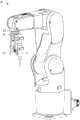
图2A为显示本发明实施例的机械手臂的示意图。FIG. 2A is a schematic diagram showing a robotic arm according to an embodiment of the present invention.
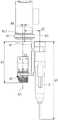
图2B、图2C为显示本发明实施例的机械手臂的细部结构。FIG. 2B and FIG. 2C show the detailed structure of the robot arm according to the embodiment of the present invention.
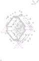
图3A为显示本发明实施例的校正装置的立体图。3A is a perspective view showing a calibration device according to an embodiment of the present invention.
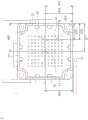
图3B为显示本发明实施例的校正装置的俯视图。FIG. 3B is a top view showing the calibration device according to the embodiment of the present invention.
图3C为显示本发明实施例的校正装置的爆炸图。FIG. 3C is an exploded view showing the calibration device according to the embodiment of the present invention.
图4为显示本发明一实施例的影像辨识图样。FIG. 4 shows an image recognition pattern according to an embodiment of the present invention.
图5为显示本发明一实施例的相对尺寸量测值。FIG. 5 is a diagram showing relative size measurements of an embodiment of the present invention.
图6为显示本发明另一实施例的相对尺寸量测值。FIG. 6 shows relative size measurements of another embodiment of the present invention.
其中附图标记为:The reference numerals are:
S11、S12、S13、S14、S15、S16~步骤S11, S12, S13, S14, S15, S16~steps
R~机械手臂R~Robot arm
T~加工工具T~Processing tool
C~校正装置C~calibration device
1~框体1~Frame
11~侧壁11~Sidewall
111~第一光栅孔111~The first grating hole
113~第三光栅孔113~The third grating hole
12~侧壁12~Sidewall
122~第二光栅孔122~Second grating hole
13~侧壁13~Sidewall
14~侧壁14~Sidewall
15~底板15~Bottom plate
2~影像辨识图案2~Image recognition pattern
31~第一量测点31~The first measurement point
32~第二量测点32~Second measuring point
33~第三量测点33~The third measurement point
341~第一轴线341~The first axis
342~第二轴线342~Second axis
411~第一发光单元411~The first light-emitting unit
412~第一接收单元412 ~ The first receiving unit
421~第二发光单元421~Second light-emitting unit
422~第二接收单元422~Second receiving unit
431~第三发光单元431~The third light-emitting unit
432~第三接收单元432 ~ The third receiving unit
51~第一光线51~First Ray
52~第二光线52~Second Ray
53~第三光线53~Third Ray
81~连结座81~Connector
811~末端基准点811~End reference point
82~影像捕获设备82~Image capture device
83~末端连杆83~End link
d1、d2、d3、d4、d5、d6~相对距离d1, d2, d3, d4, d5, d6~relative distance
d12、d13、d22、d23、d32、d33、dc2、dc3~距离d12, d13, d22, d23, d32, d33, dc2, dc3~distance
P1~光线交叉点P1~ray intersection
A1、A2~基准轴A1, A2~reference axis
具体实施方式Detailed ways
参照图1,其为显示本发明实施例的机械手臂工具校正方法的流程图。本发明的实施例的机械手臂工具校正方法,包括下述步骤。首先,提供一机械手臂,该机械手臂包括一末端基准点、一连接座以及一影像捕获设备(S11)。接着,提供一加工工具,该加工工具以及该影像捕获设备被安装于该连结座(S12)。再,提供一校正装置,该校正装置包括一影像辨识图样,其中,该校正装置更包括一第一量测点,一第二量测点以及一第三量测点(S13)。接着,以该影像捕获设备撷取该影像辨识图样以及该第一量测点、该第二量测点以及该第三量测点的影像,并依据该影像辨识图样计算取得该影像捕获设备相对该末端基准点的一第一转移矩阵,计算出该影像捕获设备相对该末端基准点的实际坐标(d1,d4,d6)(S14)。再,由该影像捕获设备撷取取得的该第一量测点,该第二量测点以及该第三量测点的影像的尺寸量测值,以及该第一量测点,该第二量测点及该第三量测点实际的尺寸量测值计算取得该第一量测点,该第二量测点以及该第三量测点相对该末端基准点的一第二转移矩阵(S15)。接着,该校正装置的一第一光线以及一第二光线形成一光线交叉点,由该第二转移矩阵可推算出该光线交叉点相对该末端基准点的坐标(S16)。最后,以该机械手臂将该加工工具置入该校正装置内,并依据该第一光线、第二光线以及该第三光线被该加工工具遮挡的信息,使该加工工具的一端部移动至该光线交叉点的位置,由该光线交叉点相对于该末端基准点的坐标为一基准坐标,计算出该加工工具的一端部相对于该末端基准点的实际坐标(d2,d3,d5),完成工具自动更正(S17)。Referring to FIG. 1 , it is a flowchart showing a method for calibrating a tool of a robotic arm according to an embodiment of the present invention. The method for calibrating a robot arm tool according to an embodiment of the present invention includes the following steps. First, a robotic arm is provided, the robotic arm includes an end reference point, a connecting seat and an image capturing device (S11). Next, a processing tool is provided, and the processing tool and the image capturing device are mounted on the connecting seat ( S12 ). Furthermore, a calibration device is provided, the calibration device includes an image recognition pattern, wherein the calibration device further includes a first measurement point, a second measurement point and a third measurement point (S13). Next, capture the image recognition pattern and the images of the first measurement point, the second measurement point and the third measurement point by the image capture device, and calculate and obtain the relative image of the image capture device according to the image recognition pattern. A first transition matrix of the end reference point, and the actual coordinates (d1, d4, d6) of the image capture device relative to the end reference point are calculated (S14). Then, the size measurement values of the images of the first measurement point, the second measurement point and the third measurement point captured by the image capture device, as well as the first measurement point, the second measurement point The actual size measurement values of the measurement point and the third measurement point are calculated to obtain a second transfer matrix ( S15). Next, a first ray and a second ray of the calibration device form a ray intersection, and the coordinates of the ray intersection relative to the end reference point can be calculated from the second transition matrix ( S16 ). Finally, the machining tool is placed in the calibration device by the robotic arm, and according to the information that the first light, the second light and the third light are blocked by the machining tool, one end of the machining tool is moved to the The position of the intersection of the light rays, the coordinates of the intersection of the light rays relative to the reference point of the end is a reference coordinate, and the actual coordinates (d2, d3, d5) of one end of the processing tool relative to the reference point of the end are calculated, and the completion The tool automatically corrects (S17).
图2A、图2B以及图2C为显示本发明实施例的机械手臂的示意图。图3A系显示本发明实施例的校正装置C的立体图。搭配参照第1、2A、2B以及2C、3A图,该机械手臂R包括一连接座81以及一影像捕获设备82,该连接座81包括一末端基准点811。该末端基准点811可以为该机械手臂R的手臂腕部上的适当位置,上述揭露并未限制本发明。2A , 2B and 2C are schematic diagrams illustrating a robotic arm according to an embodiment of the present invention. FIG. 3A is a perspective view showing a calibration device C according to an embodiment of the present invention. Referring to FIGS. 1 , 2A, 2B, and 2C and 3A, the robotic arm R includes a
依据该第一转移矩阵,可以计算取得该影像捕获设备82的镜头与末端基准点811之间的相对距离d1、该影像捕获设备82的基准轴A1与该末端基准点811之间的相对距离d4以及该影像捕获设备82的基准轴A1与该末端基准点811之间的相对距离d6。According to the first transition matrix, the relative distance d1 between the lens of the
由该光线交叉点相对于该末端基准点的坐标为一基准坐标,可计算出该加工工具的一端部相对于该末端基准点的实际坐标,包括该加工工具T的工具基准轴A2与该末端基准点811之间的相对距离d2、该加工工具的该端部与该末端基准点811之间的相对距离d3以及该影像捕获设备82的基准轴A1与该加工工具T的工具基准轴A2之间的相对距离d5。From the coordinates of the ray intersection relative to the end reference point as a reference coordinate, the actual coordinates of one end of the machining tool relative to the end reference point can be calculated, including the tool reference axis A2 of the machining tool T and the end The relative distance d2 between the
搭配参照图2A、图2B以及图2C、图3A,该加工工具T以及该影像捕获设备82被安装于该连结座81,该加工工具T可以为刀具、烙铁头或其他加工工具。2A, 2B and 2C, 3A, the processing tool T and the
参照图4,其为显示本发明一实施例的影像辨识图样2,该影像辨识图样2包括点、线以及方向指针等等特征。该影像辨识图样2可以适度变化,上述揭露并未限制本发明。Referring to FIG. 4 , it shows an
图3B为显示本发明实施例的校正装置C的俯视图。参照图第3B、4图,该校正装置C包括该第一量测点31、该第二量测点32以及该第三量测点33,该第一量测点31以及该第二量测点32沿该第一轴线341设置,该第二量测点32以及该第三量测点33沿该第二轴线342设置,该第二轴线342垂直于该第一轴线341。FIG. 3B is a top view showing the calibration device C according to the embodiment of the present invention. 3B, 4, the calibration device C includes the
图3C为显示本发明实施例的校正装置C的爆炸图。搭配参照图3C,在一实施例中,该校正装置更包括一第一光学感测装置、一第二光学感测装置以及一第三光学感测装。第一光学感测装置包括一第一发光单元411以及一第一接收单元412。第二光学感测装置包括一第二发光单元421以及一第二接收单元422。第三光学感测装置包括一第三发光单元431以及一第三接收单元432。该第一发光单元411提供一第一光线51,该第二发光单元421提供一第二光线52,该第三发光单元431提供一第三光线53,该第一光线51适于被该第一接收单元412所接收,该第二光线52适于被该第二接收单元422所接收,该第三光线53适于被该第三接收单元432所接收。FIG. 3C is an exploded view showing the calibration device C according to the embodiment of the present invention. Referring to FIG. 3C , in one embodiment, the calibration device further includes a first optical sensing device, a second optical sensing device and a third optical sensing device. The first optical sensing device includes a first light-emitting
在本发明的实施例中,由于框体一体成型制作,机械加工孔的基准与框体相同,通过本发明提出的三个机械加工孔产生的坐标系(第二转移矩阵),使视觉坐标系与光轴交点的物理坐标系产生连接,修正视觉产生的坐标系,使光轴交点的坐标亦可以转换为机械手坐标系。工具模块校正时,可以通过光轴交点的位置,系统可以自动建立机械手坐标系、视觉坐标系和工具坐标的关联,取代现有需要操作人员将工具尖端与尖点装置对准的步骤。In the embodiment of the present invention, since the frame body is integrally formed, the datum of the machining hole is the same as that of the frame body. The coordinate system (second transition matrix) generated by the three machining holes proposed in the present invention makes the visual coordinate system It is connected with the physical coordinate system of the intersection of the optical axis, and the coordinate system generated by vision is corrected, so that the coordinates of the intersection of the optical axis can also be converted into the coordinate system of the manipulator. When the tool module is calibrated, the system can automatically establish the relationship between the robot coordinate system, the visual coordinate system and the tool coordinate through the position of the intersection of the optical axis, replacing the existing steps that require the operator to align the tool tip with the cusp device.
在本发明的实施例中,可以准确的定义该校正装置的该第一光线51、该第二光线52以及该第三光线53与该末端基准点间的位置关系。在一实施例中,由于影像辨识图样2以二次加工,例如印刷的方式形成于该框体1,因此因为加工误差的原因,第一坐标与该第二坐标系之间存在偏差,需要该第二转移矩阵进行补偿。In the embodiment of the present invention, the positional relationship between the
该相对尺寸量测值通过预先量测该第一量测点31、该第二量测点32以及该第三量测点33相对该第一光线51、该第二光线52以及该第三光线53之间的位置关系而获得。在一实施例中,该相对尺寸量测值可以通过三次元量测设备获得。The relative size measurement value is measured relative to the
搭配参照图3A、图3B以及图3C,在一实施例中,该校正装置C包括一框体1以及一影像辨识图样2。该框体1包括一底板15、一侧壁11、一侧壁12、一侧壁13以及一侧壁14。该侧壁11垂直于该侧壁12,该侧壁11面向并平行于该侧壁13,该侧壁12面向并平行于该侧壁14。该侧壁11、该侧壁12、该侧壁13以及该侧壁14环设于该底板15的边缘。该影像辨识图样2设于该底板15。该底板15具有该第一量测点31、该第二量测点32以及该第三量测点33,该第一量测点31以及该第二量测点32沿该第一轴线341设置,该第二量测点32以及该第三量测点33沿该第二轴线342设置,该第二轴线342垂直于该第一轴线341。Referring to FIG. 3A , FIG. 3B and FIG. 3C together, in one embodiment, the calibration device C includes a
在一实施例中,该第一量测点31、该第二量测点32以及该第三量测点33可以为盲孔,其以预加工的方式形成于该底板15。该第一量测点31、该第二量测点32以及该第三量测点33亦可以为贯孔、凸点或其他特征。In one embodiment, the
参照图5,在一实施例中,该相对尺寸量测值包括该第一量测点31与该侧壁12之间的距离d12以及第一量测点31与该侧壁13之间的距离d13、第二量测点32与该侧壁12之间的距离d22以及第二量测点32与该侧壁13之间的距离d23、第三量测点33与该侧壁12之间的距离d32以及第三量测点33与该侧壁13之间的距离d33、底板15中心与该侧壁12之间的距离dc2以及底板15中心与该侧壁13之间的距离dc3等等数值。在上述实施例中,以侧壁当量测基准仅是实施例,任意基准皆可做为量测基准,只要能求出第一量测点31、第二量测点32与第三量测点33之间的相互尺寸即可以求出转移矩阵。5 , in one embodiment, the relative size measurement value includes the distance d12 between the
参照图6,在另一实施例中,第一量测点31、第二量测点32与第三量测点33的位置亦可以适度变化,只要能求出第一量测点31、第二量测点32与第三量测点33之间的相互尺寸即可以求出转移矩阵。Referring to FIG. 6 , in another embodiment, the positions of the
搭配参照图3A、图3B以及图3C,在一实施例中,该校正装置更包括该第一发光单元411、该第二发光单元421、该第三发光单元431、该第一接收单元412、该第二接收单元422以及该第三接收单元432,该第一发光单元411提供该第一光线51,该第二发光单元421提供该第二光线52,该第三发光单元431提供该第三光线53,该第一光线51适于被该第一接收单元412所接收,该第二光线52适于被该第二接收单元422所接收,该第三光线53适于被该第三接收单元432所接收,该第一光线51以及该第二光线52位于一第一平面之上,该第三光线53位于一第二平面之上,该第一平面平行于该第二平面,该第一平面不同于该第二平面,该第一平面与该影像辨识图样平行该第一光线51以及该第二光线52于一光线交叉点P1(图3A)交叉。3A, 3B and 3C, in one embodiment, the calibration device further includes the first light-emitting
搭配参照图3A、图3B以及图3C,在一实施例中,该光线交叉点P1与该第一量测点31的该第一圆心位于一直线之上,该直线垂直于该底板15。3A , FIG. 3B and FIG. 3C , in one embodiment, the light intersection point P1 and the first circle center of the
搭配参照图3A、图3B以及图3C,在一实施例中,该第一光线经过该第二量测点的一第二圆心的上方。Referring to FIG. 3A , FIG. 3B and FIG. 3C together, in one embodiment, the first light beam passes above a second center of the second measurement point.
搭配参照图3A、图3B以及图3C,在一实施例中,该第一发光单元411设于该侧壁11,该第二发光单元421设于该侧壁12,该第一接收单元412设于该侧壁13,该第二接收单元422设于该侧壁14。3A , 3B and 3C, in one embodiment, the first light-emitting
搭配参照图3A、图3B以及图3C,在一实施例中,该第三发光单元431设于该侧壁11,该第一发光单元411在一Z方向上位于该第三发光单元431与该底板15之间。3A, 3B and 3C, in one embodiment, the third light-emitting
搭配参照图3A、图3B以及图3C,在一实施例中,在一实施例中,该等侧壁于一第一高度分别设有一第一光栅孔61,一第二光栅孔62、一第三光栅孔63及一第四光栅孔64。该第一光栅孔61、该第二光栅孔62、该第三光栅孔63及该第四光栅孔64则呈两两平行相对。在一实施例中,一第五光栅孔65及一第六光栅孔66位于该侧壁的一第二高度,且该第五光珊孔65及该第六光栅孔66呈平行相对。该第二高度高于该第一高度。该第一发光单元411的该第一光线51穿透该第一光栅孔61经由该第二光栅孔62,由该第一接收单元412所接收。该第二发光单元421的该第二光线52穿透该第三光栅孔63经由该第四光栅孔64,由该第二接收单元422所接收。该第三发光单元431的该第三光线53穿透该第五光栅孔65经由该第六光栅孔66,由该第三接收单元432所接收。3A, 3B and 3C, in one embodiment, in one embodiment, the sidewalls are respectively provided with a first
在上述实施例中,该第一光线51以及该第二光线52位于该第一高度形成一第一平面,该第三光线53位于该第二高度形成一第二面,该第一平面平行于该第二平面,该第一平面与该影像辨识图样平行,该第一光线51以及该第二光线52形成一光线交叉点P1。In the above embodiment, the
在上述实施例中,各光栅孔为微小而准直的开孔,可准直该第一光线51、该第二光线52以及该第三光线53。In the above-mentioned embodiment, each grating hole is a small and collimated opening, which can collimate the
在一实施例中,该等侧壁可以彼此垂直。然而,上述揭露并未限制本发明。在另一实施例中,该等侧壁亦可以为连续侧壁,例如圆形侧壁。In one embodiment, the side walls may be perpendicular to each other. However, the above disclosure does not limit the present invention. In another embodiment, the side walls can also be continuous side walls, such as circular side walls.
虽然本发明已以具体的较佳实施例揭露如上,然其并非用以限定本发明,任何熟习此项技术者,在不脱离本发明的精神和范围内,仍可作些许的更动与润饰,因此本发明的保护范围当视后附的权利要求所界定者为准。Although the present invention has been disclosed above with specific preferred embodiments, it is not intended to limit the present invention. Anyone skilled in the art can still make some changes and modifications without departing from the spirit and scope of the present invention. Therefore, the protection scope of the present invention should be determined by the appended claims.
Claims (14)
Priority Applications (3)
| Application Number | Priority Date | Filing Date | Title |
|---|---|---|---|
| CN201910212670.2ACN111716346B (en) | 2019-03-20 | 2019-03-20 | Method and device for correcting tool of mechanical arm |
| EP19195728.1AEP3711908B1 (en) | 2019-03-20 | 2019-09-05 | Calibration device for robot arm |
| US16/571,492US11260532B2 (en) | 2019-03-20 | 2019-09-16 | Calibration method for robot arm and calibration device thereof |
Applications Claiming Priority (1)
| Application Number | Priority Date | Filing Date | Title |
|---|---|---|---|
| CN201910212670.2ACN111716346B (en) | 2019-03-20 | 2019-03-20 | Method and device for correcting tool of mechanical arm |
Publications (2)
| Publication Number | Publication Date |
|---|---|
| CN111716346Atrue CN111716346A (en) | 2020-09-29 |
| CN111716346B CN111716346B (en) | 2021-09-17 |
Family
ID=67874396
Family Applications (1)
| Application Number | Title | Priority Date | Filing Date |
|---|---|---|---|
| CN201910212670.2AActiveCN111716346B (en) | 2019-03-20 | 2019-03-20 | Method and device for correcting tool of mechanical arm |
Country Status (3)
| Country | Link |
|---|---|
| US (1) | US11260532B2 (en) |
| EP (1) | EP3711908B1 (en) |
| CN (1) | CN111716346B (en) |
Cited By (1)
| Publication number | Priority date | Publication date | Assignee | Title |
|---|---|---|---|---|
| CN117656048A (en)* | 2022-09-08 | 2024-03-08 | 无锡芯享信息科技有限公司 | AGV grabbing point calibration equipment and calibration method thereof |
Families Citing this family (4)
| Publication number | Priority date | Publication date | Assignee | Title |
|---|---|---|---|---|
| US11059178B2 (en)* | 2018-12-27 | 2021-07-13 | Kawasaki Jukogyo Kabushiki Kaisha | Method of correcting position of robot and robot |
| CN114310868B (en)* | 2020-09-29 | 2023-08-01 | 台达电子工业股份有限公司 | Coordinate system correction device and method for robot arm |
| CN112549077B (en)* | 2020-12-03 | 2022-02-01 | 重庆工程职业技术学院 | A kinematics analytical equipment for parallelly connected manipulator |
| CN113442133B (en)* | 2021-06-09 | 2024-09-10 | 配天机器人技术有限公司 | Tool center point calibration method and system for robot and storage medium |
Citations (19)
| Publication number | Priority date | Publication date | Assignee | Title |
|---|---|---|---|---|
| EP1875991A2 (en)* | 2006-07-03 | 2008-01-09 | Fanuc Ltd | Measuring system and calibration method |
| US20090157226A1 (en)* | 2004-11-19 | 2009-06-18 | Dynalog ,Inc. | Robot-cell calibration |
| US20110029131A1 (en)* | 2009-08-03 | 2011-02-03 | Fanuc Ltd | Apparatus and method for measuring tool center point position of robot |
| US20110320039A1 (en)* | 2010-06-25 | 2011-12-29 | Hon Hai Precision Industry Co., Ltd. | Robot calibration system and calibrating method thereof |
| US8180487B1 (en)* | 2008-09-30 | 2012-05-15 | Western Digital Technologies, Inc. | Calibrated vision based robotic system |
| CN103009392A (en)* | 2011-09-21 | 2013-04-03 | 鸿富锦精密工业(深圳)有限公司 | System and method for correcting coordinate of mechanical arm |
| WO2016079967A1 (en)* | 2014-11-21 | 2016-05-26 | Seiko Epson Corporation | Robot and robot system |
| CN105945948A (en)* | 2016-05-25 | 2016-09-21 | 南京工程学院 | TCP online quick calibration method and device applied to industrial robot |
| US20160368147A1 (en)* | 2014-04-30 | 2016-12-22 | Abb Schweiz Ag | Method for calibrating tool centre point for industrial robot system |
| TW201702034A (en)* | 2015-07-14 | 2017-01-16 | 財團法人工業技術研究院 | Calibration and monitoring equipment of mechanical system |
| US20170151671A1 (en)* | 2015-12-01 | 2017-06-01 | Seiko Epson Corporation | Control device, robot, and robot system |
| CN206937361U (en)* | 2017-04-11 | 2018-01-30 | 勃肯特(北京)机器人技术有限公司 | Robot zero point correction device and robot calibration system |
| CN108098799A (en)* | 2016-11-25 | 2018-06-01 | 株式会社东芝 | Robert controller, robot control method and pick device |
| US20180222056A1 (en)* | 2017-02-09 | 2018-08-09 | Canon Kabushiki Kaisha | Method of teaching robot and robot system |
| CN108946101A (en)* | 2017-05-24 | 2018-12-07 | 台达电子工业股份有限公司 | Conveying equipment |
| CN109015632A (en)* | 2018-07-11 | 2018-12-18 | 云南电网有限责任公司电力科学研究院 | A kind of robot hand end localization method |
| TWI648135B (en)* | 2018-06-19 | 2019-01-21 | 台達電子工業股份有限公司 | Tool calibration apparatus of robot manipulator |
| CN109434839A (en)* | 2018-12-25 | 2019-03-08 | 江南大学 | A kind of robot self-calibrating method based on monocular vision auxiliary positioning |
| CN109454634A (en)* | 2018-09-20 | 2019-03-12 | 广东工业大学 | A kind of Robotic Hand-Eye Calibration method based on flat image identification |
Family Cites Families (5)
| Publication number | Priority date | Publication date | Assignee | Title |
|---|---|---|---|---|
| CN107111250B (en)* | 2014-11-26 | 2019-10-11 | Asml荷兰有限公司 | Measurement methods, computer products and systems |
| EP3454124A1 (en)* | 2017-09-07 | 2019-03-13 | ASML Netherlands B.V. | Method to determine a patterning process parameter |
| IL273836B2 (en)* | 2017-10-31 | 2023-09-01 | Asml Netherlands Bv | Metrology apparatus, method of measuring a structure, device manufacturing method |
| IL310215A (en)* | 2018-06-13 | 2024-03-01 | Asml Netherlands Bv | Metrology apparatus |
| EP3647871A1 (en)* | 2018-10-31 | 2020-05-06 | ASML Netherlands B.V. | Method of determing a value of a parameter of interest of a patterning process, device manufacturing method |
- 2019
- 2019-03-20CNCN201910212670.2Apatent/CN111716346B/enactiveActive
- 2019-09-05EPEP19195728.1Apatent/EP3711908B1/enactiveActive
- 2019-09-16USUS16/571,492patent/US11260532B2/enactiveActive
Patent Citations (19)
| Publication number | Priority date | Publication date | Assignee | Title |
|---|---|---|---|---|
| US20090157226A1 (en)* | 2004-11-19 | 2009-06-18 | Dynalog ,Inc. | Robot-cell calibration |
| EP1875991A2 (en)* | 2006-07-03 | 2008-01-09 | Fanuc Ltd | Measuring system and calibration method |
| US8180487B1 (en)* | 2008-09-30 | 2012-05-15 | Western Digital Technologies, Inc. | Calibrated vision based robotic system |
| US20110029131A1 (en)* | 2009-08-03 | 2011-02-03 | Fanuc Ltd | Apparatus and method for measuring tool center point position of robot |
| US20110320039A1 (en)* | 2010-06-25 | 2011-12-29 | Hon Hai Precision Industry Co., Ltd. | Robot calibration system and calibrating method thereof |
| CN103009392A (en)* | 2011-09-21 | 2013-04-03 | 鸿富锦精密工业(深圳)有限公司 | System and method for correcting coordinate of mechanical arm |
| US20160368147A1 (en)* | 2014-04-30 | 2016-12-22 | Abb Schweiz Ag | Method for calibrating tool centre point for industrial robot system |
| WO2016079967A1 (en)* | 2014-11-21 | 2016-05-26 | Seiko Epson Corporation | Robot and robot system |
| TW201702034A (en)* | 2015-07-14 | 2017-01-16 | 財團法人工業技術研究院 | Calibration and monitoring equipment of mechanical system |
| US20170151671A1 (en)* | 2015-12-01 | 2017-06-01 | Seiko Epson Corporation | Control device, robot, and robot system |
| CN105945948A (en)* | 2016-05-25 | 2016-09-21 | 南京工程学院 | TCP online quick calibration method and device applied to industrial robot |
| CN108098799A (en)* | 2016-11-25 | 2018-06-01 | 株式会社东芝 | Robert controller, robot control method and pick device |
| US20180222056A1 (en)* | 2017-02-09 | 2018-08-09 | Canon Kabushiki Kaisha | Method of teaching robot and robot system |
| CN206937361U (en)* | 2017-04-11 | 2018-01-30 | 勃肯特(北京)机器人技术有限公司 | Robot zero point correction device and robot calibration system |
| CN108946101A (en)* | 2017-05-24 | 2018-12-07 | 台达电子工业股份有限公司 | Conveying equipment |
| TWI648135B (en)* | 2018-06-19 | 2019-01-21 | 台達電子工業股份有限公司 | Tool calibration apparatus of robot manipulator |
| CN109015632A (en)* | 2018-07-11 | 2018-12-18 | 云南电网有限责任公司电力科学研究院 | A kind of robot hand end localization method |
| CN109454634A (en)* | 2018-09-20 | 2019-03-12 | 广东工业大学 | A kind of Robotic Hand-Eye Calibration method based on flat image identification |
| CN109434839A (en)* | 2018-12-25 | 2019-03-08 | 江南大学 | A kind of robot self-calibrating method based on monocular vision auxiliary positioning |
Cited By (2)
| Publication number | Priority date | Publication date | Assignee | Title |
|---|---|---|---|---|
| CN117656048A (en)* | 2022-09-08 | 2024-03-08 | 无锡芯享信息科技有限公司 | AGV grabbing point calibration equipment and calibration method thereof |
| CN117656048B (en)* | 2022-09-08 | 2024-05-24 | 无锡芯享信息科技有限公司 | AGV grabbing point calibration equipment and calibration method thereof |
Also Published As
| Publication number | Publication date |
|---|---|
| US11260532B2 (en) | 2022-03-01 |
| EP3711908B1 (en) | 2023-04-19 |
| EP3711908A1 (en) | 2020-09-23 |
| CN111716346B (en) | 2021-09-17 |
| US20200298409A1 (en) | 2020-09-24 |
Similar Documents
| Publication | Publication Date | Title |
|---|---|---|
| CN111716346A (en) | Mechanical arm tool calibration method and its calibration device | |
| US20210291376A1 (en) | System and method for three-dimensional calibration of a vision system | |
| US7746481B2 (en) | Method for measuring center of rotation of a nozzle of a pick and place machine using a collimated laser beam | |
| JP6280525B2 (en) | System and method for runtime determination of camera miscalibration | |
| JP6025386B2 (en) | Image measuring apparatus, image measuring method, and image measuring program | |
| CN107462881A (en) | A kind of laser range sensor scaling method | |
| US20140100694A1 (en) | System and method for camera-based auto-alignment | |
| IL278170B1 (en) | Wireless substrate-like teaching sensor for semiconductor processing | |
| CN102294695A (en) | Robot calibration method and calibration system | |
| CN106355614A (en) | Mechanical system correcting and monitoring device | |
| CN110815201A (en) | Method for correcting coordinates of robot arm | |
| TWI696536B (en) | Calibration method for robot arm and calibration device thereof | |
| US11723183B2 (en) | Electronic component evaluation method, electronic component evaluation device, and electronic component evaluation program | |
| KR100238269B1 (en) | Coplanarity measurment apparatus for IC package lead fin | |
| US7355386B2 (en) | Method of automatically carrying IC-chips, on a planar array of vacuum nozzles, to a variable target in a chip tester | |
| CN115345943B (en) | Calibration method based on differential mode concept | |
| KR102627640B1 (en) | Teaching system of robot assembly provided in vacuum chamber | |
| JP2008260599A (en) | Method for adjusting transfer surface of semiconductor wafer transfer system, semiconductor wafer transfer system using the same, and semiconductor manufacturing apparatus | |
| JP2024086351A (en) | Origin calibration method and origin calibration system | |
| CN114571199A (en) | Screw locking machine and screw positioning method | |
| TWI860784B (en) | Method and system for calibrating a tool on a robotic arm and two-class method for calibrating a tool on a robotic arm | |
| US20240198534A1 (en) | Robot inspection system | |
| KR20110135666A (en) | Calibration device between robot and displacement sensor and calibration method using the same | |
| KR20240076864A (en) | Monitoring system of robot assembly provided in vacuum chamber | |
| CN115574769A (en) | Automatic target pose detection system |
Legal Events
| Date | Code | Title | Description |
|---|---|---|---|
| PB01 | Publication | ||
| PB01 | Publication | ||
| SE01 | Entry into force of request for substantive examination | ||
| SE01 | Entry into force of request for substantive examination | ||
| GR01 | Patent grant | ||
| GR01 | Patent grant |