CN111712211A - Robotic Stereotactic System for MRI-Guided Neurosurgery - Google Patents
Robotic Stereotactic System for MRI-Guided NeurosurgeryDownload PDFInfo
- Publication number
- CN111712211A CN111712211ACN201980010511.2ACN201980010511ACN111712211ACN 111712211 ACN111712211 ACN 111712211ACN 201980010511 ACN201980010511 ACN 201980010511ACN 111712211 ACN111712211 ACN 111712211A
- Authority
- CN
- China
- Prior art keywords
- needle
- surgical robot
- rack
- pinion
- actuator
- Prior art date
- Legal status (The legal status is an assumption and is not a legal conclusion. Google has not performed a legal analysis and makes no representation as to the accuracy of the status listed.)
- Granted
Links
- 210000000988bone and boneAnatomy0.000claimsabstractdescription8
- 238000002595magnetic resonance imagingMethods0.000claimsdescription30
- 210000002435tendonAnatomy0.000claimsdescription25
- 210000000245forearmAnatomy0.000claimsdescription23
- 210000003625skullAnatomy0.000claimsdescription21
- 239000012530fluidSubstances0.000claimsdescription18
- 238000005096rolling processMethods0.000claimsdescription9
- 230000005291magnetic effectEffects0.000claimsdescription6
- 210000004556brainAnatomy0.000abstractdescription19
- 230000002146bilateral effectEffects0.000abstractdescription14
- 238000002672stereotactic surgeryMethods0.000abstractdescription2
- 238000003745diagnosisMethods0.000abstract1
- 238000000034methodMethods0.000description15
- 238000003780insertionMethods0.000description12
- 230000037431insertionEffects0.000description12
- 230000005540biological transmissionEffects0.000description11
- 238000001356surgical procedureMethods0.000description10
- 238000012360testing methodMethods0.000description10
- 238000010586diagramMethods0.000description9
- 238000003384imaging methodMethods0.000description8
- 230000033001locomotionEffects0.000description8
- 238000013461designMethods0.000description7
- 239000010410layerSubstances0.000description7
- 230000015654memoryEffects0.000description7
- 238000002591computed tomographyMethods0.000description5
- 238000006073displacement reactionMethods0.000description5
- 230000007246mechanismEffects0.000description5
- 230000002980postoperative effectEffects0.000description5
- 230000036316preloadEffects0.000description5
- 230000008569processEffects0.000description5
- 230000000638stimulationEffects0.000description5
- 208000018737Parkinson diseaseDiseases0.000description4
- 210000004281subthalamic nucleusAnatomy0.000description4
- 239000007779soft materialSubstances0.000description3
- 230000003068static effectEffects0.000description3
- 230000008685targetingEffects0.000description3
- 238000011282treatmentMethods0.000description3
- 208000014094Dystonic diseaseDiseases0.000description2
- FNYLWPVRPXGIIP-UHFFFAOYSA-NTriamtereneChemical compoundNC1=NC2=NC(N)=NC(N)=C2N=C1C1=CC=CC=C1FNYLWPVRPXGIIP-UHFFFAOYSA-N0.000description2
- 238000004873anchoringMethods0.000description2
- 210000001175cerebrospinal fluidAnatomy0.000description2
- 230000008859changeEffects0.000description2
- 230000006378damageEffects0.000description2
- 239000002355dual-layerSubstances0.000description2
- 208000010118dystoniaDiseases0.000description2
- 239000012636effectorSubstances0.000description2
- 230000004807localizationEffects0.000description2
- 239000003550markerSubstances0.000description2
- 239000000463materialSubstances0.000description2
- 238000012986modificationMethods0.000description2
- 230000004048modificationEffects0.000description2
- 230000009467reductionEffects0.000description2
- 230000004044responseEffects0.000description2
- 238000000264spin echo pulse sequenceMethods0.000description2
- XLYOFNOQVPJJNP-UHFFFAOYSA-NwaterSubstancesOXLYOFNOQVPJJNP-UHFFFAOYSA-N0.000description2
- 2380000101463D printingMethods0.000description1
- 229920001817AgarPolymers0.000description1
- 229920000936AgarosePolymers0.000description1
- 208000024827Alzheimer diseaseDiseases0.000description1
- 206010002091AnaesthesiaDiseases0.000description1
- 208000019901Anxiety diseaseDiseases0.000description1
- 229920000049Carbon (fiber)Polymers0.000description1
- 208000016285Movement diseaseDiseases0.000description1
- 239000004809TeflonSubstances0.000description1
- 229920006362Teflon®Polymers0.000description1
- 208000027418Wounds and injuryDiseases0.000description1
- 230000037005anaesthesiaEffects0.000description1
- 230000036506anxietyEffects0.000description1
- 230000002457bidirectional effectEffects0.000description1
- 238000009534blood testMethods0.000description1
- 210000005013brain tissueAnatomy0.000description1
- 239000004917carbon fiberSubstances0.000description1
- 210000004027cellAnatomy0.000description1
- 238000004891communicationMethods0.000description1
- 238000007796conventional methodMethods0.000description1
- 238000007428craniotomyMethods0.000description1
- 230000000593degrading effectEffects0.000description1
- 238000011161developmentMethods0.000description1
- 201000010099diseaseDiseases0.000description1
- 208000037265diseases, disorders, signs and symptomsDiseases0.000description1
- 239000012153distilled waterSubstances0.000description1
- 230000005611electricityEffects0.000description1
- 206010015037epilepsyDiseases0.000description1
- 230000005284excitationEffects0.000description1
- 239000004744fabricSubstances0.000description1
- 230000005294ferromagnetic effectEffects0.000description1
- 238000002594fluoroscopyMethods0.000description1
- 210000001905globus pallidusAnatomy0.000description1
- 230000005484gravityEffects0.000description1
- ACGUYXCXAPNIKK-UHFFFAOYSA-NhexachloropheneChemical compoundOC1=C(Cl)C=C(Cl)C(Cl)=C1CC1=C(O)C(Cl)=CC(Cl)=C1ClACGUYXCXAPNIKK-UHFFFAOYSA-N0.000description1
- 208000014674injuryDiseases0.000description1
- 238000007917intracranial administrationMethods0.000description1
- 239000007788liquidSubstances0.000description1
- 238000005461lubricationMethods0.000description1
- 239000011159matrix materialSubstances0.000description1
- 238000005259measurementMethods0.000description1
- 239000012528membraneSubstances0.000description1
- VNWKTOKETHGBQD-UHFFFAOYSA-NmethaneChemical compoundCVNWKTOKETHGBQD-UHFFFAOYSA-N0.000description1
- 238000012544monitoring processMethods0.000description1
- 210000000653nervous systemAnatomy0.000description1
- 230000001537neural effectEffects0.000description1
- 230000003287optical effectEffects0.000description1
- 239000004033plasticSubstances0.000description1
- 229920000642polymerPolymers0.000description1
- 230000000644propagated effectEffects0.000description1
- 208000020016psychiatric diseaseDiseases0.000description1
- 230000005855radiationEffects0.000description1
- 239000000700radioactive tracerSubstances0.000description1
- 230000035945sensitivityEffects0.000description1
- 230000004936stimulating effectEffects0.000description1
- 208000024891symptomDiseases0.000description1
- 238000002560therapeutic procedureMethods0.000description1
- 238000012546transferMethods0.000description1
Images


Classifications
- A—HUMAN NECESSITIES
- A61—MEDICAL OR VETERINARY SCIENCE; HYGIENE
- A61B—DIAGNOSIS; SURGERY; IDENTIFICATION
- A61B34/00—Computer-aided surgery; Manipulators or robots specially adapted for use in surgery
- A61B34/20—Surgical navigation systems; Devices for tracking or guiding surgical instruments, e.g. for frameless stereotaxis
- A—HUMAN NECESSITIES
- A61—MEDICAL OR VETERINARY SCIENCE; HYGIENE
- A61B—DIAGNOSIS; SURGERY; IDENTIFICATION
- A61B34/00—Computer-aided surgery; Manipulators or robots specially adapted for use in surgery
- A61B34/70—Manipulators specially adapted for use in surgery
- A61B34/71—Manipulators operated by drive cable mechanisms
- A—HUMAN NECESSITIES
- A61—MEDICAL OR VETERINARY SCIENCE; HYGIENE
- A61B—DIAGNOSIS; SURGERY; IDENTIFICATION
- A61B34/00—Computer-aided surgery; Manipulators or robots specially adapted for use in surgery
- A61B34/30—Surgical robots
- A—HUMAN NECESSITIES
- A61—MEDICAL OR VETERINARY SCIENCE; HYGIENE
- A61B—DIAGNOSIS; SURGERY; IDENTIFICATION
- A61B34/00—Computer-aided surgery; Manipulators or robots specially adapted for use in surgery
- A61B34/30—Surgical robots
- A61B34/35—Surgical robots for telesurgery
- A—HUMAN NECESSITIES
- A61—MEDICAL OR VETERINARY SCIENCE; HYGIENE
- A61B—DIAGNOSIS; SURGERY; IDENTIFICATION
- A61B34/00—Computer-aided surgery; Manipulators or robots specially adapted for use in surgery
- A61B34/30—Surgical robots
- A61B34/37—Leader-follower robots
- A—HUMAN NECESSITIES
- A61—MEDICAL OR VETERINARY SCIENCE; HYGIENE
- A61B—DIAGNOSIS; SURGERY; IDENTIFICATION
- A61B90/00—Instruments, implements or accessories specially adapted for surgery or diagnosis and not covered by any of the groups A61B1/00 - A61B50/00, e.g. for luxation treatment or for protecting wound edges
- A61B90/10—Instruments, implements or accessories specially adapted for surgery or diagnosis and not covered by any of the groups A61B1/00 - A61B50/00, e.g. for luxation treatment or for protecting wound edges for stereotaxic surgery, e.g. frame-based stereotaxis
- A61B90/11—Instruments, implements or accessories specially adapted for surgery or diagnosis and not covered by any of the groups A61B1/00 - A61B50/00, e.g. for luxation treatment or for protecting wound edges for stereotaxic surgery, e.g. frame-based stereotaxis with guides for needles or instruments, e.g. arcuate slides or ball joints
- A—HUMAN NECESSITIES
- A61—MEDICAL OR VETERINARY SCIENCE; HYGIENE
- A61B—DIAGNOSIS; SURGERY; IDENTIFICATION
- A61B90/00—Instruments, implements or accessories specially adapted for surgery or diagnosis and not covered by any of the groups A61B1/00 - A61B50/00, e.g. for luxation treatment or for protecting wound edges
- A61B90/36—Image-producing devices or illumination devices not otherwise provided for
- A61B90/37—Surgical systems with images on a monitor during operation
- G—PHYSICS
- G01—MEASURING; TESTING
- G01R—MEASURING ELECTRIC VARIABLES; MEASURING MAGNETIC VARIABLES
- G01R33/00—Arrangements or instruments for measuring magnetic variables
- G01R33/20—Arrangements or instruments for measuring magnetic variables involving magnetic resonance
- G01R33/28—Details of apparatus provided for in groups G01R33/44 - G01R33/64
- G01R33/285—Invasive instruments, e.g. catheters or biopsy needles, specially adapted for tracking, guiding or visualization by NMR
- G01R33/287—Invasive instruments, e.g. catheters or biopsy needles, specially adapted for tracking, guiding or visualization by NMR involving active visualization of interventional instruments, e.g. using active tracking RF coils or coils for intentionally creating magnetic field inhomogeneities
- A—HUMAN NECESSITIES
- A61—MEDICAL OR VETERINARY SCIENCE; HYGIENE
- A61B—DIAGNOSIS; SURGERY; IDENTIFICATION
- A61B34/00—Computer-aided surgery; Manipulators or robots specially adapted for use in surgery
- A61B34/20—Surgical navigation systems; Devices for tracking or guiding surgical instruments, e.g. for frameless stereotaxis
- A61B2034/2046—Tracking techniques
- A61B2034/2051—Electromagnetic tracking systems
- A—HUMAN NECESSITIES
- A61—MEDICAL OR VETERINARY SCIENCE; HYGIENE
- A61B—DIAGNOSIS; SURGERY; IDENTIFICATION
- A61B90/00—Instruments, implements or accessories specially adapted for surgery or diagnosis and not covered by any of the groups A61B1/00 - A61B50/00, e.g. for luxation treatment or for protecting wound edges
- A61B90/10—Instruments, implements or accessories specially adapted for surgery or diagnosis and not covered by any of the groups A61B1/00 - A61B50/00, e.g. for luxation treatment or for protecting wound edges for stereotaxic surgery, e.g. frame-based stereotaxis
- A61B2090/103—Cranial plugs for access to brain
- A—HUMAN NECESSITIES
- A61—MEDICAL OR VETERINARY SCIENCE; HYGIENE
- A61B—DIAGNOSIS; SURGERY; IDENTIFICATION
- A61B90/00—Instruments, implements or accessories specially adapted for surgery or diagnosis and not covered by any of the groups A61B1/00 - A61B50/00, e.g. for luxation treatment or for protecting wound edges
- A61B90/36—Image-producing devices or illumination devices not otherwise provided for
- A61B90/37—Surgical systems with images on a monitor during operation
- A61B2090/374—NMR or MRI
Landscapes
- Health & Medical Sciences (AREA)
- Surgery (AREA)
- Life Sciences & Earth Sciences (AREA)
- Engineering & Computer Science (AREA)
- General Health & Medical Sciences (AREA)
- Nuclear Medicine, Radiotherapy & Molecular Imaging (AREA)
- Animal Behavior & Ethology (AREA)
- Veterinary Medicine (AREA)
- Medical Informatics (AREA)
- Molecular Biology (AREA)
- Biomedical Technology (AREA)
- Heart & Thoracic Surgery (AREA)
- Public Health (AREA)
- Robotics (AREA)
- Pathology (AREA)
- Oral & Maxillofacial Surgery (AREA)
- Physics & Mathematics (AREA)
- Condensed Matter Physics & Semiconductors (AREA)
- General Physics & Mathematics (AREA)
- Gynecology & Obstetrics (AREA)
- Radiology & Medical Imaging (AREA)
- Magnetic Resonance Imaging Apparatus (AREA)
Abstract
Description
Translated fromChinese技术领域technical field
本发明的实施例涉及医疗机器人,特别涉及用于磁共振成像(MRI)引导的干预的手术机器人。Embodiments of the present invention relate to medical robots, and in particular to surgical robots for magnetic resonance imaging (MRI) guided interventions.
背景技术Background technique
立体定向术是一种可以使用外部坐标系作为参考来定位手术目标的技术。它在功能性神经外科手术中的应用主要旨在治疗各种运动障碍(例如帕金森氏病(PD)和肌张力障碍)、精神异常和癫痫。仅PD本身是神经系统中仅次于阿尔茨海默氏病的第二大疾病,预计到2030年将影响全球870万人。Stereotactic surgery is a technique that can use an external coordinate system as a reference to locate the surgical target. Its use in functional neurosurgery is primarily aimed at the treatment of various movement disorders (eg Parkinson's disease (PD) and dystonia), mental disorders and epilepsy. PD alone is the second most common disease of the nervous system after Alzheimer's disease, and is expected to affect 8.7 million people worldwide by 2030.
脑深部刺激术(DBS)是一种常见的立体定向手术,它是一种可减轻PD和肌张力障碍的运动症状的手术疗法。两个长的(例如300mm)细的

尽管立体定向神经外科手术的标准工作流程已经建立了半个多世纪,但由于其复杂的工作流程和对手术准确性的高要求,操作仍然具有挑战性。2-3mm的平均记录误差几乎无法容忍。在开颅手术后不可避免地发生的颅内内容物的大量变形,即“脑移位”,使立体定向导航进一步复杂化。这种移位主要是由于重力、脑脊液(CSF)泄漏、麻醉和手术操纵引起的。它可能会导致术前(pre-op)计划路径的失准(最大10-30mm),超出实际目标。与荧光透视/CT不同,MRI可以直接可视化关键的大脑结构和关注的目标(例如丘脑下核(STN)、内苍白球(GPi)或腹中间核)。Although the standard workflow for stereotactic neurosurgery has been established for more than half a century, the operation remains challenging due to its complex workflow and high demands on surgical accuracy. The average recording error of 2-3mm is almost intolerable. Stereotactic navigation is further complicated by the massive deformation of intracranial contents that inevitably occurs after craniotomy, known as "brain shift". This displacement is mainly caused by gravity, cerebrospinal fluid (CSF) leakage, anesthesia, and surgical manipulation. It may lead to misalignment of the pre-op planned path (up to 10-30mm) beyond the actual target. Unlike fluoroscopy/CT, MRI can directly visualize key brain structures and targets of interest (eg, subthalamic nucleus (STN), globus pallidus internal (GPi), or ventromedial nucleus).
目前,磁共振(MR)安全立体定向系统的选择非常有限(例如,爱尔兰美敦力公司的

紧凑性和MRI兼容性是关于常规医院设置中机器人的可行性和适应性的两个关键问题。很少有机器人平台可以装配在MRI头部线圈内,并且在连续成像期间也可以操作而不会降低图像质量。通常,没有用于功能性神经外科手术的机器人系统,其集成了MR安全致动和基于MR的追踪,能够在MRI孔内执行立体定向操纵。Compactness and MRI compatibility are two key issues regarding the feasibility and adaptability of robots in routine hospital settings. Few robotic platforms can fit inside an MRI head coil and also operate during continuous imaging without degrading image quality. Generally, there are no robotic systems for functional neurosurgery that integrate MR-safe actuation and MR-based tracking capable of performing stereotaxic manipulation within the MRI bore.
发明内容SUMMARY OF THE INVENTION
本发明的实施例提供了一种用于双侧立体定向手术的术中MRI引导的机器人。立体定向手术的安全性和有效性取决于两个主要因素:(1)在不损坏关键脑组织的情况下,细致地监控电极插入路径;以及(2)以高精度(<2mm)到达STN的能力。机器人设计为:i)紧凑,使得可以在头部线圈给出的严格尺寸限制内将机器人主体正确地固定在患者的颅骨上;ii)能够自动进行轨迹规划和仪器对准;iii)独立地进行双侧操纵;以及iv)通过确保机器人平台中不包含任何磁性部件,来满足MRI与ASTM F2503标准的兼容性。通常,机器人的操作不会在成像感兴趣区域(ROI)内引起明显的图像伪影或信噪比(SNR)的显著降低。Embodiments of the present invention provide an intraoperative MRI-guided robot for bilateral stereotaxic surgery. The safety and efficacy of stereotaxic surgery depend on two main factors: (1) careful monitoring of the electrode insertion path without damaging critical brain tissue; and (2) high accuracy (<2mm) to reach the STN. ability. The robot is designed to: i) be compact so that the robot body can be properly secured to the patient's skull within the strict size constraints given by the head coil; ii) be able to automate trajectory planning and instrument alignment; iii) independently Bilateral manipulation; and iv) MRI compliance with the ASTM F2503 standard by ensuring that no magnetic components are included in the robotic platform. Typically, manipulation of the robot does not cause significant image artifacts or significant reduction in signal-to-noise ratio (SNR) within the imaging region of interest (ROI).
本发明的实施例提供了紧凑的设计,其使得机器人能够在标准成像头部线圈的受限空间内双侧地操作。集成了MR安全、高性能的液压传动,其中可预加载工作介质并确保高传动刚度。在模拟的脑深部刺激术(DBS)的针插入任务中已经证明了足够的瞄准准确性。采用了基于MR的追踪技术,并能够在适当的MR追踪序列下提供机器人仪器的实时和连续(30-40Hz)三维定位。该技术优于使用只能在MR图像域中显示的低对比度被动基准点的常规方法。可以利用可以与机器人集成的无线追踪单元/标记,且其包括在柔性薄膜上制成的小型线圈电路。为了可视化机器人仪器的三维定位,已在标准MRI设定下执行了导航测试。MRI兼容性测试已证明对所提出的液压机器人平台的MR图像影响最小。Embodiments of the present invention provide a compact design that enables the robot to operate bilaterally within the confined space of a standard imaging head coil. The MR safe, high-performance hydraulic transmission is integrated, which preloads the working medium and ensures high transmission rigidity. Sufficient aiming accuracy has been demonstrated in a simulated deep brain stimulation (DBS) needle insertion task. MR-based tracking techniques are employed and are able to provide real-time and continuous (30-40Hz) 3D localization of robotic instruments under appropriate MR tracking sequences. This technique is superior to conventional methods using low-contrast passive fiducials that can only be visualized in the MR image domain. A wireless tracking unit/marker that can be integrated with the robot and includes a small coil circuit fabricated on a flexible film is available. To visualize the three-dimensional localization of the robotic instrument, navigation tests have been performed under standard MRI settings. MRI compatibility tests have demonstrated minimal impact on the MR images of the proposed hydraulic robotic platform.
本发明的实施例包括能够基于患者颅骨上的单个锚定来执行双侧神经立体定向术的第一术中MRI引导的机器人的以下开发。两个双侧目标的导航可以独立执行,也可以同时执行。轻巧紧凑的机器人设计成在MR成像头部线圈的受限的工作空间内操作。可以通过一组高性能的液压传动来致动机器人,这些液压传动具有MR安全性/产生最少的成像伪影。可以集成MRI引导的导航,并利用无线的基于MR的追踪线圈单元,以直接在MR图像坐标中提供实时位置反馈。这避免了追踪和成像空间的坐标之间的离线配准的任何过程。Embodiments of the present invention include the following development of a first intraoperative MRI-guided robot capable of performing bilateral neural stereotaxy based on a single anchor on the patient's skull. Navigation of the two bilateral targets can be performed independently or simultaneously. The lightweight and compact robot is designed to operate within the confined workspace of the MR imaging head coil. The robot can be actuated by a set of high-performance hydraulic drives that are MR-safe/produce minimal imaging artifacts. MRI-guided navigation can be integrated and utilize a wireless MR-based tracking coil unit to provide real-time position feedback directly in MR image coordinates. This avoids any process of off-line registration between the coordinates of the tracking and imaging spaces.
机器人可以在常规的诊断用MRI设施中实现,而在手术过程期间无需转移患者、扫描仪或仪器。它还允许神经外科医师在控制室中远程操作外科手术(例如DBS)工具。这防止患者和临床医生暴露于潜在有害的辐射。这样可以保持流畅的手术流程,并且还可以使相同房间内的放射科医生和助手之间的沟通更加容易。Robots can be implemented in conventional diagnostic MRI facilities without the need to transfer patients, scanners or instruments during surgical procedures. It also allows neurosurgeons to remotely operate surgical (eg DBS) tools in a control room. This prevents exposure of patients and clinicians to potentially harmful radiation. This maintains a smooth surgical flow and also makes communication between radiologists and assistants in the same room easier.
附图说明Description of drawings
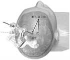
图1是用于术中MRI引导的双侧立体定向神经外科手术的MRI兼容的机器人的图像。Figure 1 is an image of an MRI-compatible robot for intraoperative MRI-guided bilateral stereotactic neurosurgery.
图2a是示出两个(双侧)操纵器的图,它们在MRI头部线圈的受限空间内附接在颅骨上且以两个极端配置完全伸展。Figure 2a is a diagram showing two (bilateral) manipulators attached to the skull and fully extended in two extreme configurations within the confined space of an MRI head coil.
图2b是具有两个可能配置的瞄准大脑目标的单个操纵器的图。Figure 2b is a diagram of a single manipulator targeting brain targets with two possible configurations.
图3是示出双侧立体定向操纵器的机构的图。Figure 3 is a diagram showing the mechanism of a bilateral stereotaxic manipulator.
图4是示出双侧立体定向操纵器的矢状面的图。Figure 4 is a diagram showing a sagittal plane of a bilateral stereotaxic manipulator.
图5是示出集成用于针插入的针引导部的线性致动器的图。FIG. 5 is a diagram showing a linear actuator integrating a needle guide for needle insertion.
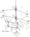
图6是单个操纵器的运动图,具有分别定义在壳基部和针尖端的坐标系ψo和ψE。Figure 6 is a motion diagram of a single manipulator with coordinate systemsψo andψE defined at the base of the shell and the tip of the needle, respectively.
图7是1自由度致动设计的图像和示意图。Figure 7 is an image and schematic diagram of a 1 degree of freedom actuation design.
图8a是嵌入有基于MR的追踪器的针引导部的图像。图8b是脑模体(以冠状视图)的MR图像,通过对应的亮点显示了两个追踪标记。图8c以冠状视图示出了高对比度标记上增强的仪器的虚拟配置。Figure 8a is an image of a needle guide embedded with an MR-based tracker. Figure 8b is an MR image of the brain phantom (in coronal view) showing two tracking markers with corresponding bright spots. Figure 8c shows the virtual configuration of the instrument enhanced on the high-contrast marker in a coronal view.
图9是示出MRI引导的机器人辅助立体定向的系统示意图。9 is a system schematic diagram illustrating MRI-guided robotic-assisted stereotaxic.
图10是当机器人置于等深点(isocenter)且在不同条件下操作时的,在T2加权快速自旋回波序列下的信噪比模体的MRI图像。Figure 10 is an MRI image of a signal-to-noise ratio phantom under a T2-weighted fast spin echo sequence when the robot is placed at the isocenter and operated under different conditions.
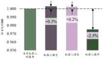
图11是信噪比(SNR)测试结果的曲线图。Figure 11 is a graph of the signal-to-noise ratio (SNR) test results.
图12a示出了常规的立体定向神经外科手术的外科手术流程。图12b示出了MRI引导的机器人辅助的立体定向神经外科手术的外科手术流程。Figure 12a shows the surgical flow of conventional stereotaxic neurosurgery. Figure 12b shows the surgical procedure for MRI-guided robot-assisted stereotactic neurosurgery.
图13是力位移的曲线图,示出了在四个预加载水平下的致动模块的传动刚度。Figure 13 is a graph of force displacement showing the drive stiffness of the actuation module at four preload levels.
具体实施方式Detailed ways
本发明的实施例设计为执行双侧仪器导航。在一个实施例中,本发明用于在手术的术中阶段期间的MRI引导的脑深部刺激术(DBS)。图3中示出了所提出的机器人操纵器的CAD模型和部件。并联机构在定位精确度和刚度方面具有优势。机器人的平面位置由两个致动的旋转接头和三个被动的旋转接头控制。该设计使两个操纵器各具有4个自由度、双侧设置的双层五连杆。Embodiments of the present invention are designed to perform bilateral instrument navigation. In one embodiment, the present invention is used for MRI-guided deep brain stimulation (DBS) during the intraoperative phase of surgery. The CAD model and components of the proposed robotic manipulator are shown in Figure 3. Parallel mechanisms have advantages in positioning accuracy and stiffness. The planar position of the robot is controlled by two actuated swivels and three passive swivels. The design enables two manipulators each with 4 degrees of freedom, double-layer five-links arranged on both sides.
操纵器包括至少一个刚性臂、至少一个外壳、以及至少一个安装基部,其经由至少一个安装单元(优选骨螺钉)固定至颅骨。所有锚定部位均远离矢状缝,以避免可能损伤下方的关键结构。在本发明的实施例中,臂的最低表面可以在钻孔上方约20-30mm,这取决于患者特定的颅骨曲率和其锚定部位(例如,参见图4)。保留入口点处的该暴露空间以供医生观察。出于多功能性,可以根据术前图像为患者量身定制安装基部。可以将所有的外壳手动插入并用安装基部固定。保留表面上的槽以用于附接配准标记。还形成了通道,以允许固定护套的端部,以更好地进行腱绳(tendon)布线。外壳内的回转接头由此可由腱绳致动。两个球形接头在前臂的远端处并入。针引导部通过这两个接头定向,并且用上接头轴向固定。在将针穿过由双层操纵器的两个端部执行器保持的套管插入之前,可以由针止动部预设允许的插入深度。软质材料也嵌入在套管/针止动部的内部,以通过引起滑动摩擦来限制针的线性运动。The manipulator comprises at least one rigid arm, at least one housing, and at least one mounting base, which is fixed to the skull via at least one mounting unit, preferably a bone screw. All anchoring sites are positioned away from the sagittal suture to avoid possible damage to underlying critical structures. In embodiments of the present invention, the lowest surface of the arm may be approximately 20-30 mm above the burr hole, depending on the patient's specific skull curvature and its anchorage site (eg, see Figure 4). This exposed space at the entry point is reserved for physician observation. For versatility, the mounting base can be tailored to the patient based on preoperative images. All housings can be manually inserted and secured with mounting bases. The grooves on the surface are reserved for attaching registration marks. Channels are also formed to allow securing the end of the sheath for better tendon routing. The swivel joint in the housing can thus be actuated by the chord. Two ball joints are incorporated at the distal end of the forearm. The needle guide is oriented by these two joints and is axially fixed with the upper joint. The allowable insertion depth can be preset by the needle stop prior to insertion of the needle through the cannula held by the two end effectors of the dual layer manipulator. A soft material is also embedded inside the cannula/needle stop to limit linear movement of the needle by causing sliding friction.
采用短腱绳驱动的设计旨在达到严格的标准,不仅在头部线圈施加的空间限制的方面,而且在可能会使患者感到不适的重量的方面。图7示出了MRI室中的从动操纵器,该从动操纵器与一对液压传动单元22连线,该一对液压传动单元22与控制室中的另一对液压传动单元连接。从动装置的这种紧凑设计可以使运动惯性最小化,并有助于在受限的工作空间中的操纵灵活性。它仍然能够施加由液压马达产生的有希望的水平的扭矩/力。部件可以通过3D打印来制造和/或由聚合物组成。The design with short tendon drive is designed to meet stringent standards, not only in terms of the space constraints imposed by the head coil, but also in terms of weight that may be uncomfortable for the patient. Figure 7 shows a driven manipulator in the MRI room wired to a pair of hydraulic transmission units 22 connected to another pair of hydraulic transmission units in the control room. This compact design of the follower minimizes motion inertia and facilitates maneuverability in confined workspaces. It is still capable of applying the desired level of torque/force produced by the hydraulic motor. Parts can be manufactured by 3D printing and/or composed of polymers.
对于1自由度的致动,如图7所示,操纵器基部接头和液压单元之间分开的距离可以小于200mm,并与紧密穿过护套24的一圈薄腱绳相连接。护套材料是轴向不可压缩的,以防止施加在颅骨上的突然/过大的拉力。即使在高拉伸强度下,它也以足够的柔韧性支持腱绳的路线。适当的润滑可以减少腱绳-护套摩擦。两个惰轮26也可以用于预加载张力,以便减少任何机械间隙。For 1 degree of freedom actuation, as shown in FIG. 7 , the distance between the manipulator base joint and the hydraulic unit may be less than 200mm apart and connected with a thin loop of tendon that passes tightly through the sheath 24 . The sheath material is axially incompressible to prevent sudden/excessive pulling forces on the skull. Even at high tensile strength, it supports the course of the chord with sufficient flexibility. Proper lubrication can reduce chord-sheath friction. Two idler pulleys 26 can also be used to preload tension to reduce any mechanical play.
主(其可以位于控制室中)和从(其可以位于MRI室中)致动系统可以包括两个相同的线性到旋转机构(例如,参见图7)。液压动力来自电动机29,并经由一对半刚性长管传动。这些设计参数对传动动力学的性能至关重要。建议使用长度较短且直径较大的管道,其可减少流体摩擦、传动延迟和能量损失。管道可以填充不可压缩的液体28(例如水)并通过两个房间之间的波导。可以预加载液体压力,以将活塞17推向小齿轮和齿条齿轮,从而使它们的齿保持稳定接触而无间隙。The master (which may be located in the control room) and slave (which may be located in the MRI room) actuation system may include two identical linear-to-rotary mechanisms (eg, see Figure 7). Hydraulic power comes from an electric motor 29 and is driven via a pair of semi-rigid long tubes. These design parameters are critical to the performance of the drive dynamics. Shorter lengths and larger diameter pipes are recommended to reduce fluid friction, transmission delay and energy loss. The pipes can be filled with an incompressible liquid 28 (eg water) and pass through the waveguide between the two rooms. Hydraulic pressure can be preloaded to push the piston 17 towards the pinion and rack gears so that their teeth maintain stable contact without play.
包括滚动膜片27的密封件用于密封气缸,并在传动期间产生可忽略的滑动摩擦。膜片27的壁可以用织物增强以用于高流体压力。由此产生的传动响应和功率效率可以超过带O形环的常规液压密封,O形环的滑动摩擦是显著的。Seals including rolling diaphragms 27 are used to seal the cylinder and generate negligible sliding friction during transmission. The walls of the diaphragm 27 may be reinforced with fabric for high fluid pressures. The resulting transmission response and power efficiency can exceed conventional hydraulic seals with O-rings, the sliding friction of which is significant.
图2-4示出了本发明的实施例的CAD模型和部件。并联机构在定位精确度和刚度方面具有优势。平面位置由两个致动的旋转接头和三个被动的旋转接头控制。该设计产生两个4自由度、双侧设置的双层五连杆操纵器。在一个实施例中,操纵器包括刚性臂、四个外壳33、以及安装基部39,安装基部39经由四个骨螺钉固定至颅骨,每侧两个骨螺钉。锚定部位与矢状缝间隔开,以避免可能对患者造成损伤。安装基部39可以针对特定患者量身定制。可以将外壳33手动插入并用安装基部39固定。可以保留表面以附接配准标记。可以形成通道38,以允许固定护套的端部,以更好地进行腱绳布线。外壳内的回转接头可由腱绳致动。两个球形接头41可以在前臂32的远端处并入。针引导部31可以通过这两个接头来定向,并且用上接头轴向固定。在通过套管插入针12之前,可以通过针止动部34预先设置允许的插入深度。软质材料35也可以嵌入套管内,以通过引起滑动摩擦来限制针12的线性运动。2-4 illustrate CAD models and components of embodiments of the present invention. Parallel mechanisms have advantages in positioning accuracy and stiffness. The plane position is controlled by two actuated swivels and three passive swivels. The design yields two dual-layer five-link manipulators with 4 degrees of freedom, arranged on both sides. In one embodiment, the manipulator includes a rigid arm, four housings 33, and a mounting base 39 secured to the skull via four bone screws, two on each side. The anchoring site is spaced from the sagittal suture to avoid possible injury to the patient. The mounting base 39 can be tailored to a particular patient. The housing 33 can be manually inserted and secured with the mounting base 39 . Surfaces can be reserved for attaching registration marks. Channels 38 may be formed to allow securing the end of the sheath for better chord routing. The swivel joint within the housing can be actuated by the tendon. Two ball joints 41 may be incorporated at the distal end of the forearm 32 . The needle guide 31 can be oriented by these two joints and fixed axially with the upper joint. The allowable insertion depth may be preset by the needle stop 34 prior to insertion of the needle 12 through the cannula. A soft material 35 may also be embedded within the cannula to limit the linear movement of the needle 12 by causing sliding friction.
为了自动插入针,可以将线性致动器集成到针引导部中。它可以由类似的主从致动器机构来驱动(例如,参见图5)。针引导部将针约束在平移运动中。可以使用由辊组成的摩擦驱动,其中一个提供动力(驱动辊),另一个被动从动(从动辊)。高摩擦是由包围辊的软质材料的粗糙表面确保的。它们可以向内或向外旋转以插入或取出针。两个辊轴之间的距离小于软质辊的外径,以保持彼此相对的径向推动力并增加对针的夹持力。腱绳连接到驱动辊,而从动致动器的其余部分可以全部放置在手术台上。For automatic needle insertion, a linear actuator can be integrated into the needle guide. It can be driven by a similar master-slave actuator mechanism (see eg Figure 5). The needle guide restrains the needle in translational motion. It is possible to use a friction drive consisting of rollers, one of which provides power (the drive roller) and the other is driven passively (the driven roller). High friction is ensured by the rough surface of the soft material surrounding the rollers. They can be rotated in or out to insert or remove the needle. The distance between the two roller shafts is smaller than the outer diameter of the soft roller to maintain the radial pushing force against each other and increase the pinching force on the needle. The tendon is attached to the drive roller, while the rest of the driven actuator can all be placed on the operating table.
在本发明的实施例中,手术机器人包括安装在单个安装基部上的两个操纵器。如图3所示,两个操纵器设置在安装基部39上以允许同时和独立的双侧操作。每个操纵器包括基于腱绳的下致动器和堆叠在下致动器的顶部上的基于腱绳的上致动器。安装基部39可以连接到每个下致动器的外壳33。上致动器和下致动器的外壳33可以各自具有腱绳通道38,以允许腱绳穿过并致动每个致动器的两个旋转接头。每个旋转接头可以连接到上臂37的近端。每个前臂的远端可以连接到被动接头。每个被动接头可以连接到前臂32,且每个致动器的两个前臂32可以与球形接头41连接在一起。针引导部31可以插入上致动器和下致动器的球形接头41中。可以用手和/或线性致动器将针插入针引导部31中并与针止动部34装配以在手术期间进行辅助。基于MR的追踪器30可以嵌入针引导部31中。安装基部39可以经由四个骨螺钉固定至颅骨,安装基部39的每一侧两个骨螺钉。In an embodiment of the invention, the surgical robot includes two manipulators mounted on a single mounting base. As shown in Figure 3, two manipulators are provided on the mounting base 39 to allow simultaneous and independent bilateral operation. Each manipulator includes a lower chord-based actuator and an upper chord-based actuator stacked on top of the lower actuator. A mounting base 39 may be attached to the housing 33 of each lower actuator. The housings 33 of the upper and lower actuators may each have chord channels 38 to allow the chords to pass through and actuate the two swivel joints of each actuator. Each swivel can be connected to the proximal end of the upper arm 37 . The distal end of each forearm can be connected to a passive joint. Each passive joint can be connected to the forearm 32 and the two forearms 32 of each actuator can be connected together with the ball joint 41 . The needle guide 31 can be inserted into the ball joints 41 of the upper and lower actuators. The needle can be inserted into needle guide 31 by hand and/or a linear actuator and assembled with needle stop 34 to assist during surgery. The MR-based tracker 30 may be embedded in the needle guide 31 . The mounting base 39 may be secured to the skull via four bone screws, two on each side of the mounting base 39 .
图6绘示了一个双层操纵器的运动图。在外壳基部和针尖端处分别定义了两个坐标系ψo和ψE。套管分别从上层和下层由两个被动接头Ju5和Jl5连接,套管的位置可以分别通过包含点Puk和Plk的上层和下层的独立(x-y)平面运动来操纵。这些点表示对于k=1,2,3,4的对应的接头Juk和Jlk的2D坐标,可以通过以下方程组求解:Figure 6 shows a motion diagram of a two-layer manipulator. Two coordinate systemsψo andψE are defined at the base of the housing and the tip of the needle, respectively. The casing is connected by two passive jointsJu5 andJ15 from the upper and lower layers, respectively, and the position of the casing can be manipulated by independent (xy) plane movements of the upper and lower layers containing pointsPuk andPlk , respectively. These points represent the 2D coordinates of the corresponding jointsJuk and Jlkfor k=1, 2, 3, 4, which can be solved by the following system of equations:

水平偏移a分离两个致动的接头,垂直偏移b分离上层和下层。可以将致动的接头的阵列定义为q=[qu1,qu2,qu3,qu4]T,可以在该五连杆机构中找到两种类型的两个奇点。第一个是在形状为共线时发生的(例如,接头Jl3,Jl4,Jl5成一条线),第二个是仅当臂完全伸展时发生的。为了防止前臂的对共线,可以利用相对旋转的机械限制。例如,Jl5可以总是位于Jl1,Jl2,Jl3和Jl4的四边形区域之外。为了求解逆运动学,针的取向可以由单位

假设插入深度du和dl分别定义了从接头Ju5和Jl5到大脑目标的线性距离。用作两个操纵器的最终端执行器的针尖端42,pe的位置可以计算为:The insertion depths du and dl are assumed to define the linear distances from the junctionsJu5 andJl5 to the brain target, respectively. The position of the needle tip 42,pe used as the final end effector of the two manipulators, can be calculated as:

举例来说,为了找到四个致动的接头角度,q=[qu1,qu2,qu3,qu4]T,基于相对于MR图像坐标的所需的针位置,需要机器人和图像坐标系之间的共配准。计算的参数(即,pe和

坐标puf和plf分别属于三角形ΔJu1,Ju3,Ju5和ΔJl1,Jl3,Jl5,角度∠Ju3Ju1Ju5和∠Ju4Ju2Ju5(表示为θu1,θu2)可以分别使用余弦定律在三角形ΔJu1,Ju3,Ju5和ΔJl2,Jl4,Jl5中通过下式来求解:Coordinates puf and plf belong to triangles ΔJu1 , Ju3,Ju5 and ΔJl1 , Jl3 , Jl5 , respectively, and angles ∠Ju3 Ju1 Ju5 and ∠Ju4 Ju2 Ju5 (denoted as θu1 , θu2 ) can be solved in triangles ΔJu1 ,Ju3 ,Ju5 and ΔJl2 , Jl4 , Jl5 using the cosine law by the following equations, respectively:


为了避免第二种奇点,接头Ju3,Ju4例如可能位于ΔJu1,Ju3,Ju5以外,使得qu1=θu1+αu1且qu2=π–(θu2+αu2)。本领域普通技术人员应该理解,其他致动参数可以通过类似的过程来求解。To avoid the second kind of singularity, the jointsJu3 ,Ju4 may for example lie outsideΔJu1 ,Ju3 ,Ju5 , such thatqu1 = θu1 +αu1 andqu2 =π−(θu2 +αu2 ). One of ordinary skill in the art will understand that other actuation parameters can be solved by a similar process.
首先,将基于MR的无线追踪引入这种机器人立体定向(例如,参见图8)。图9示出了MRI引导机器人立体定向的系统设置。两个或更多个追踪器30可以嵌入针引导部31(图8a)中。可以将注入了MRI可见液体的软质中空环附接到钻孔,以定位入口点并立即进行轨迹规划。3D扰相梯度回波(SPGR)序列可用于评估针引导部的位置和取向。然后可以将针插入并以相同的成像序列进行扫描。图8b和8c以冠状视图示出了所得的MR图像和3D重建。追踪器和插入的针都可以可视化。两个追踪器的信号强度与背景和脑模体的信号强度形成鲜明对比。通过在较低的翻转角度(例如1°)下进行专门的激励,这种对比可以进一步增强,这样可以使背景信号最小化。First, MR-based wireless tracking was introduced into this robotic stereotaxic (eg, see Figure 8). Figure 9 shows the system setup for MRI-guided robotic stereotaxy. Two or more trackers 30 may be embedded in the needle guide 31 (Fig. 8a). A soft hollow ring infused with MRI-visible fluid can be attached to the borehole to locate the entry point and allow immediate trajectory planning. A 3D Spoiler Gradient Echo (SPGR) sequence can be used to assess the position and orientation of the needle guide. The needle can then be inserted and scanned in the same imaging sequence. Figures 8b and 8c show the resulting MR images and 3D reconstructions in coronal view. Both the tracker and the inserted needle can be visualized. The signal intensities of the two trackers contrasted sharply with those of the background and brain phantoms. This contrast can be further enhanced by dedicated excitation at lower flip angles (eg 1°), which minimizes background signal.
图10示出了当机器人放置在体模旁边的等深点并在不同条件下操作时,体模在快速自旋回波序列下的MRI图像。第一条件是“没有机器人”,即,只有体模放置在扫描仪中。第二条件是“机器人静态”,即机器人已被引入扫描仪,但所有电源已关闭。在第三条件下,即“机器人通电”,电源已打开,但是机器人是静态的。第四条件是“机器人运动”,其为机器人处于正常操作状态时。比较了与两个条件(基线和机器人操作)对应的图像。强度变化在30%或以上的像素被视为伪影。这些伪影将在二进制图中显示为白色像素。在体模区域内未观察到伪影。根据ASTM标准所定义的,它表示机器人产生零伪影的操作。Figure 10 shows MRI images of phantoms under fast spin-echo sequences when the robot is placed at an isobar next to the phantom and operated under different conditions. The first condition is "no robot", ie only the phantom is placed in the scanner. The second condition is "robot static", i.e. the robot has been introduced into the scanner but all power is turned off. In the third condition, "robot powered on", the power is on, but the robot is static. The fourth condition is "robot motion", which is when the robot is in a normal operating state. Images corresponding to two conditions (baseline and robot manipulation) were compared. Pixels with an intensity change of 30% or more are considered artifacts. These artifacts will appear as white pixels in the binary image. No artifacts were observed within the phantom region. As defined by the ASTM standard, it represents the operation of the robot that produces zero artifacts.
在本发明的实施例中,机器人可以包括两个操纵器,其安装在形成在颅骨中的两个钻孔上。每个操纵器可以在由每个对应的钻孔接近的仪器上提供4个自由度操纵,包括在颅骨表面上沿着x-y平面的俯仰、滚转和偏移。这有助于将所需的直线轨迹对准大脑目标。In an embodiment of the invention, the robot may include two manipulators mounted on two bore holes formed in the skull. Each manipulator can provide 4 degrees of freedom manipulation on the instrument approached by each corresponding borehole, including pitch, roll, and deflection along the x-y plane on the surface of the skull. This helps to align the desired straight trajectory to the brain target.
为了便于双侧立体定向操纵,本发明的实施例可以设计为:i)紧凑,使得可以由于头部线圈引起的严格尺寸限制内将机器人固定在颅骨上,ii)能够自动进行轨迹规划和仪器对准,iii)独立地进行双侧操纵,以及iv)通过确保机器人平台中不包含任何磁性部件,来满足MRI与ASTM F2503标准的MRI兼容性。通常,机器人不会在感兴趣区域(ROI)内引起明显的伪影或信噪比(SNR)的显著降低。To facilitate bilateral stereotaxic manipulation, embodiments of the present invention can be designed to: i) be compact so that the robot can be fixed to the skull within the tight size constraints due to head coils, ii) enable automated trajectory planning and instrumentation , iii) independently perform bilateral manipulation, and iv) meet MRI compatibility with ASTM F2503 standard by ensuring that no magnetic components are included in the robotic platform. Typically, the robot does not cause noticeable artifacts or significant reduction in signal-to-noise ratio (SNR) within the region of interest (ROI).
图12示出了常规的和MRI引导的机器人辅助的立体定向神经外科手术的工作流程。通过实时MRI引导和机器人操纵,可以消除患者位置、配准和脑移位等方面的目标错误。可以显著减少手术时间以及手术费用。它可以涉及MRI扫描、使用机器人/MRI兼容的仪器以及机器人操作所需的额外人力。Figure 12 shows the workflow of conventional and MRI-guided robotic-assisted stereotactic neurosurgery. Targeting errors in patient position, registration, and brain displacement can be eliminated through real-time MRI guidance and robotic manipulation. The operation time and cost of operation can be significantly reduced. It can involve MRI scans, the use of robotic/MRI-compatible instruments, and the extra manpower required for robotic manipulation.
图12a示出了常规立体定向神经外科手术的可能的外科手术流程。常规外科手术可分为术前、术中和术后阶段。术前即刻阶段可发生在术前阶段和术中阶段之间。在术前阶段期间,医务人员可以通过执行MRI、计算机断层(CT)扫描、血液测试以及解决患者可能存在任何焦虑,来对患者进行生理和心理评估。医务人员可以另外制定计划,以最好地达到手术的理想结果。Figure 12a shows a possible surgical procedure for conventional stereotaxic neurosurgery. Conventional surgery can be divided into preoperative, intraoperative and postoperative phases. The immediate preoperative phase can occur between the preoperative and intraoperative phases. During the preoperative phase, medical personnel can perform a physical and psychological assessment of the patient by performing MRIs, computed tomography (CT) scans, blood tests, and addressing any anxiety the patient may have. Medical staff can make additional plans to best achieve the desired outcome of the surgery.
在术前即刻阶段期间,可以将立体定向框架连同标记一起附接至患者的头部。可以对佩戴立体定向框架的患者进行CT扫描,并可以在CT扫描图像和任何术中工具位置之间进行配准。之后,可以将患者转移到手术室或手术厅。During the immediate preoperative phase, the stereotaxic frame can be attached to the patient's head along with the markers. CT scans can be performed on patients wearing a stereotactic frame and registration can be performed between CT scan images and any intraoperative tool positions. After that, the patient can be transferred to the operating room or operating theatre.
在术中阶段期间,医务人员可以在患者的头部上设置立体定向框架。可以在病人的颅骨上钻取或刮取钻孔。可以通过钻孔将针手动插入患者的大脑。如果患者正在接受脑深部刺激术,则可以植入微电极以监测对刺激的电响应。如果达到了预期的目标,则可以将针移除并密封钻孔。但是,如果尚未达到所需的目标,则可以重新插入针并重复该过程。During the intraoperative phase, medical personnel may place a stereotaxic frame on the patient's head. Drill holes can be drilled or scraped in the patient's skull. The needle can be manually inserted into the patient's brain through a burr hole. If the patient is undergoing deep brain stimulation, microelectrodes can be implanted to monitor the electrical response to stimulation. If the desired goal is achieved, the needle can be removed and the drill hole sealed. However, if the desired goal has not been achieved, the needle can be reinserted and the process repeated.
手术完成后,可以将患者转出手术室并监视手术后的效果。可以在术后阶段期间进行MRI扫描,医务人员可以确定是否需要任何其他治疗。After the procedure is complete, the patient can be transferred out of the operating room and monitored for post-operative outcomes. MRI scans can be done during the postoperative period, and medical staff can determine if any other treatments are needed.
图12b示出了MRI引导的机器人辅助的立体定向神经外科手术的外科手术流程。术前阶段与常规的立体定向神经外科手术术前阶段相似。术前阶段结束后,可以将患者转移到手术室。MRI引导的机器人可以用螺钉固定到患者的颅骨。可以执行MRI扫描,并且可以将MRI图像与机器人坐标系配准。医务人员可以在患者的颅骨中形成一个或多个钻孔。外科医生可以使用基于MRI的追踪和图像,通过操纵机器人的每个致动器来引导患者大脑中的针。如果达到了预期的目标,则可以将针移除并密封钻孔。但是,如果尚未达到所需的目标,则可以重新插入针并重复该过程。手术完成后,可以将患者转出手术室并监视手术后的效果。可以在术后阶段期间进行MRI扫描,医务人员可以确定是否需要任何其他治疗。Figure 12b shows the surgical procedure for MRI-guided robot-assisted stereotactic neurosurgery. The preoperative phase is similar to that of conventional stereotactic neurosurgery. After the preoperative phase is over, the patient can be transferred to the operating room. The MRI-guided robot can be screwed to the patient's skull. An MRI scan can be performed and the MRI image can be registered with the robot coordinate system. Medical staff can create one or more drill holes in the patient's skull. Surgeons can use MRI-based tracking and images to guide needles in a patient's brain by manipulating each of the robot's actuators. If the desired goal is achieved, the needle can be removed and the drill hole sealed. However, if the desired goal has not been achieved, the needle can be reinserted and the process repeated. After the procedure is complete, the patient can be transferred out of the operating room and monitored for post-operative outcomes. MRI scans can be done during the postoperative period, and medical staff can determine if any other treatments are needed.
本文描述的方法和过程可以体现为代码和/或数据。本文描述的软件代码和数据可以存储在一个或多个机器可读介质(例如,计算机可读介质)上,该机器可读介质可以包括可以存储代码和/或数据以供计算机系统使用的任何设装置或介质。当计算机系统和/或处理器读取并执行存储在计算机可读介质上的代码和/或数据时,计算机系统和/或处理器执行体现为存储在计算机可读存储器中的数据结构和代码的方法和过程。The methods and processes described herein may be embodied as code and/or data. The software code and data described herein can be stored on one or more machine-readable media (eg, computer-readable media), which can include any device that can store the code and/or data for use by a computer system device or medium. When the computer system and/or processor reads and executes the code and/or data stored on the computer readable medium, the computer system and/or processor executes the data structures and code embodied in the computer readable memory method and process.
本领域技术人员应该理解,计算机可读介质包括可用于存储信息的可移动和不可移动结构/装置,例如计算机可读指令、数据结构、程序模块以及计算系统/环境使用的其他数据。计算机可读介质包括但不限于诸如随机存取存储器(RAM、DRAM、SRAM)之类的易失性存储器;以及诸如闪存之类的非易失性存储器,各种只读存储器(ROM、PROM、EPROM、EEPROM),磁和铁磁/铁电存储器(MRAM、FeRAM),以及磁和光存储装置(硬盘、磁带、CD、DVD);网络装置;或其他已知或以后开发的能够存储计算机可读信息/数据的介质。计算机可读介质不应被解释或理解为包括任何传播的信号。本发明的计算机可读介质可以是例如光盘(CD)、数字视频光盘(DVD)、闪存装置、易失性存储器、或硬盘驱动器(HDD),例如外部HDD或计算装置的HDD,但是实施例不限于此。计算装置可以是例如膝上型计算机、台式计算机、服务器、手机或平板电脑,但是实施例不限于此。Those skilled in the art will understand that computer readable media includes removable and non-removable structures/devices that can be used for storage of information such as computer readable instructions, data structures, program modules, and other data used by a computing system/environment. Computer readable media include, but are not limited to, volatile memory such as random access memory (RAM, DRAM, SRAM); and nonvolatile memory such as flash memory, various read only memories (ROM, PROM, EPROM, EEPROM), magnetic and ferromagnetic/ferroelectric memory (MRAM, FeRAM), and magnetic and optical storage devices (hard disk, tape, CD, DVD); network devices; or other known or later developed capable of storing computer-readable medium of information/data. Computer-readable media should not be construed or understood to include any propagated signal. The computer readable medium of the present invention may be, for example, a compact disc (CD), a digital video disc (DVD), a flash memory device, a volatile memory, or a hard disk drive (HDD), such as an external HDD or HDD of a computing device, but the embodiment does not limited to this. The computing device may be, for example, a laptop computer, a desktop computer, a server, a cell phone, or a tablet computer, although embodiments are not limited thereto.
本发明包括但不限于以下示例性实施例。The present invention includes, but is not limited to, the following exemplary embodiments.
实施例1.用于磁共振成像引导干预的手术机器人,包括:
操纵器,包括基于腱绳的上致动器和基于腱绳的下致动器;Manipulators, including a chord-based upper actuator and a chord-based lower actuator;
安装基部,连接到下致动器;a mounting base, connected to the lower actuator;
针引导部;以及needle guides; and
设置在针引导部内的针;a needle disposed within the needle guide;
其中每个致动器包括:Each of these actuators includes:
外壳,具有多个开口以允许腱绳穿过,shell, with openings to allow chords to pass through,
两个旋转接头,连接到外壳,Two swivel joints, attached to the housing,
两个上臂,分别连接到两个旋转接头,Two upper arms, connected to two swivel joints, respectively,
两个前臂,分别通过被动接头在每个前臂的近端处连接到两个上臂,被动球形接头,在每个前臂的远端处连接两个前臂,其中针引导部设置在上致动器和下致动器的球形接头内,并且其中安装基部具有用于骨安装的多个螺钉孔。Two forearms, connected to the two upper arms at the proximal end of each forearm by passive joints, respectively, and passive ball joints, connected to the two forearms at the distal end of each forearm, wherein needle guides are provided on the upper actuator and Inside the ball joint of the lower actuator, and wherein the mounting base has a plurality of screw holes for bone mounting.
实施例2.如实施例1所述的手术机器人,还包括设置在针上的针止动部和/或线性致动器。Embodiment 2. The surgical robot of
实施例3.如实施例1-2中任一项所述的手术机器人,还包括设置在针引导部上的一个或多个基于MR的追踪器。Embodiment 3. The surgical robot of any of Embodiments 1-2, further comprising one or more MR-based trackers disposed on the needle guide.
实施例4.如实施例1-3中任一项所述的手术机器人,其中机器人包括多个操纵器。Embodiment 4. The surgical robot of any of Embodiments 1-3, wherein the robot includes a plurality of manipulators.
实施例5.如实施例1-3中任一项所述的手术机器人,还包括:Embodiment 5. The surgical robot of any one of embodiments 1-3, further comprising:
插入上致动器的外壳中的两个腱绳;Two tendons inserted into the housing of the upper actuator;
插入下致动器的外壳中的两个腱绳;以及two tendons inserted into the housing of the lower actuator; and
两个或更多个线轴,分别连接到每个腱绳,two or more spools, attached to each tendon individually,
其中每个腱绳分别连接到每个外壳的每个旋转接头。Each of the tendons is connected to each of the swivel joints of each housing, respectively.
实施例6.如实施例5所述的手术机器人,其中每个腱绳分别穿过护套。Embodiment 6. The surgical robot of Embodiment 5, wherein each tendon is individually threaded through the sheath.
实施例7.如实施例6所述的手术机器人,还包括:
第一套件,包括多个小齿轮和齿条齿轮,The first kit, including multiple pinions and rack and pinions,
其中第一套件的每个小齿轮分别联接到每个线轴;以及wherein each pinion of the first set is coupled to each spool, respectively; and
多个液压管,每个管分别在第一端处连接到每个齿条齿轮,且填充有流体,a plurality of hydraulic tubes, each connected at a first end to each of the rack and pinion, and filled with fluid,
其中流体和第一套件的每个齿条齿轮由滚动膜片隔开。Wherein the fluid and each rack and pinion of the first set are separated by a rolling diaphragm.
实施例8.如实施例7所述的手术机器人,还包括:Embodiment 8. The surgical robot of
第二套件,包括多个小齿轮和齿条齿轮,Second kit, including multiple pinions and rack and pinion,
其中第二套件的每个小齿轮联接到马达,where each pinion of the second kit is coupled to a motor,
其中第二套件的每个齿条分别连接到每个液压管的相对端,并且wherein each rack of the second set is connected to the opposite end of each hydraulic pipe, and
其中流体和第二套件的每个齿条齿轮由滚动膜片隔开。Wherein the fluid and each rack and pinion of the second set are separated by a rolling diaphragm.
实施例9.如实施例1-8中任一项所述的手术机器人,其中手术机器人安装在颅骨上。Embodiment 9. The surgical robot of any of embodiments 1-8, wherein the surgical robot is mounted on a skull.
实施例10.如实施例1-9中任一项所述的手术机器人,其中针是刚性的直的手术仪器,例如DBS针。
实施例11.用于磁共振成像引导干预的手术机器人,包括:Example 11. A surgical robot for magnetic resonance imaging guided intervention, comprising:
两个操纵器,每个操纵器包括基于腱绳的上致动器和基于腱绳的下致动器;two manipulators, each manipulator including an upper chord-based actuator and a lower chord-based actuator;
每个下致动器连接到安装基部;each lower actuator is connected to the mounting base;
两个针引导部;以及two needle guides; and
两个针,每个针设置在相应的针引导部内,Two needles, each set in a corresponding needle guide,
其中每个致动器包括:Each of these actuators includes:
外壳,具有多个开口以允许腱绳穿过,shell, with openings to allow chords to pass through,
两个旋转接头,连接到外壳,Two swivel joints, attached to the housing,
两个上臂,分别连接到两个旋转接头,Two upper arms, connected to two swivel joints, respectively,
两个前臂,分别通过被动接头在每个前臂的近端处连接到两个上臂,以及two forearms, each connected to the two upper arms at the proximal end of each forearm by passive joints, and
被动球形接头,在每个前臂的远端处连接两个前臂,A passive ball joint that connects the two forearms at the distal end of each forearm,
其中针引导部中的一个分别设置在每个操纵器的上致动器和下致动器二者的球形接头内,并且wherein one of the needle guides is provided in the ball joint of both the upper and lower actuators of each manipulator, respectively, and
其中安装基部具有用于骨安装的多个螺钉孔。Wherein the mounting base has a plurality of screw holes for bone mounting.
实施例12.如实施例11所述的手术机器人,还包括两个针止动部和/或两个线性致动器,每个针止动部/线性致动器设置在相应的针上。Embodiment 12. The surgical robot of Embodiment 11, further comprising two needle stops and/or two linear actuators, each needle stop/linear actuator disposed on a corresponding needle.
实施例13.如实施例11-12中任一项所述的手术机器人,还包括两个或更多个基于MR的追踪器,每个基于MR的追踪器设置在相应的针引导部上。Embodiment 13. The surgical robot of any of Embodiments 11-12, further comprising two or more MR-based trackers, each MR-based tracker disposed on a corresponding needle guide.
实施例14.如实施例11-13中任一项所述的手术机器人,还包括:Embodiment 14. The surgical robot of any one of Embodiments 11-13, further comprising:
插入每个上致动器的外壳中的两个腱绳;Two tendons inserted into the housing of each upper actuator;
插入每个下致动器的外壳中的两个腱绳;以及two tendons inserted into the housing of each lower actuator; and
两个或更多个线轴,分别连接到每个腱绳,two or more spools, attached to each tendon individually,
其中每个腱绳分别连接到每个外壳的每个旋转接头。Each of the tendons is connected to each of the swivel joints of each housing, respectively.
实施例15.如实施例14所述的手术机器人,其中每个腱绳分别穿过护套。
实施例16.如实施例11-15中任一项所述的手术机器人,还包括:Embodiment 16. The surgical robot of any of embodiments 11-15, further comprising:
第一套件,包括多个小齿轮和齿条齿轮,The first kit, including multiple pinions and rack and pinions,
其中第一套件的每个小齿轮分别联接到每个线轴;以及wherein each pinion of the first set is coupled to each spool, respectively; and
多个液压管,每个管分别在第一端处连接到每个齿条齿轮,且填充有流体,a plurality of hydraulic tubes, each connected at a first end to each of the rack and pinion, and filled with fluid,
其中流体和第一套件的每个齿条齿轮由滚动膜片隔开。Wherein the fluid and each rack and pinion of the first set are separated by a rolling diaphragm.
实施例17.如实施例11-16中任一项所述的手术机器人,还包括:Embodiment 17. The surgical robot of any one of Embodiments 11-16, further comprising:
第二套件,包括多个小齿轮和齿条齿轮,Second kit, including multiple pinions and rack and pinion,
其中第二套件的每个齿条分别连接到每个液压管的相对端,并且wherein each rack of the second set is connected to the opposite end of each hydraulic pipe, and
其中流体和第二套件的每个齿条齿轮由滚动膜片隔开。Wherein the fluid and each rack and pinion of the second set are separated by a rolling diaphragm.
实施例18.如实施例11-17中任一项所述的手术机器人,其中手术机器人安装在颅骨上。Embodiment 18. The surgical robot of any of Embodiments 11-17, wherein the surgical robot is mounted on the skull.
实施例19.如实施例11-18中任一项所述的手术机器人,其中针是直的刚性的手术仪器,例如DBS针。Embodiment 19. The surgical robot of any of Embodiments 11-18, wherein the needle is a straight rigid surgical instrument, such as a DBS needle.
通过以举例说明的方式给出的以下示例,可以更好地理解本发明及其许多优点。以下示例说明了本发明的一些方法、应用、实施例和变体。当然,它们不应被认为是对本发明的限制。可以相对于本发明进行许多改变和修改。The present invention and its many advantages may be better understood by the following examples, given by way of illustration. The following examples illustrate some methods, applications, embodiments and variations of the present invention. Of course, they should not be considered limitations of the invention. Numerous changes and modifications are possible with respect to the present invention.
示例1-传动刚度Example 1 - Transmission stiffness
对1自由度的致动进行了迭代测试。固定操纵器的上臂,以限制致动的接头的旋转。十个填充有蒸馏水的计量管用于连接主从液压单元。主单元由提供500个编码脉冲反馈的直流马达致动。直流马达也以14:1的比例减速,产生0.052°的旋转分辨率。使用灵敏度为5m/Nm的扭矩传感器测量外部负载。测试是在双向负载下进行的。为了研究不同流体压力水平下传动刚度的变化,管道中的传动液被分别预加载为0.5、1.0、1.5和2.0巴(bar)。逐渐增加外部负载,同时记录相应的活塞位移。Iterative testing was performed for actuation with 1 degree of freedom. The upper arm of the manipulator is secured to limit rotation of the actuated joint. Ten metering tubes filled with distilled water are used to connect the master and slave hydraulic units. The main unit is actuated by a DC motor that provides feedback of 500 coded pulses. The DC motor is also slowed down by a 14:1 ratio, resulting in a rotational resolution of 0.052°. The external load is measured using a torque sensor with a sensitivity of 5m/Nm. The test is performed under bidirectional load. To investigate the change in transmission stiffness at different fluid pressure levels, the transmission fluid in the pipes was preloaded at 0.5, 1.0, 1.5 and 2.0 bar, respectively. Gradually increase the external load while recording the corresponding piston displacement.
如图13所示,力位移图示出了随着预加载流体压力的增加,传动刚度的增加趋势。这可以归因于负载增加时液压管的增强的特氟龙材料刚度。使用最小二乘回归对数据进行线性拟合,这表明在2巴的预加载压力下,最大刚度系数可以达到24.35N/mm。As shown in Figure 13, the force-displacement plot shows an increasing trend in transmission stiffness as the preload fluid pressure increases. This can be attributed to the enhanced Teflon material stiffness of the hydraulic tubes as the load increases. A linear fit to the data using least squares regression shows that at a preload pressure of 2 bar, a maximum stiffness factor of 24.35 N/mm can be achieved.
示例2-针瞄准精确度Example 2 - Needle Aiming Accuracy
EM位置追踪系统用于测量实验设置中定义的任何点的3D坐标。模拟十个点作为STN目标,在塑料板上每侧五个。这些点在下层操纵器下方约100毫米处。这是颅骨下方的立体定向目标的典型深度。这些测量的目标坐标已与机器人坐标系配准。两个EM追踪线圈附接到一个机器人前臂,每层一个。在此瞄准任务中使用了直径与DBS套管相似的体模针。准确的针尖位置和取向是由固定在针的尖端处的两个5个自由度线圈计算得出的。The EM position tracking system was used to measure the 3D coordinates of any point defined in the experimental setup. Ten points were simulated as STN targets, five on each side of the plastic plate. These points are about 100mm below the lower manipulator. This is a typical depth for stereotaxic targets below the skull. The target coordinates for these measurements are registered with the robot coordinate system. Two EM tracking coils were attached to a robotic forearm, one for each layer. A phantom needle with a diameter similar to the DBS cannula was used in this targeting mission. The exact needle tip position and orientation is calculated from two 5-DOF coils fixed at the tip of the needle.
测量并计算了机器人和针引导部的配置以及针的插入深度。瞄准目标点后,手动插入针。测量从针尖端到目标的近端距离和从目标到针轴线的距离。对于每侧五个目标的针插入重复进行试验。瞄准精确度通过平均误差及其标准差进行量化,如表1所示。The configuration of the robot and needle guide and the needle insertion depth were measured and calculated. After aiming at the target point, insert the needle manually. Measure the proximal distance from the needle tip to the target and the distance from the target to the needle axis. The trial was repeated for needle insertion with five targets on each side. Aiming accuracy is quantified by the mean error and its standard deviation, as shown in Table 1.
表1针瞄准精确度测试Table 1 Needle Aiming Accuracy Test

示例3-基于MR的追踪测试Example 3 - MR based tracking test
将机器人安装在颅骨模型上并放置在头部线圈中并进行扫描。为了在MR图像中显示脑模体,用琼脂凝胶制作了“大脑”,以增强图像对比度来进行针瞄准。首先使用了两个薄的追踪线圈膜并将其嵌入在针引导部中。3D扰相梯度回波(SPGR)序列用于评估针引导部的位置和取向。序列参数列于表2。The robot is mounted on the skull model and placed in the head coil and scanned. To visualize the brain phantom in MR images, a "brain" was created from agar gel to enhance image contrast for needle aiming. Two thin tracer coil membranes were first used and embedded in the needle guide. A 3D Spoiler Gradient Echo (SPGR) sequence was used to assess the position and orientation of the needle guide. The sequence parameters are listed in Table 2.
表2MRI扫描参数Table 2MRI scan parameters
然后插入由碳纤维制成的体模针,并以相同的成像序列进行扫描。图8b示出了两个线圈的信号强度为1133.00和1341.00,与之相比的是包含59个像素的两个圆形区域,其分别是背景和琼脂凝胶大脑上的样本,平均信号强度为116.26和232.05。图8c以冠状视图示出了所得的MR图像。A phantom needle made of carbon fiber was then inserted and scanned with the same imaging sequence. Figure 8b shows the signal intensities of the two coils at 1133.00 and 1341.00, compared to two circular regions containing 59 pixels, which are samples on the background and agarose brain, respectively, with an average signal intensity of 116.26 and 232.05. Figure 8c shows the resulting MR image in a coronal view.
示例4-MRI-兼容性测试Example 4 - MRI - Compatibility Test
在1.5T MRI扫描仪中进行MRI兼容性测试(例如,参见图9)。在扫描仪的等深点处放置方形的SNR体模。使用T2加权快速旋转回波(FSE)序列获取不存在机器人的情况下的控制图像。引入机器人后,在三种不同的机器人操作条件下获得MR图像(例如,参见图10和图11)。操作条件为i)静态:机器人被引入并保持断电,ii)通电:机器人保持静止,但液压和电力接通,以及iii)操作:机器人处于完全操作。SNR比率计算如下:MRI compatibility testing was performed in a 1.5T MRI scanner (eg, see Figure 9). A square SNR phantom is placed at the isobar of the scanner. Control images in the absence of the robot were acquired using a T2-weighted Fast Spin Echo (FSE) sequence. After introduction of the robot, MR images were acquired under three different robot operating conditions (see, eg, Figures 10 and 11). The operating conditions were i) static: the robot was brought in and kept de-energized, ii) energized: the robot remained stationary, but hydraulics and electricity were on, and iii) operational: the robot was in full operation. The SNR ratio is calculated as follows:

其中Pcenter是图像中心处的像素区域的平均值,SDcenter是右下角处的像素区域的标准差。即使机器人全速运动,SNR损失也在3%以内,并且不会产生可观察到的图像伪影。where Pcenter is the mean of the pixel area at the center of the image and SDcenter is the standard deviation of the pixel area at the lower right corner. Even with the robot moving at full speed, the SNR loss is within 3% and produces no observable image artifacts.
应当理解,本文描述的示例和实施例仅用于说明目的,并且鉴于其的各种修改或改变将被建议给本领域技术人员,并且将被包括在本申请的精神和范围内。It should be understood that the examples and embodiments described herein are for illustrative purposes only and that various modifications or changes in view thereof will be suggested to those skilled in the art and are to be included within the spirit and scope of this application.
在不与本说明书的明确教导相抵触的范围内,本文引用或涉及的所有专利、专利申请、临时申请和出版物(包括“参考文献”部分中的内容)均通过引用整体并入本文,包括所有附图和表格。To the extent not inconsistent with the express teachings of this specification, all patents, patent applications, provisional applications, and publications cited or referred to herein (including those in the "References" section) are hereby incorporated by reference in their entirety, including All figures and tables.
Claims (19)
Translated fromChineseApplications Claiming Priority (3)
| Application Number | Priority Date | Filing Date | Title |
|---|---|---|---|
| US201862623280P | 2018-01-29 | 2018-01-29 | |
| US62/623,280 | 2018-01-29 | ||
| PCT/CN2019/072961WO2019144904A1 (en) | 2018-01-29 | 2019-01-24 | Robotic stereotactic system for mri-guided neurosurgery |
Publications (2)
| Publication Number | Publication Date |
|---|---|
| CN111712211Atrue CN111712211A (en) | 2020-09-25 |
| CN111712211B CN111712211B (en) | 2023-05-30 |
Family
ID=67395251
Family Applications (1)
| Application Number | Title | Priority Date | Filing Date |
|---|---|---|---|
| CN201980010511.2AActiveCN111712211B (en) | 2018-01-29 | 2019-01-24 | Robotic Stereotaxic System for MRI-Guided Neurosurgery |
Country Status (4)
| Country | Link |
|---|---|
| US (1) | US11779398B2 (en) |
| EP (1) | EP3745983A4 (en) |
| CN (1) | CN111712211B (en) |
| WO (1) | WO2019144904A1 (en) |
Cited By (1)
| Publication number | Priority date | Publication date | Assignee | Title |
|---|---|---|---|---|
| WO2024217424A1 (en)* | 2023-04-17 | 2024-10-24 | The University Of Hong Kong | Stereotactic positioner for surgical needle holder having nested robots |
Families Citing this family (3)
| Publication number | Priority date | Publication date | Assignee | Title |
|---|---|---|---|---|
| NL2028425B1 (en) | 2021-06-10 | 2022-12-20 | Nemo Creativity Holding B V | In-bore positioning system |
| KR102495465B1 (en)* | 2021-07-05 | 2023-02-06 | 재단법인 대구경북첨단의료산업진흥재단 | Needle Position Prediction Method and System for MRI-compatible Biopsy Robot |
| DE102021133060A1 (en)* | 2021-12-14 | 2023-06-15 | B. Braun New Ventures GmbH | Robotic surgical system and control method |
Citations (6)
| Publication number | Priority date | Publication date | Assignee | Title |
|---|---|---|---|---|
| US20060225529A1 (en)* | 2003-08-26 | 2006-10-12 | Aesculap Ag & Co. Kg | Surgical holding device |
| US20080097195A1 (en)* | 2003-08-28 | 2008-04-24 | Surgical Navigation Technologies, Inc. | Method and apparatus for performing stereotactic surgery |
| CN104736097A (en)* | 2012-08-24 | 2015-06-24 | 休斯顿大学 | Robotic device and systems for image-guided and robot-assisted surgery |
| CN105193478A (en)* | 2015-10-20 | 2015-12-30 | 天津大学 | Puncture device with RCM (remote center of motion) based on wire driving |
| US20160249990A1 (en)* | 2013-10-07 | 2016-09-01 | Technion Research & Development Foundation Ltd. | Needle steering by shaft manipulation |
| CN106999248A (en)* | 2014-06-19 | 2017-08-01 | Kb医疗公司 | Systems and methods for performing minimally invasive surgical procedures |
Family Cites Families (9)
| Publication number | Priority date | Publication date | Assignee | Title |
|---|---|---|---|---|
| US6837892B2 (en)* | 2000-07-24 | 2005-01-04 | Mazor Surgical Technologies Ltd. | Miniature bone-mounted surgical robot |
| JP4528136B2 (en)* | 2005-01-11 | 2010-08-18 | 株式会社日立製作所 | Surgical device |
| US8414597B2 (en)* | 2005-11-07 | 2013-04-09 | Vanderbilt University | Apparatus for supporting an adjustable surgical platform |
| US9610131B2 (en)* | 2008-11-05 | 2017-04-04 | The Johns Hopkins University | Rotating needle driver and apparatuses and methods related thereto |
| EP2627278B1 (en)* | 2010-10-11 | 2015-03-25 | Ecole Polytechnique Fédérale de Lausanne (EPFL) | Mechanical manipulator for surgical instruments |
| CN102113905B (en)* | 2011-01-25 | 2012-08-29 | 天津大学 | Novel acupuncture surgery manipulator mechanism in nuclear magnetic resonance environment |
| CN103417303B (en) | 2013-08-16 | 2016-01-20 | 天津大学 | Based on the nuclear magnetism compatibility surgical robot of silk transmission |
| CN109310478B (en)* | 2016-05-26 | 2021-08-03 | 西门子保健有限责任公司 | 3D-printed robot for holding medical instruments during surgery and its controls |
| CN107049443A (en) | 2017-06-16 | 2017-08-18 | 北京理工大学 | A kind of lung puncture robot main body mechanism of CT images guiding in real time |
- 2019
- 2019-01-24USUS16/955,364patent/US11779398B2/enactiveActive
- 2019-01-24EPEP19743404.6Apatent/EP3745983A4/ennot_activeWithdrawn
- 2019-01-24WOPCT/CN2019/072961patent/WO2019144904A1/ennot_activeCeased
- 2019-01-24CNCN201980010511.2Apatent/CN111712211B/enactiveActive
Patent Citations (6)
| Publication number | Priority date | Publication date | Assignee | Title |
|---|---|---|---|---|
| US20060225529A1 (en)* | 2003-08-26 | 2006-10-12 | Aesculap Ag & Co. Kg | Surgical holding device |
| US20080097195A1 (en)* | 2003-08-28 | 2008-04-24 | Surgical Navigation Technologies, Inc. | Method and apparatus for performing stereotactic surgery |
| CN104736097A (en)* | 2012-08-24 | 2015-06-24 | 休斯顿大学 | Robotic device and systems for image-guided and robot-assisted surgery |
| US20160249990A1 (en)* | 2013-10-07 | 2016-09-01 | Technion Research & Development Foundation Ltd. | Needle steering by shaft manipulation |
| CN106999248A (en)* | 2014-06-19 | 2017-08-01 | Kb医疗公司 | Systems and methods for performing minimally invasive surgical procedures |
| CN105193478A (en)* | 2015-10-20 | 2015-12-30 | 天津大学 | Puncture device with RCM (remote center of motion) based on wire driving |
Cited By (2)
| Publication number | Priority date | Publication date | Assignee | Title |
|---|---|---|---|---|
| WO2024217424A1 (en)* | 2023-04-17 | 2024-10-24 | The University Of Hong Kong | Stereotactic positioner for surgical needle holder having nested robots |
| TWI889292B (en)* | 2023-04-17 | 2025-07-01 | 香港大學 | A stereotactic positioner for a surgical needle holder |
Also Published As
| Publication number | Publication date |
|---|---|
| US20210015558A1 (en) | 2021-01-21 |
| EP3745983A1 (en) | 2020-12-09 |
| US11779398B2 (en) | 2023-10-10 |
| WO2019144904A1 (en) | 2019-08-01 |
| EP3745983A4 (en) | 2021-11-03 |
| CN111712211B (en) | 2023-05-30 |
Similar Documents
| Publication | Publication Date | Title |
|---|---|---|
| Guo et al. | Compact design of a hydraulic driving robot for intraoperative MRI-guided bilateral stereotactic neurosurgery | |
| Chen et al. | Stereotactic systems for MRI-guided neurosurgeries: a state-of-the-art review | |
| Guo et al. | Techniques for stereotactic neurosurgery: beyond the frame, toward the intraoperative magnetic resonance imaging–guided and robot-assisted approaches | |
| CN111712211B (en) | Robotic Stereotaxic System for MRI-Guided Neurosurgery | |
| Monfaredi et al. | MRI robots for needle-based interventions: systems and technology | |
| US10307220B2 (en) | Surgical navigation devices and methods | |
| US9987096B2 (en) | System and method for MRI-guided breast interventions | |
| US8175677B2 (en) | MRI-guided medical interventional systems and methods | |
| US6675037B1 (en) | MRI-guided interventional mammary procedures | |
| Chen et al. | MR-conditional steerable needle robot for intracerebral hemorrhage removal | |
| JP5430560B2 (en) | MRI guided intervention system | |
| Su et al. | High-field MRI-compatible needle placement robots for prostate interventions: pneumatic and piezoelectric approaches | |
| Kulkarni et al. | Review of robotic needle guide systems for percutaneous intervention | |
| US20020019641A1 (en) | Trajectory guide | |
| Meinhold et al. | A direct drive parallel plane piezoelectric needle positioning robot for MRI guided intraspinal injection | |
| WO2015057807A1 (en) | Surgical navigation systems, related devices and methods | |
| US20160256233A1 (en) | Trajectory guide systems, frames and methods for image-guided surgeries | |
| Wang et al. | A review of the research progress of interventional medical equipment and methods for prostate cancer | |
| Jun et al. | MR safe robot assisted needle access of the brain: preclinical study | |
| Squires et al. | A simple and inexpensive stereotactic guidance frame for MRI‐guided brain biopsy in canines | |
| US20230293253A1 (en) | Fluid-driven robotic needle positioner for image-guided percutaneous interventions | |
| Bibi Farouk et al. | A brief insight on magnetic resonance conditional neurosurgery robots | |
| Guo et al. | Prospective techniques for magnetic resonance imaging–guided robot-assisted stereotactic neurosurgery | |
| Squires et al. | A body‐mounted device for MRI‐guided spinal therapy | |
| Fischer | Enabling technologies for MRI guided interventional procedures |
Legal Events
| Date | Code | Title | Description |
|---|---|---|---|
| PB01 | Publication | ||
| PB01 | Publication | ||
| SE01 | Entry into force of request for substantive examination | ||
| SE01 | Entry into force of request for substantive examination | ||
| CB02 | Change of applicant information | ||
| CB02 | Change of applicant information | Address after:Chinese Pokfulam Road Hongkong Applicant after:THE University OF HONG KONG Address before:Pokfulan Road, Hong Kong, China Applicant before:THE University OF HONG KONG | |
| GR01 | Patent grant | ||
| GR01 | Patent grant |