CN111707272B - An underground garage automatic driving laser positioning system - Google Patents
An underground garage automatic driving laser positioning systemDownload PDFInfo
- Publication number
- CN111707272B CN111707272BCN202010594763.9ACN202010594763ACN111707272BCN 111707272 BCN111707272 BCN 111707272BCN 202010594763 ACN202010594763 ACN 202010594763ACN 111707272 BCN111707272 BCN 111707272B
- Authority
- CN
- China
- Prior art keywords
- vehicle
- module
- laser
- point cloud
- matching
- Prior art date
- Legal status (The legal status is an assumption and is not a legal conclusion. Google has not performed a legal analysis and makes no representation as to the accuracy of the status listed.)
- Active
Links
Images


Classifications
- G—PHYSICS
- G01—MEASURING; TESTING
- G01C—MEASURING DISTANCES, LEVELS OR BEARINGS; SURVEYING; NAVIGATION; GYROSCOPIC INSTRUMENTS; PHOTOGRAMMETRY OR VIDEOGRAMMETRY
- G01C21/00—Navigation; Navigational instruments not provided for in groups G01C1/00 - G01C19/00
- G01C21/20—Instruments for performing navigational calculations
- G01C21/206—Instruments for performing navigational calculations specially adapted for indoor navigation
- G—PHYSICS
- G01—MEASURING; TESTING
- G01C—MEASURING DISTANCES, LEVELS OR BEARINGS; SURVEYING; NAVIGATION; GYROSCOPIC INSTRUMENTS; PHOTOGRAMMETRY OR VIDEOGRAMMETRY
- G01C21/00—Navigation; Navigational instruments not provided for in groups G01C1/00 - G01C19/00
- G01C21/005—Navigation; Navigational instruments not provided for in groups G01C1/00 - G01C19/00 with correlation of navigation data from several sources, e.g. map or contour matching
- G—PHYSICS
- G01—MEASURING; TESTING
- G01S—RADIO DIRECTION-FINDING; RADIO NAVIGATION; DETERMINING DISTANCE OR VELOCITY BY USE OF RADIO WAVES; LOCATING OR PRESENCE-DETECTING BY USE OF THE REFLECTION OR RERADIATION OF RADIO WAVES; ANALOGOUS ARRANGEMENTS USING OTHER WAVES
- G01S17/00—Systems using the reflection or reradiation of electromagnetic waves other than radio waves, e.g. lidar systems
- G01S17/86—Combinations of lidar systems with systems other than lidar, radar or sonar, e.g. with direction finders
- G—PHYSICS
- G01—MEASURING; TESTING
- G01S—RADIO DIRECTION-FINDING; RADIO NAVIGATION; DETERMINING DISTANCE OR VELOCITY BY USE OF RADIO WAVES; LOCATING OR PRESENCE-DETECTING BY USE OF THE REFLECTION OR RERADIATION OF RADIO WAVES; ANALOGOUS ARRANGEMENTS USING OTHER WAVES
- G01S17/00—Systems using the reflection or reradiation of electromagnetic waves other than radio waves, e.g. lidar systems
- G01S17/88—Lidar systems specially adapted for specific applications
- G01S17/89—Lidar systems specially adapted for specific applications for mapping or imaging
- G01S17/894—3D imaging with simultaneous measurement of time-of-flight at a 2D array of receiver pixels, e.g. time-of-flight cameras or flash lidar
- Y—GENERAL TAGGING OF NEW TECHNOLOGICAL DEVELOPMENTS; GENERAL TAGGING OF CROSS-SECTIONAL TECHNOLOGIES SPANNING OVER SEVERAL SECTIONS OF THE IPC; TECHNICAL SUBJECTS COVERED BY FORMER USPC CROSS-REFERENCE ART COLLECTIONS [XRACs] AND DIGESTS
- Y02—TECHNOLOGIES OR APPLICATIONS FOR MITIGATION OR ADAPTATION AGAINST CLIMATE CHANGE
- Y02T—CLIMATE CHANGE MITIGATION TECHNOLOGIES RELATED TO TRANSPORTATION
- Y02T10/00—Road transport of goods or passengers
- Y02T10/10—Internal combustion engine [ICE] based vehicles
- Y02T10/40—Engine management systems
Landscapes
- Engineering & Computer Science (AREA)
- Radar, Positioning & Navigation (AREA)
- Remote Sensing (AREA)
- Physics & Mathematics (AREA)
- General Physics & Mathematics (AREA)
- Automation & Control Theory (AREA)
- Computer Networks & Wireless Communication (AREA)
- Electromagnetism (AREA)
- Traffic Control Systems (AREA)
- Control Of Position, Course, Altitude, Or Attitude Of Moving Bodies (AREA)
Abstract
Description
Translated fromChinese技术领域technical field
本发明涉及一种自动驾驶车辆定位系统,特别是关于一种地下车库自动驾驶激光定位系统。The invention relates to an automatic driving vehicle positioning system, in particular to an automatic driving laser positioning system for an underground garage.
背景技术Background technique
近年来,随着人工智能技术的兴起,自动驾驶车辆作为人工智能技术的重要算法验证平台应运而生,代表高新科技水平,同时满足人们对于汽车技术发展的迫切需求。车辆定位技术在自动驾驶领域具有关键作用,其涉及环境感知、路径规划和决策控制功能的准确实现。In recent years, with the rise of artificial intelligence technology, autonomous vehicles have emerged as an important algorithm verification platform for artificial intelligence technology, representing the level of high-tech and meeting people's urgent needs for the development of automobile technology. Vehicle positioning technology plays a key role in the field of autonomous driving, which involves the accurate realization of environmental perception, path planning, and decision-making control functions.
目前,自动驾驶车辆常用定位技术包括GNSS定位、航迹推算和SLAM算法。GNSS定位精度较高,但容易受到使用环境的遮蔽影响而失效,而地下车库属于室内封闭空间,因此,GNSS定位技术无法为地下车辆提供位置信息。航迹推算定位算法在短时间内能提供较高精度的车辆定位信息,但是其误差会随时间不断累积,不适合长时间的单独定位。视觉SLAM算法并不适用于光线不足的地下车库环境。激光SLAM算法直接估计激光雷达的无约束六自由度运动,并未考虑激光雷达会受安装平台的约束影响,这可能会导致估计的车辆位姿与实际运动不符。自动驾驶车辆在地下车库的平面运动受三个自由度约束。因此,利用激光SLAM算法实现地下车库自动驾驶车辆的准确定位需要增加额外约束条件。本专利利用基于平面运动假设的车辆运动学模型为激光SLAM算法提供约束条件,提高自动驾驶激光定位算法收敛速度并降低车辆位姿估计陷入局部最优的概率。At present, common positioning technologies for autonomous vehicles include GNSS positioning, dead reckoning and SLAM algorithms. GNSS positioning accuracy is high, but it is easily affected by the shading of the use environment, and the underground garage is an indoor closed space. Therefore, GNSS positioning technology cannot provide position information for underground vehicles. The dead reckoning positioning algorithm can provide high-precision vehicle positioning information in a short time, but its error will accumulate over time, which is not suitable for long-term single positioning. Visual SLAM algorithms are not suitable for low-light underground garage environments. The laser SLAM algorithm directly estimates the unconstrained six-degree-of-freedom motion of the lidar, and does not consider that the lidar will be affected by the constraints of the installation platform, which may cause the estimated vehicle pose to be inconsistent with the actual motion. The planar motion of an autonomous vehicle in an underground garage is constrained by three degrees of freedom. Therefore, using the laser SLAM algorithm to achieve accurate localization of autonomous vehicles in underground garages requires additional constraints. This patent uses the vehicle kinematics model based on the assumption of plane motion to provide constraints for the laser SLAM algorithm, improve the convergence speed of the automatic driving laser positioning algorithm and reduce the probability that the vehicle pose estimation falls into a local optimum.
发明内容SUMMARY OF THE INVENTION
针对现有技术存在的不足,本发明的目的在于提供一种地下车库自动驾驶激光定位方法,通过紧耦合方式完成车辆运动学模型和激光SLAM算法的数据融合,实现地下车库自动驾驶车辆准确定位,从而确保自动驾驶车辆顺利出入库以及安全、稳定行驶。In view of the deficiencies in the prior art, the purpose of the present invention is to provide a laser positioning method for automatic driving in an underground garage, which completes the data fusion of the vehicle kinematic model and the laser SLAM algorithm in a tightly coupled manner, and realizes the accurate positioning of the automatic driving vehicle in the underground garage. This ensures the smooth entry and exit of autonomous vehicles and safe and stable driving.
为实现上述目的,本发明提供了如下技术方案:一种地下车库自动驾驶激光定位系统,包括:In order to achieve the above purpose, the present invention provides the following technical solutions: an underground garage automatic driving laser positioning system, comprising:
输入模块,该输入模块包括激光雷达、轮速传感器和方向盘转角传感器,所述激光雷达用于提供点云匹配所需的特征点云,轮速传感器用于提供车辆速度信息,方向盘转角传感器用于提供角速度计算所需的方向盘转角;Input module, the input module includes lidar, wheel speed sensor and steering wheel angle sensor, the lidar is used to provide the feature point cloud required for point cloud matching, the wheel speed sensor is used to provide vehicle speed information, the steering wheel angle sensor is used to Provide the steering wheel angle required for angular velocity calculation;
计算模块,耦接于输入模块,包括车辆运动学模块、激光里程计模块、激光回环检测模块和联合优化模块,所述车辆运动学模型预测车辆运动状态并构建用于联合优化的车辆运动学模型约束,激光里程计模块利用局部曲率提取特征点云并进行帧与局部地图匹配,实现激光里程计的残差构建,激光回环检测模块基于局部曲率构建全局描述符,利用描述符匹配提取回环帧并进行匹配,为后续位姿优化提供激光回环残差,联合优化模块利用梯度下降法共同优化车辆运动学模型、激光里程计和激光回环三者提供的运动约束;A calculation module, coupled to the input module, includes a vehicle kinematics module, a laser odometer module, a laser loop closure detection module and a joint optimization module, the vehicle kinematics model predicts the vehicle motion state and constructs a vehicle kinematics model for joint optimization Constraints, the laser odometry module uses the local curvature to extract the feature point cloud and performs frame and local map matching to realize the residual construction of the laser odometer. Matching is performed to provide laser loopback residuals for subsequent pose optimization, and the joint optimization module uses the gradient descent method to jointly optimize the motion constraints provided by the vehicle kinematics model, the laser odometer and the laser loopback;
输出模块,耦接于计算模块,用于输出准确的自动驾驶车辆位姿信息并将位姿传递给计算模块用于下一次车辆位姿计算。The output module, coupled to the computing module, is used for outputting accurate automatic driving vehicle pose information and transmitting the pose to the computing module for the next vehicle pose calculation.
作为本发明的进一步改进,所述车辆运动学模块包括:As a further improvement of the present invention, the vehicle kinematics module includes:
车辆状态预测模块,用于在未获取新一帧激光点云数据前,基于轮速传感器和方向盘转角传感器的数据,通过车辆运动学模型预测车辆运动状态;The vehicle state prediction module is used to predict the vehicle motion state through the vehicle kinematics model based on the data of the wheel speed sensor and the steering wheel angle sensor before acquiring a new frame of laser point cloud data;
模型约束构建模块,基于车辆预测状态构建车辆运动学模型约束,利用车辆运动学模型限制车辆位姿的优化方向。The model constraint building module constructs the vehicle kinematics model constraints based on the predicted state of the vehicle, and uses the vehicle kinematics model to limit the optimization direction of the vehicle pose.
作为本发明的进一步改进,所述车辆状态预测模块的预测步骤如下:As a further improvement of the present invention, the prediction steps of the vehicle state prediction module are as follows:
步骤1,通过轮速传感器获取车辆纵向速度v,方向盘转角传感器获取方向盘转角δs;Step 1, obtain the longitudinal speed v of the vehicle through the wheel speed sensor, and obtain the steering wheel angle δs from the steering wheel angle sensor;
步骤2,根据速度v、方向盘转角δs、转向器角传动比K以及轴距h计算车辆横摆角速度ω:Step 2: Calculate the vehicle yaw rate ω according to the speed v, the steering wheel angle δs , the steering gear angular transmission ratio K and the wheelbase h:

步骤3,基于上一时刻已优化的车辆状态,利用车辆运动学方程积分{i,…,j}时间段内的状态量,获得相对于上一时刻车辆坐标系自动驾驶车辆相对运动状态:Step 3: Based on the optimized vehicle state at the last moment, use the vehicle kinematics equation to integrate the state quantities in the {i,...,j} time period to obtain the relative motion state of the autonomous vehicle relative to the vehicle coordinate system at the last moment:


步骤4,基于上一时刻已优化的车辆位姿


其中,


作为本发明的进一步改进,所述模型约束构建模块利用车辆运动学模型提供预测值,通过约束同一时刻系统状态量构建车辆运动学模型约束:As a further improvement of the present invention, the model constraint building module uses the vehicle kinematics model to provide predicted values, and constructs the vehicle kinematics model constraints by constraining the system state quantities at the same time:


其中,上标~表示向量或旋转矩阵的增广形式,


作为本发明的进一步改进,所述激光里程计模块包括:As a further improvement of the present invention, the laser odometer module includes:
点云畸变矫正模块,接收最新时刻激光点云数据,根据车辆预测状态矫正点云的运动畸变;The point cloud distortion correction module receives the latest laser point cloud data, and corrects the motion distortion of the point cloud according to the predicted state of the vehicle;
点云特征提取模块,基于密度自适应策略实现局部曲率计算,克服基于固定邻域特征提取算法的局限性,提取边缘点和平面点特征用于点云匹配;The point cloud feature extraction module realizes local curvature calculation based on the density adaptive strategy, overcomes the limitations of the fixed neighborhood feature extraction algorithm, and extracts edge point and plane point features for point cloud matching;
局部地图更新模块,基于上一时刻已优化的车辆位姿,更新定尺寸局部点云地图;The local map update module updates the fixed-size local point cloud map based on the optimized vehicle pose at the last moment;
帧与地图匹配模块,基于车辆位姿初始估计,利用帧与局部地图匹配算法构建用于联合优化的激光里程计残差。The frame and map matching module, based on the initial estimation of the vehicle pose, uses the frame and local map matching algorithm to construct the laser odometry residual for joint optimization.
作为本发明的进一步改进,所述激光回环检测模块包括:As a further improvement of the present invention, the laser loopback detection module includes:
描述符构建模块,利用局部曲率构建全局描述符;Descriptor building block, which uses local curvature to build global descriptors;
相似性计算模块,利用卡方检验计算相似性;Similarity calculation module, using chi-square test to calculate similarity;
特征点验证模块,利用特征点匹配数量验证回环的正确性;The feature point verification module uses the matching number of feature points to verify the correctness of the loopback;
回环帧匹配模块,利用回环帧对应位姿构建局部地图,进行当前帧与局部地图的匹配。The loopback frame matching module uses the corresponding pose of the loopback frame to construct a local map, and performs matching between the current frame and the local map.
本发明的有益效果,1)本发明提出一种地下车库自动驾驶激光定位方法,通过实现车辆运动学模型和激光SLAM算法的数据融合,可充分发挥各传感器的数据优势,提高地下车库环境下自动驾驶车辆定位算法的精度和鲁棒性。2)本发明基于车辆运动学模型的状态预测,利用线性插值方法矫正点云运动畸变,无畸变点云数据有助于实现准确数据关联。3)本发明基于密度自适应策略实现局部曲率计算,通过量化点云密度对曲率计算的影响,提高边缘点和平面点检测精度和鲁棒性。4)本发明通过车辆运动学模型状态预测提供车辆位姿初始估计,避免点云匹配算法陷入局部极值,提高激光里程计和激光回环检测的效率与准确性。5)本发明基于局部曲率直方图的识别能保证较高精度回环检测,同时,局部曲率的利用极大程度降低计算量,局部曲率的一物两用提高特征利用效率。因此,较小计算量能保证实时重定位的实现。6)本发明利用车辆运动学模型为地下车库自动驾驶车辆位姿优化提供平面运动约束,符合地下车库大多为平面的地形特点,可在梯度下降的优化过程中引导梯度方向,缩小优化空间,实现激光定位算法收敛速度和准确性的提高。7)本发明使用地下车库的地形大多为平面,故在选择车辆状态量时使用3自由度平面运动状态量,即车辆的平移(2自由度)和旋转(1自由度)。该方法可带来3方面优势:1)减小算法复杂度,利于工程实践。2)减小计算量,利于嵌入式实现。3)减小后续位姿优化过程中的搜索空间,利于提升精度和鲁棒性。8)本发明实现自车传感器共用,无需增加昂贵的额外传感器,实现成本节约和复杂度降低的同时提升定位系统可靠性,从而使得定位算法易于工程实践的同时更利于通过车规级测试,9)采用紧耦合方式实现车辆运动学模型和激光SLAM算法的数据融合,可充分发挥各传感器的数据优势,提升定位精度和鲁棒性,10)共用原车传感器,无需增加额外传感器,实现成本节约和复杂度降低的同时提升定位系统可靠性;使用少量传感器完成数据融合,无需使用IMU、GNSS等复杂、昂贵传感器,易于工程实践的同时更利于通过车规级测试。The beneficial effects of the present invention are: 1) The present invention proposes a laser positioning method for automatic driving in an underground garage. By realizing the data fusion of the vehicle kinematics model and the laser SLAM algorithm, the data advantages of each sensor can be fully utilized, and the automatic driving in the underground garage environment can be improved. Accuracy and robustness of driving vehicle localization algorithms. 2) The present invention uses the linear interpolation method to correct the motion distortion of the point cloud based on the state prediction of the vehicle kinematics model, and the point cloud data without distortion helps to achieve accurate data association. 3) The present invention realizes local curvature calculation based on the density adaptive strategy, and improves the detection accuracy and robustness of edge points and plane points by quantifying the influence of point cloud density on curvature calculation. 4) The present invention provides the initial estimation of the vehicle pose through the state prediction of the vehicle kinematics model, avoids the point cloud matching algorithm from falling into local extreme values, and improves the efficiency and accuracy of the laser odometer and laser loopback detection. 5) The identification based on the local curvature histogram of the present invention can ensure high-precision loop closure detection, and at the same time, the utilization of the local curvature greatly reduces the amount of calculation, and the dual use of the local curvature improves the feature utilization efficiency. Therefore, a small amount of computation can ensure the realization of real-time relocation. 6) The present invention uses the vehicle kinematics model to provide plane motion constraints for the optimization of the position and posture of the autonomous driving vehicle in the underground garage, which conforms to the terrain characteristics of the underground garages that are mostly flat, and can guide the gradient direction in the optimization process of gradient descent, reduce the optimization space, and realize Improvements in convergence speed and accuracy of laser positioning algorithms. 7) The terrain of the underground garage used in the present invention is mostly flat, so the 3-DOF plane motion state quantity is used when selecting the vehicle state quantity, that is, the translation (2 degrees of freedom) and rotation (1 degree of freedom) of the vehicle. This method can bring three advantages: 1) Reduce the complexity of the algorithm, which is beneficial to engineering practice. 2) Reduce the amount of calculation, which is beneficial to embedded implementation. 3) Reduce the search space in the subsequent pose optimization process, which is beneficial to improve the accuracy and robustness. 8) The present invention realizes the sharing of self-vehicle sensors without adding expensive additional sensors, realizes cost saving and complexity reduction, and improves the reliability of the positioning system, thereby making the positioning algorithm easier for engineering practice and more conducive to passing vehicle-level tests. 9 ) The data fusion of the vehicle kinematic model and the laser SLAM algorithm is realized in a tightly coupled way, which can give full play to the data advantages of each sensor and improve the positioning accuracy and robustness. 10) Share the original vehicle sensors without adding additional sensors to achieve cost savings The reliability of the positioning system is improved while the complexity is reduced; a small number of sensors are used to complete the data fusion, and there is no need to use complex and expensive sensors such as IMU and GNSS.
附图说明Description of drawings
图1是本发明地下车库自动驾驶激光定位系统架构图;Fig. 1 is the structure diagram of the automatic driving laser positioning system of the underground garage of the present invention;
图2是本发明地下车库自动驾驶激光定位算法架构图;Fig. 2 is the structure diagram of the automatic driving laser positioning algorithm of the underground garage of the present invention;
图3是本发明车辆运动学模型示意图。FIG. 3 is a schematic diagram of the vehicle kinematics model of the present invention.
具体实施方式Detailed ways
下面将结合附图所给出的实施例对本发明做进一步的详述。The present invention will be further described in detail below with reference to the embodiments given in the accompanying drawings.
如图1所示,地下车库自动驾驶激光定位系统架构图包含三个模块:输入模块、计算模块和输出模块。As shown in Figure 1, the architecture diagram of the automatic driving laser positioning system in the underground garage includes three modules: input module, calculation module and output module.
1、输入模块包含感知环境和车辆状态的主要传感器:激光雷达、轮速传感器和方向盘转角传感器。1)激光雷达用于提供点云匹配所需的特征点云。2)轮速传感器用于提供车辆速度信息。3)方向盘转角传感器用于提供角速度计算所需的方向盘转角。1. The input module contains the main sensors for sensing the environment and vehicle status: lidar, wheel speed sensor and steering wheel angle sensor. 1) Lidar is used to provide the feature point cloud required for point cloud matching. 2) Wheel speed sensors are used to provide vehicle speed information. 3) The steering wheel angle sensor is used to provide the steering wheel angle required for angular velocity calculation.
2、计算模块主要完成四个方面的任务:车辆运动学模型、激光里程计、激光回环检测和联合优化。1)车辆运动学模型预测车辆运动状态并构建用于联合优化的车辆运动学模型约束。2)激光里程计利用局部曲率提取特征点云并进行帧与局部地图匹配,实现激光里程计的残差构建。3)激光回环检测基于局部曲率构建全局描述符,利用描述符匹配提取回环帧并进行匹配,为后续位姿优化提供激光回环残差。4)联合优化利用梯度下降法共同优化车辆运动学模型、激光里程计和激光回环三者提供的运动约束。2. The computing module mainly completes four tasks: vehicle kinematics model, laser odometer, laser loop closure detection and joint optimization. 1) The vehicle kinematic model predicts the vehicle motion state and constructs the vehicle kinematic model constraints for joint optimization. 2) The laser odometry uses the local curvature to extract the feature point cloud and performs frame and local map matching to realize the residual construction of the laser odometer. 3) Laser loop closure detection builds global descriptors based on local curvature, extracts loop closure frames by descriptor matching and matches them, and provides laser loop closure residuals for subsequent pose optimization. 4) Joint optimization The gradient descent method is used to jointly optimize the motion constraints provided by the vehicle kinematics model, the laser odometry and the laser loopback.
3、输出模块用于输出准确的自动驾驶车辆位姿信息并将位姿传递给计算模块用于下一次车辆位姿计算。3. The output module is used for outputting accurate automatic driving vehicle pose information and transferring the pose to the computing module for the next vehicle pose calculation.
如图2所示,地下车库自动驾驶激光定位算法架构图包含四个模块:车辆运动学模块、激光里程计模块、激光回环检测模块和联合优化模块。As shown in Figure 2, the architecture diagram of the laser localization algorithm for autonomous driving in an underground garage includes four modules: vehicle kinematics module, laser odometer module, laser loop closure detection module and joint optimization module.
基于上一时刻车辆优化位姿,利用激光点云数据和两帧点云对应时刻间的轮速传感器和方向盘转角传感器数据优化车辆位姿。本专利面向结构化地下停车场,其地形大多为平面,在更新车辆状态量时使用3自由度平面运动状态量,即车辆的平移(2自由度)和旋转(1自由度)。在j时刻,待优化系统状态量定义如下:Based on the optimized vehicle pose at the last moment, the vehicle pose is optimized by using the laser point cloud data and the wheel speed sensor and steering wheel angle sensor data between the corresponding moments of the two frames of point clouds. This patent is oriented to structured underground parking lots, and its terrain is mostly flat, and the 3-DOF plane motion state quantity is used when updating the vehicle state quantity, that is, the translation (2 degrees of freedom) and rotation (1 degree of freedom) of the vehicle. At time j, the state quantity of the system to be optimized is defined as follows:


其中,下标w表示世界坐标系,b表示车辆坐标系。该系统状态量仅由二维状态表示。

1、车辆运动学模块1. Vehicle kinematics module
车辆运动学模块包含两个部分:车辆状态预测和模型约束构建。这两个部分分别完成:1)未获取新一帧激光点云数据前,基于轮速传感器和方向盘转角传感器的数据,通过车辆运动学模型预测车辆运动状态。2)基于车辆预测状态构建车辆运动学模型约束,利用车辆运动学模型限制车辆位姿的优化方向,以期提升车辆位姿估计精度。The vehicle kinematics module consists of two parts: vehicle state prediction and model constraint construction. These two parts are completed separately: 1) Before acquiring a new frame of laser point cloud data, the vehicle motion state is predicted by the vehicle kinematics model based on the data of the wheel speed sensor and the steering wheel angle sensor. 2) Construct the vehicle kinematics model constraints based on the predicted state of the vehicle, and use the vehicle kinematics model to limit the optimization direction of the vehicle pose, in order to improve the estimation accuracy of the vehicle pose.
(1)车辆状态预测(1) Vehicle state prediction
车辆运动学模型包含两个输入:1)轮速传感器直接提供车辆纵向速度v。2)方向盘转角传感器提供的方向盘转角δs。The vehicle kinematics model contains two inputs: 1) The wheel speed sensor directly provides the vehicle longitudinal velocity v. 2) The steering wheel angle δs provided by the steering wheel angle sensor.
车辆横摆角速度ω由速度v、方向盘转角δs、转向器角传动比K以及轴距h共同决定,即:The vehicle yaw rate ω is determined by the speed v, the steering wheel angle δs , the steering gear angular transmission ratio K and the wheelbase h, namely:

车辆运动学模块利用车辆底层数据进行车辆状态预测,该预测仅考虑自动驾驶车辆的平面运动。基于上一时刻(i时刻)已优化的车辆状态,利用车辆运动学方程积分{i,…,j}时间段内的状态量,获得相对于上一时刻车辆坐标系自动驾驶车辆相对运动状态:The vehicle kinematics module utilizes vehicle underlying data for vehicle state prediction that only considers the plane motion of the autonomous vehicle. Based on the optimized vehicle state at the last moment (time i), use the vehicle kinematics equation to integrate the state quantities in the {i,...,j} time period to obtain the relative motion state of the autonomous vehicle relative to the vehicle coordinate system at the last moment:


基于上一时刻已优化的车辆位姿


其中,


其中,两时刻间角度的变化量:


基于车辆运动学模型的状态预测为后续车辆位姿优化提供模型约束,同时兼作优化求解问题中的初值。The state prediction based on the vehicle kinematics model provides model constraints for the subsequent vehicle pose optimization, and also serves as the initial value in the optimization problem.
(2)模型约束构建(2) Model constraint construction
利用车辆运动学模型提供预测值,通过约束同一时刻系统状态量构建车辆运动学模型约束:The vehicle kinematics model is used to provide the predicted value, and the vehicle kinematics model constraints are constructed by constraining the system state quantities at the same time:


其中,上标~表示向量或旋转矩阵的增广形式。


通过车辆运动学模型约束对系统状态量求偏导构建雅克比矩阵Jb:The Jacobian matrix Jb is constructed by taking the partial derivatives of the system state quantities through the constraints of the vehicle kinematics model:

其中,φ~表示增广旋转矩阵对应的李代数,旋转矩阵和李代数间的关系表达如下:Among them, φ~ represents the Lie algebra corresponding to the augmented rotation matrix, and the relationship between the rotation matrix and the Lie algebra is expressed as follows:
R=exp(φ~∧)R=exp(φ~∧ )
推导可得:The derivation can be obtained:

其中,右乘BCH近似雅可比矩阵的逆

其中,θa表示增广旋转矩阵R~对应的旋转向量,θ表示旋转角度,a表示旋转轴。∧为反对称符号,∨为解反对称符号。Among them, θa represents the augmented rotation matrix Rto the corresponding rotation vector, θ represents the rotation angle, and a represents the rotation axis. ∧ is the anti-symmetry symbol, ∨ is the solution anti-symmetry symbol.
2、激光里程计模块2. Laser odometer module
激光里程计模块包含四个部分:点云畸变矫正、点云特征提取、局部地图更新和帧与地图匹配。这四个部分分别完成:1)接收最新时刻激光点云数据,根据车辆预测状态矫正点云的运动畸变。2)基于密度自适应策略实现局部曲率计算,提取边缘点和平面点特征用于点云匹配。3)基于上一时刻已优化的车辆位姿,更新定尺寸局部点云地图。4)基于车辆位姿初始估计,利用帧与局部地图匹配算法构建用于联合优化的激光里程计残差。The laser odometry module consists of four parts: point cloud distortion correction, point cloud feature extraction, local map update and frame-to-map matching. These four parts are completed respectively: 1) Receive the laser point cloud data at the latest moment, and correct the motion distortion of the point cloud according to the predicted state of the vehicle. 2) The local curvature calculation is realized based on the density adaptive strategy, and the edge point and plane point features are extracted for point cloud matching. 3) Based on the optimized vehicle pose at the last moment, update the fixed-size local point cloud map. 4) Based on the initial estimation of the vehicle pose, the frame and local map matching algorithm is used to construct the laser odometry residual for joint optimization.
(1)点云畸变矫正(1) Point cloud distortion correction
为保证点云匹配准确性需矫正点云畸变。基于匀速运动假设,通过线性插值操作实现激光点云的运动畸变矫正。去畸变点云用于后续局部曲率计算和特征提取。In order to ensure the accuracy of point cloud matching, it is necessary to correct the point cloud distortion. Based on the assumption of uniform motion, the motion distortion correction of the laser point cloud is realized by linear interpolation. The undistorted point cloud is used for subsequent local curvature calculation and feature extraction.
(2)点云特征提取(2) Point cloud feature extraction
利用去畸变点云的角度信息进行点云线束划分。考虑密度大小对特征提取的影响,基于密度自适应策略计算局部曲率。对于每条扫描线上点云的局部曲率计算,如下所示:Use the angle information of the undistorted point cloud to divide the point cloud bundle. Considering the influence of density on feature extraction, the local curvature is calculated based on the density adaptive strategy. For each scanline the local curvature of the point cloud is calculated as follows:

其中,cj表示点云的局部曲率值。

其中,a=0.1,b=0.06。在扫描线上寻找满足距离阈值dj的邻域点组成集合Sj。where a=0.1 and b=0.06. Find the neighborhood points on the scan line that satisfy the distance threshold dj to form a set Sj .
本实施例中的局部曲率阈值定为0.1。排序点云曲率值并通过曲率值和邻域点分布提取两类特征点:1)边缘点:曲率值大于阈值的同时邻域点没有发生突变。2)平面点:曲率值小于阈值的同时邻域点没有发生突变。The local curvature threshold in this embodiment is set to 0.1. Sort the point cloud curvature values and extract two types of feature points through the curvature value and the neighborhood point distribution: 1) Edge points: when the curvature value is greater than the threshold, the neighborhood points do not undergo mutation. 2) Plane point: When the curvature value is less than the threshold, the neighbor point does not change abruptly.
为实现特征点的均匀分布,将每条线束划分为6个独立区域。每个区域最多提供15个边缘点和30个平面点,构成边缘点集合

(3)局部地图更新(3) Local map update
为兼顾计算效率和定位精度,本专利使用定尺寸局部地图,即,在算法中保持地图尺寸为500×500×150m。局部地图为栅格化地图且随车辆运动不断更新。为保证地图的尺寸以及点云匹配的准确性,算法将不断删除位于地图边缘的特征点云,并利用上一时刻车辆优化位姿投影上一帧特征点云(边缘点和平面点)到局部地图。为保证特征点云规模以及匹配搜索效率,在更新局部地图时进行必要的点云降采样操作。In order to take into account both computational efficiency and positioning accuracy, this patent uses a fixed-size local map, that is, the map size is kept at 500×500×150m in the algorithm. The local map is a rasterized map and is continuously updated with vehicle motion. In order to ensure the size of the map and the accuracy of point cloud matching, the algorithm will continuously delete the feature point cloud located on the edge of the map, and use the optimized pose of the vehicle at the last moment to project the feature point cloud (edge point and plane point) of the previous frame to the local area. map. In order to ensure the scale of feature point cloud and the efficiency of matching search, necessary point cloud downsampling operation is performed when updating the local map.
(4)帧与地图匹配(4) The frame matches the map
基于已更新局部地图和车辆位姿初始估计,采用帧与局部地图匹配构建激光里程计残差。当前时刻特征点云集合

对于j时刻激光点云中的特征点,将其投影到世界坐标系下的值为:For the feature point in the laser point cloud at time j, the value of projecting it to the world coordinate system is:

其中,l表示激光坐标系,


因此,三维坐标形式可转换为:Therefore, the three-dimensional coordinate form can be converted to:

其中,Rbl表示激光坐标系到车辆坐标系的旋转矩阵,其维度为3×3,pbl表示激光坐标系到车辆坐标系的平移向量,其维度为3×1。

通过约束同一时刻激光雷达的测量值构建激光里程计残差。利用点到直线和点到平面的距离表示激光里程计残差rl:The laser odometry residual is constructed by constraining the lidar measurements at the same time. The laser odometry residual rl is represented by the distance from point to line and point to plane:
rl=L′w-Lwrl =L'w -Lw
其中,L′w表示将j时刻激光测量点转换到世界坐标系下的投影点。Lw表示投影点在世界坐标系中的对应点。Among them, L'w represents the projection point that converts the laser measurement point at time j to the world coordinate system. Lw represents the corresponding point of the projected point in the world coordinate system.
通过激光里程计残差对系统状态量求偏导构建雅克比矩阵Jl:The Jacobian matrix Jl is constructed by taking the partial derivative of the system state quantity by the residual of the laser odometry:

推导可得:The derivation can be obtained:

3、激光回环检测模块3. Laser loopback detection module
激光回环检测模块包含四个部分:描述符构建、相似性计算、特征点验证和回环帧匹配。这四个部分分别完成:1)利用局部曲率构建全局描述符。2)利用卡方检验计算相似性。3)利用特征点匹配数量验证回环的正确性。4)利用回环帧对应位姿构建局部地图,进行当前帧与局部地图的匹配。The laser loop closure detection module consists of four parts: descriptor construction, similarity calculation, feature point verification and loop closure frame matching. These four parts are completed separately: 1) Use local curvature to build global descriptors. 2) Calculate the similarity using the chi-square test. 3) The correctness of the loop closure is verified by the matching number of feature points. 4) Use the corresponding pose of the loopback frame to construct a local map, and perform matching between the current frame and the local map.
(1)描述符构建(1) Descriptor construction
使用主成分分析法进行坐标轴划分。获得参考框架后,对齐边界和坐标轴,从而获取对应的划分坐标轴。基于局部曲率的全局描述符由m个不互相重叠区域组成,即,以激光雷达为中心,定义外球半径和内球半径,球体划分为上下两部分,每个半球体均分为四个区域,由此,m=16。每个区域进行相应直方图描述,即,落入该区域的k个激光点对应局部曲率值被计算成直方图,该直方图具有n个划分区域。Axis division was performed using principal component analysis. After obtaining the reference frame, align the boundary and coordinate axis to obtain the corresponding division coordinate axis. The global descriptor based on local curvature consists of m non-overlapping regions, that is, with the lidar as the center, the outer sphere radius and the inner sphere radius are defined, the sphere is divided into upper and lower parts, and each hemisphere is divided into four regions , thus, m=16. Each area is described by a corresponding histogram, that is, the local curvature values corresponding to k laser points falling into the area are calculated as a histogram, and the histogram has n divided areas.
(2)相似性计算(2) Similarity calculation
以车辆位姿初始估计作为中心点,设定候选区域尺寸为50×50×15m。在满足时间间隔条件下,利用描述符匹配寻找满足相似度阈值且相似度最低的激光帧。利用卡方检验定义描述符A第i个区域与描述符B第i个区域的相似性度量,即:Taking the initial estimation of the vehicle pose as the center point, the size of the candidate area is set to 50×50×15m. Under the condition that the time interval is satisfied, descriptor matching is used to find the laser frame that satisfies the similarity threshold and has the lowest similarity. The chi-square test is used to define the similarity measure of the ith region of descriptor A and the ith region of descriptor B, namely:

利用区域相似性计算两个描述符的相似性,如下所示:The similarity of two descriptors is calculated using regional similarity as follows:

利用主成分分析法确定坐标轴存在歧义,为消除该过程造成的干扰,需通过分类讨论,实现坐标轴正确对齐。根据x轴和y轴的划分,共有4种情况。使用上式计算A和B的相似性时,出现四个不同的值,取最小值作为描述符匹配结果。即:The principal component analysis method is used to determine the ambiguity of the coordinate axis. In order to eliminate the interference caused by this process, it is necessary to achieve the correct alignment of the coordinate axis through classification and discussion. According to the division of the x-axis and the y-axis, there are 4 cases. When calculating the similarity of A and B using the above formula, four different values appear, and the smallest value is taken as the descriptor matching result. which is:
SAB=min{SAB1,SAB2,SAB3,SAB4}SAB =min{SAB1 ,SAB2 ,SAB3 ,SAB4 }
(3)特征点验证(3) Feature point verification
选择相似度最低且满足阈值的激光帧作为回环候选帧。为保证回环检测准确性,需利用特征点进行进一步验证。基于回环候选帧的对应车辆位姿,利用k近邻算法寻找k个历史帧,将历史帧对应特征点云投影到回环候选帧所对应激光雷达的坐标系,实现局部地图构建。基于车辆位姿初始估计,投影当前帧中的特征点云到回环候选帧。利用k近邻算法寻找边缘点对应直线和平面点对应平面,计算对应的坐标
(4)回环帧匹配(4) Loopback frame matching
对于j时刻激光点云中的特征点,将其投影到o时刻(回环帧对应时刻)激光坐标系下的值为:For the feature point in the laser point cloud at time j, the value of projecting it to the laser coordinate system at time o (the time corresponding to the loopback frame) is:

三维坐标形式为:The three-dimensional coordinate form is:

通过约束同一时刻激光雷达的测量值构建激光回环残差。利用点到直线和点到平面的距离表示激光回环残差ro:The laser loop closure residual is constructed by constraining the lidar measurements at the same time. The laser loopback residual ro is expressed by the distance from point to line and point to plane:

其中,

通过激光回环残差对系统状态量求偏导构建雅克比矩阵Jo:The Jacobian matrix Jo is constructed by taking the partial derivative of the system state quantity through the laser loop closure residual:

推导可得:The derivation can be obtained:

4、位姿联合优化模块4. Pose joint optimization module
位姿联合优化模块根据车辆运动学模型约束、激光里程计残差和激光回环残差构建系统代价函数,利用梯度下降法进行联合非线性优化。在梯度下降法执行过程中需要用到代价函数的雅克比矩阵,在前述内容中已经进行相关推导和描述,此处不再赘述。自动驾驶车辆的联合优化位姿,即车辆准确位姿,用于下一时刻局部地图更新和车辆状态预测。The joint pose optimization module constructs the system cost function according to the constraints of the vehicle kinematics model, the residual of the laser odometry and the residual of the laser loop closure, and uses the gradient descent method for joint nonlinear optimization. The Jacobian matrix of the cost function needs to be used during the execution of the gradient descent method, which has been deduced and described in the foregoing content, and will not be repeated here. The joint optimized pose of the autonomous vehicle, that is, the exact pose of the vehicle, is used for local map update and vehicle state prediction at the next moment.
通过计算系统代价函数最小值获取待优化系统状态量X的最大后验估计。地下车库自动驾驶激光定位系统代价函数构建如下:The maximum a posteriori estimate of the state quantity X of the system to be optimized is obtained by calculating the minimum value of the system cost function. The cost function of the automatic driving laser positioning system in the underground garage is constructed as follows:

其中,rb(z,X)表示车辆运动学模型约束,z表示轮速传感器和方向盘转角的测量数据。rl(c,X)表示激光里程计残差,c表示通过帧与局部地图匹配确定的特征点云对应关系。ro(e,X)表示激光回环残差,e表示通过帧与局部地图匹配确定的特征点云对应关系。三种残差均用马氏距离表示。协方差矩阵由传感器精度决定。利用Ceres Solver实现代价函数求解。Among them, rb (z, X) represents the vehicle kinematic model constraints, and z represents the measurement data of the wheel speed sensor and steering wheel angle. rl (c, X) represents the laser odometry residual, and c represents the feature point cloud correspondence determined by frame and local map matching. ro (e, X) represents the laser loop closure residual, and e represents the feature point cloud correspondence determined by frame and local map matching. All three residuals are represented by Mahalanobis distance. The covariance matrix is determined by the sensor accuracy. Use Ceres Solver to solve the cost function.
根据车辆优化位姿的增广形式获取车辆准确位姿。


其中,车辆位姿

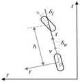
图3为车辆运动学模型示意图。车辆运动学模型简化为两自由度自行车模型,前后轮均用单轮替代。以车辆后轴中心O为原点建立车辆坐标系,沿车辆前进方向为X轴方向,垂直X轴指向车体左侧为Y轴方向。

车辆运动学模型建立原则是在保证模型简单的同时应尽可能反映车辆真实运动特性。过于严格的车辆运动学模型不利于理论推导和求解。针对地下车库工况,自行车模型采取以下假设:1)不考虑车辆在Z轴方向的运动,只考虑XY水平面的运动。2)左右侧车轮转角一致,将左右侧轮胎合并为一个轮胎。3)车辆的转向只由前轮控制。The principle of establishing the vehicle kinematics model is to reflect the real kinematic characteristics of the vehicle as much as possible while ensuring the simplicity of the model. Too strict vehicle kinematics model is not conducive to theoretical derivation and solution. For the working condition of the underground garage, the bicycle model adopts the following assumptions: 1) The movement of the vehicle in the Z-axis direction is not considered, and only the movement of the XY horizontal plane is considered. 2) The corners of the left and right wheels are the same, and the left and right tires are combined into one tire. 3) The steering of the vehicle is controlled only by the front wheels.
车辆运动学模型有两个输入:轮速传感器提供的车辆速度v和方向盘转角传感器提供的前轮转角δf。以前一时刻车辆坐标系作为参考坐标系,当前时刻车辆运动学模型表达式如下:The vehicle kinematics model has two inputs: the vehicle speed v provided by the wheel speed sensor and the front wheel angleδf provided by the steering wheel angle sensor. Taking the vehicle coordinate system at the previous moment as the reference coordinate system, the vehicle kinematic model expression at the current moment is as follows:

其中,vx和vy分别表示自动驾驶车辆在参考坐标系下X轴方向的速度、Y轴方向的速度。Among them, vx and vy represent the speed of the X-axis direction and the speed of the Y-axis direction of the autonomous vehicle in the reference coordinate system, respectively.
以上所述仅是本发明的优选实施方式,本发明的保护范围并不仅局限于上述实施例,凡属于本发明思路下的技术方案均属于本发明的保护范围。应当指出,对于本技术领域的普通技术人员来说,在不脱离本发明原理前提下的若干改进和润饰,这些改进和润饰也应视为本发明的保护范围。The above are only the preferred embodiments of the present invention, and the protection scope of the present invention is not limited to the above-mentioned embodiments, and all technical solutions under the idea of the present invention belong to the protection scope of the present invention. It should be pointed out that for those skilled in the art, some improvements and modifications without departing from the principle of the present invention should also be regarded as the protection scope of the present invention.
Claims (4)


Priority Applications (1)
| Application Number | Priority Date | Filing Date | Title |
|---|---|---|---|
| CN202010594763.9ACN111707272B (en) | 2020-06-28 | 2020-06-28 | An underground garage automatic driving laser positioning system |
Applications Claiming Priority (1)
| Application Number | Priority Date | Filing Date | Title |
|---|---|---|---|
| CN202010594763.9ACN111707272B (en) | 2020-06-28 | 2020-06-28 | An underground garage automatic driving laser positioning system |
Publications (2)
| Publication Number | Publication Date |
|---|---|
| CN111707272A CN111707272A (en) | 2020-09-25 |
| CN111707272Btrue CN111707272B (en) | 2022-10-14 |
Family
ID=72542782
Family Applications (1)
| Application Number | Title | Priority Date | Filing Date |
|---|---|---|---|
| CN202010594763.9AActiveCN111707272B (en) | 2020-06-28 | 2020-06-28 | An underground garage automatic driving laser positioning system |
Country Status (1)
| Country | Link |
|---|---|
| CN (1) | CN111707272B (en) |
Families Citing this family (16)
| Publication number | Priority date | Publication date | Assignee | Title |
|---|---|---|---|---|
| WO2022151011A1 (en)* | 2021-01-13 | 2022-07-21 | 华为技术有限公司 | Positioning method and apparatus, and vehicle |
| CN112907491B (en)* | 2021-03-18 | 2023-08-22 | 中煤科工集团上海有限公司 | Laser point cloud loop detection method and system suitable for underground roadway |
| CN113447949B (en)* | 2021-06-11 | 2022-12-09 | 天津大学 | A real-time positioning system and method based on laser radar and prior map |
| CN113740875B (en)* | 2021-08-03 | 2024-07-16 | 上海大学 | Automatic driving vehicle positioning method based on laser odometer and point cloud descriptor matching |
| CN113639782B (en)* | 2021-08-13 | 2024-10-29 | 北京地平线信息技术有限公司 | External parameter calibration method and device, equipment and medium of vehicle-mounted sensor |
| CN114018284B (en)* | 2021-10-13 | 2024-01-23 | 上海师范大学 | Wheel speed odometer correction method based on vision |
| CN113870316B (en)* | 2021-10-19 | 2023-08-15 | 青岛德智汽车科技有限公司 | Front vehicle path reconstruction method under GPS-free following scene |
| CN114296095B (en)* | 2021-12-17 | 2025-07-15 | 大卓智能科技有限公司 | Effective target extraction method, device, vehicle and medium for autonomous driving vehicle |
| CN114353799B (en)* | 2021-12-30 | 2023-09-05 | 武汉大学 | Indoor rapid global positioning method for unmanned platform equipped with multi-line lidar |
| CN114779264B (en)* | 2022-03-15 | 2025-01-03 | 南京航空航天大学 | A LiDAR positioning method based on ICP and KD tree |
| CN114820749B (en)* | 2022-04-27 | 2025-04-18 | 西安优迈智慧矿山研究院有限公司 | Unmanned vehicle underground positioning method, system, equipment and medium |
| CN115236644A (en)* | 2022-07-26 | 2022-10-25 | 广州文远知行科技有限公司 | A laser radar external parameter calibration method, device, equipment and storage medium |
| CN115494533B (en)* | 2022-09-23 | 2025-06-24 | 潍柴动力股份有限公司 | Vehicle positioning method, device, storage medium and positioning system |
| CN115655302B (en)* | 2022-12-08 | 2023-03-21 | 安徽蔚来智驾科技有限公司 | Laser odometer implementation method, computer equipment, storage medium and vehicle |
| CN117584989B (en)* | 2023-11-23 | 2024-07-19 | 昆明理工大学 | A laser radar/IMU/vehicle kinematics constraint tightly coupled SLAM system and algorithm |
| CN118031983B (en)* | 2024-04-11 | 2024-06-25 | 江苏集萃清联智控科技有限公司 | Automatic driving fusion positioning method and system |
Family Cites Families (10)
| Publication number | Priority date | Publication date | Assignee | Title |
|---|---|---|---|---|
| GB2270438B (en)* | 1992-09-08 | 1996-06-26 | Caterpillar Inc | Apparatus and method for determining the location of a vehicle |
| US7298319B2 (en)* | 2004-04-19 | 2007-11-20 | Magellan Navigation, Inc. | Automatic decorrelation and parameter tuning real-time kinematic method and apparatus |
| CN106153048A (en)* | 2016-08-11 | 2016-11-23 | 广东技术师范学院 | A kind of robot chamber inner position based on multisensor and Mapping System |
| CN107015238A (en)* | 2017-04-27 | 2017-08-04 | 睿舆自动化(上海)有限公司 | Unmanned vehicle autonomic positioning method based on three-dimensional laser radar |
| US10807236B2 (en)* | 2018-04-30 | 2020-10-20 | Beijing Jingdong Shangke Information Technology Co., Ltd. | System and method for multimodal mapping and localization |
| CN109443351B (en)* | 2019-01-02 | 2020-08-11 | 亿嘉和科技股份有限公司 | Robot three-dimensional laser positioning method in sparse environment |
| CN110261870B (en)* | 2019-04-15 | 2021-04-06 | 浙江工业大学 | A Synchronous Localization and Mapping Method for Vision-Inertial-Laser Fusion |
| CN110243358B (en)* | 2019-04-29 | 2023-01-03 | 武汉理工大学 | Multi-source fusion unmanned vehicle indoor and outdoor positioning method and system |
| CN110296698B (en)* | 2019-07-12 | 2023-04-28 | 贵州电网有限责任公司 | Unmanned aerial vehicle path planning method taking laser scanning as constraint |
| CN111337018B (en)* | 2020-05-21 | 2020-09-01 | 上海高仙自动化科技发展有限公司 | Positioning method and device, intelligent robot and computer readable storage medium |
- 2020
- 2020-06-28CNCN202010594763.9Apatent/CN111707272B/enactiveActive
Also Published As
| Publication number | Publication date |
|---|---|
| CN111707272A (en) | 2020-09-25 |
Similar Documents
| Publication | Publication Date | Title |
|---|---|---|
| CN111707272B (en) | An underground garage automatic driving laser positioning system | |
| CN112083725B (en) | Structure-shared multi-sensor fusion positioning system for automatic driving vehicle | |
| CN112083726B (en) | Park-oriented automatic driving double-filter fusion positioning system | |
| CN114526745B (en) | Drawing construction method and system for tightly coupled laser radar and inertial odometer | |
| CN113819914B (en) | A method and device for constructing a map | |
| CN113945206B (en) | Positioning method and device based on multi-sensor fusion | |
| CN112347840B (en) | Vision sensor laser radar integrated unmanned aerial vehicle positioning and image building device and method | |
| CN108955702A (en) | Based on the lane of three-dimensional laser and GPS inertial navigation system grade map creation system | |
| CN115479598A (en) | Positioning and mapping method based on multi-sensor fusion and tight coupling system | |
| CN114019552A (en) | A Bayesian Multi-sensor Error Constraint-Based Position-Location Reliability Optimization Method | |
| CN113758491B (en) | Relative positioning method and system based on multi-sensor fusion unmanned vehicle and vehicle | |
| CN101576384A (en) | Indoor movable robot real-time navigation method based on visual information correction | |
| CN111060099A (en) | Real-time positioning method for unmanned automobile | |
| US12210595B2 (en) | Systems and methods for providing and using confidence estimations for semantic labeling | |
| CN113554705B (en) | A robust lidar positioning method under changing scenarios | |
| CN116337045A (en) | High-speed map building navigation method based on karto and teb | |
| CN117906591A (en) | A multi-sensor tightly coupled SLAM algorithm | |
| CN120031968B (en) | Construction robot positioning and mapping method in long tunnel environment | |
| CN110487286A (en) | It is a kind of to project the robot pose determining method merged with laser point cloud based on point feature | |
| CN117516560A (en) | An unstructured environment map construction method and system based on semantic information | |
| CN118603077A (en) | A quadruped robot inspection map construction system and method based on multi-sensor fusion | |
| CN117706575A (en) | External rotation 3D laser radar equipment and simultaneous positioning and mapping method thereof | |
| CN111257853B (en) | Automatic driving system laser radar online calibration method based on IMU pre-integration | |
| CN119148163B (en) | Autonomous navigation method, device and medium of unmanned vehicle in unknown environment | |
| CN117782102A (en) | A fully automatic parking positioning and mapping method based on surround vision |
Legal Events
| Date | Code | Title | Description |
|---|---|---|---|
| PB01 | Publication | ||
| PB01 | Publication | ||
| SE01 | Entry into force of request for substantive examination | ||
| SE01 | Entry into force of request for substantive examination | ||
| GR01 | Patent grant | ||
| GR01 | Patent grant |