CN111703556A - A kind of cabin interior obstacle crossing trolley and working method - Google Patents
A kind of cabin interior obstacle crossing trolley and working methodDownload PDFInfo
- Publication number
- CN111703556A CN111703556ACN202010435916.5ACN202010435916ACN111703556ACN 111703556 ACN111703556 ACN 111703556ACN 202010435916 ACN202010435916 ACN 202010435916ACN 111703556 ACN111703556 ACN 111703556A
- Authority
- CN
- China
- Prior art keywords
- module
- chassis
- frame
- sliding platform
- lead screw
- Prior art date
- Legal status (The legal status is an assumption and is not a legal conclusion. Google has not performed a legal analysis and makes no representation as to the accuracy of the status listed.)
- Granted
Links
- 238000000034methodMethods0.000titleclaimsabstractdescription15
- 229910000831SteelInorganic materials0.000claimsabstractdescription29
- 239000010959steelSubstances0.000claimsabstractdescription29
- XAGFODPZIPBFFR-UHFFFAOYSA-NaluminiumChemical compound[Al]XAGFODPZIPBFFR-UHFFFAOYSA-N0.000claimsabstractdescription6
- 229910052782aluminiumInorganic materials0.000claimsabstractdescription6
- 238000013016dampingMethods0.000claimsdescription12
- 238000009434installationMethods0.000claimsdescription4
- 238000010586diagramMethods0.000description11
- 230000005389magnetismEffects0.000description3
- 238000010422paintingMethods0.000description2
- 238000005488sandblastingMethods0.000description2
- 229910000838Al alloyInorganic materials0.000description1
- 239000006096absorbing agentSubstances0.000description1
- 238000010521absorption reactionMethods0.000description1
- 230000002411adverseEffects0.000description1
- 230000009286beneficial effectEffects0.000description1
- 230000007812deficiencyEffects0.000description1
- 239000000428dustSubstances0.000description1
- 230000000694effectsEffects0.000description1
- 239000003595mistSubstances0.000description1
- 238000012986modificationMethods0.000description1
- 230000004048modificationEffects0.000description1
- 239000003973paintSubstances0.000description1
- 239000004576sandSubstances0.000description1
- 230000035939shockEffects0.000description1
Images


Classifications
- B—PERFORMING OPERATIONS; TRANSPORTING
- B63—SHIPS OR OTHER WATERBORNE VESSELS; RELATED EQUIPMENT
- B63B—SHIPS OR OTHER WATERBORNE VESSELS; EQUIPMENT FOR SHIPPING
- B63B73/00—Building or assembling vessels or marine structures, e.g. hulls or offshore platforms
- B63B73/60—Building or assembling vessels or marine structures, e.g. hulls or offshore platforms characterised by the use of specific tools or equipment; characterised by automation, e.g. use of robots
- B—PERFORMING OPERATIONS; TRANSPORTING
- B61—RAILWAYS
- B61D—BODY DETAILS OR KINDS OF RAILWAY VEHICLES
- B61D15/00—Other railway vehicles, e.g. scaffold cars; Adaptations of vehicles for use on railways
Landscapes
- Engineering & Computer Science (AREA)
- Mechanical Engineering (AREA)
- Robotics (AREA)
- Architecture (AREA)
- Structural Engineering (AREA)
- Chemical & Material Sciences (AREA)
- Combustion & Propulsion (AREA)
- Ocean & Marine Engineering (AREA)
- Transportation (AREA)
- Handcart (AREA)
Abstract
Translated fromChinese
Description
Translated fromChinese技术领域technical field
本发明涉及船舱内加工领域,特别涉及一种船舱内部越障小车及工作方法。The invention relates to the field of processing in ship cabins, in particular to an obstacle crossing trolley in the cabin and a working method.
背景技术Background technique
目前在造船业中,由于船舱内部地面都设有T型钢,一般机械在大型船舱移动困难,难以操作,由于人身高有限,为了完成船舱顶部的工序,需要搭建脚手架,完工时还需将脚手架拆除才能进行下一道工序,效率低下。另外有些工序,如喷砂、喷漆,工人在密闭的船舱内进行喷砂喷漆操作时,一些自动化机械无法使用,因此许多船舱内部的工序都是由人工完成,有时难免吸入一些砂尘和漆雾,对工人身体健康产生不良影响。因此一种能够在船舱内部实现越障且具有一定承载能力来负载如机械手这类自动化机械的小车就成了造船业的一大需求。At present, in the shipbuilding industry, since there are T-shaped steel on the ground inside the cabin, it is difficult for general machinery to move and operate in large cabins. Due to the limited height of people, in order to complete the process on the top of the cabin, scaffolding needs to be built, and the scaffolding needs to be removed when the completion is completed. In order to proceed to the next process, the efficiency is low. In addition, for some processes, such as sandblasting and painting, when workers perform sandblasting and painting operations in closed cabins, some automated machinery cannot be used. Therefore, many processes in the cabin are done manually, and sometimes it is inevitable to inhale some sand dust and paint mist. , adversely affect the health of workers. Therefore, a trolley that can overcome obstacles in the cabin and has a certain bearing capacity to load automatic machinery such as manipulators has become a big demand in the shipbuilding industry.
发明内容SUMMARY OF THE INVENTION
针对现有技术中存在的不足,本发明提供了一种船舱内部越障小车及工作方法,可以实现小车的跨越。Aiming at the deficiencies in the prior art, the present invention provides an obstacle-crossing trolley in the cabin and a working method, which can realize the crossing of the trolley.
本发明是通过以下技术手段实现上述技术目的的。The present invention achieves the above technical purpose through the following technical means.
一种船舱内部越障小车,包括滑动平台和底盘,所述滑动平台包括滑动平台框架、盖板和导向轮组,所述滑动平台框架上部安装盖板,所述滑动平台铝型材框架底部安装导向轮组;所述底盘包括底盘框架、滑台导轨模组、丝杠模组、升降支撑腿模组和驱动模组,所述滑动平台框架位于底盘框架外部,且所述底盘框架与滑动平台框架之间安装滑台导轨模组,所述丝杠模组安装在底盘框架上,所述丝杠模组用于使滑动平台框架沿滑台导轨模组移动;所述升降支撑腿模组安装在底盘框架底部,用于使底盘提升;所述驱动模组用于驱动底盘移动。An obstacle-crossing trolley inside a cabin, including a sliding platform and a chassis, the sliding platform includes a sliding platform frame, a cover plate and a guide wheel group, the upper part of the sliding platform frame is installed with a cover plate, and the bottom of the sliding platform aluminum profile frame is installed with guides Wheel set; the chassis includes a chassis frame, a sliding table guide rail module, a lead screw module, a lifting support leg module and a driving module, the sliding platform frame is located outside the chassis frame, and the chassis frame and the sliding platform frame The slide rail module is installed between them, the lead screw module is installed on the chassis frame, and the lead screw module is used to make the sliding platform frame move along the slide rail module; the lift support leg module is installed on the The bottom of the chassis frame is used to lift the chassis; the drive module is used to drive the chassis to move.
进一步,所述导向轮组包括轮座、中心轴、轴套和导向轮,所述滑动平台框架底部安装轮座,所述中心轴穿过轮座,所述中心轴两端通过轴套安装导向轮。Further, the guide wheel set includes a wheel seat, a central shaft, a shaft sleeve and a guide wheel, a wheel seat is installed at the bottom of the sliding platform frame, the central shaft passes through the wheel seat, and both ends of the central shaft are installed and guided by the shaft sleeve wheel.
进一步,所述滑台导轨模组包括滑台、滑块、导轨和限位开关;所述导轨安装在底盘框架上,所述导轨与滑块移动副连接,所述滑块上安装滑台,所述滑台与盖板连接,所述滑台与丝杠模组连接;所述底盘框架上设有限位开关,用于限制滑台移动位置。Further, the sliding table guide rail module includes a sliding table, a slider, a guide rail and a limit switch; the guide rail is installed on the chassis frame, the guide rail is connected with the sliding block moving pair, and the sliding table is installed on the sliding block, The sliding table is connected with the cover plate, and the sliding table is connected with the lead screw module; a limit switch is arranged on the chassis frame to limit the moving position of the sliding table.
进一步,所述丝杠模组包括直流电机、丝杠、弹性连接块、螺母座和第一轴承座,所述直流电机安装在底盘框架上,所述直流电机与丝杠一端连接,所述丝杠另一端通过第一轴承座与底盘框架连接,所述螺母座安装在丝杠上,所述螺母座通过弹性连接块与滑台导轨模组连接。Further, the lead screw module includes a DC motor, a lead screw, an elastic connection block, a nut seat and a first bearing seat, the DC motor is mounted on the chassis frame, the DC motor is connected to one end of the lead screw, and the screw The other end of the rod is connected with the chassis frame through a first bearing seat, the nut seat is mounted on the lead screw, and the nut seat is connected with the slide rail module through an elastic connecting block.
进一步,所述升降支撑腿模组包括电磁铁、电控升降装置和安装部件,所述电控升降装置通过安装部件与底盘框架连接,所述电控升降装置伸出端安装所述电磁铁。Further, the lifting support leg module includes an electromagnet, an electronically controlled lifting device and an installation component, the electronically controlled lifting device is connected to the chassis frame through the installation component, and the electromagnet is installed at the protruding end of the electronically controlled lifting device.
进一步,所述驱动模组包括步进电机、第二轴承座和车轮,所述第二轴承座安装在底盘框架上,所述车轮支撑在第二轴承座上,所述步进电机用于驱动车轮;Further, the drive module includes a stepper motor, a second bearing seat and a wheel, the second bearing seat is mounted on the chassis frame, the wheel is supported on the second bearing seat, and the stepper motor is used for driving wheel;
进一步,还包括述减震模组,所述减震模组包括顶板、减震装置和底板,所述减震装置位于顶板与底板之间,所述底板安装在底盘框架上,所述顶板上安装驱动模组。Further, it also includes the shock-absorbing module, the shock-absorbing module includes a top plate, a shock-absorbing device and a bottom plate, the shock-absorbing device is located between the top plate and the bottom plate, the bottom plate is mounted on the chassis frame, and the top plate Install the driver module.
一种的船舱内部越障小车的工作方法,包括如下步骤:A working method of an obstacle-crossing trolley in a cabin, comprising the following steps:
通过电控升降装置使底盘抬起,通过电磁铁通电吸紧底盘底部T型钢;The chassis is lifted by the electronically controlled lifting device, and the T-shaped steel at the bottom of the chassis is tightened by energizing the electromagnet;
通过丝杠模组正转使滑动平台平移;The sliding platform is translated by the forward rotation of the screw module;
通过电控升降装置使底盘下降,所述滑动平台的导向轮组放置在另一对T型钢上;The chassis is lowered by an electronically controlled lifting device, and the guide wheel set of the sliding platform is placed on another pair of T-beams;
电磁铁断电后,通过丝杠模组反转使底盘移动到另一对T型钢上。After the electromagnet is powered off, the chassis is moved to another pair of T-beams by reversing the lead screw module.
本发明的有益效果在于:The beneficial effects of the present invention are:
本发明所述的船舱内部越障小车及工作方法,在滑动平台框架底部四角对称布置四组导向轮组,每两个导向轮为一组,呈“工”字型,其间距比船舱内部T型钢略宽,且间距可根据不同T型钢宽度调整,以便在船舱内部T型钢上限位并沿T型钢行走。底座滑台与小车滑动平台相连,通过丝杠模组带动滑台在导轨上左右移动,以实现小车滑动平台水平跨越梯形钢之间的凹槽,并进一步带动小车底盘跨越凹槽。两对升降支撑腿对称布置在铝型材框架底部,在小车滑动平台越障时紧吸T型钢,防止小车倾覆。一对驱动模组对称布置在两对升降支撑腿之间,为小车在T型钢上行驶提供动力。两个减震模组分别布置在驱动模组之上,减小了小车在不平整的T型钢上行驶时小车受到的冲力,保证小车滑动平台的稳定。In the cabin interior obstacle trolley and its working method according to the present invention, four sets of guide wheel sets are symmetrically arranged at the four corners of the bottom of the sliding platform frame, and each two guide wheels is a set, which is in the shape of "I", and its spacing is larger than that of the interior of the cabin. The section steel is slightly wider, and the spacing can be adjusted according to different T-section steel widths, so that the T-section steel can be positioned at the upper limit and walk along the T-section steel inside the cabin. The base sliding table is connected with the trolley sliding platform, and the lead screw module drives the sliding table to move left and right on the guide rail, so that the trolley sliding platform horizontally spans the grooves between the trapezoidal steels, and further drives the trolley chassis to span the grooves. Two pairs of lifting support legs are symmetrically arranged at the bottom of the aluminum profile frame, and the T-shaped steel is tightly sucked when the trolley sliding platform crosses obstacles to prevent the trolley from overturning. A pair of drive modules are symmetrically arranged between the two pairs of lifting support legs to provide power for the trolley to travel on the T-shaped steel. The two damping modules are respectively arranged on the driving module, which reduces the impact on the trolley when the trolley runs on the uneven T-shaped steel, and ensures the stability of the sliding platform of the trolley.
附图说明Description of drawings
图1为本发明所述的船舱内部越障小车结构示意图。FIG. 1 is a schematic structural diagram of the obstacle-crossing trolley in the cabin according to the present invention.
图2为本发明所述的导向轮组构造示意图;Figure 2 is a schematic structural diagram of the guide wheel set according to the present invention;
图3为本发明所述的滑台导轨模组和底盘铝型材框架构造示意图;3 is a schematic structural diagram of the slide rail module and the chassis aluminum profile frame according to the present invention;
图4为本发明所述的丝杠模组构造示意图;4 is a schematic structural diagram of the lead screw module according to the present invention;
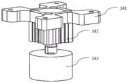
图5为本发明所述的升降支撑腿模组构造示意图;5 is a schematic structural diagram of the lifting and supporting leg module according to the present invention;
图6为本发明所述的减震模组构造示意图;6 is a schematic structural diagram of the damping module according to the present invention;
图7为本发明所述的驱动模组构造示意图;7 is a schematic structural diagram of the drive module according to the present invention;
图8为工作状态一的示意图;Fig. 8 is the schematic diagram of working state one;
图9为工作状态二的示意图;Fig. 9 is the schematic diagram of working state two;
图10为工作状态三的示意图;Fig. 10 is the schematic diagram of working state three;
图11为工作状态四的示意图。FIG. 11 is a schematic diagram of working state four.
图中:In the picture:
1-滑动平台;110-滑动平台框架;120-盖板;130-导向轮组;131-轮座;132-中心轴;133-轴套;134-导向轮;2-底盘;210-底盘框架;220-滑台导轨模组;221-滑台;222-滑块;223-导轨;224-限位开关;230-丝杠模组;231-直流电机;232-丝杠;233-弹性连接块;234-螺母座;235-第一轴承座;240-升降支撑腿模组;241-电磁铁;242-电控升降装置;243-安装部件;250-减震模组;251-顶板;252-减震装置;253-底板;260-驱动模组;261-步进电机;262-第二轴承座;263-车轮。1-Sliding platform; 110-Sliding platform frame; 120-Cover plate; 130-Guide wheel set; 131-Wheel seat; 132-Central shaft; 133-Sleeve; 134-Guide wheel; 2-Chassis; ;220-slide rail module; 221-slide; 222-slider; 223-rail; 224-limit switch; 230-screw module; 231-DC motor; 232-screw; 233-elastic connection block; 234-nut seat; 235-first bearing seat; 240-lifting support leg module; 241-electromagnet; 242-electrically controlled lifting device; 243-installation parts; 250-damping module; 251-top plate; 252-shock absorber; 253-base plate; 260-drive module; 261-stepper motor; 262-second bearing seat; 263-wheel.
具体实施方式Detailed ways
下面结合附图以及具体实施例对本发明作进一步的说明,但本发明的保护范围并不限于此。The present invention will be further described below with reference to the accompanying drawings and specific embodiments, but the protection scope of the present invention is not limited thereto.
如图1所示,本发明所述的船舱内部越障小车,包括滑动平台1和底盘2,所述滑动平台1包括滑动平台框架110、盖板120和导向轮组130,所述滑动平台框架110上部安装盖板120,所述滑动平台铝型材框架110底部安装导向轮组130;如图2所示,所述导向轮组130包括轮座131、中心轴132、轴套133和导向轮134,所述滑动平台框架110底部安装轮座131,所述中心轴132穿过轮座131,所述中心轴132两端通过轴套133安装导向轮134。所述导向轮134为单边轮,且中心轴132两端的单边轮对称布置。,两个导向轮134为一组,其间距比船舱内部T型钢略宽,且间距可根据不同T型钢宽度调整,以便在船舱内部T型钢上限位并沿T型钢行走。As shown in Figure 1, the cabin interior obstacle trolley according to the present invention includes a
如图3所示,所述底盘包括底盘框架210、滑台导轨模组220、丝杠模组230、升降支撑腿模组240和驱动模组260,所述滑动平台框架110位于底盘框架210外部,且所述底盘框架210与滑动平台框架110之间安装滑台导轨模组220,所述丝杠模组230安装在底盘框架210上,所述丝杠模组230用于使滑动平台框架110沿滑台导轨模组220移动;所述升降支撑腿模组240安装在底盘框架210底部,用于使底盘2提升;所述驱动模组260用于驱动底盘2移动。所述滑台导轨模组220包括滑台221、滑块222、导轨223和限位开关224;所述导轨223安装在底盘框架210上,所述导轨223与滑块222移动副连接,所述滑块222上安装滑台221,所述滑台221与盖板120连接,所述滑台221与丝杠模组230连接;所述底盘框架210上设有限位开关224,用于限制滑台221移动位置。通过丝杠模组230正反转带动滑台221水平左右移动。所述滑动平台框架110和底盘框架210结构为框架式,由铝合金型材搭建而成。As shown in FIG. 3 , the chassis includes a
如图4所示,所述丝杠模组230包括直流电机231、丝杠232、弹性连接块233、螺母座234和第一轴承座235,所述直流电机231安装在底盘框架210上,所述直流电机231与丝杠232一端连接,所述丝杠232另一端通过第一轴承座235与底盘框架210连接,所述螺母座234安装在丝杠232上,所述螺母座234通过弹性连接块233与滑台导轨模组220连接。所述直流电机可控制正/反转,带动丝杠顺/逆时针转动,而带动上部滑台和与滑台相连的滑动平台水平移动,实现越障。由于T型钢表面会有不平整之处,当小车在T型钢上行走时会有振动,弹性连接块会有一定的减震效果,防止上部负载设备的滑动平台振动过大。As shown in FIG. 4 , the
如图5所示,所述升降支撑腿模组240包括电磁铁241、电控升降装置242和安装部件243,所述电控升降装置242通过安装部件243与底盘框架210连接,所述电控升降装置242伸出端安装所述电磁铁241。由所述电控升降装置带动电磁铁放下和收回。当需要越障时,电磁铁被放下,将滑动平台抬起0.5~0.8mm,并给电磁铁通电产生磁性,紧吸在T型钢上,等丝杠模组将滑动平台送至另一平行处的T型钢时,将电磁铁收回,滑动平台被放下,电磁铁断电失去磁性,此时丝杠模组电机驱动丝杠,再将底盘移至另一T型钢上,实现小车的越障。As shown in FIG. 5 , the lifting and supporting
如图7所示,所述驱动模组260包括步进电机261、第二轴承座262和车轮263,所述第二轴承座262安装在底盘框架210上,所述车轮263支撑在第二轴承座262上,所述步进电机261用于驱动车轮263;As shown in FIG. 7 , the
如图6所示,还包括减震模组250,所述减震模组250包括顶板251、减震装置252和底板253,所述减震装置252位于顶板251与底板253之间,所述底板253安装在底盘框架210上,所述顶板251上安装驱动模组260。可有效较少驱动模组由于T型钢表面不平整而产生的振动对减震模组的上部小车结构的影响。As shown in FIG. 6 , it also includes a damping
在本发明实施例中,所述直流电机、电控升降装置、电磁铁、限位开关、步进电机均与一控制器电性连接,对于控制器对各器件的顺序协调控制,可通过现有的控制电路、方法完成,至于控制器控制直流电机带动丝杠转动、控制步进电机以使小车行走均为现有技术,在此便不过多赘述。In the embodiment of the present invention, the DC motor, the electronically controlled lifting device, the electromagnet, the limit switch, and the stepping motor are all electrically connected to a controller. Some control circuits and methods are completed. As for the controller controlling the DC motor to drive the lead screw to rotate, and controlling the stepper motor to make the trolley move, they are all in the prior art, and will not be described here.
本发明所述的船舱内部越障小车的工作方法,按以下步骤进行:如图8所示当需要越过舱底沟槽将小车送至另一T型钢上时,电磁铁241被放下,通过底盘框架210将小车滑动平台1抬起,使导向轮134高过T型钢,并通电使电磁铁241产生磁性,紧吸在T型钢上;丝杠模组中的电机驱动丝杠正转,将与滑台221相连的滑动平台1水平向右移动,直至限位开关的滑片到达右端的限位开关处,过程如图9所示;电磁铁241被收回,滑动平台1被放置到另一对T型钢上,如图10所示;电磁铁241断电,丝杠模组的电机驱动丝杠反转,将小车底盘2带到另一对T型钢上,如图11所示。至此,整个小车的越障完成。The working method of the obstacle-crossing trolley in the cabin according to the present invention is carried out according to the following steps: as shown in FIG. 8 , when the trolley needs to be sent to another T-shaped steel over the bilge groove, the
所述实施例为本发明的优选的实施方式,但本发明并不限于上述实施方式,在不背离本发明的实质内容的情况下,本领域技术人员能够做出的任何显而易见的改进、替换或变型均属于本发明的保护范围。The embodiments are preferred embodiments of the present invention, but the present invention is not limited to the above-mentioned embodiments, and any obvious improvement, replacement or All modifications belong to the protection scope of the present invention.
Claims (8)
Translated fromChinesePriority Applications (1)
| Application Number | Priority Date | Filing Date | Title |
|---|---|---|---|
| CN202010435916.5ACN111703556B (en) | 2020-05-21 | 2020-05-21 | A kind of cabin interior obstacle crossing trolley and working method |
Applications Claiming Priority (1)
| Application Number | Priority Date | Filing Date | Title |
|---|---|---|---|
| CN202010435916.5ACN111703556B (en) | 2020-05-21 | 2020-05-21 | A kind of cabin interior obstacle crossing trolley and working method |
Publications (2)
| Publication Number | Publication Date |
|---|---|
| CN111703556Atrue CN111703556A (en) | 2020-09-25 |
| CN111703556B CN111703556B (en) | 2022-02-15 |
Family
ID=72537983
Family Applications (1)
| Application Number | Title | Priority Date | Filing Date |
|---|---|---|---|
| CN202010435916.5AActiveCN111703556B (en) | 2020-05-21 | 2020-05-21 | A kind of cabin interior obstacle crossing trolley and working method |
Country Status (1)
| Country | Link |
|---|---|
| CN (1) | CN111703556B (en) |
Citations (5)
| Publication number | Priority date | Publication date | Assignee | Title |
|---|---|---|---|---|
| CN2673583Y (en)* | 2004-02-16 | 2005-01-26 | 中国科学技术大学 | High power passive obstacle crossing robot |
| CN203032789U (en)* | 2012-12-12 | 2013-07-03 | 西安理工大学 | Self-leveling five-wheel survey vehicle |
| CN204184489U (en)* | 2014-08-04 | 2015-03-04 | 江苏大学 | A kind of chassis structure of Small Ground Mobile Robot |
| CN107323551A (en)* | 2017-06-26 | 2017-11-07 | 徐州乐泰机电科技有限公司 | A kind of wheel leg type obstacle-surmounting travelling gear |
| CN209683365U (en)* | 2019-01-16 | 2019-11-26 | 中铁上海工程局集团有限公司 | A kind of longitudinal movement trolley of changeable walking system |
- 2020
- 2020-05-21CNCN202010435916.5Apatent/CN111703556B/enactiveActive
Patent Citations (5)
| Publication number | Priority date | Publication date | Assignee | Title |
|---|---|---|---|---|
| CN2673583Y (en)* | 2004-02-16 | 2005-01-26 | 中国科学技术大学 | High power passive obstacle crossing robot |
| CN203032789U (en)* | 2012-12-12 | 2013-07-03 | 西安理工大学 | Self-leveling five-wheel survey vehicle |
| CN204184489U (en)* | 2014-08-04 | 2015-03-04 | 江苏大学 | A kind of chassis structure of Small Ground Mobile Robot |
| CN107323551A (en)* | 2017-06-26 | 2017-11-07 | 徐州乐泰机电科技有限公司 | A kind of wheel leg type obstacle-surmounting travelling gear |
| CN209683365U (en)* | 2019-01-16 | 2019-11-26 | 中铁上海工程局集团有限公司 | A kind of longitudinal movement trolley of changeable walking system |
Also Published As
| Publication number | Publication date |
|---|---|
| CN111703556B (en) | 2022-02-15 |
Similar Documents
| Publication | Publication Date | Title |
|---|---|---|
| CN103962781B (en) | Box type rod piece group founds hold-down mechanism on machine | |
| US20210269110A1 (en) | Method and Apparatus for Replacement of Windshields for Recreational Vehicles, Charter Buses and Large Trucks | |
| CN209193303U (en) | A construction hoist with a changeable track | |
| CN207955718U (en) | The electric platforms formula device of server cabinet built-in device is installed | |
| CN214418112U (en) | A workpiece mounting device | |
| CN104097061B (en) | Tank container General assembling table | |
| CN111703556A (en) | A kind of cabin interior obstacle crossing trolley and working method | |
| CN203209974U (en) | General assembling table for tank container | |
| CN100476043C (en) | Aluminum electrolyzer overhaul transportation system and method | |
| CN220886655U (en) | Electromagnetic chuck electric single-beam crane | |
| CN221233835U (en) | Thrust wheel bracket convenient to installation | |
| CN105292981B (en) | Passage jacking table apparatus | |
| CN218365467U (en) | Chiseling equipment provided with multi-direction adjustment and used for prefabricated part | |
| CN111846030B (en) | Shear fork truck steering mechanism assembly fixture | |
| CN107500186B (en) | A 1000KV GIS equipment maintenance platform | |
| CN216709313U (en) | Bogie replacing equipment | |
| CN217394520U (en) | Concrete surface grinding device | |
| CN214266208U (en) | Wall roughening machine | |
| CN214456513U (en) | Crane rail mounting vehicle | |
| CN111906510B (en) | Assembling lifting mechanism of electric locomotive driving unit | |
| CN111285040B (en) | A relining manipulator bridge structure | |
| CN220498766U (en) | Automatic grinding machine for steel ingot | |
| CN221027299U (en) | Ground rail type lifting frame for paint spraying equipment | |
| CN216803035U (en) | Ship bottom shot blasting machine moving device | |
| CN219117070U (en) | Dedicated jacking equipment of electromechanical installation |
Legal Events
| Date | Code | Title | Description |
|---|---|---|---|
| PB01 | Publication | ||
| PB01 | Publication | ||
| SE01 | Entry into force of request for substantive examination | ||
| SE01 | Entry into force of request for substantive examination | ||
| GR01 | Patent grant | ||
| GR01 | Patent grant |