CN111678514A - A vehicle autonomous navigation method based on carrier motion condition constraints and single-axis rotation modulation - Google Patents
A vehicle autonomous navigation method based on carrier motion condition constraints and single-axis rotation modulationDownload PDFInfo
- Publication number
- CN111678514A CN111678514ACN202010520820.9ACN202010520820ACN111678514ACN 111678514 ACN111678514 ACN 111678514ACN 202010520820 ACN202010520820 ACN 202010520820ACN 111678514 ACN111678514 ACN 111678514A
- Authority
- CN
- China
- Prior art keywords
- error
- coordinate system
- carrier
- axis
- velocity
- Prior art date
- Legal status (The legal status is an assumption and is not a legal conclusion. Google has not performed a legal analysis and makes no representation as to the accuracy of the status listed.)
- Granted
Links
Images

Classifications
- G—PHYSICS
- G01—MEASURING; TESTING
- G01C—MEASURING DISTANCES, LEVELS OR BEARINGS; SURVEYING; NAVIGATION; GYROSCOPIC INSTRUMENTS; PHOTOGRAMMETRY OR VIDEOGRAMMETRY
- G01C21/00—Navigation; Navigational instruments not provided for in groups G01C1/00 - G01C19/00
- G01C21/10—Navigation; Navigational instruments not provided for in groups G01C1/00 - G01C19/00 by using measurements of speed or acceleration
- G01C21/12—Navigation; Navigational instruments not provided for in groups G01C1/00 - G01C19/00 by using measurements of speed or acceleration executed aboard the object being navigated; Dead reckoning
- G01C21/16—Navigation; Navigational instruments not provided for in groups G01C1/00 - G01C19/00 by using measurements of speed or acceleration executed aboard the object being navigated; Dead reckoning by integrating acceleration or speed, i.e. inertial navigation
- G01C21/18—Stabilised platforms, e.g. by gyroscope
Landscapes
- Engineering & Computer Science (AREA)
- Radar, Positioning & Navigation (AREA)
- Remote Sensing (AREA)
- Automation & Control Theory (AREA)
- Physics & Mathematics (AREA)
- General Physics & Mathematics (AREA)
- Navigation (AREA)
Abstract
Translated fromChinese
Description
Translated fromChinese技术领域technical field
本发明属于导航技术领域,具体涉及一种基于载体运动条件约束和单轴旋转调制的车载自主导航方法。The invention belongs to the technical field of navigation, and in particular relates to a vehicle autonomous navigation method based on carrier motion condition constraints and single-axis rotation modulation.
背景技术Background technique
随着智能交通技术的迅猛发展,车辆导航系统(LVNS)成为研究热点,被广泛应用于多种应用场景,包括车队管理系统、碰撞规避制动及车辆跟踪系统等。卫星/惯性组合导航系统因其互补性,在车辆导航系统中广泛应用。但由于城市建筑、隧道、树木等易造成卫星信号遮挡,期间导航解算仅基于惯性导航系统完成,导致导航误差迅速累积并发散。这种情况在基于MEMS IMU(Micro ElectroMechanical System Inertial Measurement Unit,微机电系统惯性测量单元)的惯性系统中尤为显著。MEMS传感器所具有的高噪声水平和零偏不稳定性使其自主导航模式面临极大的挑战,位置误差在较短的时间内可累计至数千米。如何提高惯性系统自主导航精度,延长其自主导航时间是提高车载导航系统可靠性、鲁棒性和精度的关键。With the rapid development of intelligent transportation technology, vehicle navigation systems (LVNS) have become a research hotspot and are widely used in various application scenarios, including fleet management systems, collision avoidance braking, and vehicle tracking systems. Satellite/inertial integrated navigation systems are widely used in vehicle navigation systems because of their complementarity. However, since urban buildings, tunnels, trees, etc. are easy to cause satellite signal occlusion, the navigation solution is only completed based on the inertial navigation system during the period, resulting in the rapid accumulation and dispersion of navigation errors. This situation is particularly significant in inertial systems based on MEMS IMUs (Micro ElectroMechanical System Inertial Measurement Unit). The high noise level and bias instability of MEMS sensors make the autonomous navigation mode extremely challenging, and position errors can accumulate to thousands of meters in a relatively short period of time. How to improve the autonomous navigation accuracy of inertial system and prolong its autonomous navigation time is the key to improve the reliability, robustness and accuracy of vehicle navigation system.
在没有其他传感器辅助的情况下,车辆运动约束条件常用于限制惯性导航系统误差累积。在车辆静止状态下时可使用零速修正(ZUPT)与零角速度修正(ZARU)来抑制误差累积,但这将限制车辆的机动性。非完整性约束条件(NHC)指在车辆正常运行时,沿竖直方向和横向方向的速度分量近似为零。利用此先验条件,可以在一定程度上改善车辆在运动状态下的惯性导航误差累积。但此方法的主要缺陷在于:第一,观测量中缺少车辆前向行驶速度;第二,惯性系统误差可观测度与载体机动性高度相关,车辆正常行驶时机动性较弱,从而会降低部分惯性误差的估计精度。因此,NHC仅能在较短的时期内抑制导航误差。Vehicle motion constraints are often used to limit INS error accumulation without the aid of other sensors. Zero velocity correction (ZUPT) and zero angular velocity correction (ZARU) can be used to suppress error accumulation when the vehicle is stationary, but this will limit the maneuverability of the vehicle. The non-integrity constraint (NHC) means that when the vehicle is running normally, the velocity components along the vertical and lateral directions are approximately zero. Using this prior condition, the accumulation of inertial navigation errors in the moving state of the vehicle can be improved to a certain extent. However, the main drawbacks of this method are: first, the vehicle's forward speed is lacking in the observation; second, the observability of the inertial system error is highly related to the mobility of the carrier, and the mobility of the vehicle is weak during normal driving, which will reduce part of the Estimation accuracy of inertial error. Therefore, NHC can suppress navigation errors only for a short period of time.
发明内容SUMMARY OF THE INVENTION
本发明的目的是克服现有技术基于惯性系统的车载自主导航方法研究的不足,提供一种基于载体运动条件约束和单轴旋转调制的车载自主导航方法。将MEMS IMU安装在车轮中心,使其随着车辆行驶而旋转。基于旋转IMU的输出计算载体前行速度,并联合非完整性约束条件(NHC),形成载体三维速度观测量;利用改进的捷联惯性导航解算方程,基于旋转IMU的惯性输出,解算载体位置、速度与姿态信息。基于扩展型卡尔曼滤波,将载体三维速度作为观测量,实现对惯性系统误差的在线估计,并对载体位置、速度与姿态误差进行修正,进而提高车载自主导航精度。The purpose of the present invention is to overcome the deficiencies in the research on the vehicle-mounted autonomous navigation method based on the inertial system in the prior art, and provide a vehicle-mounted autonomous navigation method based on carrier motion condition constraints and single-axis rotation modulation. Mount the MEMS IMU in the center of the wheel so that it rotates as the vehicle travels. The forward speed of the carrier is calculated based on the output of the rotating IMU, and combined with the non-integrity constraint (NHC) to form the three-dimensional velocity observation of the carrier; the improved strapdown inertial navigation solution equation is used to solve the carrier based on the inertial output of the rotating IMU. Position, velocity and attitude information. Based on the extended Kalman filter, the three-dimensional velocity of the carrier is taken as the observation quantity, the online estimation of the inertial system error is realized, and the position, velocity and attitude errors of the carrier are corrected, so as to improve the accuracy of vehicle autonomous navigation.
本发明所提出的技术问题是这样解决的:The technical problem proposed by the present invention is solved like this:
一种基于载体运动条件约束和单轴旋转调制的车载自主导航方法,包括以下步骤:A vehicle autonomous navigation method based on carrier motion condition constraints and single-axis rotation modulation, comprising the following steps:
步骤1.基于旋转IMU的虚拟里程计计算载体前行速度和车轮旋转角度;Step 1. Calculate the forward speed of the carrier and the rotation angle of the wheel based on the virtual odometer of the rotating IMU;
将IMU安装在车轮中心,使IMU随着载体运动而旋转;o-xsyszs代表传感器坐标系,o-xbybzb代表载体坐标系;当载体运动时,o-xsyszs绕xs轴旋转;在传感器坐标系中,IMU实际输出的比力


其中,


ys轴和zs轴加速度计的实际输出


其中,g为当地重力加速度,


传感器坐标系中xs轴陀螺仪实际输出

其中,ds为xs轴陀螺仪输出误差;
ys轴的加速度计实际输出


其中,
基于扩展型卡尔曼滤波,通过IMU输出来计算载体沿yb轴速度
系统状态量xo和系统方程分别由式(9)和(10)表示:The system state quantity xo and the system equation are represented by equations (9) and (10), respectively:


其中,


经过线性化之后的系统观测模型由式(11)表示:The system observation model after linearization is expressed by equation (11):
zo=Hoxo+v (11)zo = Ho xo +v (11)
其中,


步骤2.建立载体自主导航误差方程Step 2. Establish carrier autonomous navigation error equation
将比力fs和旋转角速度


其中,
基于转换至载体坐标系的比力和角速率,利用传统捷联导航解算方程解算出载体位置rn、速度vn与姿态信息
(1)姿态误差方程(1) Attitude error equation
捷联惯性导航中姿态更新方程为:The attitude update equation in strapdown inertial navigation is:

其中,


根据姿态误差定义

在小失准角的情况下,通过对式(14)进行扰动分析推导得出姿态误差方程:In the case of a small misalignment angle, the attitude error equation is derived by performing disturbance analysis on equation (14):

其中,δrn为位置误差矢量,


其中,M为载体所在位置子午圈的曲率半径,N为载体所在位置卯酉圈的曲率半径,ωie为地球自转角速度值,h为载体高度,
(2)速度误差方程(2) Speed error equation
导航坐标系下速度更新方程表示为:The velocity update equation in the navigation coordinate system is expressed as:

其中,


根据速度误差定义


其中,


其中,vE、vN和vU分别表示东向、北向和天向的载体的速度值,fE、fN和fU分别表示东向、北向和天向的载体的比力值,γ表示随载体维度和高度变化的当地重力加速度;Among them, vE , vN and vU represent the velocity values of the carrier in the east, north and sky directions, respectively, fE , fN and fU represent the specific force values of the east, north and sky directions, respectively, γ represents the local gravitational acceleration that varies with the dimension and height of the carrier;
(3)位置误差方程(3) Position error equation
捷联惯性导航中位置更新方程:Position update equation in strapdown inertial navigation:

其中,

通过对式(18)进行扰动分析得出位置误差方程:The position error equation is obtained by perturbation analysis of equation (18):

其中,


(4)MEMS IMU传感器误差方程(4) MEMS IMU sensor error equation
MEMS加速度计和陀螺仪误差建模为一阶高斯马可夫随机过程,如式(20)所示:The MEMS accelerometer and gyroscope errors are modeled as a first-order Gaussian Markov random process, as shown in equation (20):

其中,
加速度计和陀螺仪误差方程:Accelerometer and gyroscope error equations:


其中,


步骤3.载体运动约束条件下的自主导航模型建立Step 3. Establishment of autonomous navigation model under carrier motion constraints
利用扩展型卡尔曼滤波计算出惯性系统的位置误差、速度误差、姿态误差以及加速度计和陀螺仪误差;The position error, velocity error, attitude error, and accelerometer and gyroscope errors of the inertial system are calculated by the extended Kalman filter;
首先建立系统状态方程;根据车载惯性导航系统特性,选取位置误差、速度误差、姿态误差、加速度计和陀螺仪误差组成15维状态量,如式(23)所示:Firstly, the system state equation is established; according to the characteristics of the vehicle inertial navigation system, the position error, velocity error, attitude error, accelerometer and gyroscope errors are selected to form a 15-dimensional state quantity, as shown in formula (23):
x==[δrn δvn εn γb db]T (23)x==[δrn δvn εn γb db ]T (23)
根据式(15)、(17)、(19)、(21)和(22),系统状态方程由式(24)表示:According to equations (15), (17), (19), (21) and (22), the system state equation is represented by equation (24):

其中,


其次建立系统观测方程;载体坐标系o-xbybzb下的速度矢量表示为:

其中,vb是vn的斜对称矩阵,表示载体坐标系下的速度;
系统观测量方程为:The system observation equation is:
z=Hx+v (26)z=Hx+v (26)
其中,z=δvb,
基于系统状态方程(24)和系统观测量方程(26),利用扩展型卡尔曼滤波计算得到位置误差、速度误差和姿态误差,来修正惯性导航系统中的位置、速度和姿态状态量,即可提高载体自主导航的精度。Based on the system state equation (24) and the system observation quantity equation (26), the position error, velocity error and attitude error are calculated by using the extended Kalman filter to correct the position, velocity and attitude state quantities in the inertial navigation system. Improve the accuracy of the carrier's autonomous navigation.
本发明的有益效果是:The beneficial effects of the present invention are:
(1)本发明利用安装在车轮IMU输出与车轮转动的关系,推导出载体前行速度,并结合载体本身运动特性,获取载体坐标系下的三维速度观测量,并用以约束惯性导航误差累积,有效解决了使用单个IMU导航时由于缺少外部观测量而导致导航误差迅速累积发散的问题。(1) The present invention utilizes the relationship between the output of the IMU installed on the wheel and the rotation of the wheel to derive the forward speed of the carrier, and combines the motion characteristics of the carrier itself to obtain the three-dimensional velocity observation under the carrier coordinate system, and to restrain the accumulation of inertial navigation errors, It effectively solves the problem of rapid accumulation and divergence of navigation errors due to the lack of external observations when navigating with a single IMU.
(2)由于IMU随着车轮转动而旋转,本发明有效的提高了惯性系统中误差的可观测性,特别是方位角方向的陀螺仪误差,有效的抑制了方位角误差的累积,从而提高了导航的精度。(2) Since the IMU rotates with the rotation of the wheel, the present invention effectively improves the observability of errors in the inertial system, especially the gyroscope errors in the azimuth direction, effectively suppresses the accumulation of azimuth errors, and improves the accuracy of navigation.
(3)本发明除了使用一个低成本的MEMS IMU以外,不使用额外的硬件和设备,方法可行,简单、经济,具有较强的工程应用潜力。(3) In addition to using a low-cost MEMS IMU, the present invention does not use additional hardware and equipment, the method is feasible, simple and economical, and has strong engineering application potential.
附图说明Description of drawings
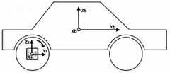
图1为安装在车轮中心IMU旋转示意图;Figure 1 is a schematic diagram of the rotation of the IMU installed in the center of the wheel;
图2为基于旋转IMU的虚拟里程计原理图;Figure 2 is a schematic diagram of a virtual odometer based on a rotating IMU;
图3为本发明所述基于载体运动条件约束和单轴旋转调制的车载自主导航方法算法流程示意图。FIG. 3 is a schematic flowchart of the algorithm of the vehicle autonomous navigation method based on carrier motion condition constraints and single-axis rotation modulation according to the present invention.
具体实施方式Detailed ways
下面结合附图和实施例对本发明进行进一步的说明。The present invention will be further described below with reference to the accompanying drawings and embodiments.
安装在车轮中心IMU旋转示意图如图1所示,基于旋转IMU的虚拟里程计原理图如图2所示。The schematic diagram of the rotation of the IMU installed in the center of the wheel is shown in Figure 1, and the schematic diagram of the virtual odometer based on the rotating IMU is shown in Figure 2.
本实施例提供一种基于载体运动条件约束和单轴旋转调制的车载自主导航方法,包括以下步骤:This embodiment provides a vehicle-mounted autonomous navigation method based on carrier motion condition constraints and single-axis rotation modulation, including the following steps:
步骤1.基于旋转IMU的虚拟里程计计算载体前行速度和车轮旋转角度;Step 1. Calculate the forward speed of the carrier and the rotation angle of the wheel based on the virtual odometer of the rotating IMU;
将IMU安装在车轮中心,使IMU随着载体运动而旋转;o-xsyszs代表传感器坐标系,o-xbybzb代表载体坐标系,其中yb轴指向车辆前方,zb轴垂直yb轴指向上方,xb与其余两轴满足右手定则指向车辆右方;o-xsyszs坐标系与o-xbybzb坐标系初始时刻对齐,当载体运动时,o-xsyszs绕xs轴旋转,;在传感器坐标系中,IMU实际输出的比力


其中,


根据式(1),ys轴和zs轴加速度计的实际输出


其中,g为当地重力加速度,


根据式(2),传感器坐标系中xs轴陀螺仪实际输出

其中,

由于运动载体通常行驶在相对水平的路面,并且保持加速度相对较小,因此ys轴的加速度计实际输出


其中,
由式(6)和(7)可以看出,车轮旋转将重力投影至传感器坐标系的ys轴和zs轴,投影量与车轮旋转角度分别成正弦和余弦的关系;由式(8)可以看出,xs轴的陀螺仪输出可以近似为车轮旋转角速率;因此载体沿yb轴速度
在将系统线性化之后,系统状态量xo和系统方程可分别由式(9)和(10)表示:After linearizing the system, the system state quantity xo and the system equation can be expressed by equations (9) and (10), respectively:


其中,


基于式(6),(7)和(8),经过线性化之后的系统观测模型可由式(11)表示:Based on equations (6), (7) and (8), the linearized system observation model can be expressed by equation (11):
zo=Hoxo+v (11)zo = Ho xo +v (11)
其中,


步骤2.建立载体自主导航误差方程Step 2. Establish carrier autonomous navigation error equation
安装在车轮的IMU随着载体运动而产生旋转,因此可看做单轴旋转调制惯性系统,其结算流程与传动捷联惯导系统的不同之处在于,单轴旋转系统中IMU输出是在传感器坐标系o-xsyszs,因此需要先将比力fs和旋转角速度


其中,


由式(12)和(13)可知,IMU旋转主要调制了加速度计和陀螺仪误差,但并未改变捷联惯性系统中姿态误差、速度误差和位置误差之间的关系,因此捷联惯性系统中姿态误差、速度误差以及位置误差方程仍然成立;It can be seen from equations (12) and (13) that the IMU rotation mainly modulates the accelerometer and gyroscope errors, but does not change the relationship between the attitude error, velocity error and position error in the strapdown inertial system, so the strapdown inertial system Attitude error, velocity error and position error equations are still established;
(1)姿态误差方程(1) Attitude error equation
捷联惯性导航中姿态更新方程为:The attitude update equation in strapdown inertial navigation is:

其中,


根据姿态误差定义

在小失准角的情况下,通过对式(14)进行扰动分析推导得出姿态误差方程:In the case of a small misalignment angle, the attitude error equation is derived by performing disturbance analysis on equation (14):

其中,δrn为位置误差矢量,


其中,M为载体所在位置子午圈(沿南北方向)的曲率半径,N为载体所在位置卯酉圈(沿东西方向)的曲率半径,ωie为地球自转角速度值,h为载体高度,
(2)速度误差方程(2) Speed error equation
根据捷联惯性导航中的比力方程,导航坐标系下速度更新方程可表示为:According to the specific force equation in strapdown inertial navigation, the velocity update equation in the navigation coordinate system can be expressed as:

其中,


根据速度误差定义


其中,


其中,νE、vN和vU分别表示东向、北向和天向的载体的速度值,fE、fN和fU分别表示东向、北向和天向的载体的比力值,γ表示随载体维度和高度变化的当地重力加速度;Among them, νE , vN and vU represent the velocity values of the carrier in the east, north and sky directions, respectively, fE , fN and fU represent the specific force values of the east, north and sky directions, respectively, γ represents the local gravitational acceleration that varies with the dimension and height of the carrier;
(3)位置误差方程(3) Position error equation
捷联惯性导航中位置更新方程:Position update equation in strapdown inertial navigation:

其中,

位置误差方程可通过对式(18)进行扰动分析得出:The position error equation can be obtained by perturbation analysis of equation (18):

其中,


(4)MEMS IMU传感器误差方程(4) MEMS IMU sensor error equation
MEMS加速度计和陀螺仪误差通常可以建模为一阶高斯马可夫随机过程,如式(20)所示:MEMS accelerometer and gyroscope errors can usually be modeled as first-order Gaussian Markov random processes, as shown in Equation (20):

其中,
由于IMU旋转,载体坐标系下的加速度计和陀螺仪误差被调制,在此给出加速度计和陀螺仪误差方程:Due to the rotation of the IMU, the accelerometer and gyroscope errors in the carrier coordinate system are modulated, and the accelerometer and gyroscope error equations are given here:


其中,


步骤3.载体运动约束条件下的自主导航模型建立Step 3. Establishment of autonomous navigation model under carrier motion constraints
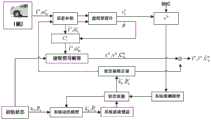
载体在正常运动情形下,沿横向(xb轴)和垂直方向(zb轴)的速度近似为零,联合步骤1中计算的载体前向方向(yb轴)运动速度,则可以获得载体在载体坐标系o-xbybzb下的三维速度观测量。如图3所示,利用扩展型卡尔曼滤波,估计出惯性系统的位置误差、速度误差、姿态误差以及加速度计和陀螺仪误差,进行提高导航精度。In the case of normal motion of the carrier, the speed along the lateral (xb axis) and vertical (zb axis) directions is approximately zero. Combined with the forward direction (yb axis) motion speed of the carrier calculated in step 1, the carrier can be obtained. 3D velocity observations in the carrier coordinate system oxb yb zb . As shown in Figure 3, the extended Kalman filter is used to estimate the position error, velocity error, attitude error, and accelerometer and gyroscope errors of the inertial system to improve the navigation accuracy.
首先建立系统状态方程;根据车载惯性导航系统特性,选取位置误差、速度误差、姿态误差、加速度计和陀螺仪误差组成15维状态量,如式(23)所示:Firstly, the system state equation is established; according to the characteristics of the vehicle inertial navigation system, the position error, velocity error, attitude error, accelerometer and gyroscope errors are selected to form a 15-dimensional state quantity, as shown in formula (23):
x==[δrn δvn εn γb db]T (23)x==[δrn δvn εn γb db ]T (23)
根据式(15)、(17)、(19)、(21)和(22),系统状态方程可由式(24)表示:According to equations (15), (17), (19), (21) and (22), the system state equation can be represented by equation (24):

其中,


其次建立系统观测方程;载体坐标系o-xbybzb下的速度矢量可以表示为:

其中,vb是vn的斜对称矩阵,表示载体坐标系下的速度;
根据式(23)和(25)可得系统观测量方程为:According to equations (23) and (25), the system observation equation can be obtained as:
z=Hx+v (26)z=Hx+v (26)
其中,z=δvb,
基于系统状态方程(24)和系统观测量方程(26),利用扩展型卡尔曼滤波计算得到位置误差、速度误差和姿态误差,来修正惯性导航系统中的位置、速度和姿态状态量,即可提高载体自主导航的精度。Based on the system state equation (24) and the system observation quantity equation (26), the position error, velocity error and attitude error are calculated by using the extended Kalman filter to correct the position, velocity and attitude state quantities in the inertial navigation system. Improve the accuracy of the carrier's autonomous navigation.
图3中,


Claims (1)
Translated fromChinese


Priority Applications (1)
| Application Number | Priority Date | Filing Date | Title |
|---|---|---|---|
| CN202010520820.9ACN111678514B (en) | 2020-06-09 | 2020-06-09 | Vehicle-mounted autonomous navigation method based on carrier motion condition constraint and single-axis rotation modulation |
Applications Claiming Priority (1)
| Application Number | Priority Date | Filing Date | Title |
|---|---|---|---|
| CN202010520820.9ACN111678514B (en) | 2020-06-09 | 2020-06-09 | Vehicle-mounted autonomous navigation method based on carrier motion condition constraint and single-axis rotation modulation |
Publications (2)
| Publication Number | Publication Date |
|---|---|
| CN111678514Atrue CN111678514A (en) | 2020-09-18 |
| CN111678514B CN111678514B (en) | 2023-03-28 |
Family
ID=72454450
Family Applications (1)
| Application Number | Title | Priority Date | Filing Date |
|---|---|---|---|
| CN202010520820.9AExpired - Fee RelatedCN111678514B (en) | 2020-06-09 | 2020-06-09 | Vehicle-mounted autonomous navigation method based on carrier motion condition constraint and single-axis rotation modulation |
Country Status (1)
| Country | Link |
|---|---|
| CN (1) | CN111678514B (en) |
Cited By (8)
| Publication number | Priority date | Publication date | Assignee | Title |
|---|---|---|---|---|
| CN113503882A (en)* | 2021-06-03 | 2021-10-15 | 北京自动化控制设备研究所 | Vehicle-mounted inertia/geomagnetic combined navigation method and device |
| CN114152269A (en)* | 2021-11-09 | 2022-03-08 | 南京邮电大学 | On-site calibration method for installation parameters of wheel installation inertia measurement unit |
| CN114234972A (en)* | 2022-03-01 | 2022-03-25 | 长沙金维信息技术有限公司 | Inertial navigation method for inertial navigation system |
| CN114777810A (en)* | 2022-04-13 | 2022-07-22 | 辽宁工程技术大学 | Strapdown inertial navigation system-level calibration method based on matrix decomposition |
| CN115079212A (en)* | 2021-03-16 | 2022-09-20 | 千寻位置网络有限公司 | IMU-based mobile window GNSS deception identification method and system |
| CN115112119A (en)* | 2022-08-11 | 2022-09-27 | 电子科技大学 | A vehicle navigation method based on LSTM neural network assistance |
| CN116481563A (en)* | 2023-02-27 | 2023-07-25 | 中国人民解放军国防科技大学 | Rate integration gyro measurement and control method and device based on virtual rotation of detection shaft |
| CN117053803A (en)* | 2023-10-10 | 2023-11-14 | 腾讯科技(深圳)有限公司 | Course information processing method, device, equipment and computer readable storage medium |
Citations (16)
| Publication number | Priority date | Publication date | Assignee | Title |
|---|---|---|---|---|
| US20030216865A1 (en)* | 2002-04-12 | 2003-11-20 | Ensco, Inc. | Inertial navigation system for mobile objects with constraints |
| US20110218753A1 (en)* | 2010-03-05 | 2011-09-08 | Seiko Epson Corporation | Posture information calculation device, posture information calculation system, posture information calculation method, and information storage medium |
| CN103712620A (en)* | 2013-11-27 | 2014-04-09 | 北京机械设备研究所 | Inertia autonomous navigation method by utilizing vehicle body non-integrity constraint |
| CN104567888A (en)* | 2014-12-25 | 2015-04-29 | 大连楼兰科技股份有限公司 | Attitude measurement method of inertial navigation vehicle based on online velocity correction |
| CN104977002A (en)* | 2015-06-12 | 2015-10-14 | 同济大学 | SINS/double OD-based inertial integrated navigation system and method |
| CN105737842A (en)* | 2016-03-23 | 2016-07-06 | 南京航空航天大学 | Vehicle-mounted autonomous navigation method based on rotary modulation and virtual odometer |
| CN106568449A (en)* | 2016-09-06 | 2017-04-19 | 北京理工大学 | GNSS/INS combination navigation method based on MEMS vehicle model assist and constraint |
| CN107289930A (en)* | 2016-04-01 | 2017-10-24 | 南京理工大学 | Pure inertia automobile navigation method based on MEMS Inertial Measurement Units |
| US20180112985A1 (en)* | 2016-10-26 | 2018-04-26 | The Charles Stark Draper Laboratory, Inc. | Vision-Inertial Navigation with Variable Contrast Tracking Residual |
| CN108845343A (en)* | 2018-07-03 | 2018-11-20 | 河北工业大学 | The vehicle positioning method that a kind of view-based access control model, GPS are merged with high-precision map |
| CN109631913A (en)* | 2019-01-30 | 2019-04-16 | 西安电子科技大学 | X-ray pulsar navigation localization method and system based on nonlinear prediction strong tracking Unscented kalman filtering |
| CN109945859A (en)* | 2019-04-01 | 2019-06-28 | 东南大学 | A Kinematically Constrained Strapdown Inertial Navigation Method with Adaptive H∞ Filtering |
| CN110285804A (en)* | 2019-06-26 | 2019-09-27 | 南京航空航天大学 | Vehicle Cooperative Navigation Method Based on Relative Motion Model Constraints |
| CN110780326A (en)* | 2019-09-26 | 2020-02-11 | 上海瀚所信息技术有限公司 | Vehicle-mounted integrated navigation system and positioning method |
| CN110887481A (en)* | 2019-12-11 | 2020-03-17 | 中国空气动力研究与发展中心低速空气动力研究所 | Carrier dynamic attitude estimation method based on MEMS inertial sensor |
| CN111076721A (en)* | 2020-01-19 | 2020-04-28 | 浙江融芯导航科技有限公司 | Fast-convergence inertial measurement unit installation attitude estimation method |
- 2020
- 2020-06-09CNCN202010520820.9Apatent/CN111678514B/ennot_activeExpired - Fee Related
Patent Citations (16)
| Publication number | Priority date | Publication date | Assignee | Title |
|---|---|---|---|---|
| US20030216865A1 (en)* | 2002-04-12 | 2003-11-20 | Ensco, Inc. | Inertial navigation system for mobile objects with constraints |
| US20110218753A1 (en)* | 2010-03-05 | 2011-09-08 | Seiko Epson Corporation | Posture information calculation device, posture information calculation system, posture information calculation method, and information storage medium |
| CN103712620A (en)* | 2013-11-27 | 2014-04-09 | 北京机械设备研究所 | Inertia autonomous navigation method by utilizing vehicle body non-integrity constraint |
| CN104567888A (en)* | 2014-12-25 | 2015-04-29 | 大连楼兰科技股份有限公司 | Attitude measurement method of inertial navigation vehicle based on online velocity correction |
| CN104977002A (en)* | 2015-06-12 | 2015-10-14 | 同济大学 | SINS/double OD-based inertial integrated navigation system and method |
| CN105737842A (en)* | 2016-03-23 | 2016-07-06 | 南京航空航天大学 | Vehicle-mounted autonomous navigation method based on rotary modulation and virtual odometer |
| CN107289930A (en)* | 2016-04-01 | 2017-10-24 | 南京理工大学 | Pure inertia automobile navigation method based on MEMS Inertial Measurement Units |
| CN106568449A (en)* | 2016-09-06 | 2017-04-19 | 北京理工大学 | GNSS/INS combination navigation method based on MEMS vehicle model assist and constraint |
| US20180112985A1 (en)* | 2016-10-26 | 2018-04-26 | The Charles Stark Draper Laboratory, Inc. | Vision-Inertial Navigation with Variable Contrast Tracking Residual |
| CN108845343A (en)* | 2018-07-03 | 2018-11-20 | 河北工业大学 | The vehicle positioning method that a kind of view-based access control model, GPS are merged with high-precision map |
| CN109631913A (en)* | 2019-01-30 | 2019-04-16 | 西安电子科技大学 | X-ray pulsar navigation localization method and system based on nonlinear prediction strong tracking Unscented kalman filtering |
| CN109945859A (en)* | 2019-04-01 | 2019-06-28 | 东南大学 | A Kinematically Constrained Strapdown Inertial Navigation Method with Adaptive H∞ Filtering |
| CN110285804A (en)* | 2019-06-26 | 2019-09-27 | 南京航空航天大学 | Vehicle Cooperative Navigation Method Based on Relative Motion Model Constraints |
| CN110780326A (en)* | 2019-09-26 | 2020-02-11 | 上海瀚所信息技术有限公司 | Vehicle-mounted integrated navigation system and positioning method |
| CN110887481A (en)* | 2019-12-11 | 2020-03-17 | 中国空气动力研究与发展中心低速空气动力研究所 | Carrier dynamic attitude estimation method based on MEMS inertial sensor |
| CN111076721A (en)* | 2020-01-19 | 2020-04-28 | 浙江融芯导航科技有限公司 | Fast-convergence inertial measurement unit installation attitude estimation method |
Non-Patent Citations (3)
| Title |
|---|
| ALEKSANDR BRANDT 等: "Constrained Navigation Algorithms for Strapdown Inertial Navigation Systems with Reduced Set of Sensors", 《PROCEEDINGS OF THE AMERICAN CONTROL CONFERENCE》* |
| SHI PENG 等: "The Algorithm of MIMU/Odometer Integrated Navigation System Aided by Nonholonomic Constraints", 《2013 INTERNATIONAL CONFERENCE ON MECHATRONIC SCIENCES, ELECTRIC ENGINEERING AND COMPUTER (MEC)》* |
| 翁浚 等: "重力扰动对高精度激光陀螺惯导系统ZUPT的影响分析与补偿", 《系统工程与电子技术》* |
Cited By (14)
| Publication number | Priority date | Publication date | Assignee | Title |
|---|---|---|---|---|
| CN115079212A (en)* | 2021-03-16 | 2022-09-20 | 千寻位置网络有限公司 | IMU-based mobile window GNSS deception identification method and system |
| CN113503882A (en)* | 2021-06-03 | 2021-10-15 | 北京自动化控制设备研究所 | Vehicle-mounted inertia/geomagnetic combined navigation method and device |
| CN113503882B (en)* | 2021-06-03 | 2023-09-12 | 北京自动化控制设备研究所 | A vehicle-mounted inertial/geomagnetic integrated navigation method and device |
| CN114152269B (en)* | 2021-11-09 | 2024-03-22 | 南京邮电大学 | On-site calibration method for installation parameters of wheel installation inertia measurement unit |
| CN114152269A (en)* | 2021-11-09 | 2022-03-08 | 南京邮电大学 | On-site calibration method for installation parameters of wheel installation inertia measurement unit |
| CN114234972A (en)* | 2022-03-01 | 2022-03-25 | 长沙金维信息技术有限公司 | Inertial navigation method for inertial navigation system |
| CN114234972B (en)* | 2022-03-01 | 2022-05-24 | 长沙金维信息技术有限公司 | Inertial navigation method for inertial navigation system |
| CN114777810A (en)* | 2022-04-13 | 2022-07-22 | 辽宁工程技术大学 | Strapdown inertial navigation system-level calibration method based on matrix decomposition |
| CN114777810B (en)* | 2022-04-13 | 2025-04-11 | 辽宁工程技术大学 | A Strapdown Inertial Navigation System-Level Calibration Method Based on Matrix Decomposition |
| CN115112119A (en)* | 2022-08-11 | 2022-09-27 | 电子科技大学 | A vehicle navigation method based on LSTM neural network assistance |
| CN115112119B (en)* | 2022-08-11 | 2025-04-29 | 电子科技大学 | A vehicle navigation method based on LSTM neural network assistance |
| CN116481563A (en)* | 2023-02-27 | 2023-07-25 | 中国人民解放军国防科技大学 | Rate integration gyro measurement and control method and device based on virtual rotation of detection shaft |
| CN117053803B (en)* | 2023-10-10 | 2024-01-26 | 腾讯科技(深圳)有限公司 | Course information processing method, device, equipment and computer readable storage medium |
| CN117053803A (en)* | 2023-10-10 | 2023-11-14 | 腾讯科技(深圳)有限公司 | Course information processing method, device, equipment and computer readable storage medium |
Also Published As
| Publication number | Publication date |
|---|---|
| CN111678514B (en) | 2023-03-28 |
Similar Documents
| Publication | Publication Date | Title |
|---|---|---|
| CN111678514B (en) | Vehicle-mounted autonomous navigation method based on carrier motion condition constraint and single-axis rotation modulation | |
| Wang et al. | Consistent ST-EKF for long distance land vehicle navigation based on SINS/OD integration | |
| CN104061899B (en) | A method for estimating vehicle roll angle and pitch angle based on Kalman filter | |
| CN103557876B (en) | A kind of inertial navigation Initial Alignment Method for antenna tracking stable platform | |
| Niu et al. | Wheel-INS: A wheel-mounted MEMS IMU-based dead reckoning system | |
| US20100019963A1 (en) | Vehicular navigation and positioning system | |
| CN109000640B (en) | Vehicle GNSS/INS integrated navigation method based on discrete grey neural network model | |
| CN101963513B (en) | Alignment method for eliminating lever arm effect error of strapdown inertial navigation system (SINS) of underwater carrier | |
| CN111156994A (en) | INS/DR & GNSS loose integrated navigation method based on MEMS inertial component | |
| CN110285804B (en) | Vehicle collaborative navigation method based on relative motion model constraint | |
| WO2020114301A1 (en) | Magnetic-side roll angular velocity information-based rotary shell flight posture high-precision estimation method | |
| CN107144284A (en) | Inertial navigation combination navigation method is aided in based on the vehicle dynamic model that CKF is filtered | |
| JP5602070B2 (en) | POSITIONING DEVICE, POSITIONING METHOD OF POSITIONING DEVICE, AND POSITIONING PROGRAM | |
| CN105074382B (en) | dump truck | |
| CN103743414A (en) | Initial alignment method of speedometer-assisted strapdown inertial navigation system during running | |
| Wu et al. | A comparison of three measurement models for the wheel-mounted MEMS IMU-based dead reckoning system | |
| CN104697526A (en) | Strapdown inertial navitation system and control method for agricultural machines | |
| Wang et al. | Accuracy and robustness of ODO/NHC measurement models for wheeled robot positioning | |
| CN106568449A (en) | GNSS/INS combination navigation method based on MEMS vehicle model assist and constraint | |
| CN106885587A (en) | The lower outer lever arm effect errors compensation method of inertia/GPS integrated navigations of rotor disturbance | |
| Park et al. | MEMS 3D DR/GPS integrated system for land vehicle application robust to GPS outages | |
| CN101900573A (en) | A Method for Realizing Motion Alignment of Land-Used Inertial Navigation System | |
| US10048074B1 (en) | Polar region operating attitude and heading reference system | |
| CN105737842A (en) | Vehicle-mounted autonomous navigation method based on rotary modulation and virtual odometer | |
| Wang et al. | Performance analysis of GNSS/MIMU tight fusion positioning model with complex scene feature constraints |
Legal Events
| Date | Code | Title | Description |
|---|---|---|---|
| PB01 | Publication | ||
| PB01 | Publication | ||
| SE01 | Entry into force of request for substantive examination | ||
| SE01 | Entry into force of request for substantive examination | ||
| GR01 | Patent grant | ||
| GR01 | Patent grant | ||
| CF01 | Termination of patent right due to non-payment of annual fee | ||
| CF01 | Termination of patent right due to non-payment of annual fee | Granted publication date:20230328 |