CN111671520A - A sheath drive device adapted to a catheter manipulator - Google Patents
A sheath drive device adapted to a catheter manipulatorDownload PDFInfo
- Publication number
- CN111671520A CN111671520ACN202010534692.3ACN202010534692ACN111671520ACN 111671520 ACN111671520 ACN 111671520ACN 202010534692 ACN202010534692 ACN 202010534692ACN 111671520 ACN111671520 ACN 111671520A
- Authority
- CN
- China
- Prior art keywords
- sheath
- sheath tube
- tube
- rod
- catheter
- Prior art date
- Legal status (The legal status is an assumption and is not a legal conclusion. Google has not performed a legal analysis and makes no representation as to the accuracy of the status listed.)
- Granted
Links
Images


Classifications
- A—HUMAN NECESSITIES
- A61—MEDICAL OR VETERINARY SCIENCE; HYGIENE
- A61B—DIAGNOSIS; SURGERY; IDENTIFICATION
- A61B34/00—Computer-aided surgery; Manipulators or robots specially adapted for use in surgery
- A61B34/30—Surgical robots
- A—HUMAN NECESSITIES
- A61—MEDICAL OR VETERINARY SCIENCE; HYGIENE
- A61B—DIAGNOSIS; SURGERY; IDENTIFICATION
- A61B18/00—Surgical instruments, devices or methods for transferring non-mechanical forms of energy to or from the body
- A61B18/04—Surgical instruments, devices or methods for transferring non-mechanical forms of energy to or from the body by heating
- A61B18/12—Surgical instruments, devices or methods for transferring non-mechanical forms of energy to or from the body by heating by passing a current through the tissue to be heated, e.g. high-frequency current
- A—HUMAN NECESSITIES
- A61—MEDICAL OR VETERINARY SCIENCE; HYGIENE
- A61B—DIAGNOSIS; SURGERY; IDENTIFICATION
- A61B34/00—Computer-aided surgery; Manipulators or robots specially adapted for use in surgery
- A61B34/70—Manipulators specially adapted for use in surgery
- A—HUMAN NECESSITIES
- A61—MEDICAL OR VETERINARY SCIENCE; HYGIENE
- A61B—DIAGNOSIS; SURGERY; IDENTIFICATION
- A61B18/00—Surgical instruments, devices or methods for transferring non-mechanical forms of energy to or from the body
- A61B2018/00571—Surgical instruments, devices or methods for transferring non-mechanical forms of energy to or from the body for achieving a particular surgical effect
- A61B2018/00577—Ablation
- A—HUMAN NECESSITIES
- A61—MEDICAL OR VETERINARY SCIENCE; HYGIENE
- A61B—DIAGNOSIS; SURGERY; IDENTIFICATION
- A61B34/00—Computer-aided surgery; Manipulators or robots specially adapted for use in surgery
- A61B34/30—Surgical robots
- A61B2034/301—Surgical robots for introducing or steering flexible instruments inserted into the body, e.g. catheters or endoscopes
- A—HUMAN NECESSITIES
- A61—MEDICAL OR VETERINARY SCIENCE; HYGIENE
- A61B—DIAGNOSIS; SURGERY; IDENTIFICATION
- A61B34/00—Computer-aided surgery; Manipulators or robots specially adapted for use in surgery
- A61B34/30—Surgical robots
- A61B2034/305—Details of wrist mechanisms at distal ends of robotic arms
Landscapes
- Health & Medical Sciences (AREA)
- Surgery (AREA)
- Engineering & Computer Science (AREA)
- Life Sciences & Earth Sciences (AREA)
- Biomedical Technology (AREA)
- Public Health (AREA)
- Nuclear Medicine, Radiotherapy & Molecular Imaging (AREA)
- Veterinary Medicine (AREA)
- General Health & Medical Sciences (AREA)
- Heart & Thoracic Surgery (AREA)
- Medical Informatics (AREA)
- Molecular Biology (AREA)
- Animal Behavior & Ethology (AREA)
- Robotics (AREA)
- Physics & Mathematics (AREA)
- Otolaryngology (AREA)
- Plasma & Fusion (AREA)
- Infusion, Injection, And Reservoir Apparatuses (AREA)
- Media Introduction/Drainage Providing Device (AREA)
Abstract
Description
Translated fromChinese技术领域technical field
本发明涉及医疗器械技术领域,特别是涉及一种适配导管机械臂的鞘管驱动装置。The invention relates to the technical field of medical devices, in particular to a sheath tube driving device adapted to a catheter manipulator.
背景技术Background technique
在射频消融手术中,当操作导管精确定位目标靶点遇到困难时,经常需要同时或分别操作导管和鞘管,通过鞘管的旋转或进退辅助导管到达定位比较困难的目标靶点。目前,这种导管和鞘管的联动操作,只能通过术者手动操控才能实现,必要时还需要手术助手协助完成。也就是说,现有的导管机械臂需要手动操作鞘管进行辅助定位目标靶点,而由于手动操作存在很大人为的因素,所以会直接影响定位目标靶点的精度。In radiofrequency ablation, when it is difficult to precisely locate the target by operating the catheter, it is often necessary to operate the catheter and sheath at the same time or separately, and assist the catheter to reach the difficult-to-locate target by rotating or advancing and retracting the sheath. At present, the linkage operation between the catheter and the sheath can only be achieved by manual manipulation by the operator, and when necessary, the assistance of a surgical assistant is required. That is to say, the existing catheter manipulator needs to manually operate the sheath to assist in locating the target point, and since there are a lot of human factors in the manual operation, it will directly affect the accuracy of locating the target point.
发明内容SUMMARY OF THE INVENTION
本发明提供了一种适配导管机械臂的鞘管驱动装置,以解决现有技术中人工手动操控鞘管辅助定位目标靶点时定位成功率低的问题。The invention provides a sheath tube driving device adapted to a catheter manipulator, so as to solve the problem of low positioning success rate when manually manually manipulating the sheath tube to assist in positioning the target point in the prior art.
本发明提供了一种适配导管机械臂的鞘管驱动装置,包括:鞘管旋转轴、伸缩器和鞘管连接器;所述鞘管旋转轴,与导管机械臂连接,套在所述导管机械臂的导管旋转轴外;所述伸缩器的一端与所述鞘管旋转轴连接,另一端与所述鞘管连接器连接,导管在所述伸缩器内穿过,所述鞘管连接器上固定有鞘管;通过所述鞘管旋转轴和所述伸缩器推动所述鞘管进行往返运动。The invention provides a sheath tube driving device adapted to a catheter manipulator, comprising: a sheath tube rotation shaft, a retractor and a sheath tube connector; the sheath tube rotation shaft is connected with the catheter manipulator and is sleeved on the catheter Outside the catheter rotation axis of the robotic arm; one end of the retractor is connected to the sheath rotation axis, and the other end is connected to the sheath connector, the catheter passes through the retractor, and the sheath connector A sheath tube is fixed on it; the sheath tube is pushed back and forth through the sheath tube rotating shaft and the retractor.
可选地,所述鞘管驱动装置还包括:第一驱动器;Optionally, the sheath driving device further comprises: a first driver;
所述第一驱动器根据接收到的第一触发信号驱动所述鞘管旋转轴沿所述导管旋转轴的中心线方向进行往返移动,以推动所述鞘管进行往返运动。The first driver drives the sheath rotating shaft to reciprocate along the direction of the center line of the catheter rotating shaft according to the received first trigger signal, so as to push the sheath to move back and forth.
可选地,所述鞘管驱动装置还包括:传动机构;通过所述传动机构将所述第一驱动器的动力传动到所述鞘管旋转轴。Optionally, the sheath tube driving device further comprises: a transmission mechanism; the power of the first driver is transmitted to the sheath tube rotation shaft through the transmission mechanism.
可选地,所述传动机构是直齿轮,所述直齿轮设置在所述导管旋转轴外。Optionally, the transmission mechanism is a spur gear, and the spur gear is arranged outside the rotating shaft of the catheter.
可选地,所述鞘管驱动装置还包括:第二驱动器;Optionally, the sheath tube driving device further comprises: a second driver;
所述第二驱动器根据接收到的第二触发信号驱动所述伸缩器沿所述导管旋转轴的中心线方向进行往返移动,以推动所述鞘管进行往返运动。The second driver drives the retractor to reciprocate along the direction of the center line of the catheter rotation axis according to the received second trigger signal, so as to push the sheath to reciprocate.
可选地,所述伸缩器为多节套接在一起的可伸缩的空心连接杆。Optionally, the retractor is a telescopic hollow connecting rod that is sleeved together with multiple sections.
可选地,所述伸缩器为两节套接在一起的可伸缩的空心连接杆,分别是母杆和子杆;Optionally, the retractor is a telescopic hollow connecting rod sleeved together by two sections, which are a main rod and a sub rod respectively;
所述母杆的第一端与所述鞘管旋转轴连接,所述母杆内为中空结构,所述子杆的第一端通过所述母杆的第二端套入所述中空结构内,所述子杆的第二端与所述鞘管连接器连接;The first end of the mother rod is connected with the sheath tube rotating shaft, the inside of the mother rod is a hollow structure, and the first end of the sub-rod is sleeved into the hollow structure through the second end of the mother rod , the second end of the sub-rod is connected with the sheath connector;
通过所述子杆在所述母杆内的伸缩,以推动与所述鞘管的运动。The movement with the sheath tube is promoted through the extension and retraction of the sub-rod in the main rod.
可选地,所述伸缩器为对称设置的两根连接杆。Optionally, the retractor is two connecting rods arranged symmetrically.
可选地,所述鞘管驱动装置还包括:输液管撑杆;所述输液管撑杆,一端固定在所述鞘管连接器上,另一端固定在所述导管机械臂上,所述输液管撑杆与输液管绑定在一起,以对所述输液管进行支撑。Optionally, the sheath tube driving device further comprises: an infusion tube support rod; one end of the infusion tube support rod is fixed on the sheath tube connector, and the other end is fixed on the catheter mechanical arm, and the infusion tube support rod is The tube support rod is bound with the infusion tube to support the infusion tube.
可选地,所述输液管撑杆为柔性钢丝。Optionally, the infusion tube strut is a flexible steel wire.
可选地,所述鞘管连接器为卡扣件,通过所述卡扣件卡扣在所述鞘管的末端。Optionally, the sheath tube connector is a clip, which is clipped on the end of the sheath tube by the clip.
本发明有益效果如下:The beneficial effects of the present invention are as follows:
本发明设置了鞘管驱动装置,通过鞘管驱动装置的鞘管旋转轴和伸缩器来共同推动鞘管进行往返移动,实现鞘管的自动且按需移动,从而有效解决现有技术中手动操控鞘管辅助定位目标靶点定位成功率低的问题。The invention is provided with a sheath tube driving device, and the sheath tube is jointly pushed to move back and forth by the sheath tube rotating shaft and the retractor of the sheath tube driving device, so as to realize the automatic and on-demand movement of the sheath tube, thereby effectively solving the problem of manual control in the prior art. The problem of low success rate of sheath-assisted positioning of the target target.
附图说明Description of drawings
图1是本发明实施例提供的一种适配导管机械臂的鞘管驱动装置的结构示意图;1 is a schematic structural diagram of a sheath drive device adapted to a catheter manipulator provided by an embodiment of the present invention;
图2是本发明实施例提供的另一种适配导管机械臂的鞘管驱动装置结构示意图;2 is a schematic structural diagram of another sheath drive device adapted to a catheter manipulator provided by an embodiment of the present invention;
图3是本发明实施例提供的再一种适配导管机械臂的鞘管驱动装置结构示意图;3 is a schematic structural diagram of yet another sheath drive device adapted to a catheter manipulator provided by an embodiment of the present invention;
图4是本发明实施例提供的鞘管尾部的结构示意图。FIG. 4 is a schematic structural diagram of a sheath tube tail provided by an embodiment of the present invention.
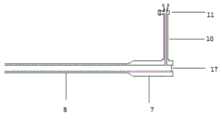
附图标记说明:1导管,2导管机械臂,3导管旋转轴,4鞘管旋转轴、5伸缩器,5-1母杆,5-2子杆,6鞘管连接器,7、鞘管尾部,8鞘管,9输液管,10、测管,11测管三通,12输液管撑杆,13绑定件,14按钮、15第一驱动器,16传动机构,17入口密封薄膜。Description of reference numerals: 1 catheter, 2 catheter manipulator, 3 catheter rotation axis, 4 sheath tube rotation axis, 5 retractor, 5-1 female rod, 5-2 sub-rod, 6 sheath tube connector, 7, sheath tube Tail, 8 sheath tube, 9 infusion tube, 10, measuring tube, 11 measuring tube tee, 12 infusion tube strut, 13 binding piece, 14 button, 15 first driver, 16 transmission mechanism, 17 inlet sealing film.
具体实施方式Detailed ways
本发明实施例通过鞘管驱动装置的鞘管旋转轴和伸缩器来共同推动鞘管进行往返移动,实现鞘管的自动且按需移动,从而有效解决现有技术中手动操控鞘管辅助定位目标靶点定位成功率低的问题。以下结合附图以及实施例,对本发明进行进一步详细说明。应当理解,此处所描述的具体实施例仅仅用以解释本发明,并不限定本发明。In the embodiment of the present invention, the sheath tube is jointly driven by the sheath tube rotating shaft and the retractor of the sheath tube drive device to move back and forth, so as to realize the automatic and on-demand movement of the sheath tube, thereby effectively solving the problem of manually controlling the sheath tube to assist the positioning target in the prior art. The problem of low target positioning success rate. The present invention will be further described in detail below with reference to the accompanying drawings and embodiments. It should be understood that the specific embodiments described herein are only used to illustrate the present invention, but not to limit the present invention.
本发明实施例提供了一种适配导管机械臂的鞘管驱动装置,参见图1,该装置包括:鞘管旋转轴、伸缩器5和鞘管连接器6;An embodiment of the present invention provides a sheath drive device adapted to a catheter manipulator. Referring to FIG. 1 , the device includes: a sheath rotation shaft, a
所述鞘管鞘管旋转轴4,与导管机械臂2连接,套在所述导管机械臂2的导管旋转轴3外;The sheath tube sheath
所述伸缩器5的一端与所述鞘管鞘管旋转轴4连接,另一端与所述鞘管连接器6连接,导管1在所述伸缩器5内穿过;One end of the
所述鞘管连接器6,用于与所述鞘管8连接;The
具体地,本发明实施例所述鞘管连接器6为卡扣件,所述卡扣件将所述鞘管7尾部与鞘管驱动装置卡扣在一起,并且该卡扣件上还设有按钮14,通过该按钮14可以方便的拆卸和安装所述鞘管连接器6。Specifically, the
通过所述鞘管旋转轴4和所述伸缩器5推动所述鞘管8进行往返运动。The
也就是说,本发明实施例是通过鞘管旋转轴4和伸缩器5来推动鞘管8进行往返移动,实现鞘管8的自动且按需移动,并最终提高了鞘管8辅助定位目标靶点的定位成功率。That is to say, in the embodiment of the present invention, the
如图2和图3所示,具体实施时,本发明实施例所述鞘管驱动装置还包括:第一驱动器,本发明实施例通过该第一驱动器根据第一触发信号驱动所述鞘管旋转轴4沿所述导管旋转轴3的中心线方向进行往返移动,以推动所述鞘管8进行往返运动。As shown in FIGS. 2 and 3 , during specific implementation, the sheath driving device according to the embodiment of the present invention further includes: a first driver, through which the sheath is driven to rotate according to a first trigger signal in the embodiment of the present invention. The
即,本发明实施例通过第一驱动器来驱动鞘管旋转轴4沿着导管旋转轴3进行往复移动,并通过鞘管旋转轴4最终带动鞘管8的移动。That is, in the embodiment of the present invention, the first driver is used to drive the sheath
具体实施时,本发明实施例是通过传动机构来将所述驱动器的动力传动到所述鞘管旋转轴4。During specific implementation, in the embodiment of the present invention, the power of the driver is transmitted to the sheath
例如,在具体实施时,本领域技术人员可以通过在所述导管旋转轴3外设置一个直齿轮,通过该直齿轮将第一驱动器的动力传递到鞘管旋转轴4,使得旋转4轴沿着导管旋转轴3的中心线方向进行往返移动,并最终实现推动鞘管8的往返运动。For example, in the specific implementation, those skilled in the art can set a spur gear outside the
具体实施时,本发明实施例中,所述鞘管驱动装置还包括:第二驱动器;During specific implementation, in the embodiment of the present invention, the sheath tube driving device further includes: a second driver;
所述第二驱动器根据第二触发信号驱动所述伸缩器5沿所述鞘管旋转轴4的中心线方向进行往返移动,以推动所述鞘管8进行往返运动。The second driver drives the
具体来说,本发明实施例是通过一个驱动器来推动伸缩器5进行伸缩,从而推动鞘管8进行往返运动。Specifically, in the embodiment of the present invention, a driver is used to push the
总体来说,本发明实施例是通过伸缩器5的伸缩实现对鞘管驱动的粗调,即,通过第二驱动器驱动伸缩器5沿鞘管旋转轴4的中心线方向进行相对大尺寸的移动,再通过控制鞘管旋转轴4沿鞘管旋转轴4的中心线方向进行相对小尺寸的移动,从而实现对鞘管8驱动的精调,通过上述的粗调和精调最终实现鞘管8的自动且按需移动,从而提高了鞘管8辅助定位目标靶点的定位成功率。Generally speaking, in the embodiment of the present invention, the coarse adjustment of the sheath tube drive is realized by the expansion and contraction of the
需要说明的是,本发明实施例中第一驱动器和第二驱动器可以是各种驱动电机,只要能实现驱动鞘管旋转轴4和伸缩器5的运动即可,本发明对此不作具体限定。另外,本发明实施例中的传动机构可以是各种能够将驱动器的动力进行传动的器件,例如,可以将传动机构设置为直齿轮和螺旋连接等等,只要能够通过驱动器控制被推动件进行往返运动即可。It should be noted that, in the embodiment of the present invention, the first driver and the second driver may be various driving motors, as long as the movement of the
在具体实施时,本领域技术人员可以根据实际情况来设置各个驱动器和传动机构的位置,如,将本发明实施例中的第一驱动器和直齿轮均设置在鞘管旋转轴4内,通过主机或者专用控制器以有线或者无线手段实现向第一驱动器发送触发信号,等等,相应的,本领域技术人员也可以根据上述方法来设置第二驱动器以及与其对应的传动机构,例如,将第二驱动器以及与其对应的传动机构均设置在鞘管旋转轴4或者机械臂上,通过主机或者专用控制器以有线或者无线手段实现向第二驱动器发送触发信号,具体本发明实施例对此不作详细赘述。During the specific implementation, those skilled in the art can set the positions of each driver and transmission mechanism according to the actual situation. Or the dedicated controller can send the trigger signal to the first driver by wired or wireless means, etc. Correspondingly, those skilled in the art can also set the second driver and its corresponding transmission mechanism according to the above method. The driver and its corresponding transmission mechanism are all arranged on the
进一步地,本发明实施例中,所述伸缩器5为多节套接在一起的可伸缩的空心的连接杆杆,且所述连接杆按照连接杆的直径从大到小或者从小到大的顺序依次套接在一起。Further, in the embodiment of the present invention, the
也就是说,本发明实施例中的伸缩器5由多个不同直径的级联在一起的连接杆,即,将直径小的连接杆套接在直径大的连接杆内,通过控制连接杆的伸缩,从而实现对鞘管8驱动的粗调。That is to say, the
具体实施时,为了保持控制的稳定性,本发明实施例的伸缩器5设置了两根连接杆,如图1和2所示,该两根连接杆对称设置,以更好进行精确定位。During specific implementation, in order to maintain control stability, the
如图2所示,具体实施时,本发明实施例可以将所述连接杆为两节,分别是母杆5-1和子杆5-2;As shown in FIG. 2 , in the specific implementation, the embodiment of the present invention may divide the connecting rod into two sections, which are the main rod 5-1 and the sub rod 5-2 respectively;
所述母杆5-1的第一端与所述鞘管旋转轴4连接,所述母杆5-1内为中空结构,所述子杆5-2的第一端通过所述母杆5-1的第二端套入所述中空结构内,所述子杆5-2的第二端与所述鞘管连接器6连接;通过所述子杆5-2在所述母杆5-1内的伸缩,以推动与所述鞘管8的运动。The first end of the main rod 5-1 is connected to the sheath
具体来说,本发明实施例是通过第二驱动器来控制连接杆的伸缩,从而实现对鞘管8驱动的粗调。Specifically, in the embodiment of the present invention, the extension and retraction of the connecting rod is controlled by the second driver, so as to realize the rough adjustment of the driving of the
需要说明的是,为了增强连接杆的稳定性,本发明实施例对称设置了两套连接杆,导管1沿着两套连接杆中间通过,该两套连接杆通过第二驱动器的控制实现同步伸缩运动。It should be noted that, in order to enhance the stability of the connecting rods, two sets of connecting rods are symmetrically arranged in the embodiment of the present invention, the
当然,在具体实施时,本领域技术人员也可以设置一个级联的套筒,即,将多个不同直径的套筒级联在一起的,导管1沿着在套筒内部通过,通过驱动器控制套筒的伸缩,也可以实现对鞘管8驱动的粗调。Of course, in the specific implementation, those skilled in the art can also set a cascaded sleeve, that is, a plurality of sleeves with different diameters are cascaded together, the
在具体实施时,本发明实施例中,所述鞘管驱动装置还包括:输液管撑杆;During specific implementation, in the embodiment of the present invention, the sheath tube driving device further comprises: an infusion tube support rod;
所述输液管撑杆,一端固定在所述鞘管连接器6上,另一端固定在所述导管机械臂2上,所述输液管撑杆与输液管9通过绑定件绑定在一起,以对所述输液管9进行支撑。One end of the infusion tube support rod is fixed on the
具体实施时,本发明实施例输液管撑杆为柔性钢丝,即通过连接件将该柔性钢丝的两端分别固定到鞘管连接器6和导管机械臂2上,并将输液管9与柔性钢丝通过绑定件绑定在一起,从而通过柔性钢丝对输液管9进行支撑,并通过柔性钢丝来控制输液管9的运动,以避免输液管9缠绕在鞘管驱动装置上。In specific implementation, the infusion tube support rod in the embodiment of the present invention is a flexible steel wire, that is, the two ends of the flexible steel wire are respectively fixed to the
如图4所示,本发明实施例的鞘管8包括:鞘管尾部7、鞘管8、测管10、测管三通11以及入口密封薄膜17,由于本领域技术人员可以获取到鞘管的今天结构,因此,本发明实施例对此不作详细说明。As shown in FIG. 4 , the
综上,本发明实施例的鞘管驱动装置,可通过旋转轴和伸缩器来共同推动鞘管进行往返移动,实现鞘管的自动且按需移动,从而提高了定位目标靶点的成功率。To sum up, the sheath tube driving device of the embodiment of the present invention can jointly push the sheath tube to move back and forth through the rotating shaft and the retractor, so as to realize the automatic and on-demand movement of the sheath tube, thereby improving the success rate of locating the target point.
尽管为示例目的,已经公开了本发明的优选实施例,本领域的技术人员将意识到各种改进、增加和取代也是可能的,因此,本发明的范围应当不限于上述实施例。Although the preferred embodiments of the present invention have been disclosed for illustrative purposes, those skilled in the art will appreciate that various modifications, additions and substitutions are possible, and therefore, the scope of the present invention should not be limited to the above-described embodiments.
Claims (10)
Translated fromChinesePriority Applications (1)
| Application Number | Priority Date | Filing Date | Title |
|---|---|---|---|
| CN202010534692.3ACN111671520B (en) | 2020-06-12 | 2020-06-12 | Sheath driving device of adaptive catheter mechanical arm |
Applications Claiming Priority (1)
| Application Number | Priority Date | Filing Date | Title |
|---|---|---|---|
| CN202010534692.3ACN111671520B (en) | 2020-06-12 | 2020-06-12 | Sheath driving device of adaptive catheter mechanical arm |
Publications (2)
| Publication Number | Publication Date |
|---|---|
| CN111671520Atrue CN111671520A (en) | 2020-09-18 |
| CN111671520B CN111671520B (en) | 2025-07-22 |
Family
ID=72454799
Family Applications (1)
| Application Number | Title | Priority Date | Filing Date |
|---|---|---|---|
| CN202010534692.3AActiveCN111671520B (en) | 2020-06-12 | 2020-06-12 | Sheath driving device of adaptive catheter mechanical arm |
Country Status (1)
| Country | Link |
|---|---|
| CN (1) | CN111671520B (en) |
Cited By (2)
| Publication number | Priority date | Publication date | Assignee | Title |
|---|---|---|---|---|
| CN113331936A (en)* | 2021-05-20 | 2021-09-03 | 扬州大学附属医院 | Holding device of long sheath for radiofrequency ablation |
| CN115582859A (en)* | 2022-11-15 | 2023-01-10 | 上海中认尚科新能源技术有限公司 | Novel multi-structure columnar telescopic mechanism with high shock resistance and high precision |
Citations (17)
| Publication number | Priority date | Publication date | Assignee | Title |
|---|---|---|---|---|
| US20020177789A1 (en)* | 2001-05-06 | 2002-11-28 | Ferry Steven J. | System and methods for advancing a catheter |
| US20050203382A1 (en)* | 2004-02-23 | 2005-09-15 | Assaf Govari | Robotically guided catheter |
| WO2006091597A1 (en)* | 2005-02-22 | 2006-08-31 | Cardiofocus, Inc. | Deflectable sheath catheters |
| EP1846076A2 (en)* | 2005-02-08 | 2007-10-24 | Boston Scientific Scimed, Inc. | Device for canulation and occlusion of uterine arteries |
| CN201899524U (en)* | 2010-12-22 | 2011-07-20 | 乐普(北京)医疗器械股份有限公司 | Conveying device |
| US20130035749A1 (en)* | 2011-08-02 | 2013-02-07 | Cook Medical Technologies Llc | Delivery device having a variable diameter introducer sheath |
| CN104013465A (en)* | 2014-05-28 | 2014-09-03 | 雷东 | Medical bipolar ablation device with angle adjusting function |
| CN104800954A (en)* | 2015-05-20 | 2015-07-29 | 湖南埃普特医疗器械有限公司 | Valve-adjustable catheter sheath |
| US20160193449A1 (en)* | 2015-01-02 | 2016-07-07 | Jaime Eduardo Sarabia | Steerable introducer sheath assembly |
| CN107693089A (en)* | 2016-08-09 | 2018-02-16 | 上海交通大学医学院附属新华医院 | Three-dimensional atrial septal puncture system |
| CN207804717U (en)* | 2017-04-25 | 2018-09-04 | 重庆医科大学附属永川医院 | Reinforced transfusion scalp acupuncture |
| CN208852216U (en)* | 2018-06-27 | 2019-05-14 | 杭州唯强医疗科技有限公司 | Introducer sheaths and dilation components |
| WO2020043204A1 (en)* | 2018-08-31 | 2020-03-05 | 上海微创心通医疗科技有限公司 | Delivery device |
| CN110898317A (en)* | 2019-12-10 | 2020-03-24 | 复旦大学附属妇产科医院 | Uterine neck sheath tube for oviduct interventional embolization |
| CN210408508U (en)* | 2019-04-11 | 2020-04-28 | 杭州唯强医疗科技有限公司 | Adjustable bending device for sheath tube |
| CN210541957U (en)* | 2019-06-18 | 2020-05-19 | 上海善迪医疗科技有限公司 | Different-shaft driving type blood vessel stent conveying system |
| CN212630893U (en)* | 2020-06-12 | 2021-03-02 | 绍兴梅奥心磁医疗科技有限公司 | Sheath pipe driving device adaptive to catheter mechanical arm |
- 2020
- 2020-06-12CNCN202010534692.3Apatent/CN111671520B/enactiveActive
Patent Citations (17)
| Publication number | Priority date | Publication date | Assignee | Title |
|---|---|---|---|---|
| US20020177789A1 (en)* | 2001-05-06 | 2002-11-28 | Ferry Steven J. | System and methods for advancing a catheter |
| US20050203382A1 (en)* | 2004-02-23 | 2005-09-15 | Assaf Govari | Robotically guided catheter |
| EP1846076A2 (en)* | 2005-02-08 | 2007-10-24 | Boston Scientific Scimed, Inc. | Device for canulation and occlusion of uterine arteries |
| WO2006091597A1 (en)* | 2005-02-22 | 2006-08-31 | Cardiofocus, Inc. | Deflectable sheath catheters |
| CN201899524U (en)* | 2010-12-22 | 2011-07-20 | 乐普(北京)医疗器械股份有限公司 | Conveying device |
| US20130035749A1 (en)* | 2011-08-02 | 2013-02-07 | Cook Medical Technologies Llc | Delivery device having a variable diameter introducer sheath |
| CN104013465A (en)* | 2014-05-28 | 2014-09-03 | 雷东 | Medical bipolar ablation device with angle adjusting function |
| US20160193449A1 (en)* | 2015-01-02 | 2016-07-07 | Jaime Eduardo Sarabia | Steerable introducer sheath assembly |
| CN104800954A (en)* | 2015-05-20 | 2015-07-29 | 湖南埃普特医疗器械有限公司 | Valve-adjustable catheter sheath |
| CN107693089A (en)* | 2016-08-09 | 2018-02-16 | 上海交通大学医学院附属新华医院 | Three-dimensional atrial septal puncture system |
| CN207804717U (en)* | 2017-04-25 | 2018-09-04 | 重庆医科大学附属永川医院 | Reinforced transfusion scalp acupuncture |
| CN208852216U (en)* | 2018-06-27 | 2019-05-14 | 杭州唯强医疗科技有限公司 | Introducer sheaths and dilation components |
| WO2020043204A1 (en)* | 2018-08-31 | 2020-03-05 | 上海微创心通医疗科技有限公司 | Delivery device |
| CN210408508U (en)* | 2019-04-11 | 2020-04-28 | 杭州唯强医疗科技有限公司 | Adjustable bending device for sheath tube |
| CN210541957U (en)* | 2019-06-18 | 2020-05-19 | 上海善迪医疗科技有限公司 | Different-shaft driving type blood vessel stent conveying system |
| CN110898317A (en)* | 2019-12-10 | 2020-03-24 | 复旦大学附属妇产科医院 | Uterine neck sheath tube for oviduct interventional embolization |
| CN212630893U (en)* | 2020-06-12 | 2021-03-02 | 绍兴梅奥心磁医疗科技有限公司 | Sheath pipe driving device adaptive to catheter mechanical arm |
Cited By (2)
| Publication number | Priority date | Publication date | Assignee | Title |
|---|---|---|---|---|
| CN113331936A (en)* | 2021-05-20 | 2021-09-03 | 扬州大学附属医院 | Holding device of long sheath for radiofrequency ablation |
| CN115582859A (en)* | 2022-11-15 | 2023-01-10 | 上海中认尚科新能源技术有限公司 | Novel multi-structure columnar telescopic mechanism with high shock resistance and high precision |
Also Published As
| Publication number | Publication date |
|---|---|
| CN111671520B (en) | 2025-07-22 |
Similar Documents
| Publication | Publication Date | Title |
|---|---|---|
| WO2021147177A1 (en) | Vascular intervention robot operating handle with guide wire catheter advancing resistance feedback | |
| US5800423A (en) | Remote center positioner with channel shaped linkage element | |
| CN106456264B (en) | Surgical instrument, instrument driving unit and its surgical assembly | |
| CN111671520A (en) | A sheath drive device adapted to a catheter manipulator | |
| CN106264665B (en) | A kind of flexible operation device | |
| RU2018117902A (en) | SURGICAL INSTRUMENT SUPPORTED BY FLEXIBLE EXECUTIVE MECHANISM | |
| CN113303914B (en) | A minimally invasive surgical robot for skull base tumor resection through nasal cavity | |
| JP2017502709A5 (en) | ||
| JP2016503678A5 (en) | ||
| JP2016505316A5 (en) | ||
| CN111887979A (en) | Radio frequency ablation catheter and sheath tube linkage control device | |
| CN107753109A (en) | Concentric tube robot device and its control method | |
| CN111790044A (en) | A separate ablation catheter and sheath combined drive device | |
| CN104758013A (en) | Driving mechanism for multi-degree-of-freedom flexible robot for single-incision laparoscopic minimally invasive surgery | |
| CN111603242B (en) | Catheter Robot Arm and Catheter Assembly | |
| JPWO2014156242A1 (en) | Manipulator, manipulator system and manipulator operating method | |
| CN108742733A (en) | Novel telescopic type Minimally Invasive Surgery motion arm | |
| CN212630893U (en) | Sheath pipe driving device adaptive to catheter mechanical arm | |
| CN103536365A (en) | Guide device for minimally invasive surgery concentric tube robot | |
| US20080132910A1 (en) | Control for a Remote Navigation System | |
| WO2022001188A1 (en) | Continuum instrument and surgical robot | |
| WO2022001185A1 (en) | Continuum instrument and surgical robot | |
| CN111789587A (en) | Mapping catheter device and mapping method | |
| CN112512441A (en) | Biopsy device with self-reversing knife drive | |
| CN108742894A (en) | A kind of orthodontic wire bends robot and curved silk movement mapping model method for building up |
Legal Events
| Date | Code | Title | Description |
|---|---|---|---|
| PB01 | Publication | ||
| PB01 | Publication | ||
| SE01 | Entry into force of request for substantive examination | ||
| SE01 | Entry into force of request for substantive examination | ||
| GR01 | Patent grant | ||
| GR01 | Patent grant |