CN111668423A - Battery modules, power battery packs and vehicles - Google Patents
Battery modules, power battery packs and vehiclesDownload PDFInfo
- Publication number
- CN111668423A CN111668423ACN201910178054.XACN201910178054ACN111668423ACN 111668423 ACN111668423 ACN 111668423ACN 201910178054 ACN201910178054 ACN 201910178054ACN 111668423 ACN111668423 ACN 111668423A
- Authority
- CN
- China
- Prior art keywords
- battery
- side plate
- gas
- air guide
- baffle
- Prior art date
- Legal status (The legal status is an assumption and is not a legal conclusion. Google has not performed a legal analysis and makes no representation as to the accuracy of the status listed.)
- Granted
Links
Images


Classifications
- H—ELECTRICITY
- H01—ELECTRIC ELEMENTS
- H01M—PROCESSES OR MEANS, e.g. BATTERIES, FOR THE DIRECT CONVERSION OF CHEMICAL ENERGY INTO ELECTRICAL ENERGY
- H01M10/00—Secondary cells; Manufacture thereof
- H01M10/04—Construction or manufacture in general
- Y—GENERAL TAGGING OF NEW TECHNOLOGICAL DEVELOPMENTS; GENERAL TAGGING OF CROSS-SECTIONAL TECHNOLOGIES SPANNING OVER SEVERAL SECTIONS OF THE IPC; TECHNICAL SUBJECTS COVERED BY FORMER USPC CROSS-REFERENCE ART COLLECTIONS [XRACs] AND DIGESTS
- Y02—TECHNOLOGIES OR APPLICATIONS FOR MITIGATION OR ADAPTATION AGAINST CLIMATE CHANGE
- Y02P—CLIMATE CHANGE MITIGATION TECHNOLOGIES IN THE PRODUCTION OR PROCESSING OF GOODS
- Y02P70/00—Climate change mitigation technologies in the production process for final industrial or consumer products
- Y02P70/50—Manufacturing or production processes characterised by the final manufactured product
Landscapes
- Engineering & Computer Science (AREA)
- Manufacturing & Machinery (AREA)
- Chemical & Material Sciences (AREA)
- Chemical Kinetics & Catalysis (AREA)
- Electrochemistry (AREA)
- General Chemical & Material Sciences (AREA)
- Gas Exhaust Devices For Batteries (AREA)
- Battery Mounting, Suspending (AREA)
Abstract
Translated fromChinese
Description
Translated fromChinese技术领域technical field
本公开涉及电动汽车领域,具体地,涉及一种电池模组、动力电池包和车辆。The present disclosure relates to the field of electric vehicles, and in particular, to a battery module, a power battery pack and a vehicle.
背景技术Background technique
如图1所示,电池模组端盖上开设有排气孔1,当一个模组中的单体电池发生热失控时,对应单体电池的防爆阀将会开启,单体电池内部的高温气体通过模组端盖上的排气孔1排出。由于动力电池包中设置有多个电池模组,当高温气体从排气孔1排出时会直接喷射到与该模组相对设置的其他电池模组上,使得其他电池模组中的单体电池因受高温气体影响的温度急剧上升,导致热失控的迅速传递,越来越多的单体电池发生热失控。As shown in Figure 1, the end cover of the battery module is provided with an
为了解决上述问题,通常做法是在相对的电池模组之间设置隔板以阻挡气体。但这样的技术方案至少存在以下缺点:第一、由于纵向隔板330的存在,高温气体排出模组端盖后不能及时扩散,虽不影响对面模组中的单体电池,但会影响同一个模组中位于热失控单体电池左右两侧的单体电池;第二、托盘加装隔板,重量大幅增加,不利于轻量化设计;第三、托盘用料多,成本高;第四、增加的隔板会占用更多空间,不利于其他零部件的布置。In order to solve the above problems, a common practice is to provide separators between opposite battery modules to block gas. However, such a technical solution has at least the following disadvantages: First, due to the existence of the
发明内容SUMMARY OF THE INVENTION
本公开的目的是提供一种电池模组,该电池模组设置有导气结构,能够将气体以指定的方向导出,使得气体不会直接作用到与排气孔相对设置的其他零部件上,例如其他电池模组上。The purpose of the present disclosure is to provide a battery module, the battery module is provided with a gas guide structure, which can lead out the gas in a specified direction, so that the gas will not directly act on other components arranged opposite to the exhaust hole, For example on other battery modules.
为了实现上述目的,本公开提供一种电池模组,包括模组端盖和若干单体电池,所述单体电池上设置有防爆阀,所述模组端盖上设置有若干与所述防爆阀一一对应的排气孔,至少部分所述排气孔的外侧设置有导气结构,所述导气结构用于将气体沿与所述排气孔的中心线成角度的方向引导,以避免气体直接作用到与所述排气孔相对设置的其他零部件上。In order to achieve the above purpose, the present disclosure provides a battery module, including a module end cover and a plurality of single cells, the single cells are provided with explosion-proof valves, and the module end cover is provided with a plurality of explosion-proof valves. The exhaust holes corresponding to the valves one-to-one, and at least part of the outer sides of the exhaust holes are provided with an air guide structure, and the air guide structure is used to guide the gas along the direction angled with the center line of the exhaust hole, so as to Avoid direct action of gas on other components arranged opposite to the vent hole.
可选地,所述导气结构的气体引导方向大体垂直于所述排气孔的中心线。Optionally, the gas guiding direction of the gas guiding structure is substantially perpendicular to the center line of the exhaust hole.
可选地,各个导气结构的气体引导方向相同。Optionally, the gas guiding directions of each gas guiding structure are the same.
可选地,所述导气结构一体成型在所述模组端盖上。Optionally, the air guide structure is integrally formed on the module end cover.
可选地,所述导气结构包括挡板和连接部,所述连接部位于所述挡板与所述模组端盖之间,所述连接部用于将所述挡板连接在所述模组端盖上,所述挡板与所述模组端盖之间留有排气间隙。Optionally, the air guide structure includes a baffle plate and a connecting portion, the connecting portion is located between the baffle plate and the module end cover, and the connecting portion is used to connect the baffle plate to the module end cover. On the module end cover, an exhaust gap is left between the baffle and the module end cover.
可选地,所述导气结构包括挡板和连接部,所述挡板与所述防爆阀相对设置,所述连接部沿所述挡板的一部分周缘延伸且与所述模组端盖相连。Optionally, the air guide structure includes a baffle plate and a connecting portion, the baffle plate is arranged opposite to the explosion-proof valve, and the connecting portion extends along a part of the periphery of the baffle plate and is connected to the module end cover .
可选地,所述挡板与所述排气孔的形状及面积相同,所述连接部沿所述排气孔的一部分周缘延伸。Optionally, the baffle and the exhaust hole have the same shape and area, and the connecting portion extends along a part of the periphery of the exhaust hole.
可选地,所述模组端盖包括构造成长方体结构的上盖板、第一侧板、第二侧板、第三侧板和第四侧板,所述排气孔和所述导气结构设置在所述第一侧板上。Optionally, the module end cover includes an upper cover plate, a first side plate, a second side plate, a third side plate and a fourth side plate configured as a cuboid structure, the exhaust hole and the air guide A structure is provided on the first side panel.
可选地,所述第一侧板为金属或阻燃性非金属,所述导气结构一体成型在所述第一侧板上。Optionally, the first side plate is made of metal or flame-retardant non-metal, and the air guide structure is integrally formed on the first side plate.
可选地,所述导气结构的内壁上设置有耐高温膜。Optionally, a high temperature resistant film is provided on the inner wall of the air guide structure.
通过上述技术方案,在单体电池发生例如热失控异常时,气体依次流经模组端盖上的排气孔和导气结构,在导气结构引导作用下,气体排出模组端盖外侧时,由于其流动方向与排气孔的中心线呈角度设置,使得气体不会直接作用到与该电池模组相对的其他零部件上,例如不会作用到其他电池模组上,从而不会导致其他电池模组中的单体电池的温度大幅升高,继而不会导致其他电池模组中的单体电池出现热失控。Through the above technical solution, when the single battery has abnormal thermal runaway, for example, the gas flows through the exhaust holes and the gas guide structure on the end cover of the module in sequence. , because its flow direction is set at an angle to the center line of the exhaust hole, the gas will not directly act on other components opposite to the battery module, such as other battery modules, so that it will not cause The temperature of the single cells in the other battery modules is greatly increased, so as not to cause thermal runaway of the single cells in the other battery modules.
另外,相较于现有技术中在相对的两个电池模组之间设置隔板阻挡高温气体的技术方案,本公开的在模组端盖上设置导气结构的方案至少具有以下优势:第一、由于设置有导气结构,布置在动力电池包中时,相对设置的电池模组之间可省去隔板,有利于动力电池包的轻量化,能降低成本,同时能够节约了空间,便于其他零部件的布置;第二、由于每个排气孔对应设置有一个导气结构,即,每一个单体电池对应有一个导气结构,使得在导气过程中,同一个电池模组中的每个单体电池能够独立进气排气,相互之间不会产生影响。In addition, compared with the technical solution in the prior art that a separator is arranged between two opposite battery modules to block high-temperature gas, the solution of arranging a gas guide structure on the module end cover of the present disclosure has at least the following advantages: 1. Due to the air guide structure, when it is arranged in the power battery pack, the partition plate can be omitted between the oppositely arranged battery modules, which is beneficial to the lightweight of the power battery pack, reduces the cost, and saves space at the same time. It is convenient for the arrangement of other components; secondly, because each vent hole is provided with a corresponding air guide structure, that is, each single battery has a corresponding air guide structure, so that during the air guide process, the same battery module Each single cell in the battery can be independently inhaled and exhausted without affecting each other.
根据本公开的另一方面,提供一种动力电池包,包括电池托盘和若干上述的电池模组,所述电池托盘包括托盘本体和托盘盖板,所述托盘盖板与所述托盘本体密封连接并共同形成用于容纳所述电池模组的密闭空间。According to another aspect of the present disclosure, a power battery pack is provided, comprising a battery tray and a plurality of the above-mentioned battery modules, the battery tray includes a tray body and a tray cover, and the tray cover is hermetically connected to the tray body and together form a closed space for accommodating the battery module.
可选地,所述模组端盖包括构造成长方体结构的上盖板、第一侧板、第二侧板、第三侧板和第四侧板,所述上盖板与所述托盘盖板相对,所述排气孔和所述导气结构设置在所述第一侧板上。Optionally, the module end cover includes an upper cover plate, a first side plate, a second side plate, a third side plate, and a fourth side plate configured as a cuboid structure, the upper cover plate and the tray cover The plates are opposite to each other, and the exhaust hole and the air guide structure are arranged on the first side plate.
根据本公开的又一方面,提供一种车辆,包括上述的动力电池包。本公开提供的电池包安全性能大大提高。According to yet another aspect of the present disclosure, a vehicle is provided, including the above-mentioned power battery pack. The safety performance of the battery pack provided by the present disclosure is greatly improved.
本公开的其他特征和优点将在随后的具体实施方式部分予以详细说明。Other features and advantages of the present disclosure will be described in detail in the detailed description that follows.
附图说明Description of drawings
附图是用来提供对本公开的进一步理解,并且构成说明书的一部分,与下面的具体实施方式一起用于解释本公开,但并不构成对本公开的限制。在附图中:The accompanying drawings are used to provide a further understanding of the present disclosure, and constitute a part of the specification, and together with the following detailed description, are used to explain the present disclosure, but not to limit the present disclosure. In the attached image:
图1是现有技术提供的电池模组的立体结构示意图;1 is a schematic three-dimensional structure diagram of a battery module provided by the prior art;
图2是现有技术提供的动力电池包的立体结构示意图,其中隐去了电池包的上盖板;2 is a schematic three-dimensional structure diagram of a power battery pack provided by the prior art, wherein the upper cover plate of the battery pack is hidden;
图3是本公开一种实施方式的电池模组的立体结构示意图;3 is a schematic three-dimensional structural diagram of a battery module according to an embodiment of the present disclosure;
图4是本公开一种实施方式的电池模组的结构爆炸示意图;4 is a schematic exploded view of the structure of a battery module according to an embodiment of the present disclosure;
图5是本公开一种实施方式的电池模组的局部放大示意图;5 is a partial enlarged schematic diagram of a battery module according to an embodiment of the present disclosure;
图6是本公开另一种实施方式的电池模组的立体结构示意图;6 is a schematic three-dimensional structural diagram of a battery module according to another embodiment of the present disclosure;
图7是本公开一种实施方式的电池模组中单体电池排气的示意图;7 is a schematic diagram of exhaust gas of a single cell in a battery module according to an embodiment of the present disclosure;
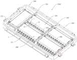
图8是本公开一种实施方式的动力电池包的立体结构示意图,其中隐去了电池包的上盖板。8 is a schematic three-dimensional structural diagram of a power battery pack according to an embodiment of the present disclosure, wherein the upper cover of the battery pack is hidden.
附图标记说明Description of reference numerals
1 排气孔 2 导气结构1
21 挡板 22 连接部21 Baffle 22 Connection
31 第一侧板 32 第二侧板31
33 第三侧板 34 第四侧板33
35 上盖板 36 下盖板35
4 导气口 100 单体电池4
110 防爆阀 200 电池模组110 Explosion-
300 托盘本体 310 底板300
320 边梁 330 纵向隔板320
340 横向隔板 1000 动力电池包340
具体实施方式Detailed ways
以下结合附图对本公开的具体实施方式进行详细说明。应当理解的是,此处所描述的具体实施方式仅用于说明和解释本公开,并不用于限制本公开。The specific embodiments of the present disclosure will be described in detail below with reference to the accompanying drawings. It should be understood that the specific embodiments described herein are only used to illustrate and explain the present disclosure, but not to limit the present disclosure.
在本公开中,在未作相反说明的情况下,使用的方位词如“上、下、左、右”通常与车辆正常行驶时的上、下、左、右的含义相同,“内、外”是相关零部件轮廓的内、外。In the present disclosure, unless otherwise stated, the directional words used such as "up, down, left and right" usually have the same meaning as up, down, left and right when the vehicle is running normally, "inside, outside" ” is the inside and outside of the associated component profile.
如图3至图8所示,根据本公开的一方面,提供了一种电池模组,该电池模组包括模组端盖和若干单体电池100,单体电池100上设置有防爆阀110,模组端盖上设置有若干与防爆阀110一一对应的排气孔1,至少部分排气孔1的外侧设置有导气结构2,导气结构2用于将气体沿与排气孔1的中心线成角度的方向引导,以避免气体直接作用到与排气孔1相对设置的其他零部件上。As shown in FIGS. 3 to 8 , according to an aspect of the present disclosure, a battery module is provided, the battery module includes a module end cover and a plurality of
通过上述技术方案,在单体电池100发生例如热失控异常时,气体依次流经模组端盖上的排气孔1和导气结构2,在导气结构2引导作用下,气体排出模组端盖外侧时,由于其流动方向与排气孔1的中心线呈角度设置,使得气体不会直接作用到与该电池模组200相对的其他零部件上,例如不会作用到其他电池模组上,从而不会导致其他电池模组中的单体电池的温度大幅升高,继而不会导致其他电池模组中的单体电池出现热失控。Through the above technical solution, when the
另外,相较于现有技术中在相对的两个电池模组200之间设置隔板(如图2所示的纵向隔板330)阻挡高温气体的技术方案,本公开的在模组端盖上设置导气结构2的方案至少具有以下优势:第一,由于设置有导气结构2,如图8所示,布置在动力电池包1000中时,相对设置的电池模组之间可省去隔板330,有利于动力电池包1000的轻量化,能降低成本,同时能够节约空间,便于其他零部件的布置;第二、由于每个排气孔1对应设置有一个导气结构2,即,每一个单体电池100对应有一个导气结构2,使得在导气过程中,同一个电池模组200中的每个单体电池100能够独立进行排气,并且由于没有隔板的阻隔作用,气体从导气结构2排出后能够快速扩散,相互之间不会产生影响。In addition, compared to the technical solution in the prior art in which a separator (the
可选地,导气结构2的气体引导方向大体垂直于所述排气孔1的中心线。这样,气体的流动方向大体垂直于排气孔1的中心线,保证气体不会直接作用到与该电池模组相对的其他电池模组上,从而最大程度地避免由于该单体电池的热失控而导致其他电池模组中的单体电池的温度短时间内大幅升高,减缓热失控的扩散,继而最大程度地减少由于该单体电池热失控而引起其他电池模组中的单体电池出现热失控现象的发生。Optionally, the gas guiding direction of the
进一步地,如图3至图5、图8所示,各个导气结构2的气体引导方向可均相同,以使得导气结构2呈规律布置,简化模组端盖的加工。在本公开的其他实施方式中,各个导气结构2的气体引导方向可以不同,只要能够顺利引导气体且不会对该电池模组以及其他电池模组中的单体电池造成影响即可。Further, as shown in FIG. 3 to FIG. 5 and FIG. 8 , the gas guiding directions of each
其中,导气结构2即可一体成型在模组端盖上,也可分别单独加工,并通过焊接等连接方式将导气结构2安装到模组端盖上。出于简化加工及装配工艺的角度,在本公开的一种实施方式中,导气结构2一体成型在模组端盖上。Wherein, the
在本公开中,导气结构2可具有任意适当的结构和形状。在一种实施方式中,如图3至图5所示,导气结构2包括挡板21和连接部22,连接部22位于挡板21与模组端盖之间,连接部22用于将挡板21连接在模组端盖上,挡板21与模组端盖之间留有排气间隙。具体地,如图5所示,挡板21可与防爆阀110相对设置,连接部22沿挡板21的一部分周缘延伸且与模组端盖相连,挡板21与模组端盖之间形成有供气流通过的导气口4。这样,由于挡板21的阻挡作用,迫使气体改变流动方向,并从导气口4中排出,流动方向大致与排气孔1的中心线垂直,能够有效避免气体直接作用到其他电池模组上。在本公开的其他可替换的实施方式中,导气结构2可构造为一端开放,另一端封闭且侧壁上开孔的导气罩,该导气罩的开放端连接于模组端盖并罩设住模组端盖上的排气孔1。In the present disclosure, the
需要说明的是,在本实施方式中,为了便于单体电池100上的防爆阀110开启,挡板21与模组端盖之间应该保证适合的距离,该距离的具体数值可根据防爆阀110类型及尺寸、防爆阀110的外端部凸出模组端盖的距离等实际情况而定,本公开对比不作限制。另外,防爆阀110可采用现有技术中采用的类型,这里不再赘述。It should be noted that, in this embodiment, in order to facilitate the opening of the explosion-
进一步地,如图3至图5所示,每个导气口4可位于对应的导气结构2的同一侧,以使每个导气结构2对气流的引导方向相同。这样,从位于后侧的导气结构2中导出的气体不会从位于前侧的导气结构2的导气口4回流至电池模组200内,能够进一步降低同一个电池模组200内的单体电池100之间热传递的概率。Further, as shown in FIGS. 3 to 5 , each
另外,如图5所示,挡板21可与排气孔1的形状及面积相同,连接部22沿排气孔1的一部分周缘延伸,以尽量减小导气结构2的尺寸,节约材料。其中,排气孔1可为圆孔,挡板21可为圆形挡板,以便于加工。In addition, as shown in FIG. 5 , the
在本公开中,模组端盖可为任意适当的结构和形状。如图3和图4所示,模组端盖可以包括构造成长方体结构的上盖板35、第一侧板31、第二侧板32、第三侧板33和第四侧板34,其中,排气孔1和导气结构2可设置在第一侧板31上。这样,在如图8所示的电池包中,根据本申请的电池模组,在左右方向上相邻两个电池模组之间不会产生相互影响。在本公开的其他可替换的实施方式中,根据单体电池100的防爆阀110的布置位置,排气孔1和导气结构2可设置在模组端盖的其他侧板上,如设置在上述实施方式中的上盖板35。这样,当上盖板35的上方还设置有其他结构,例如设置有电池包的上盖板时,由于设置有导气结构2,气体不会直接作用到该上盖板上,能够有效避免对该上盖板造成损害。In the present disclosure, the module end caps may be of any suitable structure and shape. As shown in FIGS. 3 and 4 , the module end cover may include an upper cover plate 35 , a
另外,在本公开其他实施方式中,模组端盖还可以包括下盖板36,此时,根据设计需要,可将排气孔1和导气结构2设置在下盖板36上。In addition, in other embodiments of the present disclosure, the module end cover may further include a
在本公开中,模组端盖具有的侧板的数量也可以根据需要设置,其数量可以为1、2、3、4等。In the present disclosure, the number of side plates provided by the module end cap can also be set as required, and the number can be 1, 2, 3, 4, etc.
为了能够抵抗高温气体的冲击且避免出现模组端盖发生起火情况,第一侧板31可为金属或阻燃性非金属,例如采用耐高温陶瓷或耐高温复合材料等。其中,如前文所述,导气结构2可一体成型在第一侧板31上。In order to be able to resist the impact of high temperature gas and prevent the module end cover from catching fire, the
另外,导气结构2的内壁上可设置耐高温膜,以更好地抵抗高温气体的冲击,保护导气结构2免受高温气体的破坏。In addition, a high temperature resistant film can be provided on the inner wall of the
另外,模组端盖的盖板和侧板的成型方式可为开模成型、板材冲压、焊接加工等。In addition, the forming methods of the cover plate and the side plate of the module end cover may be open-die forming, sheet stamping, welding processing, and the like.
在本公开中,导气结构2在第一侧板31上的位置以及排布方式可根据单体电池100的防爆阀110的位置而定。在一种实施方式中,如图3和图4所示,防爆阀110位于单体电池100的后端盖的一侧且相邻的单体电池100的防爆防110不在同一侧,此时,对应地,第一侧板31上形成有上下两排导气结构2。在本公开的另一种实施方式,如图6所示,防爆阀110位于单体电池100的后端盖的中部,多个单体电池100的防爆阀110位于同一高度,对应地,第一侧板31上形成有一排导气结构2。In the present disclosure, the position and arrangement of the
如图8所示,根据本公开的另一方面,提供一种动力电池包,该电池包包括电池托盘和上述的电池模组200,电池托盘包括托盘本体300和托盘盖板,托盘盖板与托盘本体300密封连接并共同形成用于容纳电池模组200的密闭空间,托盘本体300可以包括底板310、边梁320、以及若干隔板,边梁320设置在底板310的四周,若干隔板设置在底板310上并且将底板310分隔成若干用于放置电池模组200的区域。As shown in FIG. 8 , according to another aspect of the present disclosure, a power battery pack is provided. The battery pack includes a battery tray and the above-mentioned
其中,如图3、图4和图8所示,模组端盖可以包括构造成长方体结构的上盖板35、第一侧板31、第二侧板32、第三侧板33和第四侧板34,第一侧板31与第二侧板32相对设置,上盖板35与托盘盖板相对,排气孔1和导气结构2设置在模组端盖上,以防止电池模组200排出的气体影响到其他零部件,例如,可以将排气孔1和导气结构2设置在第一侧板31上。这样,在左右方向上相对的两个电池模组200中其中一者的模组端盖的第一侧板31与另一者的模组端盖的第二侧板32相对设置,在前后方向上相对的两个电池模组之间设置有横向隔板340。具体地,如图8所示,位于托盘本体300左侧的电池模组200的第一侧板31与位于托盘本体300右侧的电池模组200的第二侧板32相对设置,由于从左侧的电池模组200排出的气体的流动方向与第二侧板32平行,使得气体喷出后不会影响右侧的电池模组200。可选地,在本公开其他实施例中,模组端盖还可以包括下盖板36,下盖板36与托盘本体300的底板310相对设置。Wherein, as shown in FIGS. 3 , 4 and 8 , the module end cover may include an upper cover plate 35 , a
如图2所示,在现有技术的托盘中,隔板包括纵向隔板330和横向隔板340,并且在左右方向上相对的两个电池模组200之间设置有纵向隔板330,以阻挡高温气体,在前后方向上相对的两个电池模组200之间设置有横向隔板340。如图8所示,在本公开提供的托盘中,省去了纵向隔板330。相较于现有技术的托盘,本公开的托盘结构得以简化,电池模组200摆放更加灵活,空间利用率增加,成本降低。而且单体电池100的气体排出电池模组200后,气体会沿一个方向排出,气体不会滞留在失控的单体电池100附近,可迅速扩散,因而热失控单体电池100周围温度不会急剧升高,有助减缓热扩散过程。As shown in FIG. 2 , in the prior art tray, the separator includes a
根据本公开的又一方面,提供一种车辆,该车辆包括上述的动力电池包1000。本公开提供的电池包安全性能大大提高。According to yet another aspect of the present disclosure, a vehicle is provided, which includes the above-mentioned
以上结合附图详细描述了本公开的优选实施方式,但是,本公开并不限于上述实施方式中的具体细节,在本公开的技术构思范围内,可以对本公开的技术方案进行多种简单变型,这些简单变型均属于本公开的保护范围。The preferred embodiments of the present disclosure have been described above in detail with reference to the accompanying drawings. However, the present disclosure is not limited to the specific details of the above-mentioned embodiments. Various simple modifications can be made to the technical solutions of the present disclosure within the scope of the technical concept of the present disclosure. These simple modifications all fall within the protection scope of the present disclosure.
另外需要说明的是,在上述具体实施方式中所描述的各个具体技术特征,在不矛盾的情况下,可以通过任何合适的方式进行组合,为了避免不必要的重复,本公开对各种可能的组合方式不再另行说明。In addition, it should be noted that the various specific technical features described in the above-mentioned specific embodiments can be combined in any suitable manner unless they are inconsistent. In order to avoid unnecessary repetition, the present disclosure provides The combination method will not be specified otherwise.
此外,本公开的各种不同的实施方式之间也可以进行任意组合,只要其不违背本公开的思想,其同样应当视为本公开所公开的内容。In addition, the various embodiments of the present disclosure can also be arbitrarily combined, as long as they do not violate the spirit of the present disclosure, they should also be regarded as the contents disclosed in the present disclosure.
Claims (13)
Priority Applications (1)
| Application Number | Priority Date | Filing Date | Title |
|---|---|---|---|
| CN201910178054.XACN111668423B (en) | 2019-03-08 | 2019-03-08 | Battery module, power battery package and vehicle |
Applications Claiming Priority (1)
| Application Number | Priority Date | Filing Date | Title |
|---|---|---|---|
| CN201910178054.XACN111668423B (en) | 2019-03-08 | 2019-03-08 | Battery module, power battery package and vehicle |
Publications (2)
| Publication Number | Publication Date |
|---|---|
| CN111668423Atrue CN111668423A (en) | 2020-09-15 |
| CN111668423B CN111668423B (en) | 2021-12-07 |
Family
ID=72382054
Family Applications (1)
| Application Number | Title | Priority Date | Filing Date |
|---|---|---|---|
| CN201910178054.XAActiveCN111668423B (en) | 2019-03-08 | 2019-03-08 | Battery module, power battery package and vehicle |
Country Status (1)
| Country | Link |
|---|---|
| CN (1) | CN111668423B (en) |
Cited By (5)
| Publication number | Priority date | Publication date | Assignee | Title |
|---|---|---|---|---|
| CN113113713A (en)* | 2021-04-08 | 2021-07-13 | 中国第一汽车股份有限公司 | Power battery assembly and vehicle |
| CN113517514A (en)* | 2021-04-22 | 2021-10-19 | 远景动力技术(江苏)有限公司 | Directional exhaust battery module |
| WO2022143422A1 (en)* | 2020-12-29 | 2022-07-07 | 蜂巢能源科技股份有限公司 | Battery module, power battery and vehicle |
| CN116171504A (en)* | 2021-01-22 | 2023-05-26 | 株式会社Lg新能源 | Battery module and battery pack including the battery module |
| WO2024093026A1 (en)* | 2022-10-31 | 2024-05-10 | 宁德时代新能源科技股份有限公司 | Isolation plate, isolation plate assembly, battery module, battery pack, and electric device |
Citations (5)
| Publication number | Priority date | Publication date | Assignee | Title |
|---|---|---|---|---|
| US20090142650A1 (en)* | 2007-11-28 | 2009-06-04 | Wataru Okada | Battery system |
| CN102468463A (en)* | 2010-11-08 | 2012-05-23 | Sb锂摩托有限公司 | Battery module |
| WO2012147150A1 (en)* | 2011-04-25 | 2012-11-01 | 日立ビークルエナジー株式会社 | Battery assembly and single cell |
| CN203415658U (en)* | 2013-06-07 | 2014-01-29 | 宁德新能源科技有限公司 | Li-ion secondary battery and safety protecting device thereof |
| CN109417142A (en)* | 2016-07-11 | 2019-03-01 | 松下知识产权经营株式会社 | Battery module |
- 2019
- 2019-03-08CNCN201910178054.XApatent/CN111668423B/enactiveActive
Patent Citations (5)
| Publication number | Priority date | Publication date | Assignee | Title |
|---|---|---|---|---|
| US20090142650A1 (en)* | 2007-11-28 | 2009-06-04 | Wataru Okada | Battery system |
| CN102468463A (en)* | 2010-11-08 | 2012-05-23 | Sb锂摩托有限公司 | Battery module |
| WO2012147150A1 (en)* | 2011-04-25 | 2012-11-01 | 日立ビークルエナジー株式会社 | Battery assembly and single cell |
| CN203415658U (en)* | 2013-06-07 | 2014-01-29 | 宁德新能源科技有限公司 | Li-ion secondary battery and safety protecting device thereof |
| CN109417142A (en)* | 2016-07-11 | 2019-03-01 | 松下知识产权经营株式会社 | Battery module |
Cited By (5)
| Publication number | Priority date | Publication date | Assignee | Title |
|---|---|---|---|---|
| WO2022143422A1 (en)* | 2020-12-29 | 2022-07-07 | 蜂巢能源科技股份有限公司 | Battery module, power battery and vehicle |
| CN116171504A (en)* | 2021-01-22 | 2023-05-26 | 株式会社Lg新能源 | Battery module and battery pack including the battery module |
| CN113113713A (en)* | 2021-04-08 | 2021-07-13 | 中国第一汽车股份有限公司 | Power battery assembly and vehicle |
| CN113517514A (en)* | 2021-04-22 | 2021-10-19 | 远景动力技术(江苏)有限公司 | Directional exhaust battery module |
| WO2024093026A1 (en)* | 2022-10-31 | 2024-05-10 | 宁德时代新能源科技股份有限公司 | Isolation plate, isolation plate assembly, battery module, battery pack, and electric device |
Also Published As
| Publication number | Publication date |
|---|---|
| CN111668423B (en) | 2021-12-07 |
Similar Documents
| Publication | Publication Date | Title |
|---|---|---|
| CN111668423A (en) | Battery modules, power battery packs and vehicles | |
| US20220123423A1 (en) | Battery pack and apparatus | |
| EP3796412B1 (en) | Battery pack | |
| JP7731955B2 (en) | Power battery pack and vehicle | |
| EP3905368B1 (en) | Battery tray and power battery pack | |
| CN111668408B (en) | Battery trays, power battery packs and vehicles | |
| US12334582B2 (en) | Upper cover assembly and battery pack | |
| JP7605971B2 (en) | Battery pack with improved gas venting path | |
| US20220077539A1 (en) | Battery tray and power battery pack | |
| CN113966565A (en) | Battery packs and transportation equipment | |
| CN111668410A (en) | Power battery pack and vehicle | |
| CN111668409A (en) | Battery trays, power battery packs and vehicles | |
| CN215816252U (en) | battery system | |
| JP2022553242A (en) | battery pack and vehicle | |
| CN209691818U (en) | Energy storage device | |
| CN209496936U (en) | battery module | |
| JP2024543919A (en) | Battery pack with double top cover with vent gas exhaust passage | |
| JP2024538750A (en) | Battery pack | |
| CN116093534B (en) | Battery pack, power battery system and vehicle | |
| CN115764192A (en) | battery module | |
| CN220324579U (en) | Support components for battery packs, battery packs and electrical devices | |
| CN219123404U (en) | Battery pack structure with thermal safety and directional exhaust | |
| CN221486724U (en) | Explosion-proof valve for battery pack and battery pack | |
| CN221961160U (en) | Battery Pack | |
| CN120497573A (en) | Box assembly, battery pack and carrier |
Legal Events
| Date | Code | Title | Description |
|---|---|---|---|
| PB01 | Publication | ||
| PB01 | Publication | ||
| SE01 | Entry into force of request for substantive examination | ||
| SE01 | Entry into force of request for substantive examination | ||
| GR01 | Patent grant | ||
| GR01 | Patent grant |