CN111658955B - Improved medical cannula - Google Patents
Improved medical cannulaDownload PDFInfo
- Publication number
- CN111658955B CN111658955BCN202010605098.9ACN202010605098ACN111658955BCN 111658955 BCN111658955 BCN 111658955BCN 202010605098 ACN202010605098 ACN 202010605098ACN 111658955 BCN111658955 BCN 111658955B
- Authority
- CN
- China
- Prior art keywords
- piece
- deformation
- elastic
- sub
- tube body
- Prior art date
- Legal status (The legal status is an assumption and is not a legal conclusion. Google has not performed a legal analysis and makes no representation as to the accuracy of the status listed.)
- Expired - Fee Related
Links
Images


Classifications
- A—HUMAN NECESSITIES
- A61—MEDICAL OR VETERINARY SCIENCE; HYGIENE
- A61M—DEVICES FOR INTRODUCING MEDIA INTO, OR ONTO, THE BODY; DEVICES FOR TRANSDUCING BODY MEDIA OR FOR TAKING MEDIA FROM THE BODY; DEVICES FOR PRODUCING OR ENDING SLEEP OR STUPOR
- A61M25/00—Catheters; Hollow probes
- A61M25/0021—Catheters; Hollow probes characterised by the form of the tubing
- A—HUMAN NECESSITIES
- A61—MEDICAL OR VETERINARY SCIENCE; HYGIENE
- A61M—DEVICES FOR INTRODUCING MEDIA INTO, OR ONTO, THE BODY; DEVICES FOR TRANSDUCING BODY MEDIA OR FOR TAKING MEDIA FROM THE BODY; DEVICES FOR PRODUCING OR ENDING SLEEP OR STUPOR
- A61M25/00—Catheters; Hollow probes
- A61M25/0043—Catheters; Hollow probes characterised by structural features
- A61M25/005—Catheters; Hollow probes characterised by structural features with embedded materials for reinforcement, e.g. wires, coils, braids
- A61M25/0052—Localized reinforcement, e.g. where only a specific part of the catheter is reinforced, for rapid exchange guidewire port
- A—HUMAN NECESSITIES
- A61—MEDICAL OR VETERINARY SCIENCE; HYGIENE
- A61M—DEVICES FOR INTRODUCING MEDIA INTO, OR ONTO, THE BODY; DEVICES FOR TRANSDUCING BODY MEDIA OR FOR TAKING MEDIA FROM THE BODY; DEVICES FOR PRODUCING OR ENDING SLEEP OR STUPOR
- A61M25/00—Catheters; Hollow probes
- A61M25/0043—Catheters; Hollow probes characterised by structural features
- A61M25/0054—Catheters; Hollow probes characterised by structural features with regions for increasing flexibility
Landscapes
- Health & Medical Sciences (AREA)
- Life Sciences & Earth Sciences (AREA)
- Biophysics (AREA)
- Pulmonology (AREA)
- Engineering & Computer Science (AREA)
- Anesthesiology (AREA)
- Biomedical Technology (AREA)
- Heart & Thoracic Surgery (AREA)
- Hematology (AREA)
- Animal Behavior & Ethology (AREA)
- General Health & Medical Sciences (AREA)
- Public Health (AREA)
- Veterinary Medicine (AREA)
- External Artificial Organs (AREA)
Abstract
Translated fromChinese
Description
Translated fromChinese技术领域technical field
本发明涉及医疗器械技术领域,具体地,涉及一种改进型医用插管。The present invention relates to the technical field of medical devices, in particular to an improved medical cannula.
背景技术Background technique
医用插管(包括动脉插管、静脉插管、股动脉插管及股静脉插管等)经常使用于各种需要体外循环手术中,目前传统的插管主要包括管套、设置于管套内的弹簧以及支撑片,此外,为了增加引流效果,插管一般通过开设侧向引流孔(或引流槽)来实现;引流孔(或引流槽)主要是在支撑片所在区域进行开设,由支撑片为引流孔提供支撑;人体内的血管是蜿蜒曲行的,插管需要顺着血管插入,现有的插管中,支撑片所在位置由于其结构特性,其弯折性能较差,灵活性不佳,不便于医生的操作,严重时还会损伤人体血管。Medical intubation (including arterial intubation, venous intubation, femoral artery intubation and femoral vein intubation, etc.) are often used in various surgeries that require cardiopulmonary bypass. In addition, in order to increase the drainage effect, intubation is generally realized by opening lateral drainage holes (or drainage grooves); the drainage holes (or drainage grooves) are mainly opened in the area where the support sheet is located, and the Provide support for the drainage hole; the blood vessels in the human body are meandering, and the cannula needs to be inserted along the blood vessels. In the existing cannula, the position of the support piece has poor bending performance and flexibility due to its structural characteristics. If it is not good, it is inconvenient for doctors to operate, and in severe cases, it will damage the blood vessels of the human body.
此外,在医用插管的生产制作过程中,由于需要将弹簧及支撑片套设于插管的内管中,而两者之间的间隙很小,目前常见的薄壁支撑片弹性变形性能不佳,导致生产过程中支撑片套设困难,定位不够准确,生产效率不高。In addition, in the production process of the medical cannula, since the spring and the support piece need to be sleeved in the inner tube of the cannula, and the gap between the two is very small, the elastic deformation performance of the currently common thin-wall support piece is not good. In the production process, it is difficult to set the support piece, the positioning is not accurate enough, and the production efficiency is not high.
发明内容SUMMARY OF THE INVENTION
针对现有技术的不足,本发明提供一种改进型医用插管。In view of the deficiencies of the prior art, the present invention provides an improved medical cannula.
本发明公开的一种改进型医用插管,包括:管体、弹性支撑体以及引流孔,弹性支撑体设置于管体内,弹性支撑体包括弹性件及变形件,弹性件抵接变形件,变形件沿管体径向开设有变形孔,引流孔开设于变形件所在的管体区段(即引流孔与变形件位于管体同一区域)。An improved medical intubation tube disclosed by the present invention comprises: a tube body, an elastic support body and a drainage hole, the elastic support body is arranged in the tube body, and the elastic support body includes an elastic part and a deformation part, the elastic part abuts the deformation part, and deforms A deformation hole is opened in the radial direction of the pipe body, and the drainage hole is opened in the section of the pipe body where the deformation element is located (that is, the drainage hole and the deformation element are located in the same area of the pipe body).
根据本发明的一实施方式,弹性支撑体采用具有记忆功能的金属如镍钛合金制成。通过对弹性支撑件的内周施加扩张力或外周施加拉伸力使其内径增大,便于生产过程中进行弹性支撑件的套设,套设到位后松开即可利用其记忆功能回复至原状实现固定。According to an embodiment of the present invention, the elastic support body is made of a metal with memory function, such as nickel-titanium alloy. By applying an expansion force to the inner circumference of the elastic support or a tensile force to the outer circumference to increase the inner diameter, it is convenient to set the elastic support in the production process. Implement fixed.
根据本发明的一实施方式,变形件包括端部变形片及中部变形片,端部变形片设置于管体远端,中部变形片设置于管体中部。According to an embodiment of the present invention, the deformation member includes an end deformation piece and a middle deformation piece, the end deformation piece is disposed at the distal end of the pipe body, and the middle deformation piece is disposed in the middle of the pipe body.
根据本发明的一实施方式,端部变形片包括依序连接的第一连接子片、第一支撑变形子片及第二连接子片,第二连接子片抵接弹性件。According to an embodiment of the present invention, the end deforming piece includes a first connecting sub-piece, a first supporting deformation sub-piece and a second connecting sub-piece which are connected in sequence, and the second connecting sub-piece abuts against the elastic member.
根据本发明的一实施方式,第一连接子片、第一支撑变形子片及第二连接子片为一体成型或者组装成型。According to an embodiment of the present invention, the first connecting sub-piece, the first supporting and deforming sub-piece, and the second connecting sub-piece are integrally formed or assembled.
根据本发明的一实施方式,第一支撑变形子片开设有第一支撑孔,引流孔与第一支撑孔位于管体同一区域。According to an embodiment of the present invention, the first support deformation sub-piece is provided with a first support hole, and the drainage hole and the first support hole are located in the same area of the pipe body.
根据本发明的一实施方式,中部变形片包括依序连接的第三连接子片、第二支撑变形子片及第四连接子片,第三连接子片及第四连接子片均抵接弹性件。According to an embodiment of the present invention, the middle deformation piece includes a third connecting sub-piece, a second supporting deformation sub-piece, and a fourth connecting sub-piece that are connected in sequence, and the third connecting sub-piece and the fourth connecting sub-piece abut elastically pieces.
根据本发明的一实施方式,第二支撑变形子片开设有第二支撑孔,第二支撑孔与引流孔位于管体同一区域。According to an embodiment of the present invention, the second supporting deformation sub-piece is provided with a second supporting hole, and the second supporting hole and the drainage hole are located in the same area of the pipe body.
根据本发明的一实施方式,管体包括依序连接的管身、变径接头及连接头;管身包括内管及套设于内管的外管,弹性件及变形件均套设于内管。According to an embodiment of the present invention, the pipe body includes a pipe body, a reducing joint and a connecting head which are connected in sequence; the pipe body includes an inner pipe and an outer pipe sleeved on the inner pipe, and the elastic part and the deforming part are sleeved inside the inner pipe. Tube.
根据本发明的一实施方式,弹性件为弹簧。According to an embodiment of the present invention, the elastic member is a spring.
根据本发明的一实施方式,弹性件的截面为圆形或者矩形。According to an embodiment of the present invention, the cross section of the elastic member is circular or rectangular.
根据本发明的一实施方式,弹性件和/或变形件采用具有记忆功能的金属制成。According to an embodiment of the present invention, the elastic member and/or the deformation member are made of metal with memory function.
本发明的有益效果在于,通过管体、弹性支撑体及引流孔的配合使用,弹性件为管体提供支撑,变形件为引流孔提供支撑,防止使用过程中管体出现塌陷现象,导致血液流通受阻,同时,变形件上的变形孔设置,使得变形件存在变形空间,有利于提高管体的弯折性能,增加灵活性,使得管体能更好的沿着血管前行,且还能降低管体损坏血管的风险,更有利于医生的操控。弹性支撑体采用具有记忆功能的金属如镍钛合金制成,具有良好的弹性变形性能,在生产过程中先将其撑开套设入插管内管,到位后再利用其记忆功能复原并固定在内管上,从而有效解决了常规产品套设困难,定位不够准确,生产效率不高的问题。The beneficial effect of the present invention is that, through the cooperative use of the tube body, the elastic support body and the drainage hole, the elastic member provides support for the tube body, and the deformed member provides support for the drainage hole, so as to prevent the tube body from collapsing during use, resulting in blood circulation At the same time, the deformation holes on the deforming part are arranged, so that there is a deformation space in the deforming part, which is beneficial to improve the bending performance of the tube body and increase the flexibility, so that the tube body can better move along the blood vessels, and can also reduce the tube body. The risk of body damage to blood vessels is more conducive to the doctor's control. The elastic support body is made of metal with memory function such as nickel-titanium alloy, which has good elastic deformation performance. During the production process, it is first stretched and sleeved into the inner tube of the cannula, and then restored and fixed by its memory function after it is in place. On the inner tube, the problems of difficulty in setting conventional products, inaccurate positioning and low production efficiency are effectively solved.
附图说明Description of drawings
此处所说明的附图用来提供对本申请的进一步理解,构成本申请的一部分,本申请的示意性实施例及其说明用于解释本申请,并不构成对本申请的不当限定。在附图中:The drawings described herein are used to provide further understanding of the present application and constitute a part of the present application. The schematic embodiments and descriptions of the present application are used to explain the present application and do not constitute an improper limitation of the present application. In the attached image:
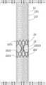
图1为实施例中改进型医用插管的立体结构图;1 is a three-dimensional structural view of an improved medical cannula in an embodiment;
图2为实施例中改进型医用插管的结构图;Fig. 2 is the structural diagram of the improved medical cannula in the embodiment;
图3为实施例中改进型医用插管的另一结构图;Fig. 3 is another structural diagram of the improved medical cannula in the embodiment;
图4为实施例中端部变形片的立体结构图;Fig. 4 is the three-dimensional structure diagram of the end deformation piece in the embodiment;
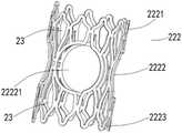
图5为实施例中中部变形片的立体结构图。FIG. 5 is a three-dimensional structural view of the middle deformation piece in the embodiment.
附图标记说明Description of reference numerals
1-管体;11-管身;111-内管;112-外管;12-变径接头;13-连接头;1-pipe body; 11-pipe body; 111-inner pipe; 112-outer pipe; 12-reducer joint; 13-connector;
2-弹性支撑体;21-弹性件;22-变形件;221-端部变形片;2211-第一连接子片;2212-第一支撑变形子片;22121-第一支撑孔;2213-第二连接子片;222-中部变形片;2221-第三连接子片;2222-第二支撑变形子片;22221-第二支撑孔;2223-第四连接子片;23-变形孔;2- elastic support body; 21- elastic part; 22- deformation part; 221- end deformation piece; 2211- first connecting sub-piece; 2212- first supporting deformation sub-piece; 22121- first supporting hole; Two connecting sub-pieces; 222-the middle deformation piece; 2221-the third connecting sub-piece; 2222-the second supporting deformation sub-piece; 22221-the second supporting hole; 2223-the fourth connecting sub-piece; 23-deforming hole;
3-引流孔。3- Drainage hole.
具体实施方式Detailed ways
以下将以图式揭露本发明的多个实施方式,为明确说明起见,许多实务上的细节将在以下叙述中一并说明。然而,应了解到,这些实务上的细节不应用以限制本发明。也就是说,在本发明的部分实施方式中,这些实务上的细节是非必要的。此外,为简化图式起见,一些习知惯用的结构与组件在图式中将以简单的示意的方式绘示之。Various embodiments of the present invention will be disclosed in the drawings below, and for the sake of clarity, many practical details will be described together in the following description. It should be understood, however, that these practical details should not be used to limit the invention. That is, in some embodiments of the invention, these practical details are unnecessary. In addition, for the purpose of simplifying the drawings, some well-known structures and components will be shown in a simple schematic manner in the drawings.
另外,在本发明中如涉及“第一”、“第二”等的描述仅用于描述目的,并非特别指称次序或顺位的意思,亦非用以限定本发明,其仅仅是为了区别以相同技术用语描述的组件或操作而已,而不能理解为指示或暗示其相对重要性或者隐含指明所指示的技术特征的数量。由此,限定有“第一”、“第二”的特征可以明示或者隐含地包括至少一个该特征。另外,各个实施例之间的技术方案可以相互结合,但是必须是以本领域普通技术人员能够实现为基础,当技术方案的结合出现相互矛盾或无法实现时应当认为这种技术方案的结合不存在,也不在本发明要求的保护范围之内。In addition, descriptions such as “first”, “second”, etc. in the present invention are only for the purpose of description, and do not refer to the meaning of order or sequence, nor are they used to limit the present invention. The components or operations are described by the same technical terms, and should not be construed as indicating or implying their relative importance or implying the quantity of the indicated technical features. Thus, a feature delimited with "first", "second" may expressly or implicitly include at least one of that feature. In addition, the technical solutions between the various embodiments can be combined with each other, but must be based on the realization by those of ordinary skill in the art. When the combination of technical solutions is contradictory or cannot be realized, it should be considered that the combination of technical solutions does not exist. , is not within the scope of protection required by the present invention.
需要说明的是,在本发明中,“近端”和“远端”是从使用该医疗器械的医生角度来看相对于彼此的元件或动作的相对方位、相对位置、方向,尽管“近端”和“远端”并非是限制性的,但是“近端”通常指该医疗器械在正常操作过程中靠近医生的一端,而“远端”通常是指首先进入患者体内的一端。It should be noted that, in the present invention, "proximal end" and "distal end" are relative orientations, relative positions, and directions of elements or actions relative to each other from the perspective of the doctor using the medical device, although "proximal end" " and "distal" are not limiting, but "proximal" generally refers to the end of the medical device that is closest to the physician during normal operation, and "distal" generally refers to the end that first enters the patient.
如图1-3所示,图1为实施例中改进型医用插管的立体结构图;图2为实施例中改进型医用插管的结构图;图3为实施例中改进型医用插管的另一结构图。本发明的改进型医用插管包括管体1、弹性支撑体2及引流孔3,弹性支撑体2设置于管体1内,引流孔3贯穿开设于管体1。弹性支撑体2可采用具有记忆功能的金属如镍钛合金制成,具有良好的弹性变形性能。弹性支撑体2包括弹性件21及变形件22,弹性件21及变形件22均套设于管体1,且弹性件21与变形件22相互抵接,引流孔3开设于变形件22所在的管体1区段(即引流孔3与变形件22位于管体1的同一区域)。具体的,弹性件21和/或变形件22采用具有记忆功能的金属制成,具有良好的弹性变形性能。变形件22沿管体1的径向上设有变形孔23。此外,当变形孔23开设在管体1远端的端部时,由端部入口进行变形件22的套设不需要特别大的弹性变形,因此该端部段的变形孔23也可轴向开设。弹性件21为管体1提供支撑,使得管体1具备一定的纵向刚性和弯折性,不易塌陷和折瘪,变形件22为引流孔3提供支撑,同时,变形件22上的变形孔23在使用过程中为其提供变形空间,即当管体1进行折弯时,由于变形孔23的设置,整个变形件22可随管体1进行相应的弯曲,并且保持与弹性件21之间的作用力,便于医生继续操控管体1。As shown in Figures 1-3, Figure 1 is a three-dimensional structural diagram of the improved medical cannula in the embodiment; Figure 2 is a structural diagram of the improved medical cannula in the embodiment; Figure 3 is the improved medical cannula in the embodiment. Another structure diagram of . The improved medical cannula of the present invention includes a
优选地,管体1包括管身11、变径接头12及连接头13,管身11、变径接头12及连接头13依序连接,弹性件21及变形件22均套设于管身11。具体应用时,管身11与变径接头12的夹角为钝角或平角,管身11的远端与管身11的中部所成的夹角也为钝角或者平角,便于管体1插入人体后,在不同区段的过渡更为顺畅,防止对人体组织造成损害。变径接头12的外径大于管身11的外径,便于使用时将人体上的开口撑大至所需的程度,连接头13主要是将另一结构件与管身11、变径接头12连接。Preferably, the
进一步优选地,管身11包括内管111及外管112,外管112套设于内管111,弹性件21及变形件22均套设于内管111,且弹性件21及变形件22位于内管111与外管112之间;在生产过程中先将弹性件21、变形件22撑开套设于内管111,到位后再利用其记忆功能复原并固定在内管111上,最后将外管112套设于弹性件21及变形件22上,从而有效解决了常规产品套设困难,定位不够准确,生产效率不高的问题。引流孔3贯穿内管111及外管112。具体的,内管111及外管112均由TPU(Thermoplastic polyurethanes,热塑性聚氨酯弹性体橡胶)制成,提高其耐磨性能、透明性能及弹性性能。Further preferably, the
具体应用时,弹性件21为弹簧,弹性件21的截面可以为圆形或者方形。In a specific application, the
再一并参照图4所示,图4为实施例中端部变形片221的立体结构图。优选地,变形件22包括端部变形片221及中部变形片222,端部变形片221位于管身11的远端,中部变形片222位于管身11的中部,端部变形片221及中部变形片222均开设有引流孔3。具体应用时,端部变形片221包括第一连接子片2211、第一支撑变形子片2212及第二连接子片2213,第一连接子片2211、第二连接子片2213分别设置于第一支撑变形子片2212两端,且第二连接子片2213抵接弹性件21,第一连接子片2211、第一支撑变形子片2212及第二连接子片2213上均设有多个变形孔23,且多个变形孔23沿三者的横向分布,横向是指与管体1径向相平行的方向,Referring again to FIG. 4 , FIG. 4 is a three-dimensional structural view of the
在生产时,通过对端部变形片221的内周施加扩张力或外周施加拉伸力使其内径增大,第一连接子片2211与第一支撑变形子片2212之间的连接部位(图中未标识)、第一支撑变形子片2212与第二连接子片2213的连接部位(图中未标识)被拉伸,相对应的多个变形孔23为端部变形片221提供了变形空间,使端部变形片221可方便的套设入内管111,到位后再复原至原形状并固定在内管111上。During production, the inner diameter of the end
由于变形孔23的设置,以及第一连接子片2211、第一支撑变形子片2212及第二连接子片2213呈网状结构,使成型后的管体1在使用时的折弯性能以及回弹性能上都得到大幅度提升。具体的,第二连接子片2213与弹性件21抵接处设有凸出部(图中未标识),由于弹性件21在结束区段会存在空白处,该凸出部主要用于填补该空白处,也就是说第二连接子片2213与弹性件21连接处的纵截面呈阶梯状;使得管体1整体受力均匀,也能防止该空白处被挤压变形,缩小血液通道。第一连接子片2211位于管身11的远端,由于最先进入人体的管身11的远端,初始受到的挤压力是最大的,故需要管体1具备更为强劲的支撑力,因此,第一连接子片2211的展开面积大于第二连接子片2213。本实施例中第一连接子片2211、第一支撑变形子片2212及第二连接子片2213可以是一体成型,也可以是组装而成;第一连接子片2211、第一支撑变形子片2212及第二连接子片2213可选用具有一定弹性及记忆功能的材料,例如镍钛合金,既能提高其折弯性能、回弹性能,还能方便套入到内管111中,使得安装变得快捷,进而提高装配效率;三者的加工工艺可以是激光雕刻成型,也可以是冲压成型。Due to the arrangement of the
进一步优选地,第一支撑变形子片2212开设有第一支撑孔22121,引流孔3与第一支撑孔22121位于管体1的同一区域,且第一支撑孔22121的直径大于引流孔3的直径,有利于提高引流孔3的支撑力,防止使用过程中引流孔3周围的管体1发生塌陷的现象。具体应用时,第一支撑孔22121的数量为多个,多个第一支撑孔22121环绕第一支撑变形子片2212设置,且多个第一支撑孔22121两两对称设置,便于后续对引流孔3的开设,即开设引流孔3时,可从管体1的一侧直接开设至另一侧,减少加工步骤,缩短加工时间,提高加工效率。Further preferably, the first supporting
再一并参照图5所示,图5为实施例中中部变形片222的立体结构图。优选地,中部变形片222包括第三连接子片2221、第二支撑变形子片2222及第四连接子片2223,第二支撑变形子片2222的两端分别连接第三连接子片2221及第四连接子片2223,同时,第三连接子片2221及第四连接子片2223均抵接弹性件21;第三连接子片2221、第二支撑变形子片2222及第四连接子片2223上均开设有多个变形孔23,且多个变形孔23沿三者的横向分布。中部变形片222的生产过程与端部变形片221相同,在此不再赘述。具体应用时,第三连接子片2221及第四连接子片2223均设有凸起部,其作用与第二连接子片2213中的凸起部相同。具体的,第三连接子片2221与第四连接子片2223的结构可相同,也可不相同。实际应用时,可根据管身11长度或者使用需求设置多个中部变形片222,增强管体1的折弯性能。本实施例中第三连接子片2221、第二支撑变形子片2222及第四连接子片2223可以是一体成型,也可以是组装而成;第三连接子片2221、第二支撑变形子片2222及第四连接子片2223可选用具有一定弹性及记忆功能的材料,例如镍钛合金,既能提高其折弯性能,还能方便套入到内管111中,使得安装变得快捷,进而提高装配效率;三者的加工工艺可以是激光雕刻成型,也可以是冲压成型。Referring again to FIG. 5 , FIG. 5 is a three-dimensional structural diagram of the
进一步优选地,第二支撑变形子片2222开设有第二支撑孔22221,引流孔3与第二支撑孔22221位于管体1的同一区域,且第二支撑孔22221的直径大于引流孔3的直径,有利于提高引流孔3的支撑力,防止使用过程中引流孔3周围的管体1发生塌陷的现象。具体应用时,第二支撑孔22221的数量为多个,多个第二支撑孔22221环绕第二支撑变形子片2222设置,且多个第二支撑孔22221两两对称设置,便于后续对引流孔3的开设,即开设引流孔3时,可从管体1的一侧直接开设至另一侧,减少加工步骤,缩短加工时间,提高加工效率。本实施例中,第一支撑孔22121与第二支撑孔22221相同,当然,使用过程中,第一支撑孔22121与第二支撑孔22221的结构也可以不相同,只要其直径大于引流孔3即可。Further preferably, the second supporting
改进型医用插管装配时,先将多个弹性件21及多个中部变形片222间隔套入内管111,在内管111的远端套入端部变形片221,再将外管112套入并通过热塑工艺将其合而为一,而后在第一支撑孔22121、第二支撑孔22221对应的内管111及外管112位置进行开设引流孔3,最后将变径接头12及连接头13对应组装。When assembling the improved medical cannula, firstly insert a plurality of
综上,通过管体、弹性支撑体及引流孔的配合使用,弹性件为管体提供支撑,变形件为引流孔提供支撑,防止使用过程中管体出现塌陷现象,导致血液流通受阻,同时,变形件上的变形孔设置,使得变形件存在变形空间,有利于提高管体的弯折性能,增加灵活性,使得管体能更好的沿着血管前行,且还能降低管体损坏血管的风险,更有利于医生的操控。弹性支撑体采用具有记忆功能的金属如镍钛合金制成,具有良好的弹性变形性能,在生产过程中先将其撑开套设入插管内管,到位后再利用其记忆功能复原并固定在内管上,从而有效解决了常规医用插管产品套设困难,定位不够准确,生产效率不高的问题。In summary, through the combined use of the tube body, the elastic support body and the drainage hole, the elastic piece provides support for the tube body, and the deformed piece provides support for the drainage hole, preventing the tube body from collapsing during use, resulting in obstruction of blood flow. The deformation holes on the deforming part are arranged, so that there is a deformation space in the deforming part, which is beneficial to improve the bending performance of the tube body, increase the flexibility, make the tube body better move along the blood vessels, and also reduce the damage of the tube body to the blood vessels. Risk, more conducive to the doctor's control. The elastic support body is made of metal with memory function such as nickel-titanium alloy, which has good elastic deformation performance. During the production process, it is first stretched and sleeved into the inner tube of the cannula, and then restored and fixed by its memory function after it is in place. On the inner tube, the problems of difficulty in setting conventional medical intubation products, inaccurate positioning and low production efficiency are effectively solved.
上所述仅为本发明的实施方式而已,并不用于限制本发明。对于本领域技术人员来说,本发明可以有各种更改和变化。凡在本发明的精神和原理的内所作的任何修改、等同替换、改进等,均应包括在本发明的权利要求范围之内。The above description is merely an embodiment of the present invention, and is not intended to limit the present invention. Various modifications and variations of the present invention are possible for those skilled in the art. Any modification, equivalent replacement, improvement, etc. made within the spirit and principle of the present invention shall be included within the scope of the claims of the present invention.
Claims (7)
Priority Applications (1)
| Application Number | Priority Date | Filing Date | Title |
|---|---|---|---|
| CN202010605098.9ACN111658955B (en) | 2020-06-29 | 2020-06-29 | Improved medical cannula |
Applications Claiming Priority (1)
| Application Number | Priority Date | Filing Date | Title |
|---|---|---|---|
| CN202010605098.9ACN111658955B (en) | 2020-06-29 | 2020-06-29 | Improved medical cannula |
Publications (2)
| Publication Number | Publication Date |
|---|---|
| CN111658955A CN111658955A (en) | 2020-09-15 |
| CN111658955Btrue CN111658955B (en) | 2022-06-14 |
Family
ID=72390271
Family Applications (1)
| Application Number | Title | Priority Date | Filing Date |
|---|---|---|---|
| CN202010605098.9AExpired - Fee RelatedCN111658955B (en) | 2020-06-29 | 2020-06-29 | Improved medical cannula |
Country Status (1)
| Country | Link |
|---|---|
| CN (1) | CN111658955B (en) |
Citations (5)
| Publication number | Priority date | Publication date | Assignee | Title |
|---|---|---|---|---|
| JP2012503534A (en)* | 2008-09-25 | 2012-02-09 | アドバンスド バイファケーション システムズ, インコーポレイテッド | Partially crimped stent |
| CN103037815A (en)* | 2010-03-24 | 2013-04-10 | 高级分支系统股份有限公司 | Methods and systems for treating a bifurcation with provisional side branch stenting |
| CN104922784A (en)* | 2015-07-01 | 2015-09-23 | 乐普(北京)医疗器械股份有限公司 | Drug balloon catheter |
| CN108601922A (en)* | 2016-02-02 | 2018-09-28 | 印斯拜尔Md有限公司 | Deformable end head for holder conveying and application method |
| CN209451107U (en)* | 2017-11-07 | 2019-10-01 | 许清华 | A kind of anti-blocking cast segmental epidural catheter of antisitic defect |
Family Cites Families (3)
| Publication number | Priority date | Publication date | Assignee | Title |
|---|---|---|---|---|
| JPH09271517A (en)* | 1996-04-04 | 1997-10-21 | Tokin Corp | Medical tube and catheter using the same |
| US7235092B2 (en)* | 1999-11-19 | 2007-06-26 | Advanced Bio Prosthetic Surfaces, Ltd. | Guidewires and thin film catheter-sheaths and method of making same |
| CN109091745B (en)* | 2018-06-13 | 2021-07-16 | 东莞科威医疗器械有限公司 | Operation cannula with double saccules |
- 2020
- 2020-06-29CNCN202010605098.9Apatent/CN111658955B/ennot_activeExpired - Fee Related
Patent Citations (5)
| Publication number | Priority date | Publication date | Assignee | Title |
|---|---|---|---|---|
| JP2012503534A (en)* | 2008-09-25 | 2012-02-09 | アドバンスド バイファケーション システムズ, インコーポレイテッド | Partially crimped stent |
| CN103037815A (en)* | 2010-03-24 | 2013-04-10 | 高级分支系统股份有限公司 | Methods and systems for treating a bifurcation with provisional side branch stenting |
| CN104922784A (en)* | 2015-07-01 | 2015-09-23 | 乐普(北京)医疗器械股份有限公司 | Drug balloon catheter |
| CN108601922A (en)* | 2016-02-02 | 2018-09-28 | 印斯拜尔Md有限公司 | Deformable end head for holder conveying and application method |
| CN209451107U (en)* | 2017-11-07 | 2019-10-01 | 许清华 | A kind of anti-blocking cast segmental epidural catheter of antisitic defect |
Also Published As
| Publication number | Publication date |
|---|---|
| CN111658955A (en) | 2020-09-15 |
Similar Documents
| Publication | Publication Date | Title |
|---|---|---|
| EP0255821B1 (en) | A urethral catheter | |
| CA2149402A1 (en) | Bent co-axial catheter | |
| CN109999247A (en) | A kind of Bidirectional Blood Flow arterial cannulation | |
| CN113693784A (en) | Heart valve support | |
| CN111658955B (en) | Improved medical cannula | |
| CN111658956B (en) | Improved arteriovenous cannula | |
| CN211675844U (en) | double-J pipe | |
| WO2025139956A1 (en) | Covered stent and delivery system | |
| CN110367911A (en) | A kind of snake bone and preparation method thereof | |
| CN214208596U (en) | A balloon-expandable vascular stent | |
| CN2845770Y (en) | Medical rack | |
| CN216908265U (en) | Cardiovascular stent structure | |
| CN209301848U (en) | Cannulation of venae cava | |
| JP4185543B2 (en) | Hemodialysis aids | |
| CN111658954A (en) | Medical intubation tube for enhancing drainage effect | |
| CN112120651A (en) | A snake bone device and endoscope | |
| CN214128933U (en) | Medical support | |
| CN213910347U (en) | Small incision operation expander | |
| CN118615079B (en) | Intracranial vascular stent | |
| CN210813492U (en) | Drainage tube bending-prevention structure | |
| US5851192A (en) | Connecting structure of the guide wire used for medical treatment | |
| CN219354884U (en) | Catheter device | |
| CN213098556U (en) | Hemorrhoid reduction fixator | |
| CN213588220U (en) | Disposable snake bone rubber | |
| CN216824355U (en) | Extension tube of injection pump |
Legal Events
| Date | Code | Title | Description |
|---|---|---|---|
| PB01 | Publication | ||
| PB01 | Publication | ||
| SE01 | Entry into force of request for substantive examination | ||
| SE01 | Entry into force of request for substantive examination | ||
| GR01 | Patent grant | ||
| GR01 | Patent grant | ||
| CF01 | Termination of patent right due to non-payment of annual fee | Granted publication date:20220614 | |
| CF01 | Termination of patent right due to non-payment of annual fee |