CN111658892A - Device for controlling fluid flow - Google Patents
Device for controlling fluid flowDownload PDFInfo
- Publication number
- CN111658892A CN111658892ACN202010316738.4ACN202010316738ACN111658892ACN 111658892 ACN111658892 ACN 111658892ACN 202010316738 ACN202010316738 ACN 202010316738ACN 111658892 ACN111658892 ACN 111658892A
- Authority
- CN
- China
- Prior art keywords
- image sensor
- drip chamber
- image
- processor
- fluid
- Prior art date
- Legal status (The legal status is an assumption and is not a legal conclusion. Google has not performed a legal analysis and makes no representation as to the accuracy of the status listed.)
- Granted
Links
Images


Classifications
- A—HUMAN NECESSITIES
- A61—MEDICAL OR VETERINARY SCIENCE; HYGIENE
- A61M—DEVICES FOR INTRODUCING MEDIA INTO, OR ONTO, THE BODY; DEVICES FOR TRANSDUCING BODY MEDIA OR FOR TAKING MEDIA FROM THE BODY; DEVICES FOR PRODUCING OR ENDING SLEEP OR STUPOR
- A61M5/00—Devices for bringing media into the body in a subcutaneous, intra-vascular or intramuscular way; Accessories therefor, e.g. filling or cleaning devices, arm-rests
- A61M5/14—Infusion devices, e.g. infusing by gravity; Blood infusion; Accessories therefor
- A61M5/168—Means for controlling media flow to the body or for metering media to the body, e.g. drip meters, counters ; Monitoring media flow to the body
- A61M5/16804—Flow controllers
- A—HUMAN NECESSITIES
- A61—MEDICAL OR VETERINARY SCIENCE; HYGIENE
- A61M—DEVICES FOR INTRODUCING MEDIA INTO, OR ONTO, THE BODY; DEVICES FOR TRANSDUCING BODY MEDIA OR FOR TAKING MEDIA FROM THE BODY; DEVICES FOR PRODUCING OR ENDING SLEEP OR STUPOR
- A61M5/00—Devices for bringing media into the body in a subcutaneous, intra-vascular or intramuscular way; Accessories therefor, e.g. filling or cleaning devices, arm-rests
- A61M5/14—Infusion devices, e.g. infusing by gravity; Blood infusion; Accessories therefor
- A61M5/168—Means for controlling media flow to the body or for metering media to the body, e.g. drip meters, counters ; Monitoring media flow to the body
- A—HUMAN NECESSITIES
- A61—MEDICAL OR VETERINARY SCIENCE; HYGIENE
- A61J—CONTAINERS SPECIALLY ADAPTED FOR MEDICAL OR PHARMACEUTICAL PURPOSES; DEVICES OR METHODS SPECIALLY ADAPTED FOR BRINGING PHARMACEUTICAL PRODUCTS INTO PARTICULAR PHYSICAL OR ADMINISTERING FORMS; DEVICES FOR ADMINISTERING FOOD OR MEDICINES ORALLY; BABY COMFORTERS; DEVICES FOR RECEIVING SPITTLE
- A61J3/00—Devices or methods specially adapted for bringing pharmaceutical products into particular physical or administering forms
- A61J3/002—Compounding apparatus specially for enteral or parenteral nutritive solutions
- A—HUMAN NECESSITIES
- A61—MEDICAL OR VETERINARY SCIENCE; HYGIENE
- A61M—DEVICES FOR INTRODUCING MEDIA INTO, OR ONTO, THE BODY; DEVICES FOR TRANSDUCING BODY MEDIA OR FOR TAKING MEDIA FROM THE BODY; DEVICES FOR PRODUCING OR ENDING SLEEP OR STUPOR
- A61M39/00—Tubes, tube connectors, tube couplings, valves, access sites or the like, specially adapted for medical use
- A61M39/22—Valves or arrangement of valves
- A61M39/28—Clamping means for squeezing flexible tubes, e.g. roller clamps
- A—HUMAN NECESSITIES
- A61—MEDICAL OR VETERINARY SCIENCE; HYGIENE
- A61M—DEVICES FOR INTRODUCING MEDIA INTO, OR ONTO, THE BODY; DEVICES FOR TRANSDUCING BODY MEDIA OR FOR TAKING MEDIA FROM THE BODY; DEVICES FOR PRODUCING OR ENDING SLEEP OR STUPOR
- A61M5/00—Devices for bringing media into the body in a subcutaneous, intra-vascular or intramuscular way; Accessories therefor, e.g. filling or cleaning devices, arm-rests
- A61M5/14—Infusion devices, e.g. infusing by gravity; Blood infusion; Accessories therefor
- A61M5/1407—Infusion of two or more substances
- A—HUMAN NECESSITIES
- A61—MEDICAL OR VETERINARY SCIENCE; HYGIENE
- A61M—DEVICES FOR INTRODUCING MEDIA INTO, OR ONTO, THE BODY; DEVICES FOR TRANSDUCING BODY MEDIA OR FOR TAKING MEDIA FROM THE BODY; DEVICES FOR PRODUCING OR ENDING SLEEP OR STUPOR
- A61M5/00—Devices for bringing media into the body in a subcutaneous, intra-vascular or intramuscular way; Accessories therefor, e.g. filling or cleaning devices, arm-rests
- A61M5/14—Infusion devices, e.g. infusing by gravity; Blood infusion; Accessories therefor
- A61M5/1411—Drip chambers
- A—HUMAN NECESSITIES
- A61—MEDICAL OR VETERINARY SCIENCE; HYGIENE
- A61M—DEVICES FOR INTRODUCING MEDIA INTO, OR ONTO, THE BODY; DEVICES FOR TRANSDUCING BODY MEDIA OR FOR TAKING MEDIA FROM THE BODY; DEVICES FOR PRODUCING OR ENDING SLEEP OR STUPOR
- A61M5/00—Devices for bringing media into the body in a subcutaneous, intra-vascular or intramuscular way; Accessories therefor, e.g. filling or cleaning devices, arm-rests
- A61M5/14—Infusion devices, e.g. infusing by gravity; Blood infusion; Accessories therefor
- A61M5/1413—Modular systems comprising interconnecting elements
- A—HUMAN NECESSITIES
- A61—MEDICAL OR VETERINARY SCIENCE; HYGIENE
- A61M—DEVICES FOR INTRODUCING MEDIA INTO, OR ONTO, THE BODY; DEVICES FOR TRANSDUCING BODY MEDIA OR FOR TAKING MEDIA FROM THE BODY; DEVICES FOR PRODUCING OR ENDING SLEEP OR STUPOR
- A61M5/00—Devices for bringing media into the body in a subcutaneous, intra-vascular or intramuscular way; Accessories therefor, e.g. filling or cleaning devices, arm-rests
- A61M5/14—Infusion devices, e.g. infusing by gravity; Blood infusion; Accessories therefor
- A61M5/1414—Hanging-up devices
- A61M5/1415—Stands, brackets or the like for supporting infusion accessories
- A—HUMAN NECESSITIES
- A61—MEDICAL OR VETERINARY SCIENCE; HYGIENE
- A61M—DEVICES FOR INTRODUCING MEDIA INTO, OR ONTO, THE BODY; DEVICES FOR TRANSDUCING BODY MEDIA OR FOR TAKING MEDIA FROM THE BODY; DEVICES FOR PRODUCING OR ENDING SLEEP OR STUPOR
- A61M5/00—Devices for bringing media into the body in a subcutaneous, intra-vascular or intramuscular way; Accessories therefor, e.g. filling or cleaning devices, arm-rests
- A61M5/14—Infusion devices, e.g. infusing by gravity; Blood infusion; Accessories therefor
- A61M5/1414—Hanging-up devices
- A61M5/1417—Holders or handles for hanging up infusion containers
- A—HUMAN NECESSITIES
- A61—MEDICAL OR VETERINARY SCIENCE; HYGIENE
- A61M—DEVICES FOR INTRODUCING MEDIA INTO, OR ONTO, THE BODY; DEVICES FOR TRANSDUCING BODY MEDIA OR FOR TAKING MEDIA FROM THE BODY; DEVICES FOR PRODUCING OR ENDING SLEEP OR STUPOR
- A61M5/00—Devices for bringing media into the body in a subcutaneous, intra-vascular or intramuscular way; Accessories therefor, e.g. filling or cleaning devices, arm-rests
- A61M5/14—Infusion devices, e.g. infusing by gravity; Blood infusion; Accessories therefor
- A61M5/142—Pressure infusion, e.g. using pumps
- A61M5/14212—Pumping with an aspiration and an expulsion action
- A61M5/14216—Reciprocating piston type
- A—HUMAN NECESSITIES
- A61—MEDICAL OR VETERINARY SCIENCE; HYGIENE
- A61M—DEVICES FOR INTRODUCING MEDIA INTO, OR ONTO, THE BODY; DEVICES FOR TRANSDUCING BODY MEDIA OR FOR TAKING MEDIA FROM THE BODY; DEVICES FOR PRODUCING OR ENDING SLEEP OR STUPOR
- A61M5/00—Devices for bringing media into the body in a subcutaneous, intra-vascular or intramuscular way; Accessories therefor, e.g. filling or cleaning devices, arm-rests
- A61M5/14—Infusion devices, e.g. infusing by gravity; Blood infusion; Accessories therefor
- A61M5/142—Pressure infusion, e.g. using pumps
- A61M5/14212—Pumping with an aspiration and an expulsion action
- A61M5/14228—Pumping with an aspiration and an expulsion action with linear peristaltic action, i.e. comprising at least three pressurising members or a helical member
- A—HUMAN NECESSITIES
- A61—MEDICAL OR VETERINARY SCIENCE; HYGIENE
- A61M—DEVICES FOR INTRODUCING MEDIA INTO, OR ONTO, THE BODY; DEVICES FOR TRANSDUCING BODY MEDIA OR FOR TAKING MEDIA FROM THE BODY; DEVICES FOR PRODUCING OR ENDING SLEEP OR STUPOR
- A61M5/00—Devices for bringing media into the body in a subcutaneous, intra-vascular or intramuscular way; Accessories therefor, e.g. filling or cleaning devices, arm-rests
- A61M5/14—Infusion devices, e.g. infusing by gravity; Blood infusion; Accessories therefor
- A61M5/142—Pressure infusion, e.g. using pumps
- A61M5/145—Pressure infusion, e.g. using pumps using pressurised reservoirs, e.g. pressurised by means of pistons
- A61M5/1452—Pressure infusion, e.g. using pumps using pressurised reservoirs, e.g. pressurised by means of pistons pressurised by means of pistons
- A—HUMAN NECESSITIES
- A61—MEDICAL OR VETERINARY SCIENCE; HYGIENE
- A61M—DEVICES FOR INTRODUCING MEDIA INTO, OR ONTO, THE BODY; DEVICES FOR TRANSDUCING BODY MEDIA OR FOR TAKING MEDIA FROM THE BODY; DEVICES FOR PRODUCING OR ENDING SLEEP OR STUPOR
- A61M5/00—Devices for bringing media into the body in a subcutaneous, intra-vascular or intramuscular way; Accessories therefor, e.g. filling or cleaning devices, arm-rests
- A61M5/14—Infusion devices, e.g. infusing by gravity; Blood infusion; Accessories therefor
- A61M5/168—Means for controlling media flow to the body or for metering media to the body, e.g. drip meters, counters ; Monitoring media flow to the body
- A61M5/16804—Flow controllers
- A61M5/16809—Flow controllers by repeated filling and emptying of an intermediate volume
- A—HUMAN NECESSITIES
- A61—MEDICAL OR VETERINARY SCIENCE; HYGIENE
- A61M—DEVICES FOR INTRODUCING MEDIA INTO, OR ONTO, THE BODY; DEVICES FOR TRANSDUCING BODY MEDIA OR FOR TAKING MEDIA FROM THE BODY; DEVICES FOR PRODUCING OR ENDING SLEEP OR STUPOR
- A61M5/00—Devices for bringing media into the body in a subcutaneous, intra-vascular or intramuscular way; Accessories therefor, e.g. filling or cleaning devices, arm-rests
- A61M5/14—Infusion devices, e.g. infusing by gravity; Blood infusion; Accessories therefor
- A61M5/168—Means for controlling media flow to the body or for metering media to the body, e.g. drip meters, counters ; Monitoring media flow to the body
- A61M5/16804—Flow controllers
- A61M5/16827—Flow controllers controlling delivery of multiple fluids, e.g. sequencing, mixing or via separate flow-paths
- A—HUMAN NECESSITIES
- A61—MEDICAL OR VETERINARY SCIENCE; HYGIENE
- A61M—DEVICES FOR INTRODUCING MEDIA INTO, OR ONTO, THE BODY; DEVICES FOR TRANSDUCING BODY MEDIA OR FOR TAKING MEDIA FROM THE BODY; DEVICES FOR PRODUCING OR ENDING SLEEP OR STUPOR
- A61M5/00—Devices for bringing media into the body in a subcutaneous, intra-vascular or intramuscular way; Accessories therefor, e.g. filling or cleaning devices, arm-rests
- A61M5/14—Infusion devices, e.g. infusing by gravity; Blood infusion; Accessories therefor
- A61M5/168—Means for controlling media flow to the body or for metering media to the body, e.g. drip meters, counters ; Monitoring media flow to the body
- A61M5/16831—Monitoring, detecting, signalling or eliminating infusion flow anomalies
- A61M5/1684—Monitoring, detecting, signalling or eliminating infusion flow anomalies by detecting the amount of infusate remaining, e.g. signalling end of infusion
- A—HUMAN NECESSITIES
- A61—MEDICAL OR VETERINARY SCIENCE; HYGIENE
- A61M—DEVICES FOR INTRODUCING MEDIA INTO, OR ONTO, THE BODY; DEVICES FOR TRANSDUCING BODY MEDIA OR FOR TAKING MEDIA FROM THE BODY; DEVICES FOR PRODUCING OR ENDING SLEEP OR STUPOR
- A61M5/00—Devices for bringing media into the body in a subcutaneous, intra-vascular or intramuscular way; Accessories therefor, e.g. filling or cleaning devices, arm-rests
- A61M5/14—Infusion devices, e.g. infusing by gravity; Blood infusion; Accessories therefor
- A61M5/168—Means for controlling media flow to the body or for metering media to the body, e.g. drip meters, counters ; Monitoring media flow to the body
- A61M5/16877—Adjusting flow; Devices for setting a flow rate
- A—HUMAN NECESSITIES
- A61—MEDICAL OR VETERINARY SCIENCE; HYGIENE
- A61M—DEVICES FOR INTRODUCING MEDIA INTO, OR ONTO, THE BODY; DEVICES FOR TRANSDUCING BODY MEDIA OR FOR TAKING MEDIA FROM THE BODY; DEVICES FOR PRODUCING OR ENDING SLEEP OR STUPOR
- A61M5/00—Devices for bringing media into the body in a subcutaneous, intra-vascular or intramuscular way; Accessories therefor, e.g. filling or cleaning devices, arm-rests
- A61M5/14—Infusion devices, e.g. infusing by gravity; Blood infusion; Accessories therefor
- A61M5/168—Means for controlling media flow to the body or for metering media to the body, e.g. drip meters, counters ; Monitoring media flow to the body
- A61M5/16886—Means for controlling media flow to the body or for metering media to the body, e.g. drip meters, counters ; Monitoring media flow to the body for measuring fluid flow rate, i.e. flowmeters
- A61M5/1689—Drip counters
- A—HUMAN NECESSITIES
- A61—MEDICAL OR VETERINARY SCIENCE; HYGIENE
- A61M—DEVICES FOR INTRODUCING MEDIA INTO, OR ONTO, THE BODY; DEVICES FOR TRANSDUCING BODY MEDIA OR FOR TAKING MEDIA FROM THE BODY; DEVICES FOR PRODUCING OR ENDING SLEEP OR STUPOR
- A61M5/00—Devices for bringing media into the body in a subcutaneous, intra-vascular or intramuscular way; Accessories therefor, e.g. filling or cleaning devices, arm-rests
- A61M5/14—Infusion devices, e.g. infusing by gravity; Blood infusion; Accessories therefor
- A61M5/168—Means for controlling media flow to the body or for metering media to the body, e.g. drip meters, counters ; Monitoring media flow to the body
- A61M5/172—Means for controlling media flow to the body or for metering media to the body, e.g. drip meters, counters ; Monitoring media flow to the body electrical or electronic
- G—PHYSICS
- G01—MEASURING; TESTING
- G01F—MEASURING VOLUME, VOLUME FLOW, MASS FLOW OR LIQUID LEVEL; METERING BY VOLUME
- G01F15/00—Details of, or accessories for, apparatus of groups G01F1/00 - G01F13/00 insofar as such details or appliances are not adapted to particular types of such apparatus
- G01F15/02—Compensating or correcting for variations in pressure, density or temperature
- G01F15/028—Compensating or correcting for variations in pressure, density or temperature for low flow rates
- G—PHYSICS
- G01—MEASURING; TESTING
- G01F—MEASURING VOLUME, VOLUME FLOW, MASS FLOW OR LIQUID LEVEL; METERING BY VOLUME
- G01F22/00—Methods or apparatus for measuring volume of fluids or fluent solid material, not otherwise provided for
- G—PHYSICS
- G06—COMPUTING OR CALCULATING; COUNTING
- G06Q—INFORMATION AND COMMUNICATION TECHNOLOGY [ICT] SPECIALLY ADAPTED FOR ADMINISTRATIVE, COMMERCIAL, FINANCIAL, MANAGERIAL OR SUPERVISORY PURPOSES; SYSTEMS OR METHODS SPECIALLY ADAPTED FOR ADMINISTRATIVE, COMMERCIAL, FINANCIAL, MANAGERIAL OR SUPERVISORY PURPOSES, NOT OTHERWISE PROVIDED FOR
- G06Q50/00—Information and communication technology [ICT] specially adapted for implementation of business processes of specific business sectors, e.g. utilities or tourism
- G06Q50/10—Services
- G06Q50/22—Social work or social welfare, e.g. community support activities or counselling services
- G—PHYSICS
- G16—INFORMATION AND COMMUNICATION TECHNOLOGY [ICT] SPECIALLY ADAPTED FOR SPECIFIC APPLICATION FIELDS
- G16H—HEALTHCARE INFORMATICS, i.e. INFORMATION AND COMMUNICATION TECHNOLOGY [ICT] SPECIALLY ADAPTED FOR THE HANDLING OR PROCESSING OF MEDICAL OR HEALTHCARE DATA
- G16H10/00—ICT specially adapted for the handling or processing of patient-related medical or healthcare data
- G16H10/60—ICT specially adapted for the handling or processing of patient-related medical or healthcare data for patient-specific data, e.g. for electronic patient records
- G16H10/65—ICT specially adapted for the handling or processing of patient-related medical or healthcare data for patient-specific data, e.g. for electronic patient records stored on portable record carriers, e.g. on smartcards, RFID tags or CD
- G—PHYSICS
- G16—INFORMATION AND COMMUNICATION TECHNOLOGY [ICT] SPECIALLY ADAPTED FOR SPECIFIC APPLICATION FIELDS
- G16H—HEALTHCARE INFORMATICS, i.e. INFORMATION AND COMMUNICATION TECHNOLOGY [ICT] SPECIALLY ADAPTED FOR THE HANDLING OR PROCESSING OF MEDICAL OR HEALTHCARE DATA
- G16H20/00—ICT specially adapted for therapies or health-improving plans, e.g. for handling prescriptions, for steering therapy or for monitoring patient compliance
- G16H20/10—ICT specially adapted for therapies or health-improving plans, e.g. for handling prescriptions, for steering therapy or for monitoring patient compliance relating to drugs or medications, e.g. for ensuring correct administration to patients
- G16H20/13—ICT specially adapted for therapies or health-improving plans, e.g. for handling prescriptions, for steering therapy or for monitoring patient compliance relating to drugs or medications, e.g. for ensuring correct administration to patients delivered from dispensers
- G—PHYSICS
- G16—INFORMATION AND COMMUNICATION TECHNOLOGY [ICT] SPECIALLY ADAPTED FOR SPECIFIC APPLICATION FIELDS
- G16H—HEALTHCARE INFORMATICS, i.e. INFORMATION AND COMMUNICATION TECHNOLOGY [ICT] SPECIALLY ADAPTED FOR THE HANDLING OR PROCESSING OF MEDICAL OR HEALTHCARE DATA
- G16H20/00—ICT specially adapted for therapies or health-improving plans, e.g. for handling prescriptions, for steering therapy or for monitoring patient compliance
- G16H20/10—ICT specially adapted for therapies or health-improving plans, e.g. for handling prescriptions, for steering therapy or for monitoring patient compliance relating to drugs or medications, e.g. for ensuring correct administration to patients
- G16H20/17—ICT specially adapted for therapies or health-improving plans, e.g. for handling prescriptions, for steering therapy or for monitoring patient compliance relating to drugs or medications, e.g. for ensuring correct administration to patients delivered via infusion or injection
- G—PHYSICS
- G16—INFORMATION AND COMMUNICATION TECHNOLOGY [ICT] SPECIALLY ADAPTED FOR SPECIFIC APPLICATION FIELDS
- G16H—HEALTHCARE INFORMATICS, i.e. INFORMATION AND COMMUNICATION TECHNOLOGY [ICT] SPECIALLY ADAPTED FOR THE HANDLING OR PROCESSING OF MEDICAL OR HEALTHCARE DATA
- G16H40/00—ICT specially adapted for the management or administration of healthcare resources or facilities; ICT specially adapted for the management or operation of medical equipment or devices
- G16H40/40—ICT specially adapted for the management or administration of healthcare resources or facilities; ICT specially adapted for the management or operation of medical equipment or devices for the management of medical equipment or devices, e.g. scheduling maintenance or upgrades
- G—PHYSICS
- G16—INFORMATION AND COMMUNICATION TECHNOLOGY [ICT] SPECIALLY ADAPTED FOR SPECIFIC APPLICATION FIELDS
- G16H—HEALTHCARE INFORMATICS, i.e. INFORMATION AND COMMUNICATION TECHNOLOGY [ICT] SPECIALLY ADAPTED FOR THE HANDLING OR PROCESSING OF MEDICAL OR HEALTHCARE DATA
- G16H40/00—ICT specially adapted for the management or administration of healthcare resources or facilities; ICT specially adapted for the management or operation of medical equipment or devices
- G16H40/60—ICT specially adapted for the management or administration of healthcare resources or facilities; ICT specially adapted for the management or operation of medical equipment or devices for the operation of medical equipment or devices
- G16H40/67—ICT specially adapted for the management or administration of healthcare resources or facilities; ICT specially adapted for the management or operation of medical equipment or devices for the operation of medical equipment or devices for remote operation
- A—HUMAN NECESSITIES
- A61—MEDICAL OR VETERINARY SCIENCE; HYGIENE
- A61M—DEVICES FOR INTRODUCING MEDIA INTO, OR ONTO, THE BODY; DEVICES FOR TRANSDUCING BODY MEDIA OR FOR TAKING MEDIA FROM THE BODY; DEVICES FOR PRODUCING OR ENDING SLEEP OR STUPOR
- A61M2205/00—General characteristics of the apparatus
- A61M2205/12—General characteristics of the apparatus with interchangeable cassettes forming partially or totally the fluid circuit
- A61M2205/123—General characteristics of the apparatus with interchangeable cassettes forming partially or totally the fluid circuit with incorporated reservoirs
- A—HUMAN NECESSITIES
- A61—MEDICAL OR VETERINARY SCIENCE; HYGIENE
- A61M—DEVICES FOR INTRODUCING MEDIA INTO, OR ONTO, THE BODY; DEVICES FOR TRANSDUCING BODY MEDIA OR FOR TAKING MEDIA FROM THE BODY; DEVICES FOR PRODUCING OR ENDING SLEEP OR STUPOR
- A61M2205/00—General characteristics of the apparatus
- A61M2205/18—General characteristics of the apparatus with alarm
- A—HUMAN NECESSITIES
- A61—MEDICAL OR VETERINARY SCIENCE; HYGIENE
- A61M—DEVICES FOR INTRODUCING MEDIA INTO, OR ONTO, THE BODY; DEVICES FOR TRANSDUCING BODY MEDIA OR FOR TAKING MEDIA FROM THE BODY; DEVICES FOR PRODUCING OR ENDING SLEEP OR STUPOR
- A61M2205/00—General characteristics of the apparatus
- A61M2205/33—Controlling, regulating or measuring
- A61M2205/3306—Optical measuring means
- A—HUMAN NECESSITIES
- A61—MEDICAL OR VETERINARY SCIENCE; HYGIENE
- A61M—DEVICES FOR INTRODUCING MEDIA INTO, OR ONTO, THE BODY; DEVICES FOR TRANSDUCING BODY MEDIA OR FOR TAKING MEDIA FROM THE BODY; DEVICES FOR PRODUCING OR ENDING SLEEP OR STUPOR
- A61M2205/00—General characteristics of the apparatus
- A61M2205/33—Controlling, regulating or measuring
- A61M2205/3331—Pressure; Flow
- A61M2205/3334—Measuring or controlling the flow rate
- A—HUMAN NECESSITIES
- A61—MEDICAL OR VETERINARY SCIENCE; HYGIENE
- A61M—DEVICES FOR INTRODUCING MEDIA INTO, OR ONTO, THE BODY; DEVICES FOR TRANSDUCING BODY MEDIA OR FOR TAKING MEDIA FROM THE BODY; DEVICES FOR PRODUCING OR ENDING SLEEP OR STUPOR
- A61M2205/00—General characteristics of the apparatus
- A61M2205/33—Controlling, regulating or measuring
- A61M2205/3375—Acoustical, e.g. ultrasonic, measuring means
- A—HUMAN NECESSITIES
- A61—MEDICAL OR VETERINARY SCIENCE; HYGIENE
- A61M—DEVICES FOR INTRODUCING MEDIA INTO, OR ONTO, THE BODY; DEVICES FOR TRANSDUCING BODY MEDIA OR FOR TAKING MEDIA FROM THE BODY; DEVICES FOR PRODUCING OR ENDING SLEEP OR STUPOR
- A61M2205/00—General characteristics of the apparatus
- A61M2205/33—Controlling, regulating or measuring
- A61M2205/3379—Masses, volumes, levels of fluids in reservoirs, flow rates
- A—HUMAN NECESSITIES
- A61—MEDICAL OR VETERINARY SCIENCE; HYGIENE
- A61M—DEVICES FOR INTRODUCING MEDIA INTO, OR ONTO, THE BODY; DEVICES FOR TRANSDUCING BODY MEDIA OR FOR TAKING MEDIA FROM THE BODY; DEVICES FOR PRODUCING OR ENDING SLEEP OR STUPOR
- A61M2205/00—General characteristics of the apparatus
- A61M2205/35—Communication
- A61M2205/3546—Range
- A61M2205/3553—Range remote, e.g. between patient's home and doctor's office
- A—HUMAN NECESSITIES
- A61—MEDICAL OR VETERINARY SCIENCE; HYGIENE
- A61M—DEVICES FOR INTRODUCING MEDIA INTO, OR ONTO, THE BODY; DEVICES FOR TRANSDUCING BODY MEDIA OR FOR TAKING MEDIA FROM THE BODY; DEVICES FOR PRODUCING OR ENDING SLEEP OR STUPOR
- A61M2205/00—General characteristics of the apparatus
- A61M2205/35—Communication
- A61M2205/3546—Range
- A61M2205/3561—Range local, e.g. within room or hospital
- A—HUMAN NECESSITIES
- A61—MEDICAL OR VETERINARY SCIENCE; HYGIENE
- A61M—DEVICES FOR INTRODUCING MEDIA INTO, OR ONTO, THE BODY; DEVICES FOR TRANSDUCING BODY MEDIA OR FOR TAKING MEDIA FROM THE BODY; DEVICES FOR PRODUCING OR ENDING SLEEP OR STUPOR
- A61M2205/00—General characteristics of the apparatus
- A61M2205/35—Communication
- A61M2205/3546—Range
- A61M2205/3569—Range sublocal, e.g. between console and disposable
- A—HUMAN NECESSITIES
- A61—MEDICAL OR VETERINARY SCIENCE; HYGIENE
- A61M—DEVICES FOR INTRODUCING MEDIA INTO, OR ONTO, THE BODY; DEVICES FOR TRANSDUCING BODY MEDIA OR FOR TAKING MEDIA FROM THE BODY; DEVICES FOR PRODUCING OR ENDING SLEEP OR STUPOR
- A61M2205/00—General characteristics of the apparatus
- A61M2205/35—Communication
- A61M2205/3576—Communication with non implanted data transmission devices, e.g. using external transmitter or receiver
- A61M2205/3584—Communication with non implanted data transmission devices, e.g. using external transmitter or receiver using modem, internet or bluetooth
- A—HUMAN NECESSITIES
- A61—MEDICAL OR VETERINARY SCIENCE; HYGIENE
- A61M—DEVICES FOR INTRODUCING MEDIA INTO, OR ONTO, THE BODY; DEVICES FOR TRANSDUCING BODY MEDIA OR FOR TAKING MEDIA FROM THE BODY; DEVICES FOR PRODUCING OR ENDING SLEEP OR STUPOR
- A61M2205/00—General characteristics of the apparatus
- A61M2205/60—General characteristics of the apparatus with identification means
- A61M2205/6009—General characteristics of the apparatus with identification means for matching patient with his treatment, e.g. to improve transfusion security
- A—HUMAN NECESSITIES
- A61—MEDICAL OR VETERINARY SCIENCE; HYGIENE
- A61M—DEVICES FOR INTRODUCING MEDIA INTO, OR ONTO, THE BODY; DEVICES FOR TRANSDUCING BODY MEDIA OR FOR TAKING MEDIA FROM THE BODY; DEVICES FOR PRODUCING OR ENDING SLEEP OR STUPOR
- A61M5/00—Devices for bringing media into the body in a subcutaneous, intra-vascular or intramuscular way; Accessories therefor, e.g. filling or cleaning devices, arm-rests
- A61M5/14—Infusion devices, e.g. infusing by gravity; Blood infusion; Accessories therefor
- A61M5/168—Means for controlling media flow to the body or for metering media to the body, e.g. drip meters, counters ; Monitoring media flow to the body
- A61M5/16831—Monitoring, detecting, signalling or eliminating infusion flow anomalies
- F—MECHANICAL ENGINEERING; LIGHTING; HEATING; WEAPONS; BLASTING
- F04—POSITIVE - DISPLACEMENT MACHINES FOR LIQUIDS; PUMPS FOR LIQUIDS OR ELASTIC FLUIDS
- F04C—ROTARY-PISTON, OR OSCILLATING-PISTON, POSITIVE-DISPLACEMENT MACHINES FOR LIQUIDS; ROTARY-PISTON, OR OSCILLATING-PISTON, POSITIVE-DISPLACEMENT PUMPS
- F04C2270/00—Control; Monitoring or safety arrangements
- F04C2270/04—Force
- F04C2270/041—Controlled or regulated
- G—PHYSICS
- G01—MEASURING; TESTING
- G01B—MEASURING LENGTH, THICKNESS OR SIMILAR LINEAR DIMENSIONS; MEASURING ANGLES; MEASURING AREAS; MEASURING IRREGULARITIES OF SURFACES OR CONTOURS
- G01B11/00—Measuring arrangements characterised by the use of optical techniques
- G01B11/02—Measuring arrangements characterised by the use of optical techniques for measuring length, width or thickness
- G01B11/026—Measuring arrangements characterised by the use of optical techniques for measuring length, width or thickness by measuring distance between sensor and object
Landscapes
- Health & Medical Sciences (AREA)
- Engineering & Computer Science (AREA)
- General Health & Medical Sciences (AREA)
- Public Health (AREA)
- Biomedical Technology (AREA)
- Animal Behavior & Ethology (AREA)
- Life Sciences & Earth Sciences (AREA)
- Veterinary Medicine (AREA)
- Heart & Thoracic Surgery (AREA)
- Hematology (AREA)
- Anesthesiology (AREA)
- Vascular Medicine (AREA)
- Primary Health Care (AREA)
- Medical Informatics (AREA)
- Epidemiology (AREA)
- Physics & Mathematics (AREA)
- Fluid Mechanics (AREA)
- Business, Economics & Management (AREA)
- Medicinal Chemistry (AREA)
- Chemical & Material Sciences (AREA)
- General Business, Economics & Management (AREA)
- Bioinformatics & Cheminformatics (AREA)
- General Physics & Mathematics (AREA)
- Nutrition Science (AREA)
- Pharmacology & Pharmacy (AREA)
- Tourism & Hospitality (AREA)
- Pulmonology (AREA)
- Theoretical Computer Science (AREA)
- Strategic Management (AREA)
- Economics (AREA)
- Child & Adolescent Psychology (AREA)
- Marketing (AREA)
- Human Resources & Organizations (AREA)
- Infusion, Injection, And Reservoir Apparatuses (AREA)
- Reciprocating Pumps (AREA)
- Electromagnetism (AREA)
- Computer Vision & Pattern Recognition (AREA)
- Radiology & Medical Imaging (AREA)
- Quality & Reliability (AREA)
- Nuclear Medicine, Radiotherapy & Molecular Imaging (AREA)
Abstract
Translated fromChinese
Description
Translated fromChinese本申请是2017年6月13日提交的申请号为201710443206.5的,发明名称为“用于控制流体流的装置”专利申请的分案申请。而申请号为201710443206.5,发明名称为“用于控制流体流的装置”专利申请是2014年8月8日提交的国际申请日为2012年12月21日的申请号为201280069373.3(PCT/US2012/071142)的,发明名称为“用于控制流体流的装置”专利申请的分案申请。This application is a divisional application of the patent application with the application number of 201710443206.5 filed on June 13, 2017, and the name of the invention is "device for controlling fluid flow". The application number is 201710443206.5, and the patent application titled "device for controlling fluid flow" is filed on August 8, 2014 and the international application date is December 21, 2012. The application number is 201280069373.3 (PCT/US2012/071142 ), a divisional application of a patent application entitled "Device for Controlling Fluid Flow".
相关申请的交叉引用CROSS-REFERENCE TO RELATED APPLICATIONS
本申请是在专利合作条约下提交的非临时国际申请,其要求下列申请的优先权:This application is a non-provisional international application filed under the Patent Cooperation Treaty, which claims priority to:
2011年12月21日提交的并且标题为“System,Method,and Apparatus forInfusing Fluid”的美国临时专利申请No.61/578,649(代理所案卷号No.J02);U.S. Provisional Patent Application No. 61/578,649, filed December 21, 2011 and entitled "System, Method, and Apparatus for Infusing Fluid" (Attorney Docket No. J02);
2011年12月21日提交的并且标题为“System,Method,and Apparatus forEstimating Liquid Delivery”的美国临时专利申请No.61/578,658(代理所案卷号No.J04);U.S. Provisional Patent Application No. 61/578,658, filed December 21, 2011 and entitled "System, Method, and Apparatus for Estimating Liquid Delivery" (Attorney Docket No. J04);
2011年12月21日提交的并且标题为“System,Method,and Apparatus forDispensing Oral Medications”的美国临时专利申请No.61/578,674(代理所案卷号No.J05);U.S. Provisional Patent Application No. 61/578,674, filed December 21, 2011 and entitled "System, Method, and Apparatus for Dispensing Oral Medications" (Attorney Docket No. J05);
2012年5月24日提交的并且标题为“System,Method,and Apparatus forElectronic Patient Care”的美国临时专利申请No.61/651,322(代理所案卷号No.J46);以及U.S. Provisional Patent Application No. 61/651,322, filed May 24, 2012, and entitled "System, Method, and Apparatus for Electronic Patient Care" (Attorney Docket No. J46); and
2012年8月3日提交的并且标题为“System,Method,and Apparatus forMonitoring,Regulating,or Controlling Fluid Flow”的美国临时专利申请No.61/679,117(代理所案卷号No.J30),上述专利申请中的每一篇据此以其整体通过引用并入本文。U.S. Provisional Patent Application No. 61/679,117 (Attorney Docket No. J30), filed August 3, 2012 and entitled "System, Method, and Apparatus for Monitoring, Regulating, or Controlling Fluid Flow," said patent application Each of these is hereby incorporated by reference in its entirety.
本申请要求下列申请的优先权并且还是下列申请的部分继续申请:This application claims priority to and is a continuation-in-part of the following applications:
2011年12月21日提交的并且标题为“System,Method,and Apparatus forElectronic Patient Care”的美国专利申请No.13/333,574,现在于2012年7月19日公布为美国公布No.US-2012-0185267-A1(代理所案卷号No.I97),以及US Patent Application No. 13/333,574, filed December 21, 2011 and entitled "System, Method, and Apparatus for Electronic Patient Care," now published July 19, 2012 as US Publication No. US-2012- 0185267-A1 (Agent Office File No.I97), and
2011年12月21日提交的标题为“System,Method,and Apparatus for ElectronicPatient Care”的PCT申请序号No.PCT/US11/66588(代理所案卷号No.I97WO),这两份申请均据此以其整体通过引用并入本文。PCT Application Serial No. PCT/US11/66588 (Attorney's Office Docket No. I97WO), entitled "System, Method, and Apparatus for ElectronicPatient Care", filed on December 21, 2011, both of which are hereby referred to as Its entirety is incorporated herein by reference.
本申请还可能与在同日提交的下列专利申请中的一个或多个相关,所以这些申请据此通过引用以其整体并入本文:This application may also be related to one or more of the following patent applications filed on the same date, which are hereby incorporated by reference in their entirety:
“System,Method,and Apparatus for Clamping”的非临时申请(代理所案卷号No.J47);A non-provisional application for "System, Method, and Apparatus for Clamping" (the agency's docket No.J47);
“System,Method,and Apparatus for Dispensing Oral Medications”的非临时申请(代理所案卷号No.J74);A non-provisional application for "System, Method, and Apparatus for Dispensing Oral Medications" (Representative Office Docket No. J74);
“System,Method,and Apparatus for Dispensing Oral Medications”的PCT申请(代理所案卷号No.J74WO);PCT application for "System, Method, and Apparatus for Dispensing Oral Medications" (representative office docket No. J74WO);
“System,Method,and Apparatus for Estimating Liquid Delivery”的非临时申请(代理所案卷号No.J75);A non-provisional application for "System, Method, and Apparatus for Estimating Liquid Delivery" (the agency's docket No.J75);
“System,Method,and Apparatus for Infusing Fluid”的非临时申请(代理所案卷号No.J76);A non-provisional application for "System, Method, and Apparatus for Infusing Fluid" (Agency Docket No. J76);
“System,Method,and Apparatus for Infusing Fluid”的PCT申请(代理所案卷号No.J76WO);PCT application for "System, Method, and Apparatus for Infusing Fluid" (Agency Docket No. J76WO);
“System,Method,and Apparatus for Electronic Patient Care”的非临时申请(代理所案卷号No.J77);A non-provisional application for "System, Method, and Apparatus for Electronic Patient Care" (Agency Docket No. J77);
“System,Method,and Apparatus for Electronic Patient Care”的非临时申请(代理所案卷号No.J78);A non-provisional application for "System, Method, and Apparatus for Electronic Patient Care" (Agency Docket No. J78);
“System,Method,and Apparatus for Monitoring,Regulating,or ControllingFluid Flow”的非临时申请(代理所案卷号No.J79);Non-provisional application for "System, Method, and Apparatus for Monitoring, Regulating, or Controlling Fluid Flow" (the agency's case file No. J79);
“System,Method,and Apparatus for Estimating Liquid Delivery”的非临时申请(代理所案卷号No.J81);A non-provisional application for "System, Method, and Apparatus for Estimating Liquid Delivery" (the agency's docket No.J81);
“System,Method,and Apparatus for Estimating Liquid Delivery”的PCT申请(代理所案卷号No.J81WO);和PCT application for "System, Method, and Apparatus for Estimating Liquid Delivery" (Attorney's Office Docket No. J81WO); and
“System,Method,and Apparatus for Electronic Patient Care”的非临时申请(代理所案卷号No.J85)。A non-provisional application for "System, Method, and Apparatus for Electronic Patient Care" (Agency Docket No. J85).
技术领域technical field
本公开涉及监测、调节或控制流体流。更具体地,本公开涉及一种用于监测、调节或控制流体流的系统、方法和装置例如用于在诸如静脉注射治疗、透析、输血治疗、腹膜注射治疗、推注输送、肠内营养治疗、肠外营养治疗、血液灌流治疗、液体复苏治疗或胰岛素输送等的医学应用中使用。The present disclosure relates to monitoring, regulating or controlling fluid flow. More particularly, the present disclosure relates to a system, method and apparatus for monitoring, regulating or controlling fluid flow, eg, for use in treatments such as intravenous therapy, dialysis, blood transfusion therapy, peritoneal injection therapy, bolus delivery, enteral nutrition therapy. , parenteral nutrition therapy, blood perfusion therapy, fluid resuscitation therapy or medical applications such as insulin delivery.
背景技术Background technique
在许多医疗环境中,医学治疗的一个普通模式式涉及将流体输送到诸如人类、动物或宠物的患者体内。可能出现将流体迅速地注射到患者体内,将流体精确地注射到患者体内,和/或将流体缓慢地注射到患者体内的需要。盐水和乳酸林格氏液是常用流体的示例。这样的流体可以被用来维持或升高血压以及促进充足的灌注。在创伤性休克环境或在败血病性休克中,流体复苏常常是维持或升高血压的首要治疗。In many medical settings, a common mode of medical treatment involves the delivery of fluids into a patient such as a human, animal or pet. A need may arise to inject fluid into the patient rapidly, inject the fluid precisely into the patient, and/or inject the fluid slowly into the patient. Saline and lactated Ringer's are examples of commonly used fluids. Such fluids can be used to maintain or elevate blood pressure and promote adequate perfusion. In traumatic shock settings or in septic shock, fluid resuscitation is often the first treatment to maintain or elevate blood pressure.
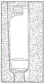
将流体输送到患者体内可以通过使用插入到患者体内的重力送料线(或管)来促进。通常,流体储存器(例如,IV袋)挂在杆上并且连接到流体管。流体管常常耦接到滴注腔以便捕获空气并且估计流体流。在流体管下方可以是用来调节流体的流动的人工致动阀。例如,通过计数在某一时间段内在滴注腔中形成的滴数,护理者能够计算流经滴注腔的流体的速率并且调节阀(如果需要)来实现期望的流量。Delivery of fluids into the patient may be facilitated by the use of a gravity feed line (or tube) inserted into the patient. Typically, a fluid reservoir (eg, an IV bag) hangs from a rod and connects to a fluid tube. Fluid tubes are often coupled to the drip chamber in order to trap air and estimate fluid flow. Below the fluid tube may be a manually actuated valve for regulating the flow of fluid. For example, by counting the number of drops formed in the drip chamber over a certain period of time, the caregiver can calculate the rate of fluid flowing through the drip chamber and adjust the valve (if needed) to achieve the desired flow rate.
某些治疗要求,流体输送系统严格地遵循由护理者设定的流量。通常,这样的应用使用注射泵,但是在所有情况或环境下可以不使用这样的泵。Certain treatments require that the fluid delivery system strictly follows the flow rate set by the caregiver. Typically, such applications use a syringe pump, but in all situations or circumstances such a pump may not be used.
发明内容SUMMARY OF THE INVENTION
简短且概括地讲,本公开涉及一种用于监测、调节或控制流体流的系统、方法和装置例如用于在诸如静脉注射治疗、透析、输血治疗、腹膜注射治疗、推注输送、肠内营养治疗、肠外营养治疗、血液灌流治疗、液体复苏治疗或胰岛素输送等的医学应用中使用。更具体地,本公开涉及一种用于监测与患者相关联的流体的流动的流体流量计、用于调节与患者相关联的流体的流动的阀、和/或耦接到阀(例如,以闭环、开环或反馈配置布置)的流体流量计以监测、调节和/或控制与患者相关联的流体的使用。Briefly and generally, the present disclosure relates to a system, method and apparatus for monitoring, regulating or controlling fluid flow, eg, for use in applications such as intravenous therapy, dialysis, blood transfusion therapy, peritoneal injection therapy, bolus delivery, enteral therapy Used in medical applications such as nutritional therapy, parenteral nutrition therapy, hemoperfusion therapy, fluid resuscitation therapy or insulin delivery. More particularly, the present disclosure relates to a fluid flow meter for monitoring the flow of fluid associated with a patient, a valve for regulating the flow of fluid associated with the patient, and/or coupled to a valve (eg, to closed-loop, open-loop, or feedback configurations) fluid flow meters to monitor, regulate, and/or control the use of fluids associated with a patient.
在本公开的一些实施例中,流量计包括一个或多个光学传感器以监测管内流体的流动,例如,使用图像传感器来监测附接到管的滴注腔内的液滴。流量计可以是独立的设备,可以结合泵或阀或泵和阀两者使用,和/或可以被用来为任意电子设备提供反馈。流量计可以例如通过监测客户端、远程通信器、智能电话、计算机等远程地被控制。流量计可以测量平均流量、瞬时流量、液滴体积、液滴增长率、或与流体流相关的其它参数。In some embodiments of the present disclosure, the flow meter includes one or more optical sensors to monitor the flow of fluid within the tube, eg, using an image sensor to monitor droplets within a drip chamber attached to the tube. The flow meter can be a stand-alone device, can be used in conjunction with a pump or valve or both, and/or can be used to provide feedback to any electronic device. The flow meter may be controlled remotely, eg, via a monitoring client, remote communicator, smartphone, computer, or the like. Flow meters can measure average flow, instantaneous flow, droplet volume, droplet growth rate, or other parameters related to fluid flow.
该流量计可以使用与流体流相关的流量或参数来:(1)将流量或参数显示在屏幕上,(2)(无线地或经电线)为诸如蠕动泵的注射泵提供反馈,所述反馈诸如为与流体流相关的流量或参数,(3)为诸如智能电话的监测客户端或远程监测客户端提供反馈,(4)当与流体流相关的流量或参数在预定范围之外时发出警告,(5)在与流体流相关的流量或参数在预定阈值以上的情况下发出警告,(6)在检测到自由流的情况下发出警告,(7)将警告传达至泵、监测客户端、或远程监测客户端,(8)当检测到自由流,发出警告,和/或与流体流相关的流量或参数在阈值以上或在预定范围之外时,指令阀停止流体流,和/或(9)广播与流体流相关的流量或参数。The flowmeter may use the flow or parameter related to fluid flow to: (1) display the flow or parameter on a screen, (2) provide feedback (wirelessly or via wire) to a syringe pump such as a peristaltic pump, the feedback Such as for fluid flow related flows or parameters, (3) to provide feedback to monitoring clients such as smartphones or remote monitoring clients, (4) to warn when fluid flow related flows or parameters are outside predetermined ranges , (5) issue a warning if a flow or parameter related to fluid flow is above a predetermined threshold, (6) issue a warning if free flow is detected, (7) communicate a warning to the pump, monitoring client, or a remote monitoring client, (8) instructing a valve to stop fluid flow when free flow is detected, a warning is issued, and/or a flow or parameter associated with fluid flow is above a threshold or outside a predetermined range, and/or ( 9) Broadcast flow or parameters related to fluid flow.
在本文中所描述的一些实施例中,阀调节与患者相关联的流体的流动。本文公开的阀可以是人工致动的或可以由致动器致动(或两者)。阀可以与或不与泵、与或不与流量计一起使用,和/或可以是独立的设备。阀可以例如通过监测客户端、远程通信器、智能电话、计算机等远程地被控制。阀可以沿着大体大于管的直径(例如,2倍以上、5倍以上、10倍以上等)的部分压缩管。In some embodiments described herein, the valve regulates the flow of fluid associated with the patient. The valves disclosed herein may be manually actuated or may be actuated by an actuator (or both). The valve may or may not be used with a pump, with or without a flow meter, and/or may be a stand-alone device. The valve may be controlled remotely, eg, via a monitoring client, remote communicator, smartphone, computer, or the like. The valve may compress the tube along a portion that is substantially larger than the diameter of the tube (eg, more than 2 times, more than 5 times, more than 10 times, etc.).
阀可以由压缩管的两个或更多个零件构成或可以由单个零件构成,在该零件移动或变形时,该单个零件压缩管。两个或更多个零件和/或单个零件可以使用注射成形、超声焊接、使用胶合或模制在一起的多个零件等来制造。两个或更多个零件中的每一个由可永久或临时地相互附接的一个或多个子部件构成。单个零件可以由例如使用超声焊接、胶合、锁定、或其它技术永久或临时地耦接在一起的一个或多个子部件来制造。这些零件可以是塑料、金属、合金、聚合物、或其它材料。The valve may consist of two or more parts that compress the tube or may consist of a single part that compresses the tube when the part moves or deforms. Two or more parts and/or a single part may be fabricated using injection molding, ultrasonic welding, using multiple parts glued or molded together, and the like. Each of the two or more parts is made up of one or more sub-components that are permanently or temporarily attachable to each other. A single part may be fabricated from one or more sub-components that are permanently or temporarily coupled together, eg, using ultrasonic welding, gluing, locking, or other techniques. These parts can be plastics, metals, alloys, polymers, or other materials.
在本公开的一些实施例中,流量计耦接到阀以调节流体流,例如到患者体内的流体流。耦接到阀的流量计可以代替泵(诸如蠕动注射泵)被使用,或可以是注射泵的替代物。流量计和阀组合可以例如通过监测客户端、远程通信器、智能电话、计算机等远程地被控制或可以远程地被监测。监测客户端可以控制流量计或阀,可以是在流量计和阀之间的中继器,可以监测流量计或阀的操作,可以将与流量计或阀相关的信息传达至服务器,和/或可以在系统中不被使用。In some embodiments of the present disclosure, a flow meter is coupled to a valve to regulate fluid flow, eg, into a patient. A flow meter coupled to the valve may be used in place of a pump, such as a peristaltic syringe pump, or may be an alternative to a syringe pump. The flow meter and valve combination can be controlled or can be monitored remotely, eg, via a monitoring client, remote communicator, smartphone, computer, or the like. The monitoring client can control the flowmeter or valve, can be a repeater between the flowmeter and the valve, can monitor the operation of the flowmeter or valve, can communicate information related to the flowmeter or valve to the server, and/or Can not be used in the system.
流量计可以监测流体的流动并且直接或间接地对阀或泵(例如,注射泵)做出调节。当流量计检测到自由流化(streaming)条件时,流量计可以报警,确定流量是否大于预定阈值或在预定范围之外,和/或检测任意异常行为。响应于警报或条件,流量计可以引起流量计停止流体流,指令阀停止流体流,指令安全阀停止流体流,告知监测客户端或远程通信器,广播检测到的条件,或执行预先定义例程或算法。Flow meters can monitor the flow of fluids and make adjustments to valves or pumps (eg, syringe pumps) directly or indirectly. When the flowmeter detects a free streaming condition, the flowmeter may alarm, determine if the flow rate is greater than a predetermined threshold or outside a predetermined range, and/or detect any abnormal behavior. In response to an alarm or condition, the flowmeter can cause the flowmeter to stop fluid flow, command a valve to stop fluid flow, command a safety valve to stop fluid flow, notify a monitoring client or remote communicator, broadcast a detected condition, or execute a predefined routine or algorithm.
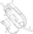
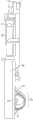
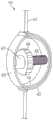
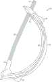
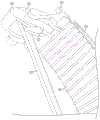
在本公开的某些实施例中,用于调节流体流的装置包括弯曲细长支撑构件和相对的支撑构件。弯曲细长支撑构件可弹性地变形并且具有第一端和第二端。相对的支撑构件被配置成将管抵靠弯曲细长支撑构件定位在第一端和第二端之间,使得由第一端和第二端朝向彼此的移动而引起的弯曲细长支撑构件的变形使管的内体积减小。相对的支撑构件可以是另一个弯曲细长支撑构件。In certain embodiments of the present disclosure, a device for regulating fluid flow includes a curved elongated support member and an opposing support member. The curved elongated support member is elastically deformable and has a first end and a second end. The opposing support member is configured to position the tube against the curved elongated support member between the first end and the second end such that the movement of the curved elongated support member caused by the movement of the first end and the second end toward each other The deformation reduces the internal volume of the tube. The opposing support member may be another curved elongated support member.
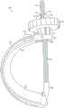
该装置可以包括致动器,该致动器耦接到弯曲细长支撑构件以通过致动器的致动使第一端和第二端朝向彼此移动而使弯曲细长支撑构件变形。在一些这样的实施例中,致动器可以是导螺杆,并且旋钮可以被耦接到导螺杆以驱动导螺杆。The apparatus may include an actuator coupled to the curved elongated support member to deform the curved elongated support member by actuation of the actuator to move the first and second ends toward each other. In some such embodiments, the actuator may be a lead screw, and the knob may be coupled to the lead screw to drive the lead screw.
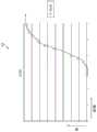
致动器、弯曲细长支撑构件、和相对的支撑构件可以被配置成通过致动器的致动根据Gompertz曲线来调节流体流。在一些实施例中,致动器可以进一步被配置成将第一端和第二端沿着Gompertz曲线的预定部分朝向彼此致动。例如,致动器可以仅沿着弯曲细长支撑构件和相对的支撑构件的可致动范围的一部分来致动致动器。The actuator, the curved elongated support member, and the opposing support member may be configured to regulate fluid flow according to the Gompertz curve through actuation of the actuator. In some embodiments, the actuator may be further configured to actuate the first end and the second end toward each other along a predetermined portion of the Gompertz curve. For example, the actuator may actuate the actuator along only a portion of the actuatable range of the curved elongated support member and the opposing support member.
致动器、弯曲细长支撑构件、和相对的支撑构件可以被配置成通过致动器的致动根据S型曲线来调节流体流。致动器可以进一步被配置成将第一端和第二端沿着S型曲线的预定部分朝向彼此致动。The actuator, the curved elongated support member, and the opposing support member may be configured to regulate fluid flow according to the S-curve upon actuation of the actuator. The actuator may be further configured to actuate the first end and the second end toward each other along a predetermined portion of the S-curve.
弯曲细长支撑构件可以是半刚性的和/或可以基本上由可拉伸材料构成。弯曲细长支撑构件可以是弓形、细长支撑构件、和/或可以是C形。The curved elongated support member may be semi-rigid and/or may consist essentially of a stretchable material. The curved elongated support members may be arcuate, elongated support members, and/or may be C-shaped.
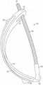
该装置可以进一步包括细长连接构件,该细长连接构件操作耦接到弯曲细长支撑构件的第一端和第二端。The device may further include an elongated connecting member operatively coupled to the first and second ends of the curved elongated support member.
在本公开的某些实施例中,该装置可以包括致动器,该致动器耦接到细长连接构件和弯曲细长支撑构件以施加向外扩张力以因此使弯曲细长支撑构件的第一端和第二端朝向彼此变形。In certain embodiments of the present disclosure, the device may include an actuator coupled to the elongated connecting member and the curved elongated support member to apply an outward expansion force to thereby cause the bending of the elongated support member The first and second ends are deformed toward each other.
在本公开的某些实施例中,弯曲细长支撑构件被布置成沿着其大部分大约平行于另一个弯曲细长支撑构件。例如,弯曲细长支撑构件限定长度,并且另一个弯曲细长支撑构件限定长度,并且另一个弯曲细长支撑构件的长度被布置成与弯曲细长支撑构件的长度近似平行。In certain embodiments of the present disclosure, the curved elongated support member is arranged approximately parallel to the other curved elongated support member along a substantial portion thereof. For example, a curved elongated support member defines a length, and another curved elongated support member defines a length, and the length of the other curved elongated support member is arranged approximately parallel to the length of the curved elongated support member.
在本公开的某些实施例中,该装置包括致动器,该致动器在第一端和第二端处操作耦接到弯曲细长支撑构件,并且在第一端和第二端处联接到另一个弯曲细长支撑构件。致动器的致动引起弯曲细长支撑构件的第一端和第二端彼此接近并且还引起另一个弯曲细长支撑构件的第一端和第二端彼此接近以因此引起在弯曲细长支撑构件和另一个弯曲细长支撑构件之间的距离的缩短以由此压缩管。In certain embodiments of the present disclosure, the device includes an actuator operatively coupled to the curved elongated support member at first and second ends, and at the first and second ends is coupled to another curved elongated support member. Actuation of the actuator causes the first and second ends of the curved elongated support member to approach each other and also causes the first and second ends of the other curved elongated support member to approach each other to thereby cause the curved elongated support The shortening of the distance between the member and the other curved elongated support member thereby compresses the tube.
在本公开的某些实施例中,弯曲细长支撑构件限定长度,并且相对的支撑构件被布置成沿着该长度的一部分与之正交。In certain embodiments of the present disclosure, the curved elongated support members define a length, and the opposing support members are arranged orthogonal thereto along a portion of the length.
在本公开的某些实施例中,弯曲细长支撑构件包括布置于其上以接合管的多个脊部。In certain embodiments of the present disclosure, the curved elongated support member includes a plurality of ridges disposed thereon to engage the tube.
在本公开的某些实施例中,相对的支撑构件包括布置于其上以接合管的多个脊部。In certain embodiments of the present disclosure, the opposing support members include a plurality of ridges disposed thereon to engage the tube.
在本公开的某些实施例中,弯曲细长支撑构件包括从其长度延伸的凸缘,该凸缘被配置成保持管。相对的支撑构件可以包括从其长度延伸的另一个凸缘,该另一个凸缘被配置成保持管,使得凸缘和另一个凸缘约彼此平行并且大约平行于当管被布置在凸缘和另一个凸缘之间时由管限定的中心轴线。In certain embodiments of the present disclosure, the curved elongated support member includes a flange extending from its length configured to retain the tube. The opposing support member may include another flange extending from its length configured to retain the tube such that the flange and the other flange are approximately parallel to each other and approximately parallel to when the tube is disposed between the flange and the tube. The central axis defined by the tube when between the other flanges.
在本公开的某些实施例中,用于调节流体流的装置包括第一细长支撑构件、第二细长支撑构件、和致动器。第一细长支撑构件限定长度,并且第二细长支撑构件也限定其自身的长度,使得第二细长支撑构件的长度被布置成与第一细长支撑构件的长度呈间隔开关系(spaced relation)以与第一细长支撑构件相配合以压缩管。致动器与第一和第二细长支撑构件中的至少一个机械接合,以将第一和第二细长支撑构件朝向彼此致动,以因此压缩布置在第一和第二细长支撑构件之间的管以调节管内的流体的流动,使得致动器的致动致动第一和第二细长支撑构件以根据近似S型曲线来调节管内的流体流。In certain embodiments of the present disclosure, an apparatus for regulating fluid flow includes a first elongated support member, a second elongated support member, and an actuator. The first elongated support member defines a length and the second elongated support member also defines its own length such that the length of the second elongated support member is arranged in spaced relation to the length of the first elongated support member relation) to cooperate with the first elongated support member to compress the tube. The actuator is in mechanical engagement with at least one of the first and second elongated support members to actuate the first and second elongated support members towards each other to thereby compress the arrangement between the first and second elongated support members A tube between to regulate the flow of fluid within the tube such that actuation of the actuator actuates the first and second elongated support members to regulate the flow of fluid within the tube according to an approximate S-curve.
第二细长支撑构件的长度可以被布置成大约平行于第一细长支撑构件的长度。第一和第二细长支撑构件可以被配置成彼此相配合以沿着管的至少大体大于管的直径的长度压缩管。致动器可以被配置成致动第一和第二细长支撑构件以压缩管以沿着S型曲线的预定部分来调节管内的流体流。The length of the second elongated support member may be arranged approximately parallel to the length of the first elongated support member. The first and second elongated support members may be configured to cooperate with each other to compress the tube along a length of the tube that is at least substantially larger than the diameter of the tube. The actuator may be configured to actuate the first and second elongated support members to compress the tube to regulate fluid flow within the tube along a predetermined portion of the S-curve.
在本公开的某些实施例中,用于调节流体流的装置包括第一和第二细长支撑构件。第一细长支撑构件限定长度,并且第二细长支撑构件限定长度。第二细长支撑构件的长度被布置成与第一细长支撑构件的长度呈间隔开关系以与第一细长支撑构件相配合以压缩管。致动器与第一和第二细长支撑构件中的至少一个机械接合,以将第一和第二细长支撑构件朝向彼此致动,以因此压缩布置在第一和第二细长支撑构件之间的管以调节管内的流体的流动,使得致动器的致动致动第一和第二细长支撑构件以根据近似Gompertz曲线来调节管内的流体流。In certain embodiments of the present disclosure, an apparatus for regulating fluid flow includes first and second elongated support members. The first elongated support member defines a length, and the second elongated support member defines a length. The length of the second elongated support member is arranged in spaced relation to the length of the first elongated support member to cooperate with the first elongated support member to compress the tube. The actuator is in mechanical engagement with at least one of the first and second elongated support members to actuate the first and second elongated support members towards each other to thereby compress the arrangement between the first and second elongated support members A tube between to regulate the flow of fluid within the tube such that actuation of the actuator actuates the first and second elongated support members to regulate the flow of fluid within the tube according to an approximate Gompertz curve.
第二细长支撑构件的长度可以被布置成大约平行于第一细长支撑构件的长度。第一和第二细长支撑构件可以被配置成彼此相配合以沿着管的至少大体大于管的直径的长度压缩管。The length of the second elongated support member may be arranged approximately parallel to the length of the first elongated support member. The first and second elongated support members may be configured to cooperate with each other to compress the tube along a length of the tube that is at least substantially larger than the diameter of the tube.
致动器可以被配置成致动第一和第二细长支撑构件以压缩管以根据Gompertz曲线的预定部分来调节管内的流体流。The actuator may be configured to actuate the first and second elongated support members to compress the tube to regulate fluid flow within the tube according to a predetermined portion of the Gompertz curve.
在本公开的某些实施例中,用于调节流体流的装置包括第一和第二细长支撑构件。第一细长支撑构件限定长度,并且第二细长支撑构件限定长度,使得第二细长支撑构件的长度被布置成与第一细长支撑构件的长度呈间隔开关系以与第一细长支撑构件相配合以压缩管。致动器与第一和第二细长支撑构件中的至少一个机械接合,以将第一和第二细长支撑构件朝向彼此致动,以因此压缩布置在第一和第二细长支撑构件之间的管以调节管内的流体的流动,使得致动器的致动致动第一和第二细长支撑构件以根据近似广义logistic函数来调节管内的流体流。In certain embodiments of the present disclosure, an apparatus for regulating fluid flow includes first and second elongated support members. The first elongated support member defines a length and the second elongated support member defines a length such that the length of the second elongated support member is arranged in spaced relation to the length of the first elongated support member to be in a spaced relationship with the first elongated support member The support members cooperate to compress the tube. The actuator is in mechanical engagement with at least one of the first and second elongated support members to actuate the first and second elongated support members towards each other to thereby compress the arrangement between the first and second elongated support members a tube between to regulate the flow of fluid within the tube such that actuation of the actuator actuates the first and second elongated support members to regulate the flow of fluid within the tube according to an approximated generalized logistic function.
第二细长支撑构件的长度可以被布置成大约平行于第一细长支撑构件的长度。第一和第二细长支撑构件可以被配置成彼此相配合以沿着管的至少大体大于管的直径的长度压缩管。致动器可以进一步被配置成致动第一和第二细长支撑构件以压缩管以根据广义logistic函数的预定部分来调节管内的流体流。The length of the second elongated support member may be arranged approximately parallel to the length of the first elongated support member. The first and second elongated support members may be configured to cooperate with each other to compress the tube along a length of the tube that is at least substantially larger than the diameter of the tube. The actuator may be further configured to actuate the first and second elongated support members to compress the tube to regulate fluid flow within the tube according to a predetermined portion of the generalized logistic function.
在本公开的某些实施例中,用于调节流体流的装置包括第一和第二支撑构件以及致动器。第一支撑构件形成弧、多个弧、曲线、多个曲线、弓形、多个弓形、S形、C形、凸形、多个凸形、凹形和多个凹形中的至少一个。第二支撑构件被布置成与第一支撑构件成间隔开关系以与第一支撑构件相配合以沿着管的至少大体大于管的直径的长度压缩管。致动器与第一和第二支撑构件中的至少一个机械接合,以将第一和第二支撑构件朝向彼此致动,以因此压缩布置在第一和第二支撑构件之间的管以调节管内的流体的流动,使得致动器的致动致动第一和第二细长支撑构件以根据近似非线性函数来调节管内的流体流。In certain embodiments of the present disclosure, an apparatus for regulating fluid flow includes first and second support members and an actuator. The first support member forms at least one of an arc, arcs, curves, curves, arcs, arcs, S, C, convex, convex, concave, and concave. The second support member is arranged in spaced relation to the first support member to cooperate with the first support member to compress the tube along a length of the tube at least substantially larger than the diameter of the tube. An actuator is mechanically engaged with at least one of the first and second support members to actuate the first and second support members towards each other to thereby compress a tube disposed between the first and second support members for adjustment The flow of fluid within the tube such that actuation of the actuator actuates the first and second elongated support members to regulate fluid flow within the tube according to an approximately nonlinear function.
近似非线性函数可以是近似广义logistic函数、近似S型曲线、和/或近似Gompertz曲线。致动器可以被配置成致动以因此根据近似非线性函数的预定部分来调节管内的流体流。The approximated nonlinear function may be an approximated generalized logistic function, an approximated S-curve, and/or an approximated Gompertz curve. The actuator may be configured to actuate to thereby regulate fluid flow within the tube according to a predetermined portion of the approximate nonlinear function.
在本公开的某些实施例中,第一支撑构件形成弧,具有基本上由弧构成的形状,形成多个弧,具有基本上由多个弧构成的形状,形成曲线,具有基本上由曲线构成的形状,形成多个曲线,具有基本上由多个曲线构成的形状,形成弓形,具有基本上由弓形构成的形状,形成多个弓形,具有基本上由多个弓形构成的形状,形成S形,具有基本上由S形构成的形状,形成C形,具有基本上由C形构成的形状,形成凸形,具有基本上由凸形构成的形状,形成多个凸形,具有基本上由多个凸形构成的形状,形成凹形,具有基本上由凹形构成的形状,形成多个凹形,和/或具有基本上由多个凹形构成的形状。In certain embodiments of the present disclosure, the first support member forms an arc, has a shape consisting essentially of an arc, forms a plurality of arcs, has a shape that consists essentially of a plurality of arcs, forms a curve, has a shape consisting essentially of a curve Constructed shape, forming a plurality of curves, having a shape consisting essentially of a plurality of curves, forming an arc, having a shape consisting essentially of an arc, forming a plurality of arcs, having a shape consisting essentially of a plurality of arcs, forming S shape, having a shape consisting essentially of an S shape, forming a C shape, having a shape consisting essentially of a C shape, forming a convex shape, having a shape consisting essentially of a convex shape, forming a plurality of convex shapes, having a shape consisting essentially of a convex shape A shape consisting of a plurality of convex shapes, forming a concave shape, having a shape consisting essentially of a concave shape, forming a plurality of concave shapes, and/or having a shape consisting essentially of a plurality of concave shapes.
第二支撑构件的长度可以被布置成大约平行于第一支撑构件的长度。第一和第二支撑构件可以被配置成彼此相配合以沿着管的至少大体大于管的直径的长度压缩管。The length of the second support member may be arranged approximately parallel to the length of the first support member. The first and second support members may be configured to cooperate with each other to compress the tube along a length of the tube that is at least substantially larger than the diameter of the tube.
在本公开的某些实施例中,用于调节流体流的装置包括弯曲细长支撑构件和相对的支撑构件。弯曲细长支撑构件可弹性地变形并且具有第一端和第二端。相对的支撑构件被配置成与弯曲细长支撑构件限定导管,使得导管被限定在弯曲细长支撑构件和相对的构件之间。由第一端和第二端朝向彼此的移动而引起的弯曲细长支撑构件的变形减小导管的内体积。在一些实施例中,导管可以被配置成接纳管。在其它的实施例中,导管被流体地密封,并且装置进一步包括与导管流体连通的第一和第二端口,使得每个端口适于耦接到管。In certain embodiments of the present disclosure, a device for regulating fluid flow includes a curved elongated support member and an opposing support member. The curved elongated support member is elastically deformable and has a first end and a second end. The opposing support member is configured to define a conduit with the curved elongated support member such that the conduit is defined between the curved elongated support member and the opposing member. Deformation of the curved elongated support member caused by movement of the first and second ends towards each other reduces the inner volume of the catheter. In some embodiments, the conduit may be configured to receive a tube. In other embodiments, the conduit is fluidly sealed, and the device further includes first and second ports in fluid communication with the conduit, such that each port is adapted to couple to a tube.
在本公开的某些实施例中,用于调节流体流的系统包括挠性管和反置波登管阀。挠性流体管具有流体路径并且被配置成用于使流体通过它。反置波登管阀耦接到挠性流体管以调节流经挠性流体管的流体路径的流体。致动器可以耦接到反置波登管阀以致动反置波登管阀以调节流经挠性流体管的流体路径的流体。反置波登管阀以与波登管相反的方式工作,流体路径的变形引起流体流改变而非流体流引起流体路径的变形。In certain embodiments of the present disclosure, a system for regulating fluid flow includes a flexible tube and an inverted Bourdon tube valve. The flexible fluid tube has a fluid path and is configured for passing fluid therethrough. An inverted Bourdon tube valve is coupled to the flexible fluid tube to regulate fluid flow through the fluid path of the flexible fluid tube. An actuator may be coupled to the inverted Bourdon tube valve to actuate the inverted Bourdon tube valve to regulate fluid flow through the fluid path of the flexible fluid tube. Inverted Bourdon tube valves work in the opposite way to a Bourdon tube, with the deformation of the fluid path causing the fluid flow to change rather than the fluid flow causing the deformation of the fluid path.
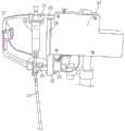
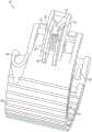
在本公开的某些实施例中,用于调节流体流的系统包括流体管、阀和致动器。流体管限定被配置成用于让流体通过它的流体路径。阀操作耦接到流体管并且包括第一和第二挠性构件。第二挠性构件操作耦接到第一挠性构件。流体管被布置在第一和第二挠性构件之间,并且第一和第二挠性构件被配置成挠曲以因此调节通过流体管的流体的流动。致动器耦接到第一挠性构件的至少第一端和第一挠性构件的第二端。致动器可以是导螺杆并且可能存在耦接到导螺杆以使导螺杆旋转的电动机。In certain embodiments of the present disclosure, a system for regulating fluid flow includes a fluid tube, a valve, and an actuator. The fluid tube defines a fluid path configured for passing fluid therethrough. A valve is operatively coupled to the fluid tube and includes first and second flexible members. The second flexible member is operatively coupled to the first flexible member. A fluid tube is disposed between the first and second flexible members, and the first and second flexible members are configured to flex to thereby regulate the flow of fluid through the fluid tube. An actuator is coupled to at least the first end of the first flexible member and the second end of the first flexible member. The actuator may be a lead screw and there may be a motor coupled to the lead screw to rotate the lead screw.
在本公开的某些实施例中,系统可以包括旋钮,该旋钮耦接到导螺杆,使得该旋钮被配置成使导螺杆旋转。旋钮可以由电机驱动的致动器接合。In certain embodiments of the present disclosure, the system may include a knob coupled to the lead screw such that the knob is configured to rotate the lead screw. The knob may be engaged by a motor-driven actuator.
在本公开的某些实施例中,致动器耦接到第一挠性构件的第一端和第一挠性构件的第二端,并且致动器被配置成使第一端和第二端朝向彼此挠曲和使第一端和第二端离开彼此挠曲中的至少一者。致动器可以使第一端和第二端离开彼此挠曲,和/或致动器使第一和第二挠性构件挠曲使得第一端和第二端彼此接近。第一和第二挠性构件可以是大致矩形。当致动器停止力的施加时,第一构件和/或第二构件可以被张紧使流体流至少大体停止。In certain embodiments of the present disclosure, the actuator is coupled to the first end of the first flexible member and the second end of the first flexible member, and the actuator is configured to cause the first end and the second end At least one of flexing the ends toward each other and flexing the first and second ends away from each other. The actuator may flex the first and second ends away from each other, and/or the actuator may flex the first and second flexible members such that the first and second ends approach each other. The first and second flexible members may be generally rectangular. When the actuator stops application of the force, the first member and/or the second member may be tensioned to at least substantially stop fluid flow.
系统可以包括耦接到滴注腔(耦接到流体管)的流量计,使得流量计估计通过滴注腔的流体流并且因此还估计通过流体管的流体流。流量计可以是基于图像传感器的流量计。The system may include a flow meter coupled to the drip chamber (coupled to the fluid tube) such that the flow meter estimates fluid flow through the drip chamber and thus also fluid flow through the fluid tube. The flow meter may be an image sensor based flow meter.
流量计可以操作耦接到电机以致动阀,并且系统可以包括控制部件以控制电机以致动阀以实现如由流量计估计的期望的流量。The flow meter may be operatively coupled to the motor to actuate the valve, and the system may include control components to control the motor to actuate the valve to achieve a desired flow rate as estimated by the flow meter.
在本公开的某些实施例中,用于调节流体流的装置包括第一和第二C形构件。第一C形构件限定内表面和外表面,并且第二C形构件限定内表面和外表面。第一C形构件的外表面和第二C形构件的内表面中的至少一个被配置成接纳管。第二C形构件的内表面被布置成与第一C形构件的外表面呈间隔开关系。在一些特定实施例中,第二C形构件的内表面的大量区域可以紧靠第一C形构件的外表面。In certain embodiments of the present disclosure, a device for regulating fluid flow includes first and second C-shaped members. The first C-shaped member defines inner and outer surfaces, and the second C-shaped member defines inner and outer surfaces. At least one of the outer surface of the first C-shaped member and the inner surface of the second C-shaped member is configured to receive a tube. The inner surface of the second C-shaped member is arranged in spaced relation to the outer surface of the first C-shaped member. In some particular embodiments, a substantial area of the inner surface of the second C-shaped member may abut against the outer surface of the first C-shaped member.
在本公开的某些实施例中,第二C形构件是挠性的,并且第一C形构件是半刚性的,是刚性的,和/或是弹性体。In certain embodiments of the present disclosure, the second C-shaped member is flexible and the first C-shaped member is semi-rigid, rigid, and/or elastomeric.
挠性构件可以由从由塑、聚合物、单体、聚丙烯、热塑性聚合物、陶瓷、聚氯乙烯、和聚乙烯组成的组选择的材料形成。The flexible member may be formed from a material selected from the group consisting of plastic, polymer, monomer, polypropylene, thermoplastic polymer, ceramic, polyvinyl chloride, and polyethylene.
在本公开的某些实施例中,用于调节流体流的装置包括第一和第二挠性片。第二挠性片操作耦接到第一挠性片。第一和第二挠性片被配置成接纳在它们之间的流体管,并且第一和第二挠性片还被配置成挠曲以因此调节通过流体管的流体的流动。In certain embodiments of the present disclosure, a device for regulating fluid flow includes first and second flexible sheets. The second flexible sheet is operatively coupled to the first flexible sheet. The first and second flexible sheets are configured to receive the fluid tube therebetween, and the first and second flexible sheets are also configured to flex to thereby regulate the flow of fluid through the fluid tube.
该装置可以包括致动器,该致动器耦接到第一挠性片的第一端和第一挠性片的第二端。致动器可以被配置成使第一端和第二端朝向彼此挠曲和使第一端和第二端离开彼此挠曲中的至少一者。The device may include an actuator coupled to the first end of the first flexible sheet and the second end of the first flexible sheet. The actuator may be configured to at least one of deflect the first end and the second end toward each other and flex the first end and the second end away from each other.
该装置可以包括导螺杆和旋钮,该导螺杆耦接到第一挠性片的第一端和第一挠性片的第二端,该旋钮耦接到导螺杆,使得旋钮的旋转使导螺杆旋转。旋钮可以被配置成用于与电机驱动的致动器接合,因而电机驱动的致动器致动旋钮。The device may include a lead screw coupled to the first end of the first flexible sheet and the second end of the first flexible sheet, and a knob coupled to the lead screw such that rotation of the knob causes the lead screw rotate. The knob may be configured for engagement with a motor-driven actuator such that the motor-driven actuator actuates the knob.
在本公开的某些实施例中,用于调节流体流的装置包括第一和第二曲线形构件。第一曲线形构件限定内表面和外表面,并且第二曲线形构件也限定内表面和外表面。第二曲线形构件的内表面被布置成与第一曲线形构件的外表面呈间隔开关系。In certain embodiments of the present disclosure, a device for regulating fluid flow includes first and second curvilinear members. The first curvilinear member defines inner and outer surfaces, and the second curvilinear member also defines inner and outer surfaces. The inner surface of the second curvilinear member is arranged in spaced relation to the outer surface of the first curvilinear member.
第一和第二曲线形构件中的至少一个可以被配置成将流体管定位在它们之间。第一曲线形构件可以是半刚性和刚性中的至少一者。第二曲线形构件可以是挠性的。第二曲线形构件可以包括弹性体。第一和第二曲线形构件可以是挠性的。At least one of the first and second curvilinear members may be configured to position the fluid tube therebetween. The first curvilinear member may be at least one of semi-rigid and rigid. The second curvilinear member may be flexible. The second curvilinear member may comprise an elastomer. The first and second curvilinear members may be flexible.
该装置可以包括连接构件,该连接构件操作耦接第一曲线形构件的第一端和第二曲线形构件的第一端中的至少一个,使得该连接构件还操作耦接到第一曲线形构件的第二端和第二曲线形构件的第二端中的至少一个。连接构件可以是挠性的,可以是刚性的,和/或可以是半刚性的。The device may include a connecting member operatively coupled to at least one of the first end of the first curvilinear member and the first end of the second curvilinear member such that the connecting member is also operatively coupled to the first curvilinear member At least one of the second end of the member and the second end of the second curvilinear member. The connecting member may be flexible, may be rigid, and/or may be semi-rigid.
该装置可以包括致动器,该致动器定位在连接构件和第二曲线形构件之间以当被致动时在连接构件和第二曲线形构件之间施加力。致动器可以是导螺杆。The device may include an actuator positioned between the connecting member and the second curvilinear member to apply a force between the connecting member and the second curvilinear member when actuated. The actuator may be a lead screw.
在本公开的某些实施例中,用于调节流体流的装置包括第一和第二曲线形构件。第一曲线形构件限定内表面和外表面。第一曲线形构件在该第一曲线形构件的两端处具有第一接纳构件和第二接纳构件。第二曲线形构件限定内表面和外表面。第二曲线形构件在该第二曲线形构件的两端处具有第一紧固件和第二紧固件。第一和第二紧固件中的至少一个可以是钩。第一曲线形构件的第一接纳构件被配置成接合第二曲线形构件的第一紧固件,并且第一曲线形构件的第二接纳构件被配置成接合第二曲线形构件的第二紧固件。In certain embodiments of the present disclosure, a device for regulating fluid flow includes first and second curvilinear members. The first curvilinear member defines an inner surface and an outer surface. The first curved member has a first receiving member and a second receiving member at both ends of the first curved member. The second curvilinear member defines an inner surface and an outer surface. The second curvilinear member has first and second fasteners at both ends of the second curvilinear member. At least one of the first and second fasteners may be a hook. The first receiving member of the first curved member is configured to engage the first fastener of the second curved member, and the second receiving member of the first curved member is configured to engage the second fastener of the second curved member firmware.
接纳构件中的至少一个可以被配置成用于耦接到钩的圆柱形构件,诸如筒状螺母。At least one of the receiving members may be configured as a cylindrical member, such as a barrel nut, for coupling to the hook.
接纳构件中的至少一个可以操作耦接到致动器。接纳构件中的一个或多个可以操作耦接到电动机。At least one of the receiving members is operably coupled to the actuator. One or more of the receiving members may be operatively coupled to the motor.
在本公开的某些实施例中,该装置进一步包括耦接到第一接纳构件的电动机,使得:(1)电动机使耦接到在其外表面上具有螺纹的轴的转子旋转;(2)第二接纳构件限定被配置成接纳轴的螺纹孔;以及(3)当电动机使转子旋转以因此使轴旋转时,螺纹孔和轴配合在一起以实现增加或减小第一和第二接纳构件之间的距离中的至少一者。In certain embodiments of the present disclosure, the apparatus further includes a motor coupled to the first receiving member such that: (1) the motor rotates a rotor coupled to a shaft having threads on an outer surface thereof; (2) The second receiving member defines a threaded hole configured to receive the shaft; and (3) when the motor rotates the rotor to thereby rotate the shaft, the threaded hole and the shaft mate together to effect increasing or decreasing the first and second receiving members at least one of the distances between.
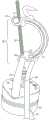
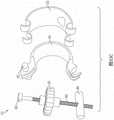
在本公开的某些实施例中,用于调节流体流的装置包括第一和第二弯曲细长支撑构件。该第一弯曲细长支撑构件可弹性地变形并且具有第一端和第二端。该第二弯曲细长支撑构件可弹性地变形并且具有第一端和第二端。该第二弯曲细长支撑构件被配置成将管抵靠第一弯曲细长支撑构件定位,使得由第一弯曲细长支撑构件的第一端和第二端朝向彼此的移动而引起的第一和第二弯曲细长支撑构件的变形使管的内体积减小。In certain embodiments of the present disclosure, a device for regulating fluid flow includes first and second curved elongated support members. The first curved elongated support member is elastically deformable and has a first end and a second end. The second curved elongated support member is elastically deformable and has a first end and a second end. The second curved elongated support member is configured to position the tube against the first curved elongated support member such that the first and second ends of the first curved elongated support member are caused by movement towards each other and the deformation of the second curved elongated support member reduces the inner volume of the tube.
第一连接器耦接到第一弯曲细长支撑构件的第一端并且还耦接到第二弯曲细长支撑构件的第一端。第二连接器耦接到第一弯曲细长支撑构件的第二端并且还耦接到第二弯曲细长支撑构件的第二端。第二连接器限定孔。连接构件具有耦接到第一连接器的一端和被配置成用于插入到第二连接器的孔中的另一端。连接构件至少沿着其部分限定螺纹杆。旋钮具有棘齿,被配置成当从连接构件的另一端朝连接器构件的一端移动时棘合到连接器构件。旋钮进一步被配置成接合连接构件的螺纹杆。旋钮可以包括被配置成接合连接构件的螺纹杆的多个指形件。旋钮限定外周并且包括在旋钮的外周的中心处限定的孔。孔被配置成接纳螺纹杆。多个指形件每一个为弧以在该多个指形件中的每一个的相应的端部处接合螺纹杆。The first connector is coupled to the first end of the first curved elongated support member and is also coupled to the first end of the second curved elongated support member. The second connector is coupled to the second end of the first curved elongated support member and is also coupled to the second end of the second curved elongated support member. The second connector defines a hole. The connecting member has one end coupled to the first connector and the other end configured for insertion into the hole of the second connector. The connecting member defines a threaded rod along at least a portion thereof. The knob has ratchet teeth configured to ratchet to the connector member when moved from the other end of the connecting member toward the one end of the connector member. The knob is further configured to engage the threaded rod of the connecting member. The knob may include a plurality of fingers configured to engage the threaded rod of the connecting member. The knob defines an outer periphery and includes a hole defined at the center of the outer periphery of the knob. The hole is configured to receive a threaded rod. Each of the plurality of fingers is arcuate to engage a threaded rod at a respective end of each of the plurality of fingers.
第一弯曲细长支撑构件限定与第一弯曲细长支撑构件的第一端相邻的第一孔。该孔被配置成保持流体管。The first curved elongated support member defines a first aperture adjacent the first end of the first curved elongated support member. The hole is configured to hold a fluid tube.
第一弯曲细长支撑构件可以限定与第一弯曲细长支撑构件的第一端相邻的第一凹槽,使得凹槽被配置成接纳流体管。该凹槽可以包括被配置成接纳流体管的颈部和被配置成保持流体管的圆形区域。The first curved elongated support member may define a first groove adjacent the first end of the first curved elongated support member such that the groove is configured to receive the fluid tube. The groove may include a neck configured to receive the fluid tube and a circular area configured to retain the fluid tube.
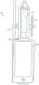
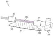
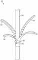
在本公开的某些实施例中,用于调节流体流的装置包括基座、多个指形件和环。基座限定被配置成接纳流体管的孔。多个指形件各自具有耦接到基座的一端。环被配置成从基座开始并且沿着多个指形件滑动。环从基座离开并且朝指形件的移动抵靠管压缩指形件。环被配置成抵靠多个指形件摩擦地锁定。每个指形件包括耦接到基座的细长端和相对于基座耦接到相对端的弯曲端。In certain embodiments of the present disclosure, a device for regulating fluid flow includes a base, a plurality of fingers, and a ring. The base defines an aperture configured to receive a fluid tube. The plurality of fingers each have one end coupled to the base. The ring is configured to start from the base and slide along the plurality of fingers. Movement of the ring away from the base and toward the fingers compresses the fingers against the tube. The ring is configured to frictionally lock against the plurality of fingers. Each finger includes an elongated end coupled to the base and a curved end coupled to an opposite end relative to the base.
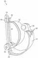
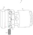
在本公开的某些实施例中,用于调节流体流的装置包括圆锥形构件、补充构件、和致动器。圆锥形构件具有用于缠绕其围绕的管的表面。补充构件被配置成接合圆锥形构件以便压缩管。致动器被配置成抵靠补充构件压缩圆锥形构件以因此压缩管。In certain embodiments of the present disclosure, a device for regulating fluid flow includes a conical member, a complementary member, and an actuator. The conical member has a surface for wrapping the tube around it. The complementary member is configured to engage the conical member to compress the tube. The actuator is configured to compress the conical member against the complementary member to thereby compress the tube.
在本公开的某些实施例中,静脉给药装置包括:挠性管,该挠性管用于引导其内的流体流;在挠性管的第一端处的第一端口;在挠性管的第二端处的第二端口;弯曲细长支撑构件,该弯曲细长支撑构件可弹性地变形并且具有第一端和第二端;和相对的支撑构件,该相对的支撑构件被配置成将挠性管抵靠弯曲细长支撑构件定位在第一端和第二端之间,使得由第一端和第二端朝向彼此的移动而引起的弯曲细长支撑构件的变形使管的内体积减小。In certain embodiments of the present disclosure, an intravenous drug delivery device includes: a flexible tube for directing fluid flow therein; a first port at a first end of the flexible tube; a flexible tube at a first end of the flexible tube a second port at a second end of the Positioning the flexible tube against the curved elongated support member between the first end and the second end such that deformation of the curved elongated support member caused by movement of the first and second ends toward each other causes the inner portion of the tube Volume is reduced.
静脉给药装置可以进一步包括:耦接到挠性管的滴注腔;另一个端口,被配置成接纳将流体注射到挠性管内的流体流中的注射器,和/或耦接到挠性管的滑动封堵器,被配置成接合挠性管以封堵其内的流体流。The IV set may further comprise: an instillation lumen coupled to the flexible tubing; another port configured to receive a syringe that injects fluid into the fluid flow within the flexible tubing, and/or coupled to the flexible tubing The sliding occluder is configured to engage the flexible tubing to occlude fluid flow therein.
弯曲细长支撑构件的第一端可以限定用以接纳挠性管的第一孔,并且弯曲细长支撑构件的第二端可以限定用以接纳挠性管的第二孔。The first end of the curved elongated support member may define a first aperture for receiving the flexible tube, and the second end of the curved elongated support member may define a second aperture for receiving the flexible tube.
在本公开的某些实施例中,流量计包括耦接器、支撑构件、第一和第二图像传感器和至少一个处理器。耦接器适于耦接到滴注腔。支撑构件操作耦接到耦接器。第一图像传感器具有第一视场并且操作耦接到支撑构件。第一图像传感器定位成在第一视场内观察滴注腔。第二图像传感器具有第二视场并且操作耦接到支撑构件。第二图像传感器定位成在第二视场内观察滴注腔。In certain embodiments of the present disclosure, a flow meter includes a coupler, a support member, first and second image sensors, and at least one processor. The coupler is adapted to be coupled to the drip chamber. The support member is operatively coupled to the coupler. The first image sensor has a first field of view and is operatively coupled to the support member. The first image sensor is positioned to view the drip chamber within the first field of view. The second image sensor has a second field of view and is operatively coupled to the support member. The second image sensor is positioned to view the drip chamber within the second field of view.
至少一个处理器操作耦接到第一和第二图像传感器。至少一个处理器从第一图像传感器接收第一图像数据并且从第二图像传感器接收第二图像数据,并且至少一个处理器使用第一和第二图像数据来估计滴注腔内的液体的至少一个参数。At least one processor is operatively coupled to the first and second image sensors. At least one processor receives first image data from the first image sensor and second image data from the second image sensor, and the at least one processor uses the first and second image data to estimate at least one of the liquid within the drip chamber parameter.
该至少一个参数可以为液体的形成类型、液体的体积、和液体的形状中的一个。至少一个处理器可以使用第一和第二组的图像数据中的至少一个来确定自由流条件的存在。The at least one parameter may be one of the type of formation of the liquid, the volume of the liquid, and the shape of the liquid. At least one processor may use at least one of the first and second sets of image data to determine the existence of a free-flow condition.
流量计可以进一步包括背景图案,该背景图案定位在第一图像传感器的视场内,使得滴注腔在第一图像传感器和背景图案之间。The flow meter may further include a background pattern positioned within the field of view of the first image sensor such that the drip chamber is between the first image sensor and the background pattern.
通过分析如由第一图像传感器观察的由在第一视场内的液体引起的背景图案的变形,流量计的至少一个处理器可以使用第一组图像数据来估计至少一个参数。背景图案可以是线阵列,当从使用第一组图像数据的第一视场内的第一图像传感器观察时,该线阵列相对于滴注腔的开口具有至少一个角度。At least one processor of the flow meter can use the first set of image data to estimate at least one parameter by analyzing the deformation of the background pattern caused by the liquid within the first field of view as viewed by the first image sensor. The background pattern may be an array of lines having at least one angle relative to the opening of the drip chamber when viewed from the first image sensor within the first field of view using the first set of image data.
当在如在第一视场内从第一图像传感器观察的自由流条件下时,当液体引起线阵列因液体引起的变形而改变角度时,至少一个处理器可以确定自由流条件存在。The at least one processor may determine that a free flow condition exists when the liquid causes the line array to change angle due to liquid induced deformation under free flow conditions as viewed from the first image sensor within the first field of view.
至少一个处理器可以将第一和第二图像数据中的至少一个与背景图像相比较以估计至少一个参数。At least one processor may compare at least one of the first and second image data to a background image to estimate at least one parameter.
通过计算第一和第二图像数据中的至少一个与背景图像之间的差、第一和第二图像数据中的至少一个与背景图像的绝对差、和/或第一和第二图像数据中的至少一个与背景图像的平方绝对差,至少一个处理器可以将第一和第二图像数据中的至少一个与背景图像相比较。By calculating the difference between at least one of the first and second image data and the background image, the absolute difference between at least one of the first and second image data and the background image, and/or the difference between the first and second image data A squared absolute difference of at least one of the at least one processor and the background image, the at least one processor may compare at least one of the first and second image data to the background image.
流量计可以包括与至少一个处理器可操作通信的非暂态处理器可读存储器,使得存储器存储被配置成用于由至少一个处理器执行的可操作处理器可执行指令组。可操作处理器可执行指令组当由至少一个处理器执行时控制该至少一个处理器的操作。The flow meter may include a non-transitory processor-readable memory in operative communication with the at least one processor, such that the memory stores a set of operable processor-executable instructions configured for execution by the at least one processor. An operable set of processor-executable instructions, when executed by at least one processor, controls the operation of the at least one processor.
在本公开的某些实施例中,流量计包括耦接器、支撑构件、背景图案和至少一个处理器。耦接器适于耦接到滴注腔。支撑构件操作耦接到耦接器。图像传感器具有视场并且操作耦接到支撑构件。图像传感器定位成在视场内观察滴注腔。背景图案被定位在图像传感器的视场内。背景图案定位成使得滴注腔在背景图案和图像传感器之间。至少一个处理器操作耦接到图像传感器以从其接收图像数据。至少一个处理器被配置成使用如由图像数据指示的由液体引起的背景图案的变形来估计滴注腔内的液体的至少一个参数。变形在图像传感器的视场内可由图像传感器看见。至少一个参数是液体的形成类型、液体的体积、和液体的形状中的至少一个。背景图案可以是线阵列,当从使用图像数据的图像传感器观察时,该线阵列相对于滴注腔开口具有至少一个角度。In certain embodiments of the present disclosure, a flow meter includes a coupler, a support member, a background pattern, and at least one processor. The coupler is adapted to be coupled to the drip chamber. The support member is operatively coupled to the coupler. The image sensor has a field of view and is operatively coupled to the support member. The image sensor is positioned to view the drip chamber within the field of view. The background pattern is positioned within the field of view of the image sensor. The background pattern is positioned such that the drip chamber is between the background pattern and the image sensor. At least one processor is operatively coupled to the image sensor to receive image data therefrom. The at least one processor is configured to estimate at least one parameter of the liquid within the drip chamber using the deformation of the background pattern caused by the liquid as indicated by the image data. The deformation is visible to the image sensor within the image sensor's field of view. The at least one parameter is at least one of the type of formation of the liquid, the volume of the liquid, and the shape of the liquid. The background pattern may be an array of lines having at least one angle relative to the drip chamber opening when viewed from the image sensor using the image data.
至少一个处理器可以使用如由图像数据指示的由液体引起的背景图案的变形来确定自由流条件的存在。当在如图像传感器的视场内观察的自由流条件下时,当液体引起线阵列因液体引起的变形而改变角度时,至少一个处理器可以确定自由流条件存在。The at least one processor may use the deformation of the background pattern caused by the liquid as indicated by the image data to determine the existence of a free flow condition. The at least one processor may determine that a free flow condition exists when the liquid causes the line array to change angle due to liquid induced deformation under free flow conditions as viewed within the field of view of the image sensor.
流量计可以进一步包括与至少一个处理器可操作通信的非暂态处理器可读存储器。非暂态处理器可读存储器可以存储可操作处理器可执行指令组,该可操作处理器可执行指令组被配置成用于由至少一个处理器执行,使得可操作处理器可执行指令组当由至少一个处理器执行时控制至少一个处理器的操作。The flow meter may further include non-transitory processor-readable memory in operative communication with the at least one processor. The non-transitory processor-readable memory may store a set of operable processor-executable instructions configured for execution by at least one processor such that the set of operable processor-executable instructions when Controls the operation of the at least one processor when executed by the at least one processor.
在本公开的某些实施例中,流量计包括耦接器、支撑构件、图像传感器和至少一个处理器。耦接器适于耦接到滴注腔。支撑构件操作耦接到耦接器。图像传感器具有视场并且操作耦接到支撑构件,使得图像传感器定位成在视场内观察滴注腔。至少一个处理器操作耦接到图像传感器以从其接收图像数据,使得至少一个处理器将图像数据的图像与参考图像相比较以估计滴注腔内的液体的至少一个参数。参考图像可以是动态参考图像。至少一个处理器可以通过用参考图像的每个像素乘以第一常数并且加上图像的对应的像素乘以第二常数来更新参考图像。In certain embodiments of the present disclosure, a flow meter includes a coupler, a support member, an image sensor, and at least one processor. The coupler is adapted to be coupled to the drip chamber. The support member is operatively coupled to the coupler. The image sensor has a field of view and is operatively coupled to the support member such that the image sensor is positioned to view the drip chamber within the field of view. At least one processor is operatively coupled to the image sensor to receive image data therefrom, such that the at least one processor compares an image of the image data to a reference image to estimate at least one parameter of the liquid within the drip chamber. The reference picture may be a dynamic reference picture. The at least one processor may update the reference image by multiplying each pixel of the reference image by the first constant and adding the corresponding pixel of the image by the second constant.
流量计可以包括与至少一个处理器可操作通信的非暂态处理器可读存储器。非暂态处理器可读存储器可以包括可操作处理器可执行指令组,该可操作处理器可执行指令组被配置成用于由至少一个处理器执行,使得可操作处理器可执行指令组当由至少一个处理器执行时控制至少一个处理器的操作。The flow meter may include non-transitory processor-readable memory in operative communication with the at least one processor. The non-transitory processor-readable memory may include a set of operable processor-executable instructions configured for execution by at least one processor such that the set of operable processor-executable instructions when Controls the operation of the at least one processor when executed by the at least one processor.
在本公开的某些实施例中,一种用于曝光由被配置用于由至少一个处理器执行的可操作处理器可执行指令组实施的图像传感器的方法,该方法包括:选择关注区域;确定像素是否在关注区域内;如果像素在关注区域内,则激活背光源的灯;和曝光像素。激活动作可以激活灯的子组,该子组包括背光源的灯。背光源的灯可以形成均匀的背光源。图像传感器可以包括关注区域和像素。In certain embodiments of the present disclosure, a method for exposing an image sensor implemented by a set of operable processor-executable instructions configured for execution by at least one processor, the method comprising: selecting a region of interest; Determine if the pixel is within the area of interest; if the pixel is within the area of interest, activate the lamps of the backlight; and expose the pixel. The activation action may activate a subgroup of lights, the subgroup including the lights of the backlight. The lamps of the backlight can form a uniform backlight. An image sensor may include regions of interest and pixels.
可操作处理器可执行指令组可以存储在与至少一个处理器可操作通信的非暂态处理器可读存储器上,使得至少一个处理器能够执行该方法。A set of operable processor-executable instructions may be stored on a non-transitory processor-readable memory in operative communication with the at least one processor to enable the at least one processor to perform the method.
至少一个处理器可以被耦接到图像传感器,使得至少一个处理器使用图像传感器来执行该方法。关注区域可以是图像传感器的使滴注腔成像的区域。关注区域可以对应于滴注腔。At least one processor may be coupled to the image sensor such that the at least one processor uses the image sensor to perform the method. The region of interest may be the region of the image sensor that images the drip chamber. The region of interest may correspond to the drip chamber.
该方法可以进一步包括:从图像传感器接收垂直同步信号;和从图像传感器接收水平同步信号。至少一个处理器可以从图像传感器接收垂直同步信号和水平同步信号。至少一个处理器可以根据垂直同步信号和水平同步信号中的至少一个来激活背光源的灯。灯可以是发光二极管。The method may further include: receiving a vertical synchronization signal from the image sensor; and receiving a horizontal synchronization signal from the image sensor. At least one processor may receive a vertical synchronization signal and a horizontal synchronization signal from the image sensor. The at least one processor may activate the lamps of the backlight according to at least one of the vertical synchronization signal and the horizontal synchronization signal. The lights may be light emitting diodes.
在本公开的某些实施例中,流量计包括耦接器、支撑构件、图像传感器、背光源和至少一个处理器。耦接器适于耦接到滴注腔。支撑构件操作耦接到耦接器。图像传感器具有视场并且操作耦接到支撑构件,使得图像传感器定位成在视场内观察滴注腔。背光源具有至少一个灯。背光源耦接到支撑构件,使得背光源适于照亮图像传感器以曝光图像传感器,其中,图像传感器的视场至少部分地使滴注腔的至少一部分成像。至少一个处理器操作耦接到图像传感器以从其接收图像数据。In certain embodiments of the present disclosure, a flow meter includes a coupler, a support member, an image sensor, a backlight, and at least one processor. The coupler is adapted to be coupled to the drip chamber. The support member is operatively coupled to the coupler. The image sensor has a field of view and is operatively coupled to the support member such that the image sensor is positioned to view the drip chamber within the field of view. The backlight has at least one lamp. A backlight is coupled to the support member such that the backlight is adapted to illuminate the image sensor to expose the image sensor, wherein a field of view of the image sensor at least partially images at least a portion of the drip chamber. At least one processor is operatively coupled to the image sensor to receive image data therefrom.
该至少一个处理器被配置成:选择图像传感器的关注区域;确定图像传感器的像素是否在关注区域内;如果图像传感器的像素在关注区域内,则激活背光源的灯;和曝光图像传感器的像素。The at least one processor is configured to: select a region of interest of the image sensor; determine whether a pixel of the image sensor is within the region of interest; activate a lamp of the backlight if the pixel of the image sensor is within the region of interest; and expose the pixel of the image sensor .
流量计可以进一步包括由至少一个处理器可读的非暂态处理器可读存储器。该非暂态处理器可读存储器包括存储于其上的可操作处理器可执行指令组,该可操作处理器可执行指令组被配置成当被执行时引起至少一个处理器:选择图像传感器的关注区域;确定图像传感器的像素是否在关注区域内;如果图像传感器的像素在关注区域内,则激活背光源的灯;和曝光图像传感器的像素。该至少一个处理器可以进一步被配置成:从图像传感器接收垂直同步信号;和从图像传感器接收水平同步信号。至少一个处理器可以根据垂直同步信号和水平同步信号中的至少一个来激活背光源的灯。The flow meter may further include non-transitory processor-readable memory readable by the at least one processor. The non-transitory processor-readable memory includes a set of operable processor-executable instructions stored thereon that, when executed, are configured to cause at least one processor to: select an image sensor's an area of interest; determining whether a pixel of the image sensor is within the area of interest; activating a lamp of the backlight if the pixel of the image sensor is within the area of interest; and exposing the pixel of the image sensor. The at least one processor may be further configured to: receive a vertical synchronization signal from the image sensor; and receive a horizontal synchronization signal from the image sensor. The at least one processor may activate the lamps of the backlight according to at least one of the vertical synchronization signal and the horizontal synchronization signal.
至少一个处理器可以选择关注区域并且根据图像数据确定图像传感器的像素是否在关注区域内。关注区域是图像传感器的使滴注腔成像的区域。关注区域可以对应于滴注腔。At least one processor may select a region of interest and determine from the image data whether a pixel of the image sensor is within the region of interest. The region of interest is the region of the image sensor that images the drip chamber. The region of interest may correspond to the drip chamber.
至少一个处理器可以激活灯的子组,该子组包括背光源的灯。背光源的灯可以形成均匀的背光源。At least one processor may activate a subset of lights, the subset including the lights of the backlight. The lamps of the backlight can form a uniform backlight.
在本公开的某些实施例中,一种方法包括:使用具有包括滴注腔的视场的图像传感器来捕获包括滴注腔的图像的图像;从背景图像减去图像以因此生成差异图像;如果相应像素的绝对值超过预定阈值,则将差异图像的每个像素转换成真值,或如果相应像素的绝对值小于预定阈值,则将差异图像的每个像素转换成假值;对每行转换的差异图像求和以生成多个和值,其中,多个和值中的每个和值对应于相应行的转换的差异图像;和检查多个和值。该方法可以由存储在与至少一个处理器可操作通信的非暂态处理器可读存储器中的可操作处理器可执行指令组实施,使得至少一个处理器执行方法。In certain embodiments of the present disclosure, a method includes: capturing an image including an image of the drip chamber using an image sensor having a field of view including the drip chamber; subtracting the image from a background image to thereby generate a difference image; Convert each pixel of the difference image to a true value if the absolute value of the corresponding pixel exceeds a predetermined threshold, or convert each pixel of the difference image to a false value if the absolute value of the corresponding pixel is less than the predetermined threshold; for each row summing the transformed difference images to generate a plurality of sum values, wherein each sum value of the plurality of sum values corresponds to the transformed difference image of the corresponding row; and examining the plurality of sum values. The method may be implemented by a set of operable processor-executable instructions stored in a non-transitory processor-readable memory in operative communication with the at least one processor, causing the at least one processor to perform the method.
检查多个和值的动作可以包括确定在滴注腔内是否存在自由流条件。The act of checking the plurality of sums may include determining whether a free flow condition exists within the drip chamber.
确定自由流条件是否存在的动作可以包括确定多个和值是否包括在另一个预定阈值以上的多个连续和值。The act of determining whether a free-flow condition exists may include determining whether the plurality of sum values comprise a plurality of consecutive sum values above another predetermined threshold.
检查多个和值的动作可以包括确定在滴注腔内是否已经形成液滴。The act of checking the plurality of sums may include determining whether a drop has formed within the drip chamber.
确定在滴注腔内是否已经形成液滴的动作可以包括确定多个和值是否包括在大于最小值且小于最大值的预定范围内的多个连续和值。The act of determining whether a droplet has formed within the drip chamber may include determining whether the plurality of summed values includes a plurality of consecutive summed values within a predetermined range greater than a minimum value and less than a maximum value.
方法可以可选地包括在检查动作之前平滑化多个和值。平滑化动作可以是根据仿样函数、三次仿样函数、B仿样函数、Bezier仿样函数、多项式内插、移动平均、数据平滑函数、和三次仿样类型函数中的至少一个。The method may optionally include smoothing the plurality of sum values before checking the action. The smoothing action may be according to at least one of a spline function, a cubic spline function, a B-spline function, a Bezier spline function, a polynomial interpolation, a moving average, a data smoothing function, and a cubic spline type function.
至少一个处理器可以可选地被耦接到图像传感器,并且至少一个处理器使用该图像传感器来执行该方法。At least one processor may optionally be coupled to the image sensor, and the at least one processor uses the image sensor to perform the method.
该方法可以可选地包括在减去动作之后且在转换动作之前将差异图像的每个像素转换成每个像素的绝对值的动作。The method may optionally include the act of converting each pixel of the difference image to the absolute value of each pixel after the act of subtracting and before the act of converting.
该方法可以可选地包括在减去动作之后且在转换动作之前将差异图像的每个像素转换成每个像素的平方值的动作。The method may optionally include the act of converting each pixel of the difference image to the squared value of each pixel after the act of subtracting and before the act of converting.
在本公开的某些实施例中,流量计包括耦接器、支撑构件、灯和至少一个处理器。耦接器适于耦接到滴注腔。支撑构件操作耦接到耦接器。图像传感器具有视场并且操作耦接到支撑构件,使得图像传感器定位成在视场内观察滴注腔。灯耦接到支撑构件且适于照亮图像传感器以曝光图像传感器,使得图像传感器的视场至少部分地使滴注腔的至少一部分成像。In certain embodiments of the present disclosure, a flow meter includes a coupler, a support member, a light, and at least one processor. The coupler is adapted to be coupled to the drip chamber. The support member is operatively coupled to the coupler. The image sensor has a field of view and is operatively coupled to the support member such that the image sensor is positioned to view the drip chamber within the field of view. A light is coupled to the support member and is adapted to illuminate the image sensor to expose the image sensor such that a field of view of the image sensor at least partially images at least a portion of the drip chamber.
至少一个处理器操作耦接到图像传感器以从其接收图像数据,并且该至少一个处理器被配置成:使用具有包括滴注腔的视场的图像传感器来捕获包括滴注腔的图像的图像;从背景图像减去图像以因此生成差异图像;如果相应像素的绝对值超过预定阈值,则将差异图像的每个像素转换成真值,或如果相应像素的绝对值小于预定阈值,则将差异图像的每个像素转换成假值;对每行转换的差异图像求和以生成多个和值,其中,多个和值中的每个和值对应于相应行的转换的差异图像;和检查所述多个和值。At least one processor is operatively coupled to the image sensor to receive image data therefrom, and the at least one processor is configured to: capture an image including the image of the drip chamber using the image sensor having a field of view including the drip chamber; The image is subtracted from the background image to thereby generate a difference image; each pixel of the difference image is converted to a true value if the absolute value of the corresponding pixel exceeds a predetermined threshold, or the difference image is converted to a true value if the absolute value of the corresponding pixel is less than a predetermined threshold converts each pixel of , to a false value; sums the converted difference images for each row to generate a plurality of sums, wherein each of the plurality of sums corresponds to the converted difference image for the corresponding row; and examines all multiple sum values.
流量计可以包括:由至少一个处理器可读的非暂态处理器可读存储器,使得所述非暂态处理器可读存储器包括存储在其上的可操作处理器可执行指令组,所述可操作处理器可执行指令组被配置成当被执行时引起所述至少一个处理器:使用具有包括所述滴注腔的视场的图像传感器来捕获包括滴注腔的图像的图像;从背景图像减去所述图像以因此生成差异图像;如果相应像素的绝对值大于预定阈值,则将差异图像的每个像素转换成真值,或如果相应像素的绝对值小于预定阈值,则将差异图像的每个像素转换成假值;对所述转换的差异图像的每行求和以生成多个和值,其中,多个和值中的每个和值对应于相应行的转换的差异图像;和检查多个和值。The flow meter may include a non-transitory processor-readable memory readable by at least one processor such that the non-transitory processor-readable memory includes a set of operable processor-executable instructions stored thereon, the An operable processor-executable set of instructions is configured to, when executed, cause the at least one processor to: capture an image including an image of the drip chamber using an image sensor having a field of view that includes the drip chamber; from a background The image is subtracted from the image to thereby generate a difference image; each pixel of the difference image is converted to a true value if the absolute value of the corresponding pixel is greater than a predetermined threshold, or the difference image is converted if the absolute value of the corresponding pixel is less than the predetermined threshold converting each pixel of the converted difference image to a false value; summing each row of the converted difference image to generate a plurality of sum values, wherein each sum value of the plurality of sum values corresponds to the converted difference image of the corresponding row; and check for multiple sum values.
至少一个处理器进一步被配置成:当处理器检查多个和值时,确定在滴注腔内是否存在自由流条件。The at least one processor is further configured to determine whether a free flow condition exists within the drip chamber when the processor checks the plurality of sums.
至少一个处理器进一步被配置成:当该至少一个处理器确定自由流条件是否存在时,确定多个和值是否包括在另一个预定阈值以上的多个连续和值。The at least one processor is further configured to: when the at least one processor determines whether a free-flow condition exists, determine whether the plurality of summed values includes a plurality of consecutive summed values above another predetermined threshold.
至少一个处理器进一步被配置成:当至少一个处理器检查多个和值时,确定在滴注腔内是否已经形成液滴。The at least one processor is further configured to determine whether a droplet has formed within the drip chamber when the at least one processor checks the plurality of sums.
至少一个处理器进一步被配置成:如果多个和值包括在大于最小值且小于最大值的预定范围内的多个连续和值并且这些连续和值的位置对应于液滴能够形成的预定范围的位置,则确定液滴已经形成。At least one processor is further configured to: if the plurality of sums include a plurality of consecutive sums within a predetermined range greater than the minimum value and less than the maximum value and the positions of the consecutive sums correspond to the predetermined range of droplets capable of forming. position, it is determined that the droplet has formed.
至少一个处理器进一步被配置成:在该至少一个处理器检查多个和值之前,平滑化该多个和值。The at least one processor is further configured to smooth the plurality of sum values before the at least one processor examines the plurality of sum values.
至少一个处理器可以根据仿样函数、三次仿样函数、B仿样函数、Bezier仿样函数、多项式内插、移动平均、数据平滑函数、和/或三次仿样类型函数中的至少一个进行平滑化。At least one processor may smooth according to at least one of a spline function, a cubic spline function, a B-spline function, a Bezier spline function, a polynomial interpolation, a moving average, a data smoothing function, and/or a cubic spline-type function change.
流量计可以进一步包括非暂态处理器可读存储器,该非暂态处理器可读存储器具有存储于其上的可操作处理器可执行指令组。非暂态处理器可读存储器与至少一个处理器可操作通信,使得可操作处理器可执行指令组控制该至少一个处理器的操作。The flow meter may further include a non-transitory processor-readable memory having a set of operable processor-executable instructions stored thereon. The non-transitory processor-readable memory is in operable communication with the at least one processor such that the operable processor-executable set of instructions controls the operation of the at least one processor.
至少一个处理器进一步被配置成:在减去动作之后且在转换之前,将差异图像的每个像素转换成每个像素的绝对值。The at least one processor is further configured to convert each pixel of the difference image to an absolute value of each pixel after the act of subtraction and before the conversion.
至少一个处理器进一步被配置成:在减去动作之后且在转换之前,将差异图像的每个像素转换成每个像素的平方值。The at least one processor is further configured to convert each pixel of the difference image to a squared value of each pixel after the subtraction act and before the conversion.
在本公开的某些实施例中,一种方法包括:使用图像传感器捕获滴注腔的图像;识别所述图像内的多个关注像素;确定所述多个关注像素内的像素子组,其中,当存在到对应于所述滴注腔的基线的路径时,确定所述多个像素中的每个像素在所述像素子组内;在所述像素子组上进行旋转操作;和通过计数在旋转的所述像素子组内的像素数来估计在所述滴注腔内的液滴的体积。In certain embodiments of the present disclosure, a method includes: capturing an image of a drip chamber using an image sensor; identifying a plurality of pixels of interest within the image; determining a subset of pixels within the plurality of pixels of interest, wherein , when there is a path to the baseline corresponding to the drip chamber, determining that each pixel of the plurality of pixels is within the pixel subset; performing a rotation operation on the pixel subset; and by counting The number of pixels in the rotated subset of pixels to estimate the volume of droplets in the drip chamber.
基线可以是在图像传感器内的预定像素组。多个关注像素可以通过将图像与背景图像比较来识别。The baseline may be a predetermined group of pixels within the image sensor. Multiple pixels of interest can be identified by comparing the image to the background image.
该方法可以可选地包括如下项中的一项或多项:初始化背景图像;使用由图像传感器捕获的图像来更新背景图像;使用由图像传感器捕获的图像来更新方差阵列;和/或根据由图像传感器捕获的图像来更新整数阵列。The method may optionally include one or more of: initializing the background image; updating the background image using the image captured by the image sensor; updating the variance array using the image captured by the image sensor; and/or The image sensor captures the image to update the integer array.
背景图像可以根据下列方程被更新:Pbackground,i,j=Pbackground,i,j(1-αbackground)+αbackgroundPinput,i,j。The background image can be updated according to the following equation: Pbackground,i,j =Pbackground,i,j (1-αbackground )+αbackground Pinput,i,j .
方差阵列可以根据下列方程被更新:
整数阵列中每个整数可以对应于背景图像的像素的更新的数目。在一些特定实施例中,如果整数阵列中的相应整数指示背景图像内的相应像素已经被更新至少预定次数,则将图像与背景图像相比较仅将图像内的像素与背景图像内的像素相比较。Each integer in the array of integers may correspond to the number of updates to the pixels of the background image. In some particular embodiments, comparing the image to the background image only compares the pixel within the image to the pixel within the background image if the corresponding integer in the integer array indicates that the corresponding pixel within the background image has been updated at least a predetermined number of times .
该方法可以可选地包括如下项中的一项或多项:识别所述图像中的液滴和靠近所述液滴边缘的预定带;和通过将所述背景图像的每个像素设置成图像来初始化所述背景图像,除非其在识别的所述液滴或靠近所述液滴边缘的预定带内。The method may optionally include one or more of: identifying a droplet in the image and a predetermined band near the edge of the droplet; and by setting each pixel of the background image to an image to initialize the background image unless it is within the identified drop or a predetermined band near the edge of the drop.
该方法进一步包括:如果图像的对应像素在识别的液滴或靠近液滴边缘的预定带内,则将背景图像的像素设置成预定值。图像的对应的像素具有对应于背景图像的像素的位置。The method further includes setting a pixel of the background image to a predetermined value if the corresponding pixel of the image is within the identified droplet or a predetermined band near the edge of the droplet. The corresponding pixels of the image have positions corresponding to the pixels of the background image.
方法可以进一步包括确定对应于滴注腔的开口的基线。The method may further include determining a baseline corresponding to the opening of the drip chamber.
确定对应于液滴的多个关注像素内的像素子组的动作可以包括:如果多个像素中的相应像素具有返回到形成在滴注腔的开口处的液滴的基线的连续路径,则确定多个关注像素中的每一个在像素子组内。The act of determining the subset of pixels within the plurality of pixels of interest corresponding to the droplet may include determining if a corresponding pixel of the plurality of pixels has a continuous path back to the baseline of the droplet formed at the opening of the drip chamber Each of the plurality of pixels of interest is within a subset of pixels.
该方法可以可选地包括如下项中的一项或多项:使用所述图像传感器捕获第一图像;识别所述第一图像内的液滴和靠近所述液滴边缘的预定带;通过将每个像素设置成所述第一图像来初始化所述背景图像,除非其在识别的所述液滴或靠近所述液滴边缘的预定带内;将在所述液滴的区域内或在所述预定带内的像素设置为预定值;初始化整数阵列;和初始化方差阵列。The method may optionally include one or more of: capturing a first image using the image sensor; identifying a droplet within the first image and a predetermined band near the edge of the droplet; Each pixel is set to the first image to initialize the background image unless it is within the identified droplet or within a predetermined band near the edge of the droplet; will be within the area of the droplet or within all Pixels within the predetermined band are set to predetermined values; an integer array is initialized; and a variance array is initialized.
该方法还可以包括使用图像来更新背景图像、整数阵列和/或方差阵列中的一个或多个。The method may also include using the image to update one or more of the background image, the integer array, and/or the variance array.
在本公开的某些实施例中,流量计包括耦接器、支撑构件、图像传感器和至少一个处理器。耦接器适于耦接到滴注腔。支撑构件操作耦接到耦接器。图像传感器具有视场并且操作耦接到支撑构件。图像传感器定位成在视场内观察滴注腔。In certain embodiments of the present disclosure, a flow meter includes a coupler, a support member, an image sensor, and at least one processor. The coupler is adapted to be coupled to the drip chamber. The support member is operatively coupled to the coupler. The image sensor has a field of view and is operatively coupled to the support member. The image sensor is positioned to view the drip chamber within the field of view.
至少一个处理器操作耦接到图像传感器以从其接收图像数据,并且该至少一个处理器被配置成:使用所述图像传感器来捕获所述滴注腔的图像;识别所述图像内的多个关注像素;确定所述多个关注像素内的像素子组,其中,当存在到对应于所述滴注腔的基线的路径时,确定所述多个像素中的每个像素在所述像素子组内;在所述像素子组上执行旋转操作;和通过计数在旋转的所述像素子组内的像素数来估计在所述滴注腔内的液滴的体积。At least one processor is operatively coupled to an image sensor to receive image data therefrom, and the at least one processor is configured to: capture an image of the drip chamber using the image sensor; identify a plurality of a pixel of interest; determining a subgroup of pixels within the plurality of pixels of interest, wherein each pixel of the plurality of pixels is determined to be in the pixel subgroup when there is a path to the baseline corresponding to the drip chamber performing a rotation operation on the subset of pixels; and estimating the volume of droplets within the drip chamber by counting the number of pixels within the rotated subset of pixels.
流量计还可以包括非暂态处理器可读存储器,该非暂态处理器可读存储器具有存储于其上的可操作处理器可执行指令组。非暂态处理器可读存储器与至少一个处理器可操作通信,使得可操作处理器可执行指令组控制该至少一个处理器的操作。The flow meter may also include a non-transitory processor-readable memory having a set of operable processor-executable instructions stored thereon. The non-transitory processor-readable memory is in operable communication with the at least one processor such that the operable processor-executable set of instructions controls the operation of the at least one processor.
流量计还可以包括:由至少一个处理器可读的非暂态处理器可读存储器,因而所述非暂态处理器可读存储器包括存储在其上的可操作处理器可执行指令组,所述可操作处理器可执行指令组被配置成当被执行时引起所述至少一个处理器:使用所述图像传感器来捕获所述滴注腔的图像;识别所述图像内的多个关注像素;确定所述多个关注像素内的像素子组,其中,当存在到对应于所述滴注腔的基线的路径时,确定所述多个像素中的每个像素在所述像素子组内;在所述像素子组上执行旋转操作;和通过计数在旋转的所述像素子组内的像素数来估计在所述滴注腔内的液滴的体积。The flow meter may also include a non-transitory processor-readable memory readable by at least one processor, whereby the non-transitory processor-readable memory includes a set of operable processor-executable instructions stored thereon, the The set of operable processor-executable instructions is configured to, when executed, cause the at least one processor to: capture an image of the drip chamber using the image sensor; identify a plurality of pixels of interest within the image; determining a subgroup of pixels within the plurality of pixels of interest, wherein each pixel of the plurality of pixels is determined to be within the subgroup of pixels when there is a path to a baseline corresponding to the drip chamber; performing a rotation operation on the subset of pixels; and estimating the volume of droplets within the drip chamber by counting the number of pixels within the rotated subset of pixels.
基线可以是在图像传感器内的预定像素组。多个关注像素可以通过将图像与背景图像比较来识别。至少一个处理器可以进一步被配置成初始化背景图像和/或被配置成使用由图像传感器捕获的图像来更新背景图像。The baseline may be a predetermined group of pixels within the image sensor. Multiple pixels of interest can be identified by comparing the image to the background image. The at least one processor may be further configured to initialize the background image and/or to update the background image using the image captured by the image sensor.
背景图像可以根据下列方程被更新:Pbackground,i,j=Pbackground,i,j(1-αbackground)+αbackgroundPinput,i,j。The background image can be updated according to the following equation: Pbackground,i,j =Pbackground,i,j (1-αbackground )+αbackground Pinput,i,j .
至少一个处理器进一步被配置成使用由图像传感器捕获的图像来更新方差阵列。The at least one processor is further configured to update the variance array using the image captured by the image sensor.
方差阵列可以根据下列方程被更新:
至少一个处理器进一步被配置成根据由图像传感器捕获的图像来更新整数阵列。整数阵列中每个整数对应于背景图像的像素的更新的数目。The at least one processor is further configured to update the integer array based on the image captured by the image sensor. Each integer in the integer array corresponds to the number of updates to the pixels of the background image.
可选地,在一些实施例中,如果整数阵列中的相应整数指示背景图像内的相应像素已经被更新至少预定次数,则将图像与背景图像相比较仅将图像内的像素与背景图像内的像素相比较。Optionally, in some embodiments, comparing the image to the background image only compares the pixel within the image to the pixel within the background image if the corresponding integer in the integer array indicates that the corresponding pixel within the background image has been updated at least a predetermined number of times. pixel comparison.
所述至少一个处理器可以进一步被配置成:识别所述图像中的液滴和靠近所述液滴边缘的预定带;和通过将所述背景图像的每个像素设置成图像来初始化所述背景图像,除非其在识别的所述液滴或靠近所述液滴边缘的预定带内。The at least one processor may be further configured to: identify a droplet in the image and a predetermined band near the edge of the droplet; and initialize the background by setting each pixel of the background image to an image image unless it is within the identified drop or a predetermined band near the edge of the drop.
至少一个处理器可以进一步被配置成:如果图像的对应像素在识别的液滴或靠近液滴边缘的预定带内,则将背景图像的像素设置成预定值。The at least one processor may be further configured to set a pixel of the background image to a predetermined value if the corresponding pixel of the image is within the identified droplet or a predetermined band near the edge of the droplet.
在本公开的某些实施例中,图像的对应像素具有对应于背景图像的像素的位置的位置。In some embodiments of the present disclosure, the corresponding pixels of the image have positions that correspond to the positions of the pixels of the background image.
至少一个处理器可以进一步被配置成确定对应于滴注腔的开口的基线。The at least one processor may be further configured to determine a baseline corresponding to the opening of the drip chamber.
至少一个处理器可以进一步被配置成:如果多个像素的相应像素具有返回到形成在滴注腔的开口处的液滴的基线的连续路径,则确定多个关注像素中的每一个是否在像素子组内,以确定像素子组是否在对应于液滴的多个关注像素内。The at least one processor may be further configured to determine whether each of the plurality of pixels of interest is within the Within a subgroup to determine if a subgroup of pixels is within a plurality of pixels of interest corresponding to the droplet.
所述至少一个处理器可以进一步被配置成:使用所述图像传感器捕获第一图像;识别所述第一图像内的液滴和靠近所述液滴边缘的预定带;通过将每个像素设置成所述第一图像来初始化所述背景图像,除非其在识别的所述液滴或靠近所述液滴边缘的预定带内;将在所述液滴的区域内或在所述预定带内的像素设置为预定值;初始化整数阵列;和初始化方差阵列。The at least one processor may be further configured to: capture a first image using the image sensor; identify a droplet within the first image and a predetermined band near the edge of the droplet; by setting each pixel to the first image to initialize the background image unless it is within the identified drop or a predetermined band near the edge of the drop; will be within the area of the drop or within the predetermined band The pixels are set to predetermined values; the integer array is initialized; and the variance array is initialized.
至少一个处理器可以进一步被配置成使用图像来更新背景图像、整数阵列、和/或方差阵列。The at least one processor may be further configured to use the image to update the background image, integer array, and/or variance array.
在本公开的某些实施例中,流量计包括图像传感器装置和流量估计器装置。图像传感器装置用于捕获滴注腔的多个图像。流量估计器装置用于使用多个图像来估计通过滴注腔的流体的流动。In certain embodiments of the present disclosure, a flow meter includes an image sensor device and a flow estimator device. An image sensor device is used to capture multiple images of the drip chamber. A flow estimator device is used to estimate the flow of fluid through the drip chamber using the plurality of images.
流量估计器装置可以包括用于使用多个图像来估计通过滴注腔的流体的流动的处理器装置。The flow estimator means may comprise processor means for estimating the flow of fluid through the drip chamber using the plurality of images.
流量计可以进一步包括存储器装置,该存储器装置与处理器装置可操作通信以提供可操作处理器可执行指令组以引起处理器装置使用多个图像来估计通过滴注腔的流体的流动。The flow meter may further include a memory device in operative communication with the processor device to provide a set of processor-executable instructions operable to cause the processor device to use the plurality of images to estimate the flow of fluid through the drip chamber.
在本公开的某些实施例中,流量计包括:存储器装置,所述存储器装置具有被配置成被执行的可操作处理器可执行指令组;和处理器装置,所述处理器装置用于执行所述可操作处理器可执行指令组以便实施使用所述多个图像来估计通过所述滴注腔的流体的流动的流量估计器装置。In certain embodiments of the present disclosure, a flow meter includes: a memory device having a set of processor-executable instructions operable configured to be executed; and a processor device for executing The operable processor is executable with a set of instructions to implement a flow estimator device that uses the plurality of images to estimate the flow of fluid through the drip chamber.
在本公开的某些实施例中,一种方法,包括:用于捕获滴注腔的多个图像的步骤;和用于使用所述多个图像来估计通过所述滴注腔的流体的流动的步骤。该方法可以由存储在非暂态存储器上且由至少一个处理器执行的可操作处理器可执行指令组实施。In certain embodiments of the present disclosure, a method comprising: steps for capturing a plurality of images of a drip chamber; and for estimating flow of fluid through the drip chamber using the plurality of images A step of. The method may be implemented by a set of operable processor-executable instructions stored on non-transitory memory and executed by at least one processor.
在本公开的某些实施例中,一种装置,包括:耦接器,所述耦接器适于耦接到滴注腔;操作耦接到所述耦接器的支撑构件;图像传感器,所述图像传感器具有视场并且操作耦接到所述支撑构件,其中,所述图像传感器定位成在所述视场内观察所述滴注腔;阀,所述阀被配置成耦接到与所述滴注腔流体连通的流体管,其中,所述阀被配置成调节通过所述流体管的流以因此调节通过所述滴注腔的流体流;和至少一个处理器,所述至少一个处理器操作耦接到所述图像传感器以从其接收图像数据,其中,所述至少一个处理器被配置成:使用所述图像传感器来捕获所述滴注腔的多个图像;使用所述多个图像来估计所述滴注腔内的液滴的体积增长率;接收对应于通过所述流体管的流体流量的设定点;根据所述液滴的估计体积增长率来调节控制系统以实现所述设定点;和将控制信号从所述控制系统输出到所述阀的致动器以根据调节的所述控制系统来控制所述阀的致动。In certain embodiments of the present disclosure, an apparatus comprising: a coupler adapted to couple to a drip chamber; a support member operatively coupled to the coupler; an image sensor, The image sensor has a field of view and is operatively coupled to the support member, wherein the image sensor is positioned to view the drip chamber within the field of view; a valve configured to be coupled to the drip chamber; a fluid tube in fluid communication with the drip chamber, wherein the valve is configured to regulate flow through the fluid tube to thereby regulate fluid flow through the drip chamber; and at least one processor, the at least one A processor is operatively coupled to the image sensor to receive image data therefrom, wherein the at least one processor is configured to: capture a plurality of images of the drip chamber using the image sensor; estimating the volumetric growth rate of droplets within the drip chamber; receiving a set point corresponding to fluid flow through the fluid tube; adjusting a control system based on the estimated volumetric growth rate of the droplets to achieve the set point; and outputting a control signal from the control system to an actuator of the valve to control actuation of the valve in accordance with the adjusted control system.
装置可以包括非暂态处理器可读存储器,该非暂态处理器可读存储器具有存储于其上的可操作处理器可执行指令组。非暂态处理器可读存储器可以与至少一个处理器可操作通信,使得可操作处理器可执行指令组控制该至少一个处理器的操作。The apparatus may include a non-transitory processor-readable memory having a set of operable processor-executable instructions stored thereon. The non-transitory processor readable memory may be in operable communication with at least one processor such that the set of instructions executable by the operable processor controls the operation of the at least one processor.
装置可以包括由至少一个处理器可读的非暂态处理器可读存储器。该非暂态处理器可读存储器可以包括存储于其上的可操作处理器可执行指令组,该可操作处理器可执行指令组被配置成当被执行时引起至少一个处理器:使用所述图像传感器来捕获所述滴注腔的多个图像;使用所述多个图像来估计所述滴注腔内的液滴的体积增长率;接收对应于通过所述流体管的流体流量的设定点;根据所述液滴的估计体积增长率来调节控制系统以实现所述设定点;和将控制信号从所述控制系统输出到所述阀的致动器以根据调节的所述控制系统来控制所述阀的致动。The apparatus may include non-transitory processor-readable memory readable by at least one processor. The non-transitory processor-readable memory may include a set of operable processor-executable instructions stored thereon, the set of operable processor-executable instructions configured to, when executed, cause at least one processor to: use the an image sensor to capture a plurality of images of the drip chamber; use the plurality of images to estimate a volume growth rate of droplets within the drip chamber; receive settings corresponding to fluid flow through the fluid tube adjusting a control system to achieve the set point according to the estimated volume growth rate of the droplet; and outputting a control signal from the control system to the valve actuator to adjust the control system according to the adjusted to control the actuation of the valve.
控制系统可以是控制系统比例积分微分控制系统、比例积分控制系统、比例微分控制系统、比例控制系统、积分控制系统、神经网控制系统、模糊逻辑控制系统、和/开关控制系统中的至少一个。The control system may be at least one of a proportional integral derivative control system, a proportional integral control system, a proportional derivative control system, a proportional control system, an integral control system, a neural network control system, a fuzzy logic control system, and/or a switch control system.
控制系统将液滴的估计体积增长率与通过流体管的流体流相关联。The control system correlates the estimated volume growth rate of the droplet with the fluid flow through the fluid tube.
该阀可以包括:弯曲细长支撑构件,所述弯曲细长支撑构件可弹性地变形并且具有第一端和第二端;和相对的支撑构件,所述相对的支撑构件被配置成将流体管抵靠所述弯曲细长支撑构件定位在所述第一端和所述第二端之间,其中,由所述第一端和所述第二端朝向彼此的移动而引起的所述弯曲细长支撑构件的变形减小所述流体管的内体积。致动器可以被配置成使第一端和第二端朝向彼此移动。The valve may include: a curved elongated support member elastically deformable and having a first end and a second end; and an opposing support member configured to connect the fluid conduit Positioned against the curved elongated support member between the first end and the second end, wherein the curved elongated support is caused by movement of the first end and the second end toward each other Deformation of the elongated support member reduces the internal volume of the fluid tube. The actuator may be configured to move the first end and the second end toward each other.
该阀可以包括:限定长度的第一细长支撑构件;和限定长度的第二细长支撑构件,其中,所述第二细长支撑构件的长度与所述第一细长支撑构件的长度以间隔开关系布置以与所述第一细长支撑构件相配合以压缩所述流体管。所述致动器可以与所述第一和第二细长支撑构件中的至少一个机械接合,以将所述第一和第二细长支撑构件朝向彼此致动,以因此压缩布置在所述第一和第二细长支撑构件之间的流体管以调节所述流体管内的流体的流动,所述致动器的致动致动所述第一和第二细长支撑构件以根据近似S型曲线来调节所述管内的流体流。The valve may include: a first elongated support member defining a length; and a second elongated support member defining a length, wherein the length of the second elongated support member is equal to the length of the first elongated support member Arranged in spaced relation to cooperate with the first elongated support member to compress the fluid tube. The actuator may be mechanically engaged with at least one of the first and second elongated support members to actuate the first and second elongated support members towards each other to thereby compress the arrangement on the a fluid tube between the first and second elongated support members to regulate the flow of fluid within the fluid tube, actuation of the actuator actuates the first and second elongated support members to adjust according to approximation S type curve to regulate fluid flow within the tube.
该阀可以包括:限定长度的第一细长支撑构件;和限定长度的第二细长支撑构件,其中,所述第二细长支撑构件的长度与所述第一细长支撑构件的长度以间隔开关系布置以与所述第一细长支撑构件相配合以压缩所述流体管。所述致动器与所述第一和第二细长支撑构件中的至少一个机械接合,以将所述第一和第二细长支撑构件朝向彼此致动,以因此压缩布置在所述第一和第二细长支撑构件之间的流体管以调节所述流体管内的流体的流动,致动器的致动致动所述第一和第二细长支撑构件以根据近似Gompertz曲线来调节所述流体管内的流体流。The valve may include: a first elongated support member defining a length; and a second elongated support member defining a length, wherein the length of the second elongated support member is equal to the length of the first elongated support member Arranged in spaced relation to cooperate with the first elongated support member to compress the fluid tube. The actuator is in mechanical engagement with at least one of the first and second elongated support members to actuate the first and second elongated support members towards each other to thereby compress the arrangement in the first and second elongated support members. A fluid tube between the first and second elongated support members to regulate the flow of fluid within the fluid tube, actuation of the actuator actuates the first and second elongated support members to regulate according to an approximate Gompertz curve Fluid flow within the fluid tube.
该阀可以包括:限定长度的第一细长支撑构件;和限定长度的第二细长支撑构件,其中,所述第二细长支撑构件的长度与所述第一细长支撑构件的长度以间隔开关系布置以与所述第一细长支撑构件相配合以压缩所述流体管。所述致动器与所述第一和第二细长支撑构件中的至少一个机械接合,以将所述第一和第二细长支撑构件朝向彼此致动,以因此压缩布置在所述第一和第二细长支撑构件之间的流体管以调节所述流体管内的流体的流动;所述致动器的致动致动所述第一和第二细长支撑构件以根据近似广义logistic函数来调节所述管内的流体流。The valve may include: a first elongated support member defining a length; and a second elongated support member defining a length, wherein the length of the second elongated support member is equal to the length of the first elongated support member Arranged in spaced relation to cooperate with the first elongated support member to compress the fluid tube. The actuator is in mechanical engagement with at least one of the first and second elongated support members to actuate the first and second elongated support members towards each other to thereby compress the arrangement in the first and second elongated support members. A fluid tube between first and second elongated support members to regulate the flow of fluid within the fluid tube; actuation of the actuator actuates the first and second elongated support members to regulate the flow of fluid within the fluid tube; actuation of the actuator actuates the first and second elongated support members to approximate the generalized logistic function to regulate fluid flow within the tube.
该阀可以包括:第一支撑构件,所述第一支撑构件形成弧、多个弧、曲线、多个曲线、弓形、多个弓形、S形、C形、凸形、多个凸形、凹形和多个凹形中的至少一个;和第二支撑构件,所述第二支撑构件被布置成与所述第一支撑构件成间隔开关系以与所述第一支撑构件相配合以沿着所述流体管的至少大体大于所述流体管的直径的长度压缩所述流体管。所述致动器与所述第一和第二支撑构件中的至少一个机械接合,以将所述第一和第二支撑构件朝向彼此致动,以因此压缩布置在所述第一和第二支撑构件之间的流体管以调节所述流体管内的流体的流动;所述致动器的致动致动所述第一和第二细长支撑构件以根据近似非线性函数来调节所述流体管内的流体流。The valve may include: a first support member forming an arc, arcs, curves, curves, arcs, arcs, S, C, convex, convex, concave at least one of a shape and a plurality of concave shapes; and a second support member arranged in spaced relation to the first support member to cooperate with the first support member to be along the A length of the fluid tube at least substantially greater than a diameter of the fluid tube compresses the fluid tube. The actuator is in mechanical engagement with at least one of the first and second support members to actuate the first and second support members towards each other to thereby compress the arrangement between the first and second support members a fluid tube between support members to regulate the flow of fluid within the fluid tube; actuation of the actuator actuates the first and second elongated support members to regulate the fluid according to an approximately non-linear function Fluid flow inside a tube.
该阀可以包括:弯曲细长支撑构件,该弯曲细长支撑构件可弹性地变形并且具有第一端和第二端;和相对的支撑构件,该相对的支撑构件配置成与弯曲细长支撑构件限定导管。导管被限定在弯曲细长支撑构件和相对的构件之间。流体管被布置在导管内,并且由第一端和第二端朝向彼此的移动而引起的弯曲细长支撑构件的变形减小导管内的流体管的内体积。The valve may include: a curved, elongated support member that is elastically deformable and has a first end and a second end; and an opposing support member that is configured to communicate with the curved, elongated support member Confine the conduit. A conduit is defined between the curved elongated support member and the opposing member. A fluid tube is disposed within the conduit and deformation of the curved elongated support member caused by movement of the first and second ends towards each other reduces the internal volume of the fluid tube within the conduit.
阀可以为反置波登管阀,该反置波登管阀耦接到流体管以调节流经流体管的流体路径的流体。The valve may be an inverted Bourdon tube valve coupled to the fluid tube to regulate fluid flow through the fluid path of the fluid tube.
该阀可以包括:第一挠性构件;和操作耦接到所述第一挠性构件的第二挠性构件。流体管可以布置在第一和第二挠性构件之间。第一和第二挠性构件被配置成挠曲以因此调节通过流体管的流体的流动,并且致动器至少耦接到第一挠性构件的第一端和第一挠性构件的第二端。The valve may include: a first flexible member; and a second flexible member operatively coupled to the first flexible member. A fluid tube may be disposed between the first and second flexible members. The first and second flexible members are configured to flex to thereby regulate the flow of fluid through the fluid tube, and the actuator is coupled to at least a first end of the first flexible member and a second end of the first flexible member end.
该阀可以包括:第一C形构件,所述第一C形构件限定内表面和外表面;和第二C形构件,所述第二C形构件限定内表面和外表面。所述第一C形构件的外表面和所述第二C形构件的内表面中的至少一个被配置成接纳所述流体管。第二C形构件的内表面被布置成与第一C形构件的外表面呈间隔开关系。所述致动器耦接到所述第一和第二C形构件以使所述第一和第二C形构件弯曲以压缩所述流体管。The valve may include: a first C-shaped member defining an inner surface and an outer surface; and a second C-shaped member defining an inner surface and an outer surface. At least one of the outer surface of the first C-shaped member and the inner surface of the second C-shaped member is configured to receive the fluid tube. The inner surface of the second C-shaped member is arranged in spaced relation to the outer surface of the first C-shaped member. The actuator is coupled to the first and second C-shaped members to bend the first and second C-shaped members to compress the fluid tube.
该阀可以包括:第一挠性片;和操作耦接到该第一挠性片的第二挠性片。所述第一和第二挠性片被配置成接纳在它们之间的流体管。所述第一和第二挠性片被配置成挠曲以因此调节通过所述流体管的流体的流动。致动器耦接到第一和第二挠性片以调节通过流体管的流体的流动。The valve may include: a first flexible sheet; and a second flexible sheet operatively coupled to the first flexible sheet. The first and second flexible sheets are configured to receive a fluid tube therebetween. The first and second flexible sheets are configured to flex to thereby regulate the flow of fluid through the fluid tube. An actuator is coupled to the first and second flexible sheets to regulate the flow of fluid through the fluid tube.
该阀可以包括:第一曲线形构件,该第一曲线形构件限定内表面和外表面;和第二曲线形构件,该第二曲线形构件限定内表面和外表面。第二曲线形构件的内表面被布置成与第一曲线形构件的外表面呈间隔开关系,且流体管布置在第一和第二曲线形构件之间,并且致动器耦接到第一和第二曲线形构件以使第一和第二曲线形构件弯曲以因此调节流体管内流体的流动。The valve may include: a first curvilinear member defining inner and outer surfaces; and a second curvilinear member defining inner and outer surfaces. The inner surface of the second curvilinear member is disposed in spaced relation to the outer surface of the first curvilinear member, and the fluid tube is disposed between the first and second curvilinear members, and the actuator is coupled to the first curvilinear member and a second curvilinear member to bend the first and second curvilinear members to thereby regulate the flow of fluid within the fluid conduit.
该阀可以包括:限定内表面和外表面的第一曲线形构件,该第一曲线形构件在该第一曲线形构件的两端处具有第一和第二接纳构件;和限定内表面和外表面的第二曲线形构件,该第二曲线形构件在第二曲线形构件的两端处具有第一和第二紧固件。第一曲线形构件的第一接纳构件被配置成接合第二曲线形构件的第一紧固件。第一曲线形构件的第二接纳构件被配置成接合第二曲线形构件的第二紧固件。致动器耦接到第一和第二曲线形构件以使第一和第二曲线形构件弯曲以调节布置在它们之间的流体管内的流体的流动。The valve may include: a first curvilinear member defining an inner surface and an outer surface, the first curvilinear member having first and second receiving members at both ends of the first curvilinear member; and defining an inner surface and an outer surface A second curvilinear member of the surface having first and second fasteners at both ends of the second curvilinear member. The first receiving member of the first curvilinear member is configured to engage the first fastener of the second curvilinear member. The second receiving member of the first curvilinear member is configured to engage the second fastener of the second curvilinear member. An actuator is coupled to the first and second curvilinear members to bend the first and second curvilinear members to regulate the flow of fluid within the fluid conduit disposed therebetween.
该阀可以包括:第一弯曲细长支撑构件,该第一弯曲细长支撑构件可弹性地变形并且具有第一端和第二端;和第二弯曲细长支撑构件,该第二弯曲细长支撑构件可弹性地变形并且具有第一端和第二端,其中,第二弯曲细长支撑构件被配置成将流体管抵靠第一弯曲细长支撑构件定位,其中,由第一弯曲细长支撑构件的第一端和第二端朝向彼此的移动而引起的第一和第二弯曲细长支撑构件的变形减小流体管的内体积;第一连接器,该第一连接器耦接到第一弯曲细长支撑构件的第一端并且耦接到第二弯曲细长支撑构件的第一端;第二连接器,该第二连接器耦接到第一弯曲细长支撑构件的第二端并且耦接到第二弯曲细长支撑构件的第二端,其中,第二连接器限定孔;连接构件,该连接构件具有耦接到第一连接器的一端和被配置成用于插入到第二连接器的孔中的另一端,其中,该连接构件限定至少沿着其部分的螺纹杆;和具有棘齿的旋钮,该旋钮被配置成当从连接构件的另一端朝连接器构件的一端移动时棘合到连接器构件上,其中,该旋钮进一步被配置成接合连接构件的螺纹杆。致动器可以被耦接到旋钮以使旋钮旋转。The valve may include: a first curved elongated support member elastically deformable and having a first end and a second end; and a second curved elongated support member, the second curved elongated support member The support member is elastically deformable and has a first end and a second end, wherein the second curved elongated support member is configured to position the fluid tube against the first curved elongated support member, wherein the first curved elongated support member is Deformation of the first and second curved elongated support members caused by movement of the first and second ends of the support member towards each other reduces the internal volume of the fluid tube; the first connector coupled to the a first end of the first curved elongated support member and coupled to the first end of the second curved elongated support member; a second connector coupled to the second of the first curved elongated support member and coupled to the second end of the second curved elongated support member, wherein the second connector defines an aperture; a connecting member having one end coupled to the first connector and configured for insertion into the the other end of the bore of the second connector, wherein the connecting member defines a threaded rod along at least a portion thereof; and a knob having ratchet teeth, the knob being configured to be rotated from the other end of the connecting member toward the threaded rod of the connector member One end snaps onto the connector member when moved, wherein the knob is further configured to engage a threaded rod of the connecting member. An actuator can be coupled to the knob to rotate the knob.
该阀可以包括:基座,该基座限定被配置成接纳流体管的孔;多个指形件,该多个指形件各自具有耦接到基座的一端;和环,该环被配置成从基座开始且沿着多个指形件滑动。环从基座移动抵靠流体管压缩指形件。环被配置成抵靠多个指形件摩擦地锁定。致动器耦接到环以使环滑动。The valve may include: a base defining an aperture configured to receive a fluid tube; a plurality of fingers each having one end coupled to the base; and a ring configured to start from the base and slide along the plurality of fingers. The ring moves from the base to compress the fingers against the fluid tube. The ring is configured to frictionally lock against the plurality of fingers. An actuator is coupled to the ring to slide the ring.
该阀可以包括:圆锥形构件,该圆锥形构件具有用于缠绕其围绕的流体管的表面;和补充构件,该补充构件被配置成接合圆锥形构件以便压缩管。致动器被配置成将圆锥形构件抵靠补充构件压缩以因此压缩流体管。The valve may include: a conical member having a surface for wrapping the fluid tube around it; and a complementary member configured to engage the conical member to compress the tube. The actuator is configured to compress the conical member against the complementary member to thereby compress the fluid tube.
控制系统可以在硬件、软件、硬件和软件的组合中、和/或由至少一个运算放大器加以实施。The control system may be implemented in hardware, software, a combination of hardware and software, and/or by at least one operational amplifier.
该装置可以包括非暂态处理器可读存储器,其中:控制系统由被配置成用于由至少一个处理器执行的可操作处理器可执行指令组实施,该可操作处理器可执行指令组存储在非暂态处理器可读存储器上,并且非暂态处理器可读存储器与至少一个处理器可操作通信以将可操作处理器可执行指令组操作传达至至少一个处理器以便由该至少一个处理器执行。The apparatus may include a non-transitory processor-readable memory, wherein the control system is implemented by a set of operable processor-executable instructions configured for execution by at least one processor, the set of operable processor-executable instructions storing on a non-transitory processor-readable memory, and the non-transitory processor-readable memory is in operable communication with at least one processor to convey the operations of a set of operable processor-executable instructions to the at least one processor for use by the at least one processor The processor executes.
可以将设定点与液滴的体积增长率相比较以调节控制系统。可以将设定点与液滴的体积增长率相比较以确定误差信号。误差信号可以是设定点和液滴的体积增长率之间的差。误差信号可以被传递通过信号处理装置以生成输出信号。信号处理装置可以利用至少一个非零增益参数来实现比例积分微分控制器。The set point can be compared to the volume growth rate of the droplet to adjust the control system. The set point can be compared to the volume growth rate of the droplet to determine an error signal. The error signal may be the difference between the set point and the volume growth rate of the drop. The error signal may be passed through a signal processing device to generate an output signal. The signal processing device may implement a proportional-integral-derivative controller with at least one non-zero gain parameter.
在本公开的另一个实施例中,用于调节流体流的装置包括弯曲细长支撑构件和相对的支撑构件。弯曲细长支撑构件可弹性地变形并且具有第一端和第二端。第一端被配置成可枢转地耦接到第一和第二狗骨形连杆,并且第二端被配置成可枢转地耦接到第三和第四狗骨形连杆。相对的支撑构件被配置成将管抵靠弯曲细长支撑构件定位在第一端和第二端之间,使得由第一端和第二端朝向彼此的移动而引起的弯曲细长支撑构件的变形沿着管的长度减小管的内截面。相对的支撑构件的第一端被配置成可枢转地耦接到第一和第二狗骨形连杆,并且相对的支撑构件的第二端被配置成可枢转地耦接到第三和第四狗骨形连杆。In another embodiment of the present disclosure, a device for regulating fluid flow includes a curved elongated support member and an opposing support member. The curved elongated support member is elastically deformable and has a first end and a second end. The first end is configured to be pivotally coupled to the first and second dogbone links, and the second end is configured to be pivotally coupled to the third and fourth dogbone links. The opposing support member is configured to position the tube against the curved elongated support member between the first end and the second end such that the movement of the curved elongated support member caused by the movement of the first end and the second end toward each other Deformation reduces the inner cross-section of the tube along the length of the tube. The first end of the opposing support member is configured to be pivotally coupled to the first and second dogbone links, and the second end of the opposing support member is configured to be pivotally coupled to the third and the fourth dog-bone link.
弯曲细长支撑构件的第一端可以包括被配置成接合齿条的接合指形件。弯曲细长构件的第二端可以被配置成可枢转地耦接到齿条。该装置可以包括耦接到弯曲细长支撑构件的第一端以使齿条移动的旋钮。The first end of the curved elongated support member may include engagement fingers configured to engage the rack. The second end of the curved elongated member may be configured to be pivotally coupled to the rack. The apparatus may include a knob coupled to the first end of the curved elongated support member to move the rack.
在本公开的又一实施例中,流量计包括耦接器、支撑构件、图像传感器、激光器和至少一个处理器。耦接器适于耦接到滴注腔。支撑构件操作耦接到耦接器。图像传感器具有视场并且操作耦接到支撑构件,并且第一图像传感器被配置成在视场内观察滴注腔。激光器被配置成将光学灯光照射到二元光学组件上。In yet another embodiment of the present disclosure, a flow meter includes a coupler, a support member, an image sensor, a laser, and at least one processor. The coupler is adapted to be coupled to the drip chamber. The support member is operatively coupled to the coupler. An image sensor has a field of view and is operatively coupled to the support member, and the first image sensor is configured to view the drip chamber within the field of view. The laser is configured to illuminate the optical light onto the binary optical assembly.
至少一个处理器操作耦接到图像传感器,使得:(1)至少一个处理器从图像传感器接收数据,该图像传感器将背景图案的至少一部分显示在其中;和(2)至少一个处理器使用图像数据来估计滴注腔内的液体的至少一个参数。At least one processor is operatively coupled to the image sensor such that: (1) the at least one processor receives data from the image sensor in which the image sensor displays at least a portion of the background pattern; and (2) the at least one processor uses the image data to estimate at least one parameter of the fluid in the drip chamber.
在本公开的又一实施例中,流量计包括耦接器、支撑构件、第一和第二电极、和至少一个处理器。耦接器适于耦接到滴注腔。支撑构件操作耦接到耦接器。第一电极被配置成耦接到与滴注腔流体连通的流体线。第二电极被配置成耦接到与滴注腔流体连通的流体线。In yet another embodiment of the present disclosure, a flow meter includes a coupler, a support member, first and second electrodes, and at least one processor. The coupler is adapted to be coupled to the drip chamber. The support member is operatively coupled to the coupler. The first electrode is configured to be coupled to a fluid line in fluid communication with the drip chamber. The second electrode is configured to be coupled to a fluid line in fluid communication with the drip chamber.
至少一个处理器操作耦接到第一和第二电极以测量它们之间的电容,并且至少一个处理器被配置成监测该电容。至少一个处理器可以被配置成使用监测的电容来确定在滴注腔内是否存在流化条件。At least one processor is operatively coupled to the first and second electrodes to measure capacitance therebetween, and the at least one processor is configured to monitor the capacitance. At least one processor may be configured to use the monitored capacitance to determine whether a fluidization condition exists within the drip chamber.
在本公开的又一实施例中,安全阀包括壳体、第一和第二封堵臂、第一和第二轴、和弹簧。该壳体被配置成保持管。第一和第二封堵臂可枢转地耦接在一起。第一轴可枢转地耦接到第一封堵臂的远端。第二轴可枢转地耦接到第二封堵臂的远端。弹簧被布置成在管的相对侧上与第一和第二封堵臂相邻,被配置成用弹簧加载第一和第二封堵臂。安全阀被配置成:当第一和第二封堵臂沿着它们的共同枢轴枢转离开弹簧预定量时,放弹簧并且封堵管。可以使用螺线管来接合第一和第二封堵臂以释放弹簧。In yet another embodiment of the present disclosure, a safety valve includes a housing, first and second blocking arms, first and second shafts, and a spring. The housing is configured to retain the tube. The first and second occlusion arms are pivotally coupled together. The first shaft is pivotally coupled to the distal end of the first occlusion arm. The second shaft is pivotally coupled to the distal end of the second occlusion arm. Springs are disposed adjacent the first and second occlusion arms on opposite sides of the tube, and are configured to spring-load the first and second occlusion arms. The relief valve is configured to release the spring and occlude the tube when the first and second occluding arms pivot along their common pivot axis away from the spring by a predetermined amount. A solenoid may be used to engage the first and second blocking arms to release the spring.
在本公开的又一实施例中,装置包括耦接器、支撑构件、和至少一个处理器。耦接器适于耦接到滴注腔。支撑构件操作耦接到耦接器。图像传感器具有视场并且操作耦接到支撑构件。图像传感器被配置成在视场内观察滴注腔。至少一个处理器操作耦接到图像传感器以从其接收图像数据,并且该至少一个处理器被配置成:(1)捕获滴注腔的图像;(2)将在捕获的图像内的模板定位到第一位置;(3)对模板内的像素求平均值以确定第一平均值;(4)将模板移动至第二位置;(5)对模板内的像素求平均值以确定第二平均值;(6)如果第二平均值和第一平均值之间的差大于预定阈值,则确定模板定位在液滴边缘处;(7)以及,将第二位置与液滴的体积相关联。In yet another embodiment of the present disclosure, an apparatus includes a coupler, a support member, and at least one processor. The coupler is adapted to be coupled to the drip chamber. The support member is operatively coupled to the coupler. The image sensor has a field of view and is operatively coupled to the support member. The image sensor is configured to view the drip chamber within the field of view. At least one processor is operatively coupled to the image sensor to receive image data therefrom, and the at least one processor is configured to: (1) capture an image of the drip chamber; (2) locate the template within the captured image to the first position; (3) averaging pixels within template to determine first average; (4) moving template to second position; (5) averaging pixels within template to determine second average (6) if the difference between the second average value and the first average value is greater than a predetermined threshold, determining that the template is positioned at the edge of the droplet; (7) and, associating the second position with the volume of the droplet.
在本公开的又一实施例中,公开了一种由执行可操作处理器可执行指令组的至少一个处理器实施的方法,该可操作处理器可执行指令组被配置成用于由至少一个处理器执行以便估计流量。该方法包括:(1)捕获滴注腔的图像;(2)将在捕获的图像内的模板定位到第一位置;(3)对模板内的像素求平均值以确定第一平均值;(4)将模板移动至第二位置;(5)对模板内的像素求平均值以确定第二平均值;(6)如果第二平均值和第一平均值之间的差大于预定阈值,则确定模板定位在液滴边缘处;以及(7),将第二位置与液滴的体积相关联。In yet another embodiment of the present disclosure, a method implemented by at least one processor executing a set of operable processor-executable instructions configured for use by at least one processor is disclosed The processor executes to estimate the flow. The method includes: (1) capturing an image of the drip chamber; (2) positioning a template within the captured image to a first location; (3) averaging pixels within the template to determine a first average value; ( 4) moving the template to the second position; (5) averaging the pixels within the template to determine a second average; (6) if the difference between the second average and the first average is greater than a predetermined threshold, then determining that the template is positioned at the edge of the drop; and (7) associating the second position with the volume of the drop.
在本公开的又一实施例中,流量计包括耦接器、支撑构件、可模块化背光源组件、图像传感器、和至少一个处理器。耦接器适于耦接到滴注腔。支撑构件操作耦接到耦接器。可模块化背光源组件被配置成提供第一背光源和第二背光源。图像传感器具有视场并且操作耦接到支撑构件。图像传感器被配置成在视场内观察滴注腔和可模块化背光源组件。至少一个处理器操作耦接到图像传感器和可模块化背光源组件,使得至少一个处理器从图像传感器接收数据,该图像传感器将可模块化背光源组件的至少一部分显示在其中,并且至少一个处理器被配置成当估计液滴大小时将背光源组件调制到第一背光源并且将背光源组件调制到第二背光源。第一背光源可以是没有图案的扩散器背光源,并且第二背光源可以是具有条纹图案的扩散器背光源。In yet another embodiment of the present disclosure, a flow meter includes a coupler, a support member, a modularizable backlight assembly, an image sensor, and at least one processor. The coupler is adapted to be coupled to the drip chamber. The support member is operatively coupled to the coupler. The modularizable backlight assembly is configured to provide a first backlight and a second backlight. The image sensor has a field of view and is operatively coupled to the support member. The image sensor is configured to view the drip chamber and the modular backlight assembly within the field of view. At least one processor is operatively coupled to the image sensor and the modularizable backlight assembly such that the at least one processor receives data from the image sensor in which at least a portion of the modularizable backlight assembly is displayed, and the at least one processor processes The controller is configured to modulate the backlight assembly to the first backlight and modulate the backlight assembly to the second backlight when the droplet size is estimated. The first backlight may be a diffuser backlight without a pattern, and the second backlight may be a diffuser backlight with a stripe pattern.
在本公开的又一实施例中,管恢复器包括第一和第二齿轮。第二齿轮紧靠第一齿轮布置。第一和第二齿轮沿着第一和第二齿轮的径向部分限定空间以允许管在它们之间挠曲。第一和第二齿轮进一步被配置成当旋转时使管恢复,使得空间不定位在第一和第二齿轮之间。In yet another embodiment of the present disclosure, a tube restorer includes first and second gears. The second gear is arranged next to the first gear. The first and second gears define spaces along radial portions of the first and second gears to allow the tube to flex therebetween. The first and second gears are further configured to restore the tube when rotated such that the space is not positioned between the first and second gears.
在本公开的又一实施例中,阀包括第一和第二金属条以及第一和第二引导构件。第一引导构件耦接到第一和第二金属条的远端。第二引导构件耦接到第一和第二金属条的近端。第一和第二金属条被配置成:当第一和第二金属条的远端朝第一和第二金属条的近端致动时,压缩管。阀可以进一步包括绳(例如,金属绳或任意其它材料制成的绳),该绳以螺纹方式通过第一和第二金属条以螺旋地环绕管。In yet another embodiment of the present disclosure, a valve includes first and second metal strips and first and second guide members. A first guide member is coupled to the distal ends of the first and second metal strips. The second guide member is coupled to the proximal ends of the first and second metal strips. The first and second metal strips are configured to compress the tube when the distal ends of the first and second metal strips are actuated toward the proximal ends of the first and second metal strips. The valve may further include a cord (eg, metal cord or cord of any other material) threaded through the first and second metal strips to helically around the tube.
在本公开的又一实施例中,阀包括第一和第二蛤壳,该第一和第二蛤壳被配置成在第一和第二蛤壳之间提供腔体。第一和第二蛤壳被配置成接纳它们之间和在腔体内的管。阀还包括布置在腔体内的囊状物和被配置成对该囊状物充气或抽气以调节管内的流体的流动的泵。In yet another embodiment of the present disclosure, the valve includes first and second clamshells configured to provide a cavity between the first and second clamshells. The first and second clamshells are configured to receive the tube therebetween and within the cavity. The valve also includes a bladder disposed within the cavity and a pump configured to inflate or deflate the bladder to regulate the flow of fluid within the tube.
在本公开的又一实施例中,装置包括耦接器、支撑构件、图像传感器、和至少一个处理器。耦接器适于耦接到滴注腔。支撑构件操作耦接到耦接器。图像传感器具有视场并且操作耦接到支撑构件。图像传感器被配置成在视场内观察滴注腔。In yet another embodiment of the present disclosure, an apparatus includes a coupler, a support member, an image sensor, and at least one processor. The coupler is adapted to be coupled to the drip chamber. The support member is operatively coupled to the coupler. The image sensor has a field of view and is operatively coupled to the support member. The image sensor is configured to view the drip chamber within the field of view.
至少一个处理器操作耦接到图像传感器以从其接收图像数据并且被配置成:(1)捕获第一图像;(2)通过将第一图像的每个像素与阈值相比较来从第一图像创建第一阈值化图像;(3)确定在第一阈值化图像内的连接到在第一阈值化图像内的预定像素组的像素组;(4)滤波第一阈值化图像的不在像素组内的所有剩余的像素,该滤波在时间域内逐个像素进行以生成第一滤波图像;(5)使用第一滤波图像从第一阈值化图像除去被确定为不是液滴的部分的像素以生成第二图像;(6)确定在第二图像内的连接到在第二图像内的预定像素组的第二像素组以生成第三图像,该第三图像识别在第二图像内的第二像素组;(7)通过计数包含对应于在第三图像内的第二像素组的像素的行数来确定液滴的第一长度,该第一长度对应于第一估计液滴大小;(8)使用第一图像来更新背景图像;(9)通过将第一图像与背景图像相比较来创建第二阈值化图像;(10)对第二阈值化图像的行求和以创建多个行的和,每个行的和对应于第二阈值化图像的行;(11)在具有对应于第一长度的多个和中的第一个和的第二阈值化图像的行位置处开始;(12)递增行位置直至行位置对应于为零的对应行的和为止;(13)确定第二长度等于目前的行位置,该第二长度对应于第二估计液滴大小;和(14)对第一和第二长度求平均值以确定平均长度,该平均长度对应于第三估计液滴大小。At least one processor is operatively coupled to the image sensor to receive image data therefrom and is configured to: (1) capture a first image; (2) extract data from the first image by comparing each pixel of the first image to a threshold create a first thresholded image; (3) determine groups of pixels within the first thresholded image that are connected to predetermined groups of pixels within the first thresholded image; (4) filter the first thresholded image that are not within groups of pixels all remaining pixels of , the filtering is performed pixel by pixel in the time domain to generate a first filtered image; (5) use the first filtered image to remove pixels from the first thresholded image that are determined to be parts of the droplet to generate a second an image; (6) determining a second group of pixels within the second image connected to a predetermined group of pixels within the second image to generate a third image that identifies the second group of pixels within the second image; (7) determining a first length of the droplet corresponding to the first estimated droplet size by counting the number of rows containing pixels corresponding to the second set of pixels within the third image; (8) using the first length of the droplet (9) create a second thresholded image by comparing the first image to the background image; (10) sum the rows of the second thresholded image to create a sum of rows, each The sum of the lines corresponds to the line of the second thresholded image; (11) starts at the line position of the second thresholded image with the first sum of the plurality of sums corresponding to the first length; (12) increments row positions until the row positions correspond to the sum of the corresponding rows of zero; (13) determine a second length equal to the current row position, the second length corresponding to the second estimated droplet size; and (14) pair the first and The second lengths are averaged to determine an average length that corresponds to a third estimated droplet size.
在本公开的又一实施例中,一种由执行可操作处理器可执行指令组的至少一个处理器实施的方法,该可操作处理器可执行指令组被配置成用于由至少一个处理器执行以便估计流量,该方法包括:(1)捕获第一图像;(2)通过将第一图像的每个像素与阈值相比较来从第一图像创建第一阈值化图像;(3)确定在第一阈值化图像内的连接到在第一阈值化图像内的预定像素组的像素组;(4)滤波第一阈值化图像的不在像素组内的所有剩余的像素,该滤波在时间域内逐个像素进行以生成第一滤波图像;(5)使用第一滤波图像从第一阈值化图像除去被确定为不是液滴的部分的像素以生成第二图像;(6)确定在第二图像内的连接到在第二图像内的预定像素组的第二像素组以生成第三图像,该第三图像识别在第二图像内的第二像素组;(7)通过计数包含对应于在第三图像内的第二像素组的像素的行数来确定液滴的第一长度,该第一长度对应于第一估计液滴大小;(8)使用第一图像来更新背景图像;(9)通过将第一图像与背景图像相比较来创建第二阈值化图像;(10)对第二阈值化图像的行求和以创建多个行的和,每个行的和对应于第二阈值化图像的行;(11)在具有对应于第一长度的多个和中的第一个和的第二阈值化图像的行位置处开始;(12)递增行位置直至行位置对应于为零的对应行的和为止;(13)确定第二长度等于目前的行位置,该第二长度对应于第二估计液滴大小;和(14)对第一和第二长度求平均以确定平均长度,该平均长度对应于第三估计液滴大小。In yet another embodiment of the present disclosure, a method implemented by at least one processor executing a set of operable processor-executable instructions configured for use by the at least one processor Executed to estimate flow, the method includes: (1) capturing a first image; (2) creating a first thresholded image from the first image by comparing each pixel of the first image to a threshold; (3) determining at a group of pixels within the first thresholded image connected to a predetermined group of pixels within the first thresholded image; (4) filtering all remaining pixels of the first thresholded image that are not within the group of pixels, the filtering in the time domain one by one pixel processing to generate a first filtered image; (5) use the first filtered image to remove pixels from the first thresholded image that are determined to be portions of the droplet to generate a second image; (6) determine the connecting to a second pixel group of a predetermined pixel group within the second image to generate a third image identifying the second pixel group within the second image; determine the first length of the droplet, the first length corresponding to the first estimated droplet size; (8) use the first image to update the background image; (9) update the background image by The first image is compared to the background image to create a second thresholded image; (10) the rows of the second thresholded image are summed to create a plurality of row sums, each row sum corresponding to the second thresholded image row; (11) start at row position of the second thresholded image having a first of a plurality of sums corresponding to the first length; (12) increment row position until row position corresponds to the corresponding row of zero (13) determining a second length equal to the current row position, the second length corresponding to a second estimated droplet size; and (14) averaging the first and second lengths to determine an average length, the average The length corresponds to the third estimated droplet size.
在本公开的又一实施例中,流量计包括耦接器、支撑构件、第一和第二环形天线、和至少一个处理器。耦接器适于耦接到滴注腔。支撑构件操作耦接到耦接器。第一环形天线被布置成与滴注腔流体连通的流体线相邻。第二环形天线被布置成与流体线相邻。至少一个处理器操作耦接到第一和第二环形天线以测量它们之间的磁耦合。至少一个处理器被配置成监测第一和第二环形天线之间的磁耦合以确定在滴注腔内是否存在流化条件。In yet another embodiment of the present disclosure, a flow meter includes a coupler, a support member, first and second loop antennas, and at least one processor. The coupler is adapted to be coupled to the drip chamber. The support member is operatively coupled to the coupler. The first loop antenna is disposed adjacent to the fluid line in fluid communication with the drip chamber. The second loop antenna is arranged adjacent to the fluid line. At least one processor is operatively coupled to the first and second loop antennas to measure magnetic coupling therebetween. At least one processor is configured to monitor the magnetic coupling between the first and second loop antennas to determine whether fluidization conditions exist within the drip chamber.
在本公开的又一实施例中,由可操作处理器可执行指令组实施的方法包括:(1)确定图像内的多个关注点;(2)随机选择所述多个关注点中的N个关注点;和/或(3)识别以对应于N个关注点的N个参数为特征的单个独特几何特征。In yet another embodiment of the present disclosure, a method implemented by an operable processor-executable instruction set includes: (1) determining a plurality of points of interest within an image; (2) randomly selecting N of the plurality of points of interest and/or (3) identifying a single unique geometric feature characterized by N parameters corresponding to the N points of interest.
在本公开的又一实施例中,系统包括非暂态存储器和一个或多个处理器。非暂态存储器具有存储于其上的多项指令。一个或多个处理器与非暂态存储器可操作通信以执行多项指令。多项指令被配置成引起处理器:(1)确定图像内的多个关注点;(2)随机选择所述多个关注点中的N个关注点;和/或(3)识别以对应于N个关注点的N个参数为特征的单个独特几何特征。In yet another embodiment of the present disclosure, a system includes non-transitory memory and one or more processors. Non-transitory memory has multiple instructions stored thereon. One or more processors are in operable communication with the non-transitory memory to execute a plurality of instructions. The plurality of instructions are configured to cause the processor to: (1) determine a plurality of points of interest within an image; (2) randomly select N of the plurality of points of interest; and/or (3) identify to correspond to The N parameters of the N points of interest are a single unique geometric feature of the feature.
附图说明Description of drawings
这些和其它方面将从本公开的各实施例的下列详细描述参考附图变得更加明显,在附图中:These and other aspects will become more apparent from the following detailed description of various embodiments of the present disclosure, with reference to the accompanying drawings, in which:
图1示出用于根据本公开的实施例来调节流体流的系统的框图;1 shows a block diagram of a system for regulating fluid flow according to an embodiment of the present disclosure;
图2示出根据本公开的实施例用于曝光图像传感器的方法的流程图;2 shows a flowchart of a method for exposing an image sensor according to an embodiment of the present disclosure;
图3示出说明根据本公开的实施例的图2的方法的实施例的时序图;3 shows a timing diagram illustrating an embodiment of the method of FIG. 2 according to an embodiment of the present disclosure;
图4A-4B示出根据本公开的实施例的由滴注腔的流量计捕获的图像数据(即,图像)以说明用于根据图3的时序图来曝光图2的图像传感器的方法的实施例的图示;FIGS. 4A-4B illustrate image data (ie, images) captured by a flow meter of a drip chamber to illustrate an implementation of a method for exposing the image sensor of FIG. 2 according to the timing diagram of FIG. 3 in accordance with an embodiment of the present disclosure. illustration of an example;
图5示出根据本公开的实施例的一体化在一起以便耦接到滴注腔和IV袋的流量计和阀的图示;5 shows an illustration of a flow meter and valve integrated together for coupling to a drip chamber and an IV bag in accordance with an embodiment of the present disclosure;
图6是根据本公开的实施例的用于使滴注腔成像的流量计的成像系统的框图;6 is a block diagram of an imaging system of a flowmeter for imaging a drip chamber in accordance with an embodiment of the present disclosure;
图7是根据本公开的实施例的由图6的系统的图像传感器捕获的图像的图解图示;7 is a diagrammatic illustration of an image captured by an image sensor of the system of FIG. 6 in accordance with an embodiment of the present disclosure;
图8是根据本公开的实施例的用于利用背景图案使滴注腔成像的流量计的成像系统的框图;8 is a block diagram of an imaging system of a flowmeter for imaging a drip chamber with a background pattern in accordance with an embodiment of the present disclosure;
图9是根据本公开的实施例的当自由流条件存在时由本文公开的流量计的图像传感器捕获的图像的图解图示;9 is a diagrammatic illustration of an image captured by an image sensor of a flow meter disclosed herein when free flow conditions exist, according to an embodiment of the present disclosure;
图10是根据本公开的实施例的由流量计的图像传感器捕获的用于用作背景图像的图像的图解图示;10 is a diagrammatic illustration of an image captured by an image sensor of a flow meter for use as a background image in accordance with an embodiment of the present disclosure;
图11是根据本公开的实施例的当在滴注腔内形成液滴时由图像传感器捕获的图像的图解图示;11 is a diagrammatic illustration of an image captured by an image sensor as a droplet is formed within a drip chamber in accordance with an embodiment of the present disclosure;
图12是根据本公开的实施例的由图像传感器捕获的用于用作背景图像的图像的图解图示;12 is a diagrammatic illustration of an image captured by an image sensor for use as a background image in accordance with an embodiment of the present disclosure;
图13是根据本公开的实施例的图11和图12的图像之间的差连同附加处理的图解图示;13 is a graphical illustration of the difference between the images of FIGS. 11 and 12, along with additional processing, according to an embodiment of the present disclosure;
图14是根据本公开的实施例的使用图11-13进行的以确定自由流条件是否存在的一些图像处理的图解表示;14 is a diagrammatic representation of some of the image processing performed using FIGS. 11-13 to determine whether free flow conditions exist, according to an embodiment of the present disclosure;
图15是根据本公开的实施例的当自由流条件存在时由图像传感器捕获的图像的图解图示;15 is a diagrammatic illustration of an image captured by an image sensor when free-flow conditions exist, according to an embodiment of the present disclosure;
图16是根据本公开的实施例的由图像传感器捕获的用于用作背景图像的图像的图解图示;16 is a diagrammatic illustration of an image captured by an image sensor for use as a background image in accordance with an embodiment of the present disclosure;
图17是根据本公开的实施例的用于在检测自由流条件中使用的图15和图16的图像之间的差连同一些附加处理的图解图示;17 is a graphical illustration of the difference between the images of FIGS. 15 and 16, along with some additional processing, for use in detecting free-flow conditions, according to an embodiment of the present disclosure;
图18是根据本公开的实施例的使用图15-17进行的以确定自由流条件是否存在的一些图像处理的图解表示;18 is a diagrammatic representation of some of the image processing performed using FIGS. 15-17 to determine whether free flow conditions exist, according to an embodiment of the present disclosure;
图19图示根据本公开的实施例的用以确定自由流条件是否存在的模式匹配的模板;19 illustrates a template for pattern matching to determine whether a free-flow condition exists, according to an embodiment of the present disclosure;
图20是根据本公开的实施例的参考图像与包含利用用于在检测自由流条件中使用的边缘检测和线检测处理的流的图像之间的差的图解图示;20 is a graphical illustration of the difference between a reference image and an image containing a stream processed using edge detection and line detection for use in detecting free-flow conditions, according to an embodiment of the present disclosure;
图21是根据本公开的实施例的当自由流条件存在时由图像传感器捕获的滴注腔的图像的图解图示;21 is a diagrammatic illustration of an image of a drip chamber captured by an image sensor when free flow conditions exist, according to an embodiment of the present disclosure;
图22是根据本公开的实施例的用于与流量计和光源一起使用的成像系统的框图,该流量计具有带条纹的背景图案,光源从与图像传感器相邻的位置照射在条纹上;22 is a block diagram of an imaging system for use with a flow meter having a striped background pattern and a light source shining on the stripes from a location adjacent to the image sensor, according to an embodiment of the present disclosure;
图23是根据本公开的实施例的用于与流量计和光源一起使用的成像系统的框图,该流量计具有带条纹的背景图案,该光源相对于图像传感器的相对端从背景图案后方照射在条纹上;23 is a block diagram of an imaging system for use with a flow meter having a striped background pattern and a light source illuminated from behind the background pattern at the opposite end of the light source relative to the image sensor in accordance with an embodiment of the present disclosure on the stripes;
图24图示出根据本公开的实施例的当液滴使图23的背景图案扭曲时来自图像传感器的图像;24 illustrates an image from an image sensor when droplets distort the background pattern of FIG. 23, according to an embodiment of the present disclosure;
图25是根据本公开的实施例的用于与流量计和光源一起使用的成像系统的框图,该流量计具有带棋盘图案的背景图案,该光源相对于图像传感器的相对端从背景图案后方照射在条纹上;25 is a block diagram of an imaging system for use with a flow meter having a background pattern with a checkerboard pattern and a light source illuminated from behind the background pattern relative to the opposite end of the image sensor in accordance with an embodiment of the present disclosure on stripes;
图26示出根据本公开实施例的当液滴使的背景图案扭曲时来自图25的图像传感器的图像;26 illustrates an image from the image sensor of FIG. 25 when a background pattern caused by droplets is distorted, according to an embodiment of the present disclosure;
图27-28示出根据本公开的实施例的用于估计滴注腔内的液滴的体积的方法的流程图;27-28 illustrate flowcharts of a method for estimating the volume of a droplet within a drip chamber, according to embodiments of the present disclosure;
图29-31示出根据本公开的实施例的由流量计使用或产生的图像,以使用由图27-28图示的方法来估计滴注腔内的液滴的体积;Figures 29-31 illustrate images used or generated by a flow meter to estimate the volume of a droplet within a drip chamber using the method illustrated by Figures 27-28, according to embodiments of the present disclosure;
图32示出根据本公开的实施例的用于根据图27-28的方法来识别多个关注像素的伪代码;Figure 32 illustrates pseudocode for identifying a plurality of pixels of interest according to the method of Figures 27-28, according to an embodiment of the present disclosure;
图33-36示出根据本公开的实施例的由流量计使用或产生的附加图像,以使用由图27-28图示的方法来估计滴注腔内的液滴的体积;Figures 33-36 illustrate additional images used or generated by a flow meter to estimate the volume of a droplet within a drip chamber using the method illustrated by Figures 27-28, according to embodiments of the present disclosure;
图37示出根据本公开的实施例的用于确定多个关注像素内的对应于液滴的像素子组的伪代码;37 illustrates pseudocode for determining a subset of pixels within a plurality of pixels of interest corresponding to droplets, according to an embodiment of the present disclosure;
图38示出根据本公开的实施例的说明用以说明本文公开的成像系统的图像传感器的方面的模糊圆圈的直径的射线图;38 shows a ray diagram illustrating the diameter of a circle of confusion to illustrate aspects of an image sensor of an imaging system disclosed herein, according to an embodiment of the present disclosure;
图39是根据本公开的实施例的说明本文公开的成像系统的图像传感器的各种透镜到焦面间隔和透镜到图像间隔的计算的模糊圆圈的图解;39 is a diagram of blurring circles illustrating the calculation of various lens-to-focal plane spacings and lens-to-image spacings for an image sensor of an imaging system disclosed herein, according to an embodiment of the present disclosure;
图40是根据本公开的实施例的说明当使用本文公开的成像系统的图像传感器的20毫米焦距透镜时通过像素大小分割的模糊圆圈的图解;40 is a diagram illustrating blurred circles segmented by pixel size when using a 20 mm focal length lens of an image sensor of an imaging system disclosed herein, according to an embodiment of the present disclosure;
图41是根据本公开的实施例的说明当使用本文公开的成像系统的图像传感器的40毫米焦距透镜时通过像素大小分割的模糊圆圈的图解;41 is a diagram illustrating blurred circles segmented by pixel size when using a 40 mm focal length lens of an image sensor of an imaging system disclosed herein, according to an embodiment of the present disclosure;
图42示出根据本公开的实施例的说明本文公开的成像系统的两个配置的拐角的光轴附近的对应视场的表;42 shows a table illustrating the corresponding fields of view near the optical axis of the corners of two configurations of the imaging systems disclosed herein, according to an embodiment of the present disclosure;
图43示出根据本公开的实施例的耦接到滴注腔的流量计;43 illustrates a flow meter coupled to a drip chamber according to an embodiment of the present disclosure;
图44示出根据本公开的实施例的在门打开的状态下图43的流量计和滴注腔;44 illustrates the flow meter and drip chamber of FIG. 43 with the door open, according to an embodiment of the present disclosure;
图45示出根据本公开的实施例的耦接到滴注腔的流量计;45 illustrates a flow meter coupled to a drip chamber according to an embodiment of the present disclosure;
图46示出根据本公开的实施例的流量计和耦接到该流量计的主体以控制流体到患者体内的流动的夹管阀;46 illustrates a flowmeter and a pinch valve coupled to the body of the flowmeter to control the flow of fluid into a patient, according to an embodiment of the present disclosure;
图47示出根据本公开的实施例的耦接到图46的流量计的主体的夹管阀的近视图;47 illustrates a close-up view of a pinch valve coupled to the body of the flow meter of FIG. 46 according to an embodiment of the present disclosure;
图48示出根据本公开的另一个实施例的流量计和夹管阀,其中,流量计包括两个图像传感器;48 illustrates a flow meter and pinch valve according to another embodiment of the present disclosure, wherein the flow meter includes two image sensors;
图49示出根据本公开实施例的流量计和包括两个弯曲细长支撑构件以控制流体到患者体内的流动的阀;49 illustrates a flowmeter and a valve including two curved elongated support members to control the flow of fluid into a patient according to an embodiment of the present disclosure;
图50A-50B示出根据本公开的实施例的图49的阀的近视图;50A-50B illustrate close-up views of the valve of FIG. 49 according to an embodiment of the present disclosure;
图51A-51D示出根据本公开的实施例的具有监测客户端、阀、滴注腔、IV袋和流体管的流量计的若干视图,其中,该流量计包括用以接纳阀的接纳部;51A-51D illustrate several views of a flow meter with a monitoring client, valve, drip chamber, IV bag, and fluid tubing, wherein the flow meter includes a receptacle to receive a valve, according to embodiments of the present disclosure;
图52A-52D示出根据本公开的实施例的具有阀、滴注腔、和管的另一个流量计的若干视图,其中,该流量计具有用以接纳阀的接纳部;52A-52D show several views of another flowmeter having a valve, drip chamber, and tube, wherein the flowmeter has a receiving portion to receive the valve, according to embodiments of the present disclosure;
图53A示出根据本公开的实施例的图51A-51D和图52A-52D的阀的另一个视图;53A shows another view of the valve of FIGS. 51A-51D and 52A-52D according to an embodiment of the present disclosure;
图53B-53C示出根据本公开的实施例的图53A的阀的两个分解视图;53B-53C illustrate two exploded views of the valve of FIG. 53A according to embodiments of the present disclosure;
图54示出根据本公开的实施例的图53的手动使用的阀;54 illustrates the manually used valve of FIG. 53 according to an embodiment of the present disclosure;
图55示出根据本公开的实施例的包括两个挠性构件的阀;55 illustrates a valve including two flexible members according to an embodiment of the present disclosure;
图56A-56C示出根据本公开的实施例的具有两个弯曲细长支撑构件的阀的若干视图,每一个细长支撑构件具有适于接合管的多个脊部;56A-56C illustrate several views of a valve having two curved elongated support members, each elongated support member having a plurality of ridges adapted to engage a tube, according to embodiments of the present disclosure;
图57A-57C示出根据本公开的实施例的具有接合连接构件的棘齿的阀的若干视图;57A-57C illustrate several views of a valve having a ratchet engaging a connecting member in accordance with an embodiment of the present disclosure;
图57D-57E示出根据本公开的实施例的图57A-57C的阀的两个分解视图;Figures 57D-57E illustrate two exploded views of the valve of Figures 57A-57C according to embodiments of the present disclosure;
图58A-58D示出根据本公开的另一个实施例的具有两个细长支撑构件、连接构件、和螺旋型致动器的阀的若干视图;58A-58D illustrate several views of a valve having two elongated support members, a connecting member, and a screw-type actuator according to another embodiment of the present disclosure;
图59A-59C示出根据本公开的实施例的阀的主体的若干视图;59A-59C illustrate several views of the body of a valve according to embodiments of the present disclosure;
图59D-59G示出根据本公开的实施例的用于与图59A-59C中所示的主体一起使用的旋钮的若干视图;Figures 59D-59G illustrate several views of a knob for use with the body shown in Figures 59A-59C, according to embodiments of the present disclosure;
图59H示出根据本公开的实施例的包括图59A-59C中所示的耦接到图59D-59G的旋钮的主体的已装配阀;59H illustrates an assembled valve including the body shown in FIGS. 59A-59C coupled to the knob of FIGS. 59D-59G, according to an embodiment of the present disclosure;
图60示出根据本公开的实施例的具有引导突起的阀;60 illustrates a valve with guide protrusions in accordance with an embodiment of the present disclosure;
图61示出根据本公开的实施例的用于耦接到图60的阀的电机和阀固定结构;61 illustrates a motor and valve securing structure for coupling to the valve of FIG. 60 according to an embodiment of the present disclosure;
图62示出根据本公开的实施例的紧固至图61的电机和阀固定结构的图60的阀;62 illustrates the valve of FIG. 60 secured to the motor and valve securing structure of FIG. 61 according to an embodiment of the present disclosure;
图63示出根据本公开的实施例的用于耦接到图60的阀的另一个电机和阀固定结构;63 illustrates another motor and valve securing structure for coupling to the valve of FIG. 60 according to an embodiment of the present disclosure;
图64A示出根据本公开的实施例的具有用于调节通过流体线的流体流的卡圈和若干指形件的阀;64A shows a valve with a collar and several fingers for regulating fluid flow through a fluid line, according to an embodiment of the present disclosure;
图64B示出根据本公开的实施例的图64A的阀的截面图;64B shows a cross-sectional view of the valve of FIG. 64A according to an embodiment of the present disclosure;
图65示出根据本公开的实施例的具有两个弯曲表面的阀的截面图,该两个弯曲表面用于将流体管定位在它们之间以调节通过流体管的流体流;65 shows a cross-sectional view of a valve having two curved surfaces for positioning a fluid tube therebetween to regulate fluid flow through the fluid tube, according to an embodiment of the present disclosure;
图66A-66G示出根据本公开的实施例的具有旋钮的阀的若干视图,在移动该旋钮之后后,该旋钮使被锁定就位的连接构件移动;66A-66G illustrate several views of a valve having a knob that, after moving the knob, moves the connecting member locked in place, according to an embodiment of the present disclosure;
图67示出根据本公开的实施例的说明致动相对于阀的流量的图解;67 shows a diagram illustrating actuation versus flow of a valve according to an embodiment of the present disclosure;
图68A示出根据本公开的实施例的使用二元光学元件的流量计;68A illustrates a flow meter using binary optics according to an embodiment of the present disclosure;
图68B示出根据本发明实施例的图68A中的第一和第二电极作为环形天线;Figure 68B shows the first and second electrodes of Figure 68A as loop antennas according to an embodiment of the present invention;
图69A-69F示出根据本公开的实施例的可以与流量计一起使用的安全阀的若干视图;69A-69F illustrate several views of a safety valve that may be used with a flow meter in accordance with embodiments of the present disclosure;
图70示出根据本公开的实施例的说明估计滴注腔内的液滴增长和/或流动的方法的流程图;70 shows a flowchart illustrating a method of estimating droplet growth and/or flow within a drip chamber according to an embodiment of the present disclosure;
图71A-71E示出根据本公开的实施例的由流量计拍摄的图像,该流量计具有叠置于其中用以说明图70的方法的模板;71A-71E illustrate images taken by a flow meter having a template superimposed therein to illustrate the method of FIG. 70, according to an embodiment of the present disclosure;
图72示出根据本公开的实施例的模块化背光源组件;72 illustrates a modular backlight assembly according to an embodiment of the present disclosure;
图73A-73C示出根据本公开的实施例的管恢复装置的若干视图;73A-73C illustrate several views of a tube recovery device according to embodiments of the present disclosure;
图74示出根据本公开的实施例的用于使用具有两个挠性条的阀来调节流体流的系统;74 illustrates a system for regulating fluid flow using a valve with two flexible strips in accordance with an embodiment of the present disclosure;
图75示出根据本公开的实施例的图74的阀;Figure 75 illustrates the valve of Figure 74 in accordance with an embodiment of the present disclosure;
图76A示出根据本公开的实施例的利用基于流体的囊状物的阀;76A illustrates a valve utilizing a fluid-based bladder according to an embodiment of the present disclosure;
图76B示出根据本公开的实施例的图76A的具有两个弹性填料的装配阀的截面图;76B shows a cross-sectional view of the assembled valve of FIG. 76A with two elastomeric packings, according to an embodiment of the present disclosure;
图77示出根据本公开的实施例的用于使用具有可由线性致动器致动的两个挠性条的阀来调节流体流的系统;77 illustrates a system for regulating fluid flow using a valve having two flexible strips actuatable by a linear actuator according to an embodiment of the present disclosure;
图78示出根据本公开的实施例的具有被致动的阀的图77的系统;78 illustrates the system of FIG. 77 with an actuated valve in accordance with an embodiment of the present disclosure;
图79示出根据本公开的实施例的图77-78的阀的近视图;79 shows a close-up view of the valve of FIGS. 77-78 in accordance with an embodiment of the present disclosure;
图80示出根据本公开的实施例的如在图78中被致动的阀的近视图;Figure 80 shows a close-up view of the valve actuated as in Figure 78, according to an embodiment of the present disclosure;
图81示出根据本公开的实施例的用来说明估计图82A-82B中所示的液滴增长和/或流体流的方法的若干图像;和81 shows several images used to illustrate a method of estimating droplet growth and/or fluid flow shown in FIGS. 82A-82B in accordance with embodiments of the present disclosure; and
图82A-82B示出根据本公开的实施例的说明估计液滴增长和/或流体流的方法的流程图;和82A-82B show flowcharts illustrating a method of estimating droplet growth and/or fluid flow according to embodiments of the present disclosure; and
图83示出根据本公开的实施例的用于减小来自凝结的噪音的方法的流程图。83 shows a flowchart of a method for reducing noise from condensation, according to an embodiment of the present disclosure.
具体实施方式Detailed ways
图1示出用于根据本公开的实施例来调节流体流的系统1的框图。例如,系统1可以调节、监测、和/或控制流体到患者3体内的流动。系统1包括流体储存器2,该流体储存器2用于将容纳在其中的流体注射到患者3体内。流体储存器2经流体管5通过重力被供给到滴注腔4中。流体储存器2、滴注腔4、和患者3可以被视为系统1的部分,可以被视为系统1的独立或可选的工件(例如,任意流体储存器2和滴注腔4可以被用来治疗任意患者3)。1 shows a block diagram of a
流量计7监测滴注腔4以估计流经滴注腔4的液体的流量。流体从滴注腔4通过重力被供给至阀6。阀6通过调节从滴注腔4到患者3的流体流来调节(即,改变)流体从流体储存器2到患者3的流动。阀6可以是如本文描述的任意阀,包括具有两个曲线形构件的阀、具有两个挠性片的阀、在管的显著长度内在管上箍缩(或均匀地压缩)的阀等。阀6可以是以与波登管相反的方式工作的反置波登管阀,流体路径的变形引起流体流改变而非流体流引起流体路径的变形。The
在备选实施例中,系统1可选地包括耦接到流体管5的注射泵414(例如,蠕动泵、指状泵、线性蠕动泵、旋转蠕动泵、基于卡匣的泵(cassette-based pump)、隔膜泵、其它泵等)。被指定为414的虚线框代表注射泵414的可选性质,例如,在一些实施例中可以不使用注射泵。注射泵414可以使用流量计7作为反馈来控制通过流体管5的流体的流动。注射泵414可以与流量计7无线通信以从该流量计7接收流量。注射泵414可以使用反馈控制算法(例如,图1的控制部件14)来调节流体的流动,所述反馈控制算法诸如比例积分微分(“PID”)、开关、神经网络、和/或模糊逻辑控制系统。在该特定示例性实施例(即,具有注射泵414的实施例)中,阀6是可选的。然而,在其它实施例中,可以或可以不使用阀6,和/或阀6是可选的。注射泵414可以根据来自流量计7的测量值来调节凸轮和/或电机的旋转,所述测量值诸如流量、注射的体积、注射的总体积等。此外或备选地,当流量计7连通到存在自由流条件的注射泵414时,注射泵414可以停止流体流(例如,通过停止泵送动作)。在其它的实施例中,监测客户端8控制注射泵414的操作(例如,经无线连接)并且从流量计7接收反馈。In alternative embodiments,
在一些实施例中,流体储存器2被加压以促进流体从流体储存器2到患者3体内的流动,例如,在流体储存器2(例如,IV袋)在患者3下方的情况下。加压提供充分的机械能以引起流体流动到患者3体内。各种压力源,诸如物理压力、机械压力、和气动压力可以被施加到流体储存器2的内部或外部。在一个这样的实施例中,加压可以由缠绕IV袋的橡胶带来提供。In some embodiments,
流量计7和阀6可以形成闭环系统以调节到患者3的流体流。例如,流量计7可以通过使用收发器9、10通信从监测客户端8接收目标流量。也就是,收发器9、10可以被用于流量计7和监测客户端8之间的通信。收发器9、10可以使用调制的信号在彼此之间通信,以对诸如数字数据或模拟信号的各种类型的信息进行编码。所使用的一些调制技术可以包括使用具有FM调制的载波频率、使用AM调制、使用数字调制、使用模拟调制等。
流量计7估计通过滴注腔4的流量和调节阀6以实现从监测客户端8接收的目标流量。阀6可以受到流量计7的控制,该流量计7直接从通信线耦接到阀6的致动器,或经无线链路从流量计7耦接到阀6的板载电路。阀6的板载电子设备可以被用来经耦接到阀6的致动器来控制阀6的致动。流量计7和阀6的该闭环实施例可以利用任意控制算法,包括PID控制算法、神经网络控制算法、模糊逻辑控制算法等或其一些组合。The
流量计7耦接到支撑构件17,该支撑构件17经耦接器16耦接到滴注腔4。支撑构件17还支撑背光源18。背光源18包括LED阵列20,该LED阵列20为流量计7提供照明。在一些特定实施例中,背光源18包括背景图案19。在其它实施例中,背光源18不包括背景图案19。在一些实施例中,背景图案19仅存在于背光源18的下部中,并且在背光源18的顶部(例如,离开地面)上不存在背景图案19。The
流量计7包括图像传感器11、自由流检测器部件12、流量估计器部件13、控制部件14、曝光部件29、处理器15、和收发器9。流量计7可以是电池供电的,可以由AC出口供电,可以包括超级电容器,并且可以包括板上供电电路(未明确示出)。The
图像传感器11可以是CCD传感器、CMOS传感器、或其它图像传感器。图像传感器11捕获滴注腔4的图像并且将对应于捕获的图像的图像数据传达至处理器15。The image sensor 11 may be a CCD sensor, a CMOS sensor, or other image sensor. Image sensor 11 captures an image of
处理器15还耦接到自由流检测器部件12、流量估计器部件13、控制部件14、和曝光部件29。自由流检测器部件12、流量估计器部件13、控制部件14、和曝光部件29可以被实现为处理器可执行指令,所述处理器可执行指令可由处理器15执行并且可以存储在存储器中,所述存储器诸如非暂态处理器可读存储器、ROM、RAM、EEPROM、硬盘、硬盘驱动器、闪盘驱动器等。
处理器15能够执行自由流检测器部件12的这些指令以通过分析来自图像传感器11的图像数据来确定在滴注腔4内是否存在自由流条件。下面描述用于检测自由流条件的自由流检测器部件12的各实施例。响应于检测到的自由流条件,处理器15能够对控制部件14进行功能调用以发送信号至阀6以完全停止到患者3的流体流。也就是,如果自由流检测器部件12确定自由流条件存在,则流量计7可以指令阀6停止流体流,可以指令监测客户端8停止流体流(其可以与阀6或泵414通信),和/或可以指令泵414使用内部安全封堵器停止泵送或封堵流体流。The
流量估计器部件13使用来自图像传感器11的图像数据来估计流经滴注腔4的流体的流量。处理器15将估计的流量传达给控制部件14(例如,经功能调用)。下面描述估计流量的各种实施例。如果流量估计器部件13确定流量大于预定阈值或在预定范围之外,则流量计7可以指令阀6停止流体流(其可以与阀6或泵414通信),可以指令监测客户端8停止流体流(其可以与阀6或泵414通信),和/或可以指令泵414使用内部安全封堵器停止泵送或封堵流体流。The
处理器15控制LED阵列20以为图像传感器11提供足够照明。例如,曝光部件29可以由处理器15使用或由处理器15结合其使用以控制LED阵列20,使得图像传感器11捕获足以供自由流检测器部件12和流量估计器部件13使用的图像数据。处理器15可以实现由曝光部件29存储的曝光算法(参见图2)以控制照明条件和/或图像传感器11(当产生图像数据时)的曝光。此外或备选地,曝光部件29可以被实现为电路、集成电路、CPLD、PAL、PLD、基于硬件描述语言的实现方式、和/或软件系统。
控制部件14根据从流量估计器部件13估计的流量来计算对阀6做出的调节。例如并且如先前提及的,控制部件14可以实现PID控制算法以调节阀6以实现目标流量。The
在一些实施例中,监测客户端8监测系统1的操作。例如,当自由流条件由自由流检测器部件12检测到时,监测客户端8可以将信号无线地传达至阀6以中断到患者3的流体流。In some embodiments, the
此外,流量计7可以附加地包括各种输入/输出装置以促进患者安全,所述各种输入/输出装置诸如各种扫描仪,并且可以利用收发器9与电子医疗记录、药物错误减少系统、和/或诸如库存控制系统的设施服务通信。In addition, the
在特定示例性实施例中,流量计7具有扫描仪,诸如询问附接到流体储存器2或扫描流体储存器2的条码的条码扫描仪的RFID标签的RFID询问器。扫描仪可以被用来确定在流体储存器2内的流体是否正确,编程到流量计7中的疗法对应于流体储存器2内的流体,就是正确的流体储存器2,和/或流体储存器2和流量计7对于特定患者而言是否正确(例如,如从患者的条码、患者的RFID标签、或其它患者标识确定的)。In certain exemplary embodiments, the
例如,流量计7可以扫描流体储存器2的RFID标签以确定RFID标签内编码的序号或流体类型是否与由存储在流量计7内的编程疗法指示的相同。此外或备选地,流量计7可以向流体储存器2的RFID标签询问序号以及向患者3的RFID标签询问患者序号,以及还使用收发器9来询问电子医疗记录以确定附接到流体储存器2的RFID标签内的流体储存器2的序号是否匹配如由电子医疗记录指示的附接到患者3的RFID标签内的患者的序号。For example, the
此外或备选地,监测客户端8可以扫描流体储存器2的RFID标签和患者3的RFID标签以确定在流体储存器2内的流体是否正确,编程到流量计7中的疗法对应于流体储存器2内的流体,就是正确的流体储存器2,和/或流体储存器2对于特定的患者而言是否正确(例如,如从患者的条码、RFID标签、电子医疗记录、或其它患者标识或信息确定的)。此外或备选地,监测客户端8或流量计7可以询问电子医疗记录数据库和/或药房以例如使用流体储存器2上的条码的序号或附接到流体储存器2的RFID标签来验证药方或以下载药方。Additionally or alternatively, the
图2示出根据本公开的实现例的用于曝光图像传感器例如图1的图像传感器11的方法21的流程图。该方法21包括动作22、23、24、和25。方法21可以由图1的处理器15(例如,作为曝光部件29)实现并且可以被实现为处理器实现的方法,被实现为配置成用于由在硬件中、在软件中等或其一些组合中的一个或多个处理器执行的指令组。FIG. 2 shows a flowchart of a
动作22选择关注区域。例如,再次参照图1,图像传感器11包括包含滴注腔4的视场。然而,滴注腔4可以不占据图像传感器11的整个视场。动作22仅选择图像传感器11的示出例如滴注腔4的像素。
动作23确定像素是否在关注区域23内。如果动作23的像素是使例如滴注腔4成像的像素,则动作23确定该像素在关注区域内。同样,在该示例中,如果动作23的像素是不使滴注腔4成像的像素,则动作23确定像素不在关注区域内。
如果像素是在关注区域内,则动作24激活背光源,例如,图1的背光源18。图像传感器的像素可以在不同时段期间被曝光。因此,仅当在关注区域内的像素被曝光时,背光源18可以被激活。例如,一些图像传感器包括垂直同步信号和水平同步信号。背光源可以与这些信号同步以当关注像素被曝光时开启。If the pixel is within the region of interest, act 24 activates a backlight, eg,
在本公开的一些实施例中,背光源的LED的子组(例如,LED阵列18的子组,其可为2维阵列)可以被开启。如果像素是在关注区域内,则子组可以是充分照亮被曝光的像素的充分的子组。In some embodiments of the present disclosure, a subset of the LEDs of the backlight (eg, a subset of
动作25曝光像素。如果在动作23中确定像素是在关注区域内,则像素将被曝光,且背光源的至少一部分在动作25中开启。另外,如果在动作23中确定像素不在关注区域内,则像素将被曝光,且背光源的至少一部分在动作25中不开启。
图3示出根据本公开的实施例的说明图2的方法的实施例的时序图29。时序图29包括迹线26、27、和28。迹线26是来自图像传感器的垂直同步信号,并且迹线27是来自图像传感器(例如,图1的图像传感器11)的水平同步信号。电路或软件例程(例如,存在于图1的流量计7中的曝光部件29)可以使用同步迹线26、27来生成背光源使能信号28,该背光源使能信号28被用来激活背光源或其子组。FIG. 3 shows a timing diagram 29 illustrating an embodiment of the method of FIG. 2 in accordance with an embodiment of the present disclosure. Timing diagram 29 includes traces 26 , 27 , and 28 . Trace 26 is the vertical sync signal from the image sensor, and trace 27 is the horizontal sync signal from the image sensor (eg, image sensor 11 of FIG. 1 ). A circuit or software routine (eg,
图4A-4B示出根据本公开的实施例的流量计7的图像数据的图示,图示根据图3的时序图的图2的方法的实施例。图4A图示在不使用图2和图3中图示的曝光算法的情况下由流量计诸如图1的流量计7获取的图像数据;图4B图示在使用图2和图3中图示的曝光算法的情况下由流量计获取的图像数据。与提供照明用于捕获图4A的图像相比,在图4B的图像的捕获期间,提供照明需要更少的功率,因为使用更少的背光源。4A-4B show diagrams of image data of
图5示出根据本公开的实施例的一体化在一起以便耦接到滴注腔409和IV袋69的流量计67和阀71的图示。流量计67包括从IV袋69接纳流体的光学液滴计数器68。光学液滴计数器68可以是图像传感器、一对图像传感器、电容性液滴计数器、和/或等。流量计67耦接到管70,该管70耦接到受到电机72的控制的辊夹具71。电机72耦接到导螺杆机构73以经由与互动构件74的相互作用来控制辊夹具71。5 shows an illustration of
电机72可以是伺服电机并且可以被用来调节通过管70的流量。也就是,流量计67还可以用作流量计和调节器。例如,流量计67内的处理器75可以调节电机72,使得如由光学液滴计数器68测量的期望的流量被实现。处理器75可以使用光学液滴计数器68作为例如,其输出被供给到电机72的PID控制回路的反馈和从光学液滴计数器68接收的反馈,来实现控制算法。
在备选实施例中,电机72、导螺杆机构73、和辊夹具71可以用挤压管70的致动器(例如,使用由电机驱动的凸轮机构或联动装置)来更换和/或补充,或它们可以用任意充分的辊、螺杆、或由电机驱动的滑动件来更换。例如,在本公开的一些实施例中,辊夹具71可以用如本文描述的任意阀来更换,所述任意阀包括具有两个C形构件的阀、具有两个曲线形支撑构件的阀、具有两个挠性片的阀、在管的显著长度上夹在管上的阀等。In alternative embodiments, the
流量计67还可以可选地包括显示器。显示器可以被用来设置目标流量,显示电流量,和/或提供旋钮(例如,触摸屏旋钮)以停止流动。
图6是根据本公开的实施例的用于使滴注腔成像的流量计的成像系统78的框图。如图6所示的成像系统78可以在本文描述的任意流量计中被使用,所述任意流量计包括图1的流量计7和/或图5的流量计67。6 is a block diagram of an
图6的成像系统78包括图像传感器63、发出至少部分地通过滴注腔59的光的均匀的背光源79、和从均匀的背光源79接收光的红外线(“IR”)滤波器80。The
系统78还包括处理器90,该处理器90可以操作耦接到图像传感器63和/或均匀的背光源79。处理器90实现算法以确定自由流条件何时存在和/或以估计流量(例如,使用图1的自由流检测器部件12或流量估计器部件13)。处理器90可以与处理器可读存储器91(例如,非暂态处理器可读存储器)可操作通信以接收一个或多个指令以实现算法以确定自由流条件是否存在和/或以估计流量。来自处理器可读存储器91的一个或多个指令被配置成用于由处理器90执行。
均匀的背光源79可以是具有相同的或不同颜色的发光二极管(“LED”)阵列、灯泡、接收环境光的窗口、白炽灯等。在一些实施例中,均匀的背光源79可以包括一个或多个点光源灯。The
处理器90可以根据图像传感器63调制均匀的背光源79。例如,处理器90可以激活均匀的背光源79持续预定时间段和并且用信号通知图像传感器63捕获至少一个图像,并之后用信号通知均匀的背光源79关闭。来自图像传感器63的一个或多个图像可以由处理器90处理以估计流量和/或检测自由流条件。例如,在本公开的一个实施例中,系统78监测在滴注腔59内形成的液滴的大小,并且计数在预定时间段内流经滴注腔59的液滴的数量;处理器90可以算出在一段时间内各个液滴的周期性流动的平均值以估计流量。例如,如果各自具有体积Y的X液滴在时间Z内流经滴注腔,则可以将流量计算为(X*Y)/Z。
此外或备选地,系统78可以确定IV流体何时为通过滴注腔59的流(即,在自由流条件期间)。均匀的背光源79照射光通过滴注腔59以便为图像传感器63提供充分的照明以使滴注腔59成像。图像传感器63能够捕获滴注腔59的一个或多个图像。Additionally or alternatively,
系统78的其它取向和配置可以被用来解释均匀的背光源79的取向和输出特性、图像传感器63的灵敏度和取向、和环境光条件。在本公开的一些实施例中,处理器90实现利用由图像传感器63收集的图像的均匀性的算法。均匀性可以由均匀的背光源79促进。例如,当利用均匀的背光源79时,图像传感器63可以捕获一致均匀的图像。Other orientations and configurations of
环境照明可能导致从图像传感器63接收的图像中的不一致;例如,直接太阳照射提供不一致的照明,因为太阳可能间歇地被云遮住并且太阳的亮度和照射的角度依赖于当天的时间。因此,在本公开的一些实施例中,IR滤波器80可选地用于滤出一些环境光以减小由图像传感器63捕获的图像中的变化。IR滤波器80可以是放置在图像传感器63前面的窄带红外线滤波器;并且均匀的背光源79可以发出大约与滤波器80的通带的中心频率相同波长的光。IR滤波器80和均匀的背光源79可以具有大约850纳米的中心频率。在一些实施例中,成像系统78可以由在视觉上半透明的但IR阻挡壳体包围。在备选实施例中,在系统78中,可以利用其它光学频率、带宽、中心频率、或滤波器类型。Ambient lighting can cause inconsistencies in images received from
图7是根据本公开的实施例的由图6的系统78的图像传感器63捕获的图像81的图解图示。图像81是滴注腔59的图像,该图像具有由其中的自由流条件引起的凝结82和流83。在一些实施例中,边缘检测可以被用来确定流83和/或凝结82的位置。此外或备选地,可以使用背景图像或图案。FIG. 7 is a diagrammatic illustration of an
图8是根据本公开的实施例的用于使滴注腔成像的流量计的成像系统84的框图。成像系统84可以与本文公开的任意流量计一起使用,所述任意流量计包括图1的流量计7和图5的流量计67。8 is a block diagram of an
系统84包括在滴注腔59后方的不透明的线阵列85。系统84使用线阵列85来检测自由流条件。自由流检测算法(例如,图1的自由流检测器部件12)可以使用液滴的存在或不存在以确定流化条件(例如,自由流条件)是否存在。
在一些特定实施例中,线85是仅在图像的一小部分上存在(例如,背景图案仅占据背光源18的一小部分,或二元光学元件仅引起图案在图像的一部分(诸如,下半或上半部)中显现)。例如,图像下半部的一小部分可以包括条纹的背景图案。In some particular embodiments, the
现在参照图9,根据本公开的实施例,当在滴注腔59中存在自由流条件时,图像86的图解被示出为由图8的图像传感器63捕获。图像86图示出其中滴注腔59经历自由流条件的情况和图示流体流87充当正柱面透镜的效果。也就是,如图9所示,与非自由流条件相比,如在由图像传感器63捕获的图像中的线阵列85被示出为来自线阵列85的反向线图案88。随着光靠近图像传感器63,当光通过流体流87时,反向线图案88的外观因光的改变而引起。Referring now to FIG. 9, an illustration of
在本公开的一些实施例中,由具有大约850纳米的光学波长的光产生的照明可以被用来创建图像86。一些材料在可见光谱中可能是不透明的,并且在大约850纳米的近IR光谱中可能是透明的,并且因此这些材料可以被用来创建线阵列85。线阵列85可以使用各种快速成型塑料来创建。例如,线阵列85可以使用印刷有不透红外线的墨水或涂有金属的快速成型结构来创建以便实现线阵列85。此外或备选地,在本公开的一些实施例中,创建线阵列85的另一个方法是创建使得线铺设在铜中的电路板。在另一个实施例中,线阵列85通过在均匀的背光源79上铺设一根带状电缆而产生;带状电缆中的导线对于红外光谱是不透明的,但是绝缘体是透明的,使得导线的间距可以形成线以便在通过图像传感器63成像期间使用(参见图8)。在其它的实施例中,可以利用一块薄的电火花加工的(EDMed)金属。金属对光是不透明的,并且金属材料沉积物之间的空间在制造期间可以非常精细地受到控制以允许IR光通过这些空间。In some embodiments of the present disclosure, illumination produced by light having an optical wavelength of approximately 850 nanometers may be used to create
处理器90实现算法以确定自由流条件何时存在(例如,使用图1的自由流检测器部件12)。处理器90可以与处理器可读存储器91(例如,非暂态处理器可读存储器)可操作通信以接收一个或多个指令以实现算法以确定自由流条件是否存在。来自处理器可读存储器91的一个或多个指令被配置成用于由处理器90执行。The
再次参照图8,系统84可以使用血液。例如,当利用被配置例如用于使用具有850纳米或780纳米波长的可见光的图像传感器63、IR滤波器80、和均匀的背光源79时,例如,当使用牛血时,系统84可以确定血液的自由流条件何时存在。与使用水拍摄的图像相比,血液可能呈现为不透明的。Referring again to Figure 8, the
由处理器90实现的和从处理器可读存储器91接收的下列算法可以被用来确定自由流条件何时存在:(1)建立背景图像89(参见图10);和(2)从背景图像89减去当前图像。此外,可以在得到的图像上进行处理。The following algorithms implemented by
在本公开的一些实施例中,图10的背景图像89可以由处理器90动态地产生。动态背景图像可以被用来解释改变的条件,例如在滴注腔59的表面上的凝结或飞溅物82(参见图7)。例如,在一个具体实施例中,对于由图像传感器捕获的每个新图像(例如,图8的63),背景图像具有乘以0.96的每个像素,并且当前图像(例如,最近捕获的图像)具有乘以0.04的相应像素,在这两个值被加起来以便为该相应像素的新背景图像创建新值;可以对于所有像素重复该过程。在又一个示例中,在一个具体实施例中,如果新图像的像素是在x行和y列,则在x行和y列的新背景图像是在x行和Y列的先前背景图像的值乘以0.96再加上新图像的在x行和y列的像素的值乘以0.04。In some embodiments of the present disclosure, the
当系统84没有水流经滴注腔59(参见图8)时,得到的减影(subtraction)应几乎完全是黑的,即,低像素大小,因此促进该算法确定滴注腔59没有水从其流经。When the
图11示出当在滴注腔59内存在液滴时来自图像传感器63的图像92(参见图8)。图12示出由系统84使用的背景图像93。当系统83具有如图11的图像92中所示的液滴时,图8的系统84具有若干高反差点,其中线阵列的图像因微滴的透镜作用而扭曲,如由图13的图像94说明的。图13的图94通过对每个相应像素取从图12的图像93减去图11的图像92的绝对值并且如果该值在预定阈值以上则将每个相应像素转换成白像素或当该值在预定阈值以下时将像素转换成黑像素而产生。在图13的图像94内的每个白像素是对于大于预定阈值的在图像92和图像93之间的像素位置存在差异的结果。Figure 11 shows an
例如,考虑图11、图12、和图13的具有行x和列y位置的三个相应的像素。为了确定图13的图像94的行x和列y的像素,从在图12的图像92的行x和列y处的像素减去在图11的图像92的行x和列y处的像素,然后取减去的结果的绝对值;并且如果该结果的绝对值在预定阈值以上(例如,在128的灰度值以上,例如),则在图13的图像94的行x和列y的位置处的像素是白的,否则在图13的图像94的行x和列y的位置处的像素是黑的。For example, consider the three corresponding pixels of Figures 11, 12, and 13 with row x and column y positions. To determine the pixels at row x and column y of image 94 of FIG. 13, subtract the pixels at row x and column y of
当确定在图13的图像94内存在若干高反差斑点时,系统84的处理器90(参见图8)确定液滴在滴注腔59内形成并且不存在自由流条件。可以利用液滴的图像来确定液滴的大小以估计如本文描述的流量。When it is determined that several high contrast blobs are present within the image 94 of FIG. 13, the
图14是根据本公开的实施例的可以使用图11-13进行的以确定自由流条件是否存在的一些图像处理的图解表示。参照图14和图13,每行的所有白像素被加在一起,并且在图14中图示为结果183。y轴代表行数,并且x轴代表每个相应行的白像素的和数。14 is a diagrammatic representation of some of the image processing that may be performed using FIGS. 11-13 to determine whether free flow conditions exist, according to embodiments of the present disclosure. Referring to Figures 14 and 13, all the white pixels of each row are added together and illustrated as
现在仅参照图14,如先前提及的,每个行的白像素的数目被加在一起和并且图示为结果183,所述结果183被用来确定自由流条件是否存在或自由流条件何时存在。在一些特定实施例中,当结果183的求和行的预定数目的连续值在阈值184以上时,系统84的处理器90(参见图8)确定自由流条件存在。例如,在结果183内,大体由185表示的多个连续行的范围具有在阈值184以上的总值。当大于预定数目的连续求和行被确定为在预定阈值(例如,阈值184)以上的结果183内存在时,图8的处理器90确定自由流条件存在。例如,如图14所示,多个连续求和行185的范围在预定数目的连续求和行以下(即,范围185不足够宽)并且因此确定自由流条件不存在。Referring now only to FIG. 14, as previously mentioned, the number of white pixels per row is summed together and illustrated as
图15示出当自由流条件存在时由图8的图像传感器63捕获的示出流的图像95。图16示出背景图像96。图17示出当该绝对值被转换为白像素(当差的绝对值在阈值以上)或被转换为黑像素(当差的绝对值在阈值以下)时,由图16的图像96和图15的图像95之间的差的绝对值形成的图像97。如图17所示,处理器90可检测由自上往下流动的流中的线的反转取向引起的高反差斑点。图8的处理器90能够使用图像97以使用上文所描述的算法来确定自由流条件是否存在。FIG. 15 shows an image 95 showing flow captured by the
也就是,如图18所示,结果186被示出为具有在阈值188以上的结果186的连续范围187。因为连续范围187的求和行大于在阈值188以上的预定阈值数目的连续值,所以处理器90确定自由流条件存在(参见图8)。也就是,在阈值188以上的结果186的连续范围大于连续值的预定阈值范围;因此,处理器90当使用图18的结果186时确定自由流条件存在。That is, as shown in FIG. 18 , the
在本公开的另外的实施例中,强度、强度的平方、或其它函数可以被用来产生图14的结果183和/或图18的结果186。在另外的实施例中,一个或多个数据平滑函数可以被用来平滑结果183和/或186,诸如仿样函数、三次仿样函数、B-仿样函数、Bezier仿样函数、多项式内插、移动平均、或其它数据平滑函数。In further embodiments of the present disclosure, intensities, squares of intensities, or other functions may be used to generate
例如,可以从背景图像(例如,图16的图像96)减去图8的图像传感器63的图像(例如,图15的图像95)以获得强度值。也就是,可以从图16的图像96的行x和列y的像素减去图15的行x和列y的像素以创建在行x和列y处的强度值;对于所有像素位置可以重复该过程以获得所有强度值。可以将每行的强度值加在一起以获得结果183和/或186(分别参见图14和18),使得当求和行的强度值具有在阈值以上的求和行的连续范围时,处理器90可以确定自由流条件存在。在一些实施例中,强度值被转换为强度值的绝对值,并且求和行的绝对值的强度值被用来确定是否绝对值的求和行的连续范围在连续值的阈值范围以上。此外或备选地,强度可以被平方,然后处理器90可以对平方强度行求和并且确定是否存在超过连续值的阈值范围的强度平方值的求和行的连续范围以确定自由流条件是否存在。For example, the image of
在一些实施例中,处理器90可以使用在强度值或强度平方值的求和行的阈值以上的连续值的预定范围(例如,最小和最大范围)来确定液体滴是否在图像内。例如,可以将强度值(或强度平方值)行中的每行加起来,并且求和值的范围可以在阈值数量以上;如果连续值的范围在最小范围和最大范围之间,则处理器90可以确定,在预定阈值以上的连续值的范围为来自图像传感器63的视场内的液滴(参见图8)。在本公开的一些实施例中,强度值或强度平方值的求和行可以被标准化,例如,被标准化为具有在0和1之间的值。In some embodiments,
下面描述类似于三次仿样(即,三次仿样类型函数)的平滑函数,可以在由处理器90确定之前可以在求和行、强度值的求和行、或强度值平方的求和行上使用所述平滑函数来确定自由流条件是否存在。在一些特定实施例中,三次仿样类型函数可以被用来识别块,如以下描述的,这可以促进处理器90的自由流条件的识别。A smoothing function similar to a cubic spline (ie, a cubic spline type function) is described below, which may be on a summation line, a summation line of intensity values, or a summation line of squared intensity values before being determined by the
三次仿样类型函数是三次仿样的模拟,但是它使数据组平滑而非如实地模仿给定的功能。从[0,1]以间隔方式对数据采样(例如,沿着被标准化的强度平方或强度的行的和),处理器90(参见图6或图8)可以以间隔[x0,x1],[x1,x2],...,[xN-1,xN](x0=0,并且xN=1)找到最佳拟合三次函数组,其中,总函数与连续的导数和连续曲率相连续。A cubic spline type function is an analog of a cubic spline, but it smooths the data set rather than faithfully mimicking a given function. To sample the data at intervals from [0,1] (eg, along the normalized intensity squares or the sum of the rows of intensities), the processor 90 (see FIG. 6 or FIG. 8 ) may divide the data at the interval [x0 , x1 . ],[x1 ,x2 ],...,[xN-1 ,xN ] (x0 =0, and xN =1) to find the best-fit cubic set of functions, where the total function is related to the continuous The derivative of is continuous with the continuous curvature.
标准三次仿样定义在方程(1)中说明如下:The standard cubic spline is defined in equation (1) as follows:
χ(x)=Ai(x)yi+Bi(x)yi+1+Ci(x)y″i+Di(x)y″i+1xi≤x≤xi+1(1),χ(x)=Ai (x)yi +Bi (x)yi+1 +Ci (x)y″i +Di (x)y″i+1 xi ≤x≤xi+ 1 (1),
在方程组(2)中函数Ai,Bi,Ci,Di被定义为:In the system of equations (2) the functions Ai , Bi , Ci , Di are defined as:

方程(1)和(2)保证连续性和曲率连续性。唯一能够自由选择的值为yi、y″0和y″N。请注意方程(3)被选择如下:Equations (1) and (2) guarantee continuity and curvature continuity. The only freely selectable values are yi , y″0 and y″N . Note that equation (3) is chosen as follows:
y″0=y″1=0(3),y″0 = y″1 = 0(3),
即,函数在0和1处是平坦的。剩余的y″i必须满足下列方程组(4):That is, the function is flat at 0 and 1. The remaining y″i must satisfy the following equations (4):

方程组(4)能够被重写为方程组(5)如下:The system of equations (4) can be rewritten as the system of equations (5) as follows:

进而,这成为矩阵方程(6):In turn, this becomes the matrix equation (6):

矩阵方程(6)可以被重写为方程组(7)如下:The matrix equation (6) can be rewritten as a system of equations (7) as follows:
Fydd=GyFydd = Gy
ydd=F-1Gy=Hy (7)ydd =F-1 Gy = Hy (7)
对收集的数据使用最小平方准则来选择矢量y中的值在方程(8)中说明如下:The use of the least squares criterion on the collected data to select the values in the vector y is described in equation (8) as follows:

方程(8)是数据与仿样之间的最小偏差,即,方程(8)是误差函数。y值被选择以最小化如在方程(8)中限定的误差。预测值的矢量能够被写为方程(9)中说明如下:Equation (8) is the minimum deviation between the data and the sprite, ie, Equation (8) is the error function. The y value is chosen to minimize the error as defined in equation (8). The vector of predicted values can be written as equation (9) as follows:

方程(9)的括号中的矩阵的元素依赖于对应于每个数据点的x值(但是,这是固定的矩阵)。因此,能够使用伪逆法来确定最终方程。进而,伪逆仅依赖于数据组的x位置和三次仿样中的断点被设置的位置。这暗示着,一旦选择了仿样的几何结构和图像的大小,对于给定的一组测量值ym,y的最佳选择在方程(10)中说明如下:The elements of the matrix in parentheses of equation (9) depend on the x value corresponding to each data point (however, this is a fixed matrix). Therefore, the pseudo-inverse method can be used to determine the final equation. Furthermore, the pseudo-inverse only depends on the x position of the data set and where the breakpoints in the cubic spline are set. This implies that, once the spline geometry and image size have been chosen, for a given set of measurements ym , the optimal choice of y is stated in equation (10) as follows:
y=(ATA)-1A·ym (10)。y=(AT A)−1 A·ym (10).
通过图像的和强度平方函数的三次仿样将因此由方程(11)给定如下:The cubic spline of the sum intensity squared function through the image will thus be given by equation (11) as follows:
ycs=A·y (11)。ycs =A·y (11).
因为三次仿样的最大值是所关注的,所以确定三次仿样的导数并且利用该导数来确定三次仿样的最大值。三次仿样导数由方程(12)给出如下:Since the maximum of the cubic spline is of interest, the derivative of the cubic spline is determined and used to determine the maximum of the cubic spline. The cubic spline derivative is given by equation (12) as follows:

方程(12)能够被写为方程(13)如下:Equation (12) can be written as Equation (13) as follows:
y′cs=(A′{k}+B′{k})y+(C′{k}+D′{k})yddy′cs = (A′{k} +B′{k} )y+(C′{k} +D′{k} )ydd
=[A′{k}+B′{k}+C′{k}H+D′{k}H]y=[A′{k} +B′{k} +C′{k} H+D′{k} H]y
=A′y (13)。 =A'y (13).
一旦找到y的当前值,就能够计算三次仿样ycs及其导数y’cs。三次仿样数据可以包括数据“块”,该数据“块”包括在预定阈值以上的值。管块(pipe block)由从管流出到滴注腔59中的液体形成,并且池块(pool block)在滴注腔59的重力端处形成为液体聚集物(liquid collects)(参见图8)。Once the current value of y is found, the cubic spline ycs and its derivative y'cs can be calculated. The cubic sprite data may include "blocks" of data that include values above a predetermined threshold. A pipe block is formed from the liquid flowing from the pipe into the
下列算法可以适用于三次仿样数据:(1)使用导数信息来确定三次仿样数据的局部极大值;(2)通过包括其中三次仿样值在阈值以上的所有点来确定每个局部极大值周围的块;(3)合并相交的所有块;(4)计算关于包括质心(强度)、质量(强度)的二阶矩、块的下x值、块的上x值、块中的强度平方数据的初始和的平均值、块中的强度平方数据的初始和的标准偏差、和块中的高通滤波图像组的平均强度的数据块的信息;和(5)解释收集的数据以获得关于液滴何时发生以及系统何时为流的信息。The following algorithms can be applied to cubic spline data: (1) use derivative information to determine the local maxima of the cubic spline data; (2) determine each local maxima by including all points where the cubic spline value is above a threshold. Blocks around large values; (3) merge all blocks that intersect; (4) compute second moment about including centroid (intensity), mass (intensity), lower x value of the block, upper x value of the block, in the block the mean of the initial sum of the intensity squared data, the standard deviation of the initial sum of the intensity squared data in the block, and the information of the data block of the average intensity of the high pass filtered image group in the block; and (5) interpreting the collected data to obtain Information about when droplets occur and when the system is a flow.
块中的高通滤波图像组的平均强度被用来确定由仿样数据的每个连续范围产生的块是否为高频伪像(例如,液滴)或低频伪像的结果。这将充当第二背景滤波器,其倾向于从图像消除诸如凝结的伪像。也就是,图像缓冲存储器中的所有先前图像(例如,30个先前帧,例如)被用来确定数据是否为在帧之间的高频移动的结果。如果块是低频改变的结果,则移除块,或如果块是高频改变的结果,则保留块以便进一步分析。可以使用有限脉冲响应滤波器或无限脉冲响应滤波器。The average intensity of the high pass filtered image group in the block is used to determine whether the block produced by each successive range of spline data is the result of high frequency artifacts (eg, droplets) or low frequency artifacts. This will act as a second background filter which tends to remove artifacts such as condensation from the image. That is, all previous images in the image buffer memory (eg, 30 previous frames, for example) are used to determine whether the data is the result of high frequency movement between frames. Blocks are removed if they are the result of low frequency changes, or retained for further analysis if they are the result of high frequency changes. Either a finite impulse response filter or an infinite impulse response filter can be used.
每个块在其物理范围上被绘制,且高度等于块内的数据的平均值。如果块具有小于阈值的高通滤波图像的平均值,则它指示,它已经针对若干图像被环绕并且因此可以被移除。Each block is drawn over its physical extent with a height equal to the average of the data within the block. If a block has a mean value of the high pass filtered image that is less than the threshold, it indicates that it has been wrapped around for several images and can therefore be removed.
当管块延伸接近池块,管块和池块合并在一起,和/或池块和管块(或所有块)的和的宽度范围大于预定阈值,例如,块的总范围在宽度上超过380个像素时,处理器90(参见图6或图8)使用这些块来确定自由流条件存在。作为液滴在管子中形成的结果以及随着液滴离开滴注腔59的管(即,管子)开口,当从较大宽度到较短宽度的管块过渡发生时,处理器90可以检测到液滴。处理器90可以通过查看当前管块宽度与先前图像的管块宽度的比率而检测到液滴,例如,在该比率小于0.9(也作为局部最小值)的情况下的图像可以由处理器90视为在液滴已经形成之后立即形成的图像。When the tube block extends close to the pool block, the tube block and pool block merge together, and/or the sum of the width of the pool block and the tube block (or all the blocks) is greater than a predetermined threshold, e.g., the total range of blocks exceeds 380 in width pixels, the processor 90 (see FIG. 6 or FIG. 8 ) uses these blocks to determine that a free-flow condition exists.
各种滤波算法可以被用来检测凝结或其它低频伪像,诸如:如果块在高通滤波图像中具有低平均值,则它可能是凝结。可以从考虑因素中删除这种伪像。此外或备选地,具有低高通平均值的长块(例如,大于预定阈值)可能为流,因为流图像趋于保持不变;处理器90可以确定大于预定阈值的长块对应于流化条件。此外或备选地,可以在当前图像上使用算法来检测自由流条件。Various filtering algorithms can be used to detect coagulation or other low frequency artifacts, such as: if a block has a low average value in the high pass filtered image, it is likely coagulation. This artifact can be removed from consideration. Additionally or alternatively, long blocks with a low high-pass average (eg, greater than a predetermined threshold) may be streams because the stream image tends to remain unchanged;
在一些特定实施例中,处理器90可以使用块数据来计数液滴以将系统84作为液滴计数器。在液滴干扰水时,处理器90还可以使用池块中的宽度改变来确定液滴形成的鼓泡是否撞击池。例如,处理器90可以确定,形成在池块下方的那些块来自当液滴撞击水时形成的鼓泡。当确定总块范围的预定值指示自由流条件存在时,处理器90滤除鼓泡。In some particular embodiments, the
在本公开的一些实施例中,系统84的景深可以具有窄景深以使得系统84对腔壁上的凝结和微滴不太敏感。在一些实施例中,可以使用近焦系统。In some embodiments of the present disclosure, the depth of field of the
现在参照图19,在本公开的另一个实施例中,使用模板189来确定自由流条件是否存在。当在图像(例如,图13的图像94)上执行模板匹配算法时,图8的处理器90使用模板189来确定图案匹配分值190。例如,可以将模块189与图像94相比以确定图像94的一部分或全部是否严密匹配模块189。如先前所提及的,图13的图像94是背景图像与图8的图像传感器63捕获的图像之间的差,如果该像素的差值在阈值以下,则将每个像素转换为黑像素,或如果该像素的差值在阈值以上,则将每个像素转换为白像素。图像94的所有像素将为白像素或黑像素。如果图案匹配分值190在预定阈值以上,则确定自由流条件存在。模板匹配方法可以利用如在开源计算机视觉(“OpenCV”)库中找到的模板匹配算法。例如,使用CV_TM_CCOEFF方法或CV_TM_CCOEFF_NORMED的方法,可以将模板189与OpenCV库的matchTemplate()功能调用一起使用。CV_TM_CCOEFF方法使用方程(14)中说明的模式匹配算法如下:Referring now to FIG. 19, in another embodiment of the present disclosure, a

T′(x′,y′)=T(x′,y′)-1/(w·h)·∑x″,y″T(x″,y″)T'(x',y')=T(x',y')-1/(w·h)·∑x",y" T(x",y")
I′(x+x′,y+y′)=I(x+x′,y+y′)-1/(w·h)·∑x″,y″I(x+x″,y+y″)I'(x+x', y+y')=I(x+x', y+y')-1/(w·h)·∑x″,y″ I(x+x″,y+ y″)
I表示图像,T表示模板,并且R表示结果。在模板和/或图像斑上进行求和,使得:x′=0...w-1和y′=0...h-1。I represents the image, T represents the template, and R represents the result. The summation is performed over the template and/or image patch such that: x'=0...w-1 and y'=0...h-1.
可以使用结果R来确定模板T在如由算法确定的图像I内的特定位置处的匹配程度。CV_TM_CCOEFF_NORMED的OpenCV模板匹配方法使用方程(15)中所说明的模式匹配算法如下:The result R can be used to determine how well the template T matches at a particular location within the image I as determined by the algorithm. The OpenCV template matching method of CV_TM_CCOEFF_NORMED uses the pattern matching algorithm described in Equation (15) as follows:

在本公开的另一个实施例中,模板匹配算法使用快速傅立叶变换(“FFT”)。在一些实施例中,可以使用OpenCV的matchTemplate()函数的任意方法,例如,CV_TM_SQDIFF、CV_TM_SQDIFF_NORMED、CV_TM_CCORR、和/或CV_TM_CCORR_NORMED。In another embodiment of the present disclosure, the template matching algorithm uses a Fast Fourier Transform ("FFT"). In some embodiments, any method of OpenCV's matchTemplate() function may be used, eg, CV_TM_SQDIFF, CV_TM_SQDIFF_NORMED, CV_TM_CCORR, and/or CV_TM_CCORR_NORMED.
CV_TM_SQDIFF使用方程(17)中所说明的模式匹配算法如下:CV_TM_SQDIFF uses the pattern matching algorithm described in equation (17) as follows:

CV_TM_SQDIFF_NORMED使用方程(18)中所说明的模式匹配算法如下:CV_TM_SQDIFF_NORMED uses the pattern matching algorithm described in Equation (18) as follows:

CV_TM_CCORR使用方程(19)中所说明的模式匹配算法如下:CV_TM_CCORR uses the pattern matching algorithm described in Equation (19) as follows:

CV_TM_CCORR_NORMED使用方程(20)中所说明的模式匹配算法如下:CV_TM_CCORR_NORMED uses the pattern matching algorithm described in equation (20) as follows:

在本公开的又一实施例中,将自由流条件的灰度图像的模板与由图8的图像传感器63获取的图像相比以确定自由流条件是否存在。在一些实施例中,可以利用OpenCV库内的模板匹配函数。In yet another embodiment of the present disclosure, a template of a grayscale image of free-flow conditions is compared to the image acquired by
现在参照图20和图21;在本公开的另外的实施例中,例如,如由图8的处理器90执行的用以确定自由流条件何时存在的算法可以利用算法以利用由线检测跟随的边缘检测来确定模板图案是否匹配像素阵列。如图20所示,通过使用由线检测跟随的检测的边缘,图像98由图21的图像99形成。处理器90可以利用得到的线来确定自由流条件是否存在。如图20所示,在由处理器90进行该处理之后示出的特征为具有与背景参考图像的预期45°斜度不同的斜度的线。在一些实施例中,可以从图20中滤除具有背景图像的角度的这些线。使用如在OpenCV库中找到的Canny算法可以将线作为边缘检测到。可以使用也在OpenCV库中找到的霍夫算法来确定线的斜度。Referring now to FIGS. 20 and 21 ; in further embodiments of the present disclosure, for example, an algorithm to determine when a free-flow condition exists as executed by the
霍夫转换的一个类型使用由在J.Matas,C.Galambos和J.Kittler于1998年发表的渐进概率性霍夫变换(Progressive Probabilistic Hough Transform)中描述的算法(“算法1”)。然而,下列“备选霍夫”变换可以被利用并且以表1中的伪代码被示出(“算法2”)。算法2随机地选择两个像素并且计算通过这两个点的线的霍夫变换。算法2在表1中示出如下:One type of Hough transform uses the algorithm described by J. Matas, C. Galambos, and J. Kittler, Progressive Probabilistic Hough Transform, 1998 ("


如果该线包括总点的比例p,则将看到代表性(r,θ)二元中的结果对于算法1为p并且对于算法2为p2。一般地,在一些实施例中,比例试验具有至少5个正结果和5个负结果。假设与正结果相比更可能看到负结果,则在一些实施例中,算法1和算法2继续搜索线,直至在特定二元中存在至少5个正结果。If the line includes the proportion p of the total points, you will see the results in the representative (r, theta) binary as p for
在N≥5试验之后在算法1中看到第五个正结果的可能性在方程(21)中示出如下:The probability of seeing a fifth positive result in

并且在方程(22)中示出算法2中的可能性如下:And the possibility in

下面示出的表2示出有50%的机会看见5个成功结果p1,50和p2,50的试验次数以及有90%的机会看见5个成功结果p1,90和p2,90的试验次数。Table 2 shown below shows the number of trials with a 50% chance of seeing 5 successful outcomes p1,50 and p2,50 and a 90% chance of seeing 5 successful outcomes p1,90 and p2,90 number of trials.


表2示出,在算法1和算法2之间增加试验次数以看见5个正结果为近似1/p。当比例为p时,在1/p试验中将存在1个正结果。Table 2 shows that increasing the number of trials between
在一些实施例中,算法2的大运算量操作是反正切函数,其可能为约40浮点CPU运算。在算法1’的等效步骤中存在近似2N浮点运算。具有全分辨率的640×480像素图像的霍夫变换具有等于2520的N,而1080×1920像素图像的霍夫变换具有等于7020的N。这意味着,对于640×480图像当p大于0.008时,并且对于1080×1920图像,当p大于0.003时,算法2比算法1更具速度优势。In some embodiments, the computationally expensive operation of
在一些实施例中,假设在存在噪音的情况下霍夫变换空间中的每个二元同样可能被占据。这种简单化加快阈值决定速度,然而,在一些实施例中,该假设不成立。简单化的初始效应是因错误地宣告线存在的对应的可能性而低估在霍夫变换中看到大于1的值的可能性。对于图像尺寸和霍夫变换二元排列的特定组合,可以预计算真实概率。这允许最小化误警报率,且在计算中无对应的增加。利用对成像的类型的附加限制,在霍夫变换的二元中看到值的可能性的甚至更加准确的估计是可能的。In some embodiments, it is assumed that each binary in the Hough transform space is equally likely to be occupied in the presence of noise. This simplification speeds up the threshold decision, however, in some embodiments, this assumption does not hold. The initial effect of simplification is to underestimate the likelihood of seeing values greater than 1 in the Hough transform by falsely declaring the corresponding likelihood of the existence of a line. True probabilities can be precomputed for specific combinations of image dimensions and Hough transform binary permutations. This allows the false alarm rate to be minimized without a corresponding increase in the calculation. With additional constraints on the type of imaging, an even more accurate estimate of the likelihood of seeing a value in the binary of the Hough transform is possible.
存在参数化不同特征的霍夫变换的另外的形式。例如,存在圆圈(x,y,r)的三元素参数化,其中,x和y指定中心,并且r是半径。算法2也能够使用这些参数化起作用。对于圆圈示例,算法2将随机地选择三个像素并且计算通过它们的圆圈。There are additional forms of the Hough transform that parameterize different features. For example, there is a three-element parameterization of a circle (x, y, r), where x and y specify the center and r is the radius.
算法2对于包括所考虑的总像素的相当大部分的特征而言将具有类似的速度优点。它将还将在所需的存储方面具有显著优点,因为霍夫变换能够被存储在稀疏矩阵中,而算法1的模拟将需要全尺寸矩阵。
现在参照图22-26,图22-26说明可以被用来检测自由流条件或估计液体的液滴大小的各种背景图案。图像传感器103可以与图22-26的背景图案一起使用并且可以是图1的图像传感器11、图5的图像传感器68、图6的图像传感器63、或图8的图像传感器63,这些图像传感器中的每一个可以被耦接到相应的处理器(诸如,图1的处理器15或图8的处理器90)以便处理来自图像传感器的图像。Referring now to Figures 22-26, Figures 22-26 illustrate various background patterns that may be used to detect free flow conditions or estimate droplet size of a liquid.
图22是根据本公开的实施例的用于与滴注腔104(例如,图1的滴注腔4)和光源102一起使用的成像系统100的框图,滴注腔104具有带条纹的背景图案101,光源102从与图像传感器103相邻的位置照射到条纹上。在滴注腔104内的任意液滴或自由流流使由图像传感器103获取的图像扭曲。耦接到图像传感器103的处理器(例如,图1的处理器15)能够使用如由图像传感器103捕获的背景图案101的变形来估计流量和/或检测自由流条件。22 is a block diagram of an
图23是根据本公开的实施例的用于与滴注腔104和光源102一起使用的成像系统105的框图,滴注腔104具有带条纹的背景图案101,光源102相对于图像传感器103的相对端从背景图案101的后方照射在条纹上。图24示出根据本公开实施例的当液滴使图23的背景图案101变形时来自图23的图像传感器103的图像。注意,如图24所示,背景图案101的条纹被滴注腔104中的液滴变形(或将被自由流流变形),如由图像传感器103在图像中捕获的。该变形可以被用来估计液滴大小,用来计算通过滴注腔的流量,或用来确定在滴注腔内是否存在自由流条件。23 is a block diagram of an
图25示出根据本公开的实施例的用以与流量计和光源一起使用的成像系统的框图,该流量计具有带棋盘图案的背景图案,该光源相对于图像传感器的相对端从背景图案的后方照射在条纹上。图26示出根据本公开实施例的当液滴使图25-26的背景图案107变形时来自图25的图像传感器的图像。在本公开的又一实施例中,本文公开的成像系统可以利用具有多个随机点和/或圆圈的背景图案。25 shows a block diagram of an imaging system for use with a flow meter and a light source having a background pattern with a checkerboard pattern, the light source from the opposite end of the background pattern relative to the image sensor, according to an embodiment of the present disclosure. The rear shines on the stripes. 26 illustrates an image from the image sensor of FIG. 25 when a droplet deforms the
参照图22-26,液滴的“透镜作用”(即,来自图像传感器的视图的背景图案的变形)可以被用来测量液滴的半径。液滴的半径对应于液滴对于通过它的任何光产生多少以及何种效果。通过测量如通过液滴看到的校准网格(即,背景图案)的改变,能够计算半径并且因此能够计算液滴的体积。例如,如通过液滴看到的已知大小的试验网格的放大率能够以光学方式测量并且半径根据该测量被推断。在本公开的一些实施例中,半径和液滴之间的关系可以被计算和/或可以使用已经根据经验产生的查找表来确定。Referring to Figures 22-26, the "lensing" of the droplet (ie, the deformation of the background pattern of the view from the image sensor) can be used to measure the radius of the droplet. The radius of the drop corresponds to how much and what effect the drop has on any light that passes through it. By measuring the change in the calibration grid (ie, the background pattern) as seen by the droplet, the radius and thus the volume of the droplet can be calculated. For example, the magnification of a test grid of known size as seen through the droplet can be measured optically and the radius inferred from this measurement. In some embodiments of the present disclosure, the relationship between radius and droplet may be calculated and/or may be determined using a look-up table that has been empirically generated.
图27-28示出根据本公开实施例的用于估计滴注腔内的液滴的体积的方法的流程图。也就是,图27-28说明方法214。还将参照图29-37来描述方法214。图29-31和图33-36示出根据本公开的实施例的由流量计使用或产生的图像,以估计滴注腔内的液滴的体积。图32和图37示出可以由图27-28的方法214使用的伪代码。27-28 illustrate flowcharts of a method for estimating the volume of a droplet within a drip chamber, according to embodiments of the present disclosure. That is, FIGS. 27-28 illustrate
图27和图28的方法214可以由图1的流量计7、图5的流量计67、图6的成像系统78、图8的成像系统84、或本文公开的成像系统的其它流量计来实现(每个有或没有背景图案和/或有或没有有源照明)。The
方法214包括动作200-213。动作200确定形成在滴注腔的开口处的液滴的基线。动作201捕获第一图像。可以使用均匀的背光源来获取第一图像。在一些实施例中,可以使用背景图案和/或如本文描述的曝光算法来捕获第一图像。动作200和201可以同时进行。图29示出具有叠置的基线215的图像。基线215可以是预定的像素组或可以使用布置在滴注腔的开口上和/或在背景图案(在图29中未示出)上的基准点标记(fiducial marker)而产生。方法214使用第一图像来初始化背景图像,μi,j,方差阵列,si,j,和整数阵列,Ii,j。背景图像可以具有i×j个像素,而方差阵列和整数阵列可以是也具有i×j的大小的2-D阵列。
动作202识别第一图像内的液滴和靠近液滴的边缘的预定带(例如,该带可以是超出液滴的边缘的预定数目的像素)。动作203通过将每个像素设置成与第一图像(对于该相应的位置而言)相同的值来初始化背景图像,除非其在识别的液滴或靠近液滴的边缘的预定带内。动作204将在液滴的区域内或在预定带内的像素设置为预定值。图30示出在初始化之后产生的示例背景图像。在图30的示例性图像中,液滴和超出液滴的边缘的带的区域,大体被指定为216,被设置为预定值,例如,140。
例如,当该方法产生第一背景图像时,背景图像中的为液滴的部分或在液滴的边缘以外的带的每个像素被设置为0-255的强度范围中的默认阈值,例如,140。For example, when the method produces the first background image, each pixel in the portion of the background image that is a droplet or a band outside the edge of the droplet is set to a default threshold in the intensity range 0-255, eg, 140.
动作205将整数阵列中的整数初始化为零。动作206将方差阵列内的值初始化为零。整数阵列为与图像相同的大小。整数阵列计数背景图像的每个像素被新信息更新并且被初始化为零的频繁程度。方差阵列(例如,数据类型“双精度”的阵列)也是与背景图像相同的大小并且包含背景图像内每个像素的强度方差的估计。
动作207捕获另一个图像并且动作208识别另一个图像中的液滴和靠近液滴边缘的另一个预定带。动作209更新背景图像、整数阵列、和方差阵列。
在另外的图像被捕获时,背景图像可以被更新。例如,当系统收集图像时,背景算法评估每个像素。如果像素被认为是液滴或其保护带的一部分,则其在背景图像中的值不被改变。The background image can be updated as additional images are captured. For example, as the system collects images, a background algorithm evaluates each pixel. If a pixel is considered part of a droplet or its guard band, its value in the background image is not changed.
如果像素不被认为是液滴或其保护带的一部分:(1)如果在整数阵列中像素的对应的整数为零,则背景图像中的像素的值被设置为等于输入图像中的像素的值;或(2)如果像素的计数大于0,则使用低通滤波器来更新该像素的背景图像值。在一些实施例中,可以使用任意款式的滤波器,诸如高通滤波器、带通滤波器等,可以使用的一个低通滤波器在方程(23)中示出如下:If the pixel is not considered to be part of a droplet or its guard band: (1) If the pixel's corresponding integer in the integer array is zero, the value of the pixel in the background image is set equal to the value of the pixel in the input image ; or (2) if a pixel's count is greater than 0, use a low-pass filter to update the background image value for that pixel. In some embodiments, any style of filter may be used, such as a high-pass filter, a band-pass filter, etc., one low-pass filter that may be used is shown in equation (23) as follows:
Pbackground,i,j=Pbackground,i,j(1-αbackground)+αbackgroundPinput,i,j (23)。Pbackground,i,j =Pbackground,i,j (1-αbackground )+αbackground Pinput,i,j (23).
此外,方差阵列可以使用方程(24)更新如下:Additionally, the variance array can be updated using equation (24) as follows:

注意,用于两个运算的滤波器是指数滤波器;然而在其它的实施例中,可以使用其它适当的滤波器,诸如其它低通滤波器。可以任意已知的方式或使用用于估计的替代物(例如,使用标准误差)来进行方差估计。Note that the filters used for both operations are exponential filters; however in other embodiments other suitable filters may be used, such as other low pass filters. Variance estimation can be performed in any known manner or using surrogates for estimation (eg, using standard errors).
每个像素的背景强度(平均值)的新的估计、用来更新每个像素的平均值和方差的图像的数目、和每个像素的方差(例如,近似于真实方差和/或与方差成比例的值)被用来更新阵列。也就是,捕获的每个附加图像可以被用来更新背景图像、整数阵列、和方差阵列。在已经处理若干图像之后,背景图像可能呈现为图31。注意,该图像仍然具有像素不曾从初始阈值改变的区域(均匀的中灰色区域,大体指定为217)。该区域已经被认为是每个图像中的液滴或其保护带的部分。A new estimate of the background intensity (mean) for each pixel, the number of images used to update the mean and variance for each pixel, and the variance for each pixel (e.g., approximating the true variance and/or proportional to the variance) scale value) is used to update the array. That is, each additional image captured can be used to update the background image, integer array, and variance array. After several images have been processed, the background image may appear as Figure 31. Note that the image still has areas where the pixels have not changed from the initial threshold (uniform mid-grey areas, generally designated 217). This area has been considered part of the droplet or its protective band in each image.
动作210将另一个图像(例如,当前或最新图像)与背景图像相比较并且识别多个关注像素。动作211确定多个关注像素内的对应于液滴的像素子组。
动作210的比较将另一个图像与背景图像逐像素比较。从该比较可以得出具有与每个像素具有零或非零值(255)的图像相同大小的阵列。The comparison of
动作210可以由图32中所示的伪代码实现。也就是,对该阈值的确定根据下列进行:如果输入像素在图像中的基线的左边或右边,则其输出值被设置为零(线1);如果输入像素的背景计数阵列指示,少于预定数目的图像(例如,100个)已经被用来实现该像素的背景值(线2),则:如果输入像素的强度小于阈值强度(例如,在0-255的范围内的140),则将像素的输出值设置为非零(255)(线2a);或如果输入像素的强度大于或等于阈值强度,则将像素的输出值设置为零(线2b);和如果输入像素的背景计数阵列大于预定数目的图像(线3),则:如果输入像素强度和背景像素强度之间的差的平方大于像素的背景方差的估计乘以常数γ2,则将像素的输出值设置为非零(255)(线3a)(也就是,如果当前像素值与背景图像之间的差大于γ,则像素是不同的);或如果输入像素强度和背景像素强度之间的差的平方小于或等于像素的背景方差的估计乘以常数γ2,则将像素的输出值设置为零(参见线3b)。线3捕获图像的因液滴的存在而被改变但是导致较高的强度的部分。
当动作210被实现为算法时,该算法被初始化,并且该阈值算法的输入和输出将分别看起来像图33和图34中的图像。因为在估计背景图像中使用的图像的数目最初为小的,所应用的唯一的准则被示出为在线(1)和线(2)上方,因为对于某些相应的像素,没有足够的图像用于让整数阵列具有超过阈值的值。这可能导致许多低强度区域被识别为不同的,包括未被充分照亮的边缘和腔壁上的凝结。When
在足够的图像已经被收集使得背景图像的像素中的大部分(或全部)已经与充分数目的像素一起产生之后,图32的线(3)、(3a)、和(3b)被利用。在阈值化之后,背景在很大程度上为黑的,且具有超过方差阈值的临时嘈杂像素,如图35和图36中所示(图35和图36分别示出由照相机捕获的图像和上文描述的比较算法的结果)。Lines (3), (3a), and (3b) of Figure 32 are utilized after sufficient images have been collected such that most (or all) of the pixels of the background image have been generated with a sufficient number of pixels. After thresholding, the background is largely black, with temporally noisy pixels exceeding the variance threshold, as shown in Figures 35 and 36 (Figures 35 and 36 show the image captured by the camera and the upper results of the comparison algorithm described in the paper).
如先前所提及的,在动作210之后,动作211确定多个关注像素内像素子组中的哪一个对应于液滴。动作211可以由图37中所示的伪代码实现。也就是,阈值图像被传递到找到表示如由图37的伪代码所示的液滴的连接的分量的算法。As previously mentioned, following
在处理图32的伪代码之后评估二元图像以找到占据由液滴给定的空间的二元分量。该算法通过为白的基线上的像素的位置(或它通过线上的连续白像素的最长延伸的中心像素)。The binary image is evaluated after processing the pseudocode of Figure 32 to find the binary components occupying the space given by the droplet. The algorithm passes the position of the pixel on the baseline that is white (or it passes through the center pixel of the longest stretch of consecutive white pixels on the line).
一旦该算法具有初始白像素,则它执行由图37所示的伪代码所示的算法。伪代码确定包括具有到基线的路径(即,白像素路径)的白像素的位置。线1将第一像素的位置压入栈。在栈非空时,线2执行当(while)型循环。当型循环包括线(2a)-(2d)。线2a从栈中弹出下一个位置(i,j)。线2b使(i,j)处的输出像素值为白。线2c检查与(i,j)相邻的8个像素。线(2ci)是“如果语句”并且如果相邻的输入像素


这算法将能够通过白输入像素的连续路径连接到输入像素的位置的所有输出像素位置设置为白的。液滴的左边界通过从左边缘步进通过像素的每一行直至算法命中白像素为止而被找到。右边界通过从图像的右边缘步进直至它命中白像素为止而被找到。可以从左边缘步进到右边缘且不命中白像素的第一行被认为是液滴的终止。This algorithm sets to white all output pixel locations that can be connected to the location of the input pixel by a continuous path of white input pixels. The left boundary of the droplet is found by stepping through each row of pixels from the left edge until the algorithm hits a white pixel. The right border is found by stepping from the right edge of the image until it hits a white pixel. The first row that can be stepped from the left edge to the right edge without hitting a white pixel is considered the termination of the drop.
图37所示的伪代码为连接的分量标记算法的一次通过版本。然而,其它连接的分量标记算法或其它适当的算法可以被用来确定哪个像素对应于液滴。The pseudocode shown in Figure 37 is a one-pass version of the concatenated component labeling algorithm. However, other connected component labeling algorithms or other suitable algorithms may be used to determine which pixel corresponds to a droplet.
图28的动作212在像素子组上执行旋转操作。动作213通过计数在旋转的像素子组内的像素的数目来估计在滴注腔内的液滴的体积。计数在液滴的3-D版本内的像素的总数;并且因为每个像素对应于距离,所以像素的数目可以被用来估计液滴的体积。Act 212 of Figure 28 performs a rotation operation on a subset of pixels. Act 213 estimates the volume of the droplet within the drip chamber by counting the number of pixels within the rotated subset of pixels. The total number of pixels within the 3-D version of the droplet is counted; and since each pixel corresponds to a distance, the number of pixels can be used to estimate the volume of the droplet.
成像系统光学元件Imaging system optics
图38-42促进本文公开的成像系统的光学元件的下列说明。例如,本文公开的图像传感器可以是由Santa Clara,California 95054的4275 Burton Drive的OmniVision制造的图像传感器立方体;和,例如,图像传感器立方可以是被制造用于电话图像传感器应用的图像传感器立方体。在本公开的一些实施例中,本文公开的图像传感器可以使用固定焦距并且具有从15厘米到无限的景深(“DOF”)。38-42 facilitate the following description of the optical elements of the imaging systems disclosed herein. For example, the image sensors disclosed herein may be image sensor cubes manufactured by OmniVision of 4275 Burton Drive, Santa Clara, California 95054; and, for example, the image sensor cubes may be image sensor cubes manufactured for telephony image sensor applications. In some embodiments of the present disclosure, the image sensors disclosed herein may use a fixed focal length and have a depth of field ("DOF") from 15 centimeters to infinity.
图像传感器可以具有在图像传感器的完全包含在单个像素的区域内的范围内成像的点的模糊圆圈。图像传感器透镜的焦距可以是1.15毫米,F#可以是3.0,并且图像传感器的透镜的光圈可以是f0.3833毫米。一个或多个图像传感器的光学系统的第一级近似可以使用矩阵方程来实现,其中,每道光线,r,被表示为方程(25)中描述的矢量如下:The image sensor may have a fuzzy circle of dots imaged within an area of the image sensor that is completely contained within the area of a single pixel. The focal length of the image sensor lens may be 1.15 mm, the F# may be 3.0, and the aperture of the lens of the image sensor may be f0.3833 mm. A first-order approximation of the optical system of one or more image sensors can be achieved using matrix equations, where each ray, r, is represented as a vector described in equation (25) as follows:

在以上方程(25)中,h是在图像传感器的入口处光线的高度,并且θ是光线的角度。参照图38,当使假设点在离图像传感器(其具有焦距f)中的一个的透镜的距离dim处成像并且透镜离焦面为距离dfp时,描述图像传感器的对应的矩阵,Mcam,由如下方程(26)描述:In equation (25) above, h is the height of the ray at the entrance of the image sensor, and θ is the angle of the ray. Referring to Figure 38, when a hypothetical point is imaged at a distance dim from the lens of one of the image sensors (which has a focal length f) and the lens is a distance dfp from the focal plane, the corresponding matrix describing the image sensor, Mcam , described by the following equation (26):

为了找到焦面上光线撞击的位置,fp,可以使用如由方程(27)描述的矩阵乘法如下:To find the location where the ray strikes on the focal plane, fp, matrix multiplication as described by equation (27) can be used as follows:

如图38所示,模糊圆圈的直径,Dblur,被示出为图38中所示的两个点之间的近似距离。该距离通过从光轴上离透镜dim远的点到透镜的边缘然后到焦面追踪光线而找到。这些光线由(28)中所示的矢量给定如下:As shown in FIG. 38 , the diameter of the blur circle, Dblur , is shown as the approximate distance between the two points shown in FIG. 38 . This distance is found by tracing rays from a point on the optical axis farthest from the lensdim to the edge of the lens and then to the focal plane. These rays are given by the vectors shown in (28) as follows:

如图39所示,模糊圆圈,Dblur,被计算并且被示出用于各种透镜到焦面间隔和透镜到图像间隔。在图39中还示出等高线图77。x轴以微米示出焦面与定位成离开图像传感器的透镜一个焦距的点之间的距离。y轴以米示出透镜和成像的点之后间的距离。创建等高线图77的值为模糊大小除以像素大小;因此,约1或更小的任何值对于成像而言是充分的。如图39所示,焦面位于离开透镜一个焦距再加5微米。As shown in Figure 39, ablur circle, Dblur, is calculated and shown for various lens-to-focal plane and lens-to-image spacings. Contour map 77 is also shown in FIG. 39 . The x-axis shows the distance in microns between the focal plane and a point positioned one focal length away from the lens of the image sensor. The y-axis shows the distance in meters between the lens and the imaged point back. The value for creating the contour map 77 is the blur size divided by the pixel size; therefore, any value of about 1 or less is sufficient for imaging. As shown in Figure 39, the focal plane is located one focal length away from the lens plus 5 microns.
图像传感器可以利用第二透镜。例如,图像传感器可以利用第二透镜来创建相对更大的景深和相对更大的视场。使用与以上分析相同的分析(但是在光学矩阵被修改为适应第二透镜和附加距离的情况下)能够计算利用两个透镜的景深,该景深在方程(29)中示出如下:The image sensor may utilize the second lens. For example, the image sensor may utilize the second lens to create a relatively larger depth of field and a relatively larger field of view. Using the same analysis as above (but with the optical matrix modified to accommodate the second lens and additional distance) the depth of field with both lenses can be calculated, which is shown in equation (29) as follows:

图40和图41示出场随透镜和图像传感器之间的间隔并且相应地图像传感器的焦距的改变而改变。图40和图41示出模糊圆圈除以像素大小。图40示出当使用20毫米焦距透镜时除以像素大小的模糊圆圈。图41示出当使用40毫米焦距透镜时除以像素大小的模糊圆圈。图42中的表示出关于图40和图41的两个配置的拐角的光轴对应的视场。Figures 40 and 41 show that the field changes as the separation between the lens and the image sensor and accordingly the focal length of the image sensor changes. Figures 40 and 41 show blurring circles divided by pixel size. Figure 40 shows blur circles divided by pixel size when using a 20mm focal length lens. Figure 41 shows blur circles divided by pixel size when a 40mm focal length lens is used. The table in FIG. 42 shows the corresponding field of view with respect to the optical axis of the corners of the two configurations of FIGS. 40 and 41 .
如图42所示,在一些实施例中,图像传感器可以利用40mm至60mm焦距透镜;该配置可以包括将图像传感器放置在离焦点大约2英寸处。在本公开的其它实施例中,可以使用其它配置,包括未在图42中示出的那些配置。As shown in Figure 42, in some embodiments, the image sensor may utilize a 40mm to 60mm focal length lens; this configuration may include placing the image sensor approximately 2 inches from the focal point. In other embodiments of the present disclosure, other configurations may be used, including those not shown in FIG. 42 .
例如,下列分析示出能够如何为图像传感器设置景深:使用透镜的焦距,f,离焦面的距离,z,和离空间中的点的距离,d;系统的矩阵在如下方程(30)中示出:For example, the following analysis shows how depth of field can be set for an image sensor: using the focal length of the lens, f, the distance from the focal plane, z, and the distance from the point in space, d; the matrix of the system is in equation (30) below Shows:

方程(30)简化为如下方程(31):Equation (30) simplifies to the following equation (31):

方程(31)简化为如下方程(32):Equation (31) simplifies to the following equation (32):

考虑到轴上点,所有高度将为零。不同光线将撞击的焦面上的点由方程(33)给出如下:All heights will be zero, taking into account the on-axis points. The points on the focal plane that the different rays will strike are given by equation (33) as follows:

如以上(33)所示,θ是光线的角度。完美对焦中的点由方程(34)中给定的透镜制造者的方程给出如下:As shown in (33) above, θ is the angle of the light ray. The point in perfect focus is given by the lens maker's equation given in equation (34) as follows:

方程(34)可以被重新排列以推导方程(35)如下:Equation (34) can be rearranged to derive equation (35) as follows:

将方程(35)中的d插入到方程(33)中以示出方程(36)中的撞击点结果如下:Inserting d in equation (35) into equation (33) to show the impact point in equation (36) results as follows:

离开该点的所有光线在光轴处撞击焦面。如方程(37)中所示,当将图像传感器移位离焦点一定的距离δ的情形被描述如下:All rays leaving this point hit the focal plane at the optical axis. As shown in Equation (37), the situation when the image sensor is shifted by a certain distance δ from the focal point is described as follows:

方程(37)示出,通过将图像传感器的透镜相对于焦面适当地定位,我们能够改变景深。另外,斑点大小依赖于角度θ的大小。该角度线性地依赖于由图像传感器产生的视觉系统的光圈。Equation (37) shows that by properly positioning the lens of the image sensor relative to the focal plane, we can change the depth of field. In addition, the spot size depends on the size of the angle θ. This angle is linearly dependent on the aperture of the vision system produced by the image sensor.
此外或备选地,根据本公开的一些实施例,图像传感器可以通过调节各种参数被实现,所述参数包括:到焦点的距离,因为它影响紧凑性、对准、和视觉系统对环境的灵敏度;系统的视场;和透镜焦面间隔,因为其影响系统的对准公差和系统对环境的灵敏度。Additionally or alternatively, according to some embodiments of the present disclosure, an image sensor may be implemented by adjusting various parameters, including: distance to focus as it affects compactness, alignment, and the vision system's perception of the environment Sensitivity; the field of view of the system; and the lens focal plane spacing, as it affects the alignment tolerance of the system and the sensitivity of the system to the environment.
带或不带连接到其的阀的流量计的实施例Embodiments of a flow meter with or without a valve attached to it
参照附图,图43和图44示出耦接到滴注腔59的流量计58。如下所描述,流量计58可以可选地包括根据本公开的实施例的自由流检测器部件12(参见图1)。另外,备选地,或可选地,流量计58可以包括根据本公开的一些实施例的流量估计器部件13(参见图1)。图43示出具有关闭的门62的流量计58,并且图44示出具有打开的门62的流量计58。流量计58可以是图1的流量计7,带有阀6或不带阀。流量计58包括起动旋钮60和停止旋钮61。此外或可选地,流量计58可以包括备用阀以使流经其的流体停止,或可以用信号通知另一个阀以使流体响应于误差条件而停止流动。Referring to the drawings, FIGS. 43 and 44 show the
流量计58可选地包括能够估计流体流和/或检测自由流条件的图像传感器63和64。虽然流量计58包括两个图像传感器(例如,63和64),图像传感器63和64中的仅一个可以在一些实施例中使用。当液滴形成在滴注腔59内时,图像传感器63和64能够使液滴成像并且估计其大小。液滴的大小可以被用来估计通过滴注腔59的流体流。例如,在本公开的一些实施例中,图像传感器63和64使用边缘检测算法来估计形成在滴注腔59内的液滴的大小的轮廓;其中的处理器(参见图1的处理器15,图5的处理器75,或图6或8的处理器90)可以假定轮廓从液滴的每个角度看是均匀的,并且能够根据轮廓来估计液滴的大小。在图43和图44所示的示例性实施例中,两个图像传感器63和64可以将两个轮廓一起求平均值以估计液滴的大小。例如,该算法可以求出两个图像传感器63和64的测量轮廓的平均值以确定液滴的大小。图像传感器63和64可以使用参考背景图案来促进如本文描述的液滴的大小的识别。
在本公开的另一个实施例中,图像传感器63和64使流体成像以确定自由流条件是否存在。图像传感器63和64可以使用背景图案来确定流体是否自由地流动(即,液滴未形成并且流体流通过滴注腔59)。如先前所提及的,虽然流量计58包括两个图像传感器(例如,63和64),但是图像传感器64和64中的仅一个可以在一些实施例中使用,以确定自由流条件是否存在和/或以估计通过滴注腔的流体的流动。In another embodiment of the present disclosure,
此外或备选地,在本公开的一些实施例中,另一个图像传感器65监测流体管66以检测流体管内一个或多个鼓泡的存在。在备选实施例中,代替图像传感器65,可以使用其它鼓泡检测器。在其它的实施例中,在流量计58中不使用鼓泡检测。Additionally or alternatively, in some embodiments of the present disclosure, another
现在参照附图,图45示出根据本公开的实施例的耦接到滴注腔219的流量计218。滴注腔219经耦接器410固定到流量计218。背光源220照射光通过滴注腔朝图像传感器221(以轮廓形式示出)。Referring now to the drawings, FIG. 45 illustrates
流量计218可以将流量电子地传输至监测客户端8(参见图1)。此外或备选地,在一些可选的实施例中,流量计218可以包括显示流量的显示器(例如,触摸屏、发光二极管显示器等)。流量计218可以经夹具222耦接到杆223。The
在一些实施例中,流量计218可以被耦接到致动器(其耦接到阀)(在图45中未示出)以形成闭环系统(例如,图1的控制部件14,诸如PID、开关、神经网络、或模糊逻辑控制系统)以调节通过滴注腔219的流体的流动。In some embodiments,
流量计218可以使用本文中所描述的任意流动算法并且可以包括本文中所描述的任意成像系统。此外或备选地,流量计218可以包括自由流检测器部件(例如,图1的自由流检测器部件12)。The
图46示出根据本公开的实施例的流量计224和耦接到该流量计224的主体226以控制流体到患者体内的流动的夹管阀225。流量计224包括图像传感器227和背光源228。46 illustrates a
图像传感器227使滴注腔229成像并且能够从背光源228接收光照。流量计224包括耦接到耦接器231的支撑构件230,耦接器231将滴注腔229耦接到流量计224。
流量计224可以实现本文描述的任意流量估计器(例如,图1的流量估计器部件13)和/或本文公开的自由流动检测器(例如,图1的自由流动检测器部件12)。流量计224可以使用以闭环形式的夹管阀225来控制流体到患者的流动(例如,使用如图1所示的控制部件14)。
夹管阀225,如在图47中更容易地看到的,耦接到轴233,轴233耦接到致动器234。致动器234可以是螺线管或能够使夹管阀225朝管335移动的任意致动器。Pinch
图48示出根据本公开的实施例的流量计336和夹管阀225。流量计包括两个图像传感器337和338。流量计336可以在闭环反馈配置中使用夹管阀225。流量计336可以使用图像传感器337和338来实现本文描述的体积估计算法以估计流体通过滴注腔229的流动。例如,流量计336可以对两个体积一起求平均值用于在反馈回路中使用。FIG. 48 shows the
图49示出根据本公开实施例的流量计339和耦接到致动器341以控制流体到患者体内的流动的阀340。图49的流量计339类似于图46的流量计224;然而,图49的流量计339包括具有弯曲细长支撑构件342和343的阀340(参见图50A-50B)。49 shows a
流量计339包括图像传感器227和背光源228。图像传感器227使滴注腔229成像并且能够从背光源228接收光照。流量计339包括耦接到耦接器231的支撑构件230,耦接器231将滴注腔229耦接到流量计339。
流量计339能够实现本文描述的任意流量估计器(例如,图1的流量估计器部件13)和/或本文公开的自由流动检测器(例如,图1的自由流动检测器部件12)。流量计339可以使用以闭环形式的阀340来控制到患者体内的流体的流动(例如,使用图1的控制部件14)。
流量计339可以致动致动器341以致动阀340,阀340因此使用任意控制算法来调节流经以反馈(即,闭环)配置的IV管335的流体。
现在参照图50A-50B,其示出根据本公开的实施例的图49的阀340的近视图。阀340包括内弯曲细长支撑构件343和外弯曲细长支撑构件342。管335定位在支撑构件342和343之间。Referring now to FIGS. 50A-50B, a close-up view of the
内支撑构件343包括筒状螺母344。外支撑构件342经钩345耦接到筒状螺母344。在一些实施例中,筒状螺母344不耦接到阀340,并且内支撑构件342包括让螺纹杆或螺杆347滑动通过的孔。外支撑构件342还具有钩348以将它固定到致动器341的框架349。致动器341包括耦接到螺杆347的轴346。由于致动器341使轴346旋转,所以螺杆347能够旋转以朝致动器341推动筒状螺母334。也就是,钩345和筒状螺母334朝钩348和框架349移动,因为内和外支撑构件342和343是挠性的。The
随着支撑构件342和343被压缩,管335变得被压缩,因为它定位在支撑构件342和343之间。压缩的管335限制通过管335的流体的流动。阀340压缩管335大致大于管335的直径的长度。As the
图51A-51D示出根据本公开的实施例的具有监测客户端358、阀352、滴注腔357、IV袋411和流体管412的流量计350的若干视图。流量计350包括用以接纳阀352的接纳部351。阀352包括两个弯曲细长支撑构件353和354。51A-51D show several views of a
流量计350包括图像传感器355和能够监测形成在滴注腔357内的液滴的背光源356。流量计350可以使用图像传感器355来实现本文描述的流量估计器算法(例如,图1的流量估计器部件13)和/或实现本文公开的自由流动检测器(例如,图1的自由流检测器部件12)。The
流量计350包括基座359,该基座359能够形成底座(dock)以接纳监测客户端358。监测客户端358可以是智能电话或其它电子计算设备(例如,基于Android的设备、Iphone、平板、PDA等)。The
监测客户端358可以在其中包含软件以实现自由流动检测器、流量估计器、控制部件、曝光部件等(例如,图1的自由流检测器部件12、流量估计器部件13、控制部件14、曝光部件29)并且可以包含一个或多个收发器(例如,收发器9)。此外或备选地,流量计350的基座359可以实现这些项目。The
例如,流量计350可以使用内软件、硬件、电子设备等来实现自由流动检测器、流量估计器、控制部件、曝光部件等。流量计350可以实现闭环反馈系统以通过改变流经阀352的流体来调节流向患者的流体。For example, flow
如在图51B中容易看到的,阀352包括内支撑构件354和外支撑构件353。内支撑构件354耦接到筒状螺母360并且耦接到筒361。在一些实施例中,筒状螺母360不耦接到内支撑构件354,并且内支撑构件354包括用于让螺纹轴362滑动通过的孔。As can be easily seen in FIG. 51B ,
螺纹轴362(例如,螺杆)在位于筒361内的轴承内自由地旋转并且通过旋钮363的旋转来接合筒状螺母360内的螺纹螺母以相对于筒361推动或拉动筒状螺母360(例如,致动器是导螺杆,具有旋钮以致动导螺杆。)。可以手动地使旋钮363旋转。A threaded shaft 362 (eg, a screw) rotates freely within a bearing located within the
此外或备选地,阀352可以卡合到包括旋转构件364的接纳部351中,旋转构件364接合在接纳部351内的旋钮363(参见图51C)。旋转构件364接合旋转旋钮363以致动阀352。旋转构件364可以被耦接到使旋转构件364旋转的电动机。电动机(未明确地示出)可以受到以闭环配置的流量计350的控制以实现流入到患者体内的流体的目标流量。Additionally or alternatively, the
图52A-52D示出根据本公开的实施例的具有阀352、滴注腔357、和流体管沟槽413的另一个流量计365的若干视图,流体管沟槽413具有接纳部351以接纳阀352。图52A-52D的流量计365类似于图51A-51D的流量计350;然而,基座359将监测客户端358保持在“垂直”位置。另外,接纳部351在基座359的与监测客户端358相对的侧上(参见图52B和52C)。52A-52D show several views of another
图52D示出接合接纳部351的阀352的近视图。旋钮363接合在基座359内部的旋转构件(在图52D中未示出),基座359耦接到电机(在图52D也未示出)。FIG. 52D shows a close-up view of
图53A示出图51A-51D和图52A-52D的阀352的另一个视图,并且图53B-53C示出根据本公开的实施例的图53A的阀的两个分解视图。53A shows another view of the
如图53A-53C所示,阀352包括内支撑构件354和外支撑构件353。可以将管插入贯通孔366和367以对在支撑构件354和353之间的管定位。As shown in FIGS. 53A-53C , the
可以使旋钮363旋转以使螺杆362旋转。螺杆362的旋转引起筒状螺母360朝局部筒363移动以压缩定位在支撑构件353和354之间的管。然而,局部筒363包括两侧,存在空间以将螺杆362的端部600(例如,帽件)牢固地保持在该空间(例如,辅助空间)内。图54示出以手动使用并且耦接到管368的阀352。
图55示出根据本公开的实施例的包括两个挠性构件370和371的阀369。挠性构件370和371可以是两个挠性片。挠性构件371可以包括用于挠性构件370和371之间的将被定位的管372的孔373和374。55 shows a
挠性构件370和371经两个连接器构件377和378耦接在一起。连接器构件377和378分别耦接到耦接构件376和375。
阀369的致动可以通过将耦接构件377、378朝向彼此或离开彼此拉动的线性致动器。线性致动器(未明确示出)可以是螺杆类型致动器、活塞致动器、或其它致动器。在一些实施例中,耦接构件375和376中的一个可以被耦接到固定支撑件,而致动器耦接到耦接构件375和376中的另一个和另一个固定支撑件以便将耦接构件375和376拉拢或拉开。Actuation of the
图56A-56C示出根据本公开的实施例的具有两个弯曲细长支撑构件381和382的阀380的若干视图,且细长支撑构件381中的一个具有多个脊部387,适于接合定位在支撑构件381和382之间的管。56A-56C show several views of a
阀380具有在第一端处耦接到耦接构件383和在另一端处耦接到第二耦接构件384的两个支撑构件381和382。也就是,围绕螺杆385和耦接构件383的耦接构件384包括内螺纹,当螺杆385随旋钮386的旋转而旋转时,该内螺纹用于将耦接构件383朝向或离开旋钮386拉动。图56B示出当被致动时用以封闭流经耦接在支撑构件381和382之间的管的流体的阀380。图56C示出具有用以接纳管的两个孔388和389的支撑构件381。还注意到,支撑构件381和382保持从螺杆385的轴线偏心的管,这在图56C中容易看到。保持管从螺杆385的轴线偏心促进管的自由运动。The
图57A-57C示出根据本公开的实施例的具有棘齿394的阀390的若干视图,棘齿394接合阀390的连接构件393,并且图57D-57E示出图57A-57C的阀390的两个分解视图。棘齿394通过与布置在其上的齿条397相互作用而接合连接构件393。指形件602(参见图57D和57E)与齿条397相互作用以提供棘合动作。也就是,指形件602可以保持齿条397抵靠与固持用指形件602相对的侧上的接合指形件。阀390包括支撑构件391,该支撑构件391具有耦接到棘齿394的一端和可枢转地耦接到铰链395的另一端。阀390还包括支撑构件392,该支撑构件392具有能够耦接到棘齿394的主体的钩398。Figures 57A-57C show several views of a
如图57C所示,管396能够定位在支撑构件391和392之间,钩398则能够紧固到棘齿394的主体,并且连接构件393能够插入到棘齿394中(如图57B所示)。如图57C所示,管396定位成经开口399和400抵靠支撑构件391。As shown in Figure 57C, the
棘齿394接合齿条397,使得能够手动地使棘齿394朝铰链395移动用于流体流调整进程。之后,旋钮(未示出)可以被耦接到棘齿394以对棘齿394和铰链395之间的距离做出微小调整。此外或备选地,棘齿394可以包括用以将棘齿从连接构件393释放的释放旋钮(未示出)。The
图58A-58D示出根据本公开的另一个实施例的具有两个细长支撑构件403和404、连接构件405、和螺旋型致动器407的阀401的若干视图。58A-58D illustrate several views of a
支撑构件403和404可以在它们的端部处与连接构件405的端部永久模制在一起。管402可以定位在支撑构件403和404之间。
随着旋钮408旋转,螺旋型致动器407因为与螺纹杆406接合而伸展或收缩。图58A示出在打开位置中的阀,而图58B示出在关闭位置中的阀。注意,管402沿着管402的大致长度被挤压。图58C-58D分别从透视图角度示出在打开位置和关闭位置中的阀401。As the
图59A-59C示出根据本公开的实施例的阀500的主体501的若干视图(关于装配阀500,参见图59H)。主体501包括第一弯曲细长支撑构件502和第二弯曲细长支撑构件503。第一支撑构件502包括用以保持在支撑构件502和503之间的管的凸起孔504、505。Figures 59A-59C show several views of the
主体501还包括耦接到支撑构件503、504的一端的第一连接器506和耦接到支撑构件503、504的另一端的第二连接器507。The
第一连接器506耦接到支撑构件503、504的一端并且连接到连接构件509的第一端508。第二连接器507包括孔510,孔510用于将连接器构件509的第二端511定位成通过它(如在图59B中容易看到的)。The
当将管定位在支撑构件502、503之间时,第二连接器507朝第一连接器506的移动压缩布置在支撑构件502、503之间的管。随着第二连接器507朝第一连接器移动,第二连接器507的孔510允许连接器构件509的第二端511在其中自由地滑动。When the tube is positioned between the
图59D-59G示出根据本公开的实施例的用于与图59A-59C中所示的主体501一起使用的旋钮512的若干视图。旋钮512包括由四个指形件514限定的棘齿513。指形件514中的每一个包括用以接合螺纹连接构件509的螺纹表面515。指形件514朝孔516在旋钮512的中心处的孔516成弓形。旋钮512还包括接合第二连接器507的指形件517(参见图59H)。在一些实施例中,主体501包括凹部510以接纳第二连接器508上的指形件517。Figures 59D-59G illustrate several views of a
图59H示出根据本公开的实施例的装配阀500,该装配阀500包括图59A-59C所示的耦接到图59D-59G的旋钮512的主体501。旋钮512滑动到连接构件509的螺纹上。指形件514接合连接构件509的螺纹并且棘合到连接构件509。也就是,旋钮512可朝连接构件509的第一端508沿着连接构件509的螺纹自由地移动,但是在不使旋钮512旋转的情况下,不能将旋钮512从连接构件509的第一端508移走。也就是,可以将旋钮512放置到连接构件509上以通过使连接器507、508朝向彼此粗略地移动以封闭阀500来对阀500提供粗调。因为四个指形件514的螺纹表面515接合连接构件509的螺纹,所以旋钮512的旋转减少或增加管内的流体流。指形件514中的每一个包括螺纹表面515以接合连接构件509的螺纹,使得旋钮512的旋转使第二连接器507朝向或离开第一连接器506移动以因此控制定位在支撑构件502、503之间的管的流体的流动。Figure 59H illustrates a
图60示出根据本公开的实施例的具有引导突起521的阀520。阀520类似于图59H的阀500,但是包括引导突起521和具有第一和第二卡圈523、524的旋钮522。旋钮522还包括用以接合连接杆526的螺纹525的内螺纹(未示出)。在一些实施例中,内螺纹可以棘合并且在其它实施例中,内螺纹可以被固定且不提供棘合动作。FIG. 60 shows a
图61示出根据本公开的实施例的用于耦接到图60的阀520的电机536和阀固定结构537。阀固定结构537包括固定指形件528、529、530、531,所述固定指形件528、529、530、531各自具有弯曲部533用于在旋钮522的卡圈523、524上(参见图62)卡扣到相应的卡圈引导部分534中。61 illustrates a
现在参照图60、61、和62,一旦卡圈523、524被充分地固定,旋钮522就自由旋转。也就是,卡圈523可以被固定在固定指形件528和530之间在它们的相应的卡圈引导部分534内,允许旋钮522旋转。同样地,卡圈524可以被固定在固定指形件529和531之间在它们的相应的卡圈引导部分534内,允许旋钮522旋转。Referring now to Figures 60, 61, and 62, once the
当将阀520固定到阀固定结构537时,轮537的旋转(由电机536引起)使阀520的旋钮522旋转。随着阀520弯曲,突起521在突起引导535内自由地移动或与突起引导535相邻。图62示出图60的经阀固定结构537紧固至电机536的阀。When the
图63示出根据本公开的实施例的用于耦接到图60的阀的另一个电机538和阀固定结构539。阀固定结构539包括与电机538相邻的突起引导540。电机538耦接到轮541以接合旋钮522(参见图60)。63 illustrates another
图64A示出根据本公开的实施例的具有用于调节通过流体线543的流体流的可滑动卡圈545和若干压缩指形件544的阀542。基座546连接到所有指形件544。随着可滑动卡圈545在压缩指形件544上移动,压缩指形件544压缩管543以阻碍其内的流体流。图64B示出图64A的阀的截面图。64A shows a
图64A示出根据本公开的实施例的具有用于调节通过流体线543的流体流的可滑动卡圈545和若干指形件544的阀542。指形件544耦接到基座546,使得基座546和指形件544围绕管543。卡圈545可滑动离开基座546,使得指形件544压缩管543,这因此减小管543的内体积。管543的内体积的减小使得通过管的流体流减少。致动器(未示出)可以被耦接到卡圈545以控制卡圈545的位置(例如,线性致动器可以被耦接到卡圈545并且被耦接到基座546)。图64B示出图64A的阀542的截面图。注意,指形件544可以成形为离开管靠近基座的相对端。64A shows a
图65示出根据本公开的实施例的阀547,该阀547具有两个弯曲的表面549和550用于将流体管548定位在它们之间以调节通过流体管548的流体流。随着表面被压缩在一起,在它们之间的管548受到压缩。两个弯曲的表面549和550可以使用致动器被压缩的在一起。可以环绕表面549包裹管548若干次。65 illustrates a
图66A-66G示出根据本公开的实施例的具有旋钮552的阀551的若干视图,在移动旋钮552之后,旋钮552使被锁定就位的连接构件553移动。66A-66G show several views of a
阀551包括内弯曲细长支撑构件554和外弯曲细长支撑构件556。旋钮552经销578可枢转地耦接到外支撑构件556。连接构件553接合旋钮552的齿576。
连接构件553可以被插入到支撑构件556的端555的孔中,使得旋钮552的旋转将接合指形件700(参见图66D)摩擦地锁定到连接构件553的齿条558中。接合指形件700可以接合齿576以锁定旋钮552以因此防止旋钮552旋转,除非充分的扭矩克服接合指形件700的锁定动作。保持用指形件577定位在孔571的另一侧上,抵靠旋钮552的齿576挤压连接构件552。The connecting
内支撑构件554能够从外支撑构件556枢转出,使得管能够经凸起部559和560被加载(参见图66C)。内支撑构件554经狗骨形561、562、701、和702从外支撑构件556枢转出,如图66C所示。之后,内支撑构件554朝支撑构件556枢转回,如图66D所示。然后,将连接构件553插入到外支撑构件556的端555中(在图66E中示出插入的近视图),该外支撑构件556包括接合指形件700,该接合指形件700锁定到旋钮552的齿576,旋钮552临时使连接构件553固定(参见图66G)。连接构件553的另一端581被锁定在支撑构件556的端557的孔582中。连接构件553可以可枢转地连接到端557。旋钮552包括齿576以使连接构件553移动到端555中或从端555移出。然而,当旋钮552不移动时,接合指形件700锁定旋钮552的移动,除非预定量的扭矩将指形件700叩击到旋钮552的内部中的齿576的下一个齿。The
如先前所提及的,支撑构件554能够摇摆离开外支撑构件556,如图66C所示,狗骨形连杆561、562、701、和702促进这一动作。狗骨形连杆561包括耦接到枢轴563的枢轴孔572和耦接到枢轴565的枢轴孔573。狗骨形连杆562包括耦接到枢轴566的枢轴孔575和耦接到枢轴566的枢轴孔574。狗骨形连杆701耦接到枢轴567和570,并且狗骨形连杆702耦接到枢轴568和569,使得支撑构件556的端部也摇摆离开内支撑构件554。As previously mentioned, the
图67示出根据本公开的实施例的说明致动相对于阀的流量的图解408。图解408示出具有细长支撑构件的阀的操作,所述阀诸如,例如,图49和图50A-50B的阀340,图51A-54的阀352,图55的阀369,图56A-56C的阀380,图57A-57E的阀380,图58A-58D的阀401,图59H的阀500,图60-60的阀520,图64A-64B的阀542,图65的阀547,和/或图66A-66G的阀551。图解408的x轴示出阀的支撑构件的两端之间的移位,并且y轴示出流量(例如,由重力和/或压力源引起)。阀的响应是非线性函数,诸如S曲线、S型曲线、Gompertz曲线或广义logistic函数。可以调节这些函数以匹配阀和/或可以调节阀以匹配曲线或函数中的一个。FIG. 67 shows a
图68A示出根据本公开的实施例的使用二元光学元件705的流量计703。流量计703包括照相机355,该照相机355捕获一个或多个图像以使用任意充分的方法(例如,本文公开的方法)来估计通过滴注腔357的流体的流量。流量计703包括激光器704,该激光器704将激光束引导到二元光学组件705上。二元光学组件705之后对通过滴注腔357的激光束重定向并且重组并且到图像传感器355上,使得图像传感器355看见图案,例如,图8所示的线阵列85,该线阵列85可以形成如在图10的背景图案89中所示的条纹。二元光学组件705可以通过使用多个椭圆形来形成条纹。68A shows a
图像传感器355可以包括滤波器以滤出除激光器704的频率之外的所有频率。例如,图像传感器355可以包括光学带通滤波器,该光学带通滤波器具有中心频率等于(或大约等于)激光器704的光频(或光频的中心频率)。
监测客户端358可以被电耦接到激光器801以调制激光器801。例如,仅当预定像素被曝光时,监测客户端358可以开启激光器801,并且当除预定像素之外的其它像素被曝光时,监测客户端358可以关闭激光器801。Monitoring
流量计703可选地包括第一电极800和第二电极801。监测客户端358可以电耦接到第一和第二电极800、801以测量在它们之间限定的电容。在流化条件下,电容改变,因为相对介电常数对于空气和水而言是不同的。通过监测第一和第二电极800、801之间的电容,监测客户端358可以监测起因于滴注腔357内的流化条件的变化,并且将超过阈值的电容的增加和/或减小关联为对应于流化条件和/或非流化条件。例如,如果第一和第二电极800、801之间的电容高于阈值,则监测客户端358内的处理器可以确定,滴注腔357正经历流化条件。
在可选实施例中,第一和第二电极800、801是环形天线。监测客户端358使用收发器来监测环形天线800、801之间的磁耦合。例如,收发器可以将编码信息从天线800、801中的一个环形天线传输到环形天线800、801中的另一个环形天线,然后确定编码信息是否成功地被接收。假如这样,则可以从收发器进行接收的信号强度指示(“RSSI”)测量。RSSI可以被用来监测天线800、801之间的磁耦合。如果磁耦合在阈值以上,则监测客户端358可以确定,在滴注腔357内存在流化条件。在一些实施例中,可以将磁耦合的改变或电容耦合的改变确定为流化条件已经发生的指示。In an alternative embodiment, the first and
流量计703还可以包括安全阀706。图69A-69F示出根据本公开的实施例的可以与流量计(诸如,图68的流量计703)一起使用的安全阀706的若干视图。The
图69A-69B示出安全阀706的分解视图。安全阀706包括螺线管707、接口结构708、管壳体709、弹簧720、面板712、第一轴713、第二轴714、第一封堵臂710、和第二封堵臂711。面板712包括孔715,并且管壳体708也包括孔819。孔715、819允许轴713在孔715、819内滑动。69A-69B show exploded views of
如图69C所示,管820可以被放置在管壳体709内。将管820放置成靠近在图69D中容易看到的第一和第二封堵臂710、711。当在缩回状态下时(如图69D所示),弹簧720保持第一和第二封堵臂710、711缩回,但是存储能量,使得第一和第二封堵臂710、711朝管810的预定量的移动引起弹簧释放其存储的机械能以引起第一和第二封堵臂710、711延伸出并且封堵管820。弹簧720可以是压缩弹簧720,可以将713和714朝向彼此拉动。第一和第二封堵臂710、711可枢转地连接在一起。如在图69E中容易看到的,螺线管707的轴718能够通过管中的孔719致动以在弹簧720上推动,这引起弹簧720释放其能量并且封堵管820(对于第一和第二封堵臂710、711在封堵位置中的情况,参见图69F)。Tube 820 may be placed within
图70示出根据本公开的实施例的说明估计滴注腔内的液滴增长和/或流动的方法728的流程图。方法728包括动作729-735。图71A-71B示出由具有叠置在其中的模板的流量计获取的图像以说明图70的方法。70 shows a flowchart illustrating a
动作729捕获滴注腔的图像。图像捕获可以是图71A的图像721。动作730将捕获图像内的模板定位到第一位置。例如,如图71A所示,模板727可以被定位在预定位置内。动作731对模板727内的所有像素取平均值。动作732将模板移动至第二位置。例如,图71A中的模板727可以使模板沿Y方向移动(例如,在图71A中看见到的向下)。
在动作733中,使用模板内的像素来确定第二平均值。在动作734中,如果第二平均值和第一平均值之间的差大于预定阈值,则确定模板定位在液滴的边缘。例如,参照图71A,可以将模板缓慢沿Y方向下降,直至模板727从液滴的边缘过渡到图像的不包含液滴的部分,在这种情况下,像素的平均值将突然过渡到深色平均值到较浅的平均值。当该过渡发生时,模板727的Y位置被视为在液滴的边缘处(例如,图71A的Y1)。在动作735中,将液滴的第二位置与液滴的体积相关联。例如,Y1值可能与查找表中液滴的体积相关联。在本公开的一些实施例中,需要模板727的多个运动直至检测到液滴的边缘为止。例如,可以使模板727沿y方向一次移动一个像素(或一次移动若干像素),并且可能需要若干模板727运动,使得检测到液滴的边缘。通过监测液滴的边缘,可以通过流量计来控制液滴的增长以实现目标流量(例如,流量计内的PID控制回路可以控制图71A的Y1到图71B的Y2之间的过渡的速率)。图71B示出相对图71A的位置Y1的位置Y2,该位置Y2对应于液滴中的增长。In
图72示出根据本公开的实施例的模块化背光源组件740。组件740可以是图1的背光源18或可以被用作本文公开的任意充分的流量计的背光源。组件740包括第一电路板738、第二电路板739、第一背光源扩散器736、和第二背光源扩散器737。FIG. 72 shows a
第一电路板738包括嵌入光源822,该嵌入光源822沿着第一背光源扩散器736和第一电路板738之间的接口延伸。嵌入光源822将光照射到第一背光源扩散器736中,光被向外引导,如由821所指示。可以将光821朝图像传感器定向。当通过图像传感器观察时,第一背光源扩散器736仅扩散光且没有“图案”形成。The
第二电路板739包括嵌入灯823,该嵌入灯823将光照射到第二背光源扩散器737中。当通过图像传感器观察时,第二背光源扩散器737产生以光821示出的条纹图案。因此,监测客户端(例如,图51A的监测客户端358)和/或流量计(例如,图1的流量计7)能够在条纹背景图案(通过激活嵌入灯823)和非条纹背景图案(通过激活嵌入灯822)之间进行选择。The
例如,现在参照图1和图72,在一些特定实施例中,流量计7可以使用背光源组件740;流量计7可以使用非条纹背光源图案(通过激活嵌入的LED 822,不激活嵌入的LED823)来监测液滴的增长并且可以切换到条纹背景图案(通过激活嵌入的LED 823,不激活嵌入的LED 822)以检测流化条件。For example, referring now to FIGS. 1 and 72, in some particular embodiments, the
图73A-73C示出根据本公开的实施例的管恢复装置741的若干视图。装置741包括耦接到第一恢复齿轮742的驱动齿轮744。第一恢复齿轮742机械地耦接到第二恢复齿轮743。管可以放置在第一和第二恢复齿轮742、743之间。第一和第二恢复齿轮742、743的部分限定空间745,管可以定位在该空间745中。当将管定位在第一和第二恢复齿轮742、743之间时,第一和第二恢复齿轮742、743的旋转封闭空间745之间的距离。图73B至图73C示出从非恢复位置到恢复位置的过渡。例如,管可以被定位成使得封堵件从下到上压靠管(如图73B所示)。如果管随时间变得扭曲,则连接到驱动齿轮744的电机使齿轮743和744旋转,以压靠管壁(如图73C所示)以通过在管的伸展超过管的中心轴线的壁部分上压缩而使管恢复到近似截面,使得管扭曲成例如椭圆形状。73A-73C show several views of a
图74示出用于使用具有两个挠性条753和754的阀747来调节流体流746的系统(参见图75);并且图75示出根据本公开的实施例的图74的阀746。可选地,在一个实施例中,电机可以附接到阀746以便由流量计控制。74 shows a system for regulating
如图75所示,阀74包括:两个挠性条753、754,管可以被布置在它们之间;引导轴752,用以引导构件749、750;螺杆751;和旋钮748。As shown in FIG. 75 , the
当使旋钮748旋转时,螺杆751旋转。螺杆751的旋转将远端引导构件750朝近端引导构件749拉动(因为远端引导构件750包括内螺纹,并且螺杆751在近端引导构件749内自由旋转)。引导件751引导远端引导构件750的移动。引导件751耦接到近端引导构件749。When the
图76A示出根据本公开的实施例的利用基于流体的囊状物758的阀755。阀755包括两个蛤壳756、757、囊状物758、和活塞759。活塞759可以是任意流体源。囊状物758可以被放置在腔体764内,并且管可以被放置成横跨囊状物758并且定位在通道760和761内。之后,可以将蛤壳757放置在囊状物758上,使得腔体765被放置在囊状物758上。然后,可以将两个蛤壳756、757超声焊接在一起,临时压缩在一起,和/或充分保持在一起。之后,可以致动致动器(例如,受本文公开的流量计控制的致动器)以使流体经活塞759出入囊状物758。76A shows a
图76B示出根据本公开的实施例的图76A的具有两个弹性填料1002、1004的装配阀755的截面图。当囊状物758被抽瘪时,弹性填料1002、1004帮助将管1000保持就位并且帮助使管1000恢复。76B shows a cross-sectional view of the assembled
图77示出根据本公开的实施例的用于使用具有可由线性致动器822致动的两个挠性条771、772的阀769来调节流体流的系统766。图78示出致动阀769以阻碍通过管775的流体流的线性致动器822。阀769耦接到两个耦接器767和768。近端耦接器768随线性致动器822移动,而远端耦接器767相对于线性致动器822的非移动端固定。77 illustrates a
图79示出图77-78的阀769的近视图。阀769包括两个条771、772(其可以是金属条),管775可以被布置在所述两个条771、772中。阀769的两个条771、772可以被耦接到第一端结构773和第二端结构774。第一端结构773可以被耦接到远端耦接器767,并且第二端结构774可以被耦接到近端耦接器768(参见图77-78)。绳770或膜可以缠绕管775,使得,当使条771、772成直线时,绳770压靠管775的侧壁以帮助将管775弄圆。膜可以是挠性但不可拉伸材料(或最低限度可拉伸材料)。图80示出如在图78中致动的阀的近视图。注意,绳770以螺纹方式穿过孔776和778。绳770(其可以是金属)以螺旋方式环绕管775,使得当阀769打开时,绳770恢复管775。Figure 79 shows a close-up view of the
图81示出根据本公开的实施例的用来说明估计图82A-82B中所示的液滴增长和/或流体流的方法的若干图像。图81示出下文提及的与图82A-82B相关的图像771-777。81 shows several images used to illustrate a method of estimating droplet growth and/or fluid flow shown in FIGS. 82A-82B, according to embodiments of the present disclosure. Figure 81 shows images 771-777 mentioned below in relation to Figures 82A-82B.
图82A-82B示出说明估计液滴增长和/或流体流的方法803的流程图。方法803包括动作804-818。82A-82B show a flowchart illustrating a
动作804捕获第一图像(例如,图81的图像771)。第一图像可以是液滴变换器的灰度等级图像。液滴腔可以被腔的底部上的条纹图案均匀地照亮(即,在液滴腔的顶部上没有背景图案)。
动作805使用第一图像来产生第一阈值化图像。第一阈值化图像可以是图81的图像774。第一阈值化图像可以通过将第一图像的每个像素与阈值相比较而实现(例如,如果第一图像的相应像素在阈值以上,则将阈值化的相应像素设置为0,或如果第一图像的相应像素在阈值以下,则将阈值化的相应像素设置为1)。该动作高亮显示在背景的前面存在水的区域。Act 805 uses the first image to generate a first thresholded image. The first thresholded image may be
在一些特定实施例中,每次获取新图像来确保1至0像素的预定比率被维持以高亮显示液滴时,更新阈值水平。当再次使用时,可以更新比率以便由动作805使用,或更新可以调节阈值直至产生1至0像素的预定比率,然后对方法803的其它部分使用第一阈值化图像。In some particular embodiments, the threshold level is updated each time a new image is acquired to ensure that a predetermined ratio of 1 to 0 pixels is maintained to highlight droplets. When used again, the ratio can be updated for use by
动作806确定连接到在第一阈值化图像内的在第一阈值化图像内的预定像素组的像素组。预定像素组可以由液滴形成于其中的滴注腔或开口上的基准点来确定。预定像素组可以是对应于像素的预定x、y值的组。动作806可以使用连接的部件图像分析算法。
动作807滤波第一阈值化图像的不具有像素组的所有剩余像素。滤波器在时间域内逐个像素操作以生成第一滤波图像。第一滤波图像为第一阈值化图像(图81的图像774)的非激活(例如,起因于图像中不关注特征)部分的估计。滤波器可以是任意滤波器,例如,本文描述的任意滤波器。
动作808使用第一滤波图像从第一阈值化图像删除被确定为不是液滴的部分以生成第二图像(例如,图81的图像775)的像素。如果第一阈值化图像中的相应像素是1并且第一滤波图像中的相应像素小于0.5,则第二图像内的像素将被设置为1,否则,像素将被设置为0。Act 808 uses the first filtered image to remove pixels from the first thresholded image that are determined to be not droplets to generate a second image (eg,
动作809确定连接到在第二图像内的在第二图像内的预定像素组的第二像素组以生成第三图像(例如,图81的图像776)。第三图像识别第二图像内的第二像素组。动作809找到第二图像中的连接到预定像素组(例如,表示液滴形成于其中的开口的像素)的“照亮的”像素的组。
动作810通过计数包含对应于第三图像内的第二像素组的像素的行的数目,确定液滴的第一长度。也就是,液滴长度被确定为等于存在于动作809中像素组中的最后一个“照亮的”行。第一长度对应于第一估计液滴大小。
动作811使用第一图像来更新背景图像。低通滤波器可以被用来更新背景图像中的每个像素的值。无限脉冲响应滤波器可以被用来使用第一图像更新背景图像。仅针对第一长度以下的行加上预定的安全区更新背景图像中的像素。通过低通滤波第一图像中的对应的像素的值来更新背景图像中的像素。
动作812通过将第一图像与背景图像比较来产生第二阈值化图像(例如,图81的图像772)。也就是,第一图像将背景图像从其减去,并且在逐像素基础上,如果每个像素的绝对值在第二阈值以上则被设置为1,并且如果每个像素的绝对值在第二阈值以下则被设置为0以生成第二阈值化图像。
动作813对第二阈值化行求和以创建多个行的和(参见图81的图像773)。每个行的和对应于第二阈值化图像的行。
动作814在具有对应于第一长度的多个和中的第一个和的第二阈值化图像的行位置处开始。行位置在动作815中递增。动作816确定目前的行位置是否对应于在例如零的阈值以下的对应的行的和。如果否,则动作815再次被执行,直至目前的行位置对应于为零的对应的行的和为止,然后方法803前进到动作817。
动作817确定第二长度等于目前的行位置。第二长度对应于第二估计液滴大小。动作818对第一和第二长度求平均值以确定平均长度。平均长度对应于第三估计液滴大小。通过使用第一和第二长度来确定平均长度,滴注腔的内壁上的凝结效应得到缓和。也就是,创建液滴长度的两个估计值的目的是补偿每个长度受到凝结的存在的影响的程度。如果凝结的液滴与来自滴嘴的增长的液滴相交,则第一长度倾向于低估液滴长度。如果凝结的液滴与来自滴嘴的增长的液滴相交,第二长度倾向于高估液滴长度。当存在凝结时,它们的平均值提供较佳的估计值。在不存在凝结的情况下,估计几乎是相等的。在其它实施例中,仅第一或第二长度被用来估计液滴大小。
图83示出根据本公开的实施例的用于减小来自凝结的噪音的方法900的流程图。方法900包括动作902-910。83 shows a flowchart of a
动作902捕获滴注腔的图像。动作904在图像上执行Canny边缘检测操作以生成第一处理图像。动作906执行在第一处理图像的轴线的第一侧上的像素与第一处理图像的轴线的第二侧上对应的镜像像素的“与”(AND)运算。也就是,动作902限定第一过程图像中的轴线,并且利用另一侧上的像素上执行在一侧上的每个像素与在另一侧上的像素的“与”(AND)运算,使得在另一侧上的像素与在第一侧上的像素对称。例如,40(x轴)乘40(y轴)图像可以具有在像素列19和20之间限定的轴线。左上像素将为像素(1、1)。在位置(1,5)处的像素将与在(40,5)处的像素一起被“与运算”。得到的像素将被用于两个位置(1,5)和(40,5)以生成第二处理图像。
也就是,在进行动作906之后,动作908确定所有像素是否已经被处理。动作908重复动作906,直至所有像素已经被处理为止。动作910提供为所有“与”操作的结果的第二处理图像。That is, after performing
在不脱离本公开的情况下,本领域的技术人员可以构想出各种备选方案和修改。因此,本公开意图包含所有这样的备选方案、修改和变形。另外,虽然已经在附图中示出和/或在本文中讨论了本公开的若干实施例,但是意图并不是本公开限制于这些实施例,而意图是,本发明在范围上将如本技术领域所允许的那样宽,本说明书应同样如此地阅读。因此,以上描述不应被解释为限制性的,而仅为特定实施例的示例。并且,本领域的技术人员将构想在所附权利要求书的范围和精神内的其它修改。非实质上不同于上文描述和/或所附权利要求书中的那些的其它元件、步骤、方法和技术也预期在本公开的范围内。Various alternatives and modifications may be devised by those skilled in the art without departing from this disclosure. Accordingly, this disclosure is intended to encompass all such alternatives, modifications and variations. Additionally, while several embodiments of the present disclosure have been shown in the drawings and/or discussed herein, it is not intended that the present disclosure be limited to these embodiments, but rather that the invention will be in scope as the present technology As broad as the art allows, this specification should be read as such. Therefore, the above description should not be construed as limiting, but merely as exemplifications of specific embodiments. Also, those skilled in the art will contemplate other modifications within the scope and spirit of the appended claims. Other elements, steps, methods and techniques that are not substantially different from those described above and/or in the appended claims are also intended to be within the scope of the present disclosure.
附图中所示的实施例被列出仅用以论证本公开的某些示例。并且,所描述的附图仅为说明性的并且为非限制性的。在附图中,为了说明性目的,一些元件的大小可能被夸大并且未按特定比例尺绘制。另外,取决于上下文,附图内示出的具有相同标记的元件可以是相同的元件或可以是类似的元件。The embodiments shown in the figures are presented only to demonstrate certain examples of the present disclosure. Also, the drawings described are illustrative only and non-limiting. In the drawings, the size of some elements may be exaggerated and not drawn on a specific scale for illustrative purposes. Additionally, elements shown within the figures that have the same numbering may be the same elements or may be similar elements, depending on the context.
在本说明书和权利要求书中使用术语“包括”的情况下,术语“包括”不排除其它元件或步骤。Where the term "comprising" is used in this specification and claims, the term "comprising" does not exclude other elements or steps.
在使用不定冠词或定冠词的情况下,当提及单数名词,例如“一”、“一个”或“所述”时,这包括多个该名词,除非另外特别陈述之外。因此,术语“包括”不应该被解释为限于其后列出的项,它不排除其他元件或步骤,所以“一种设备包括项目A和B”的范围不应该限定为这种设备只包括部件A和B。该措辞表明,相对于本公开,仅设备的有关的部件是A和B。Where an indefinite or definite article is used, when referring to a singular noun, such as "a", "an" or "the", this includes a plural of that noun unless specifically stated otherwise. Therefore, the term "comprising" should not be interpreted as being limited to the items listed thereafter, it does not exclude other elements or steps, so the scope of "an apparatus comprising items A and B" should not be limited to such apparatus comprising only the components A and B. This wording indicates that the only relevant parts of the device are A and B with respect to this disclosure.
此外,说明书和权利要求书中的术语“第一”、“第二”、“第三”等等用于区分相似的元件并且不一定用于描述连续的或者按时间先后的顺序。应当理解的是,这样使用的术语在适当的情况下是可互换的(除非清楚地另外公开之外),并且本文描述的本发明的实施例能够以不同于本文所描述或所示出的顺序和/或布置来操作。Furthermore, the terms "first," "second," "third," and the like in the description and the claims are used to distinguish between similar elements and are not necessarily used to describe a sequential or chronological order. It is to be understood that the terms so used are interchangeable under appropriate circumstances (unless expressly disclosed otherwise) and that the embodiments of the invention described herein are capable of order and/or arrangement to operate.
Claims (76)
Translated fromChineseApplications Claiming Priority (16)
| Application Number | Priority Date | Filing Date | Title |
|---|---|---|---|
| US201161578658P | 2011-12-21 | 2011-12-21 | |
| US201161578674P | 2011-12-21 | 2011-12-21 | |
| US201161578649P | 2011-12-21 | 2011-12-21 | |
| US61/578,674 | 2011-12-21 | ||
| US13/333,574US10453157B2 (en) | 2010-01-22 | 2011-12-21 | System, method, and apparatus for electronic patient care |
| PCT/US2011/066588WO2013095459A1 (en) | 2011-12-21 | 2011-12-21 | System, method, and apparatus for electronic patient care |
| USPCT/US11/66588 | 2011-12-21 | ||
| US61/578,658 | 2011-12-21 | ||
| US13/333,574 | 2011-12-21 | ||
| US61/578,649 | 2011-12-21 | ||
| US201261651322P | 2012-05-24 | 2012-05-24 | |
| US61/651,322 | 2012-05-24 | ||
| US201261679117P | 2012-08-03 | 2012-08-03 | |
| US61/679,117 | 2012-08-03 | ||
| PCT/US2012/071142WO2013096722A2 (en) | 2011-12-21 | 2012-12-21 | System, method, and apparatus for monitoring, regulating, or controlling fluid flow |
| CN201280069373.3ACN104114211B (en) | 2011-12-21 | 2012-12-21 | device for controlling fluid flow |
Related Parent Applications (1)
| Application Number | Title | Priority Date | Filing Date |
|---|---|---|---|
| CN201280069373.3ADivisionCN104114211B (en) | 2011-12-21 | 2012-12-21 | device for controlling fluid flow |
Publications (2)
| Publication Number | Publication Date |
|---|---|
| CN111658892Atrue CN111658892A (en) | 2020-09-15 |
| CN111658892B CN111658892B (en) | 2023-03-10 |
Family
ID=48669702
Family Applications (5)
| Application Number | Title | Priority Date | Filing Date |
|---|---|---|---|
| CN202010316738.4AActiveCN111658892B (en) | 2011-12-21 | 2012-12-21 | Device for controlling fluid flow |
| CN202310295497.3APendingCN116370748A (en) | 2011-12-21 | 2012-12-21 | device for controlling fluid flow |
| CN201610351874.0AActiveCN106390220B (en) | 2011-12-21 | 2012-12-21 | Flow meter and method therefor |
| CN201280069373.3AActiveCN104114211B (en) | 2011-12-21 | 2012-12-21 | device for controlling fluid flow |
| CN201710443206.5AActiveCN107320806B (en) | 2011-12-21 | 2012-12-21 | device for controlling fluid flow |
Family Applications After (4)
| Application Number | Title | Priority Date | Filing Date |
|---|---|---|---|
| CN202310295497.3APendingCN116370748A (en) | 2011-12-21 | 2012-12-21 | device for controlling fluid flow |
| CN201610351874.0AActiveCN106390220B (en) | 2011-12-21 | 2012-12-21 | Flow meter and method therefor |
| CN201280069373.3AActiveCN104114211B (en) | 2011-12-21 | 2012-12-21 | device for controlling fluid flow |
| CN201710443206.5AActiveCN107320806B (en) | 2011-12-21 | 2012-12-21 | device for controlling fluid flow |
Country Status (17)
| Country | Link |
|---|---|
| EP (13) | EP4609895A2 (en) |
| JP (11) | JP5894680B2 (en) |
| KR (13) | KR102212947B1 (en) |
| CN (5) | CN111658892B (en) |
| AU (13) | AU2012358397B2 (en) |
| BR (5) | BR112014015345B1 (en) |
| CA (4) | CA2859828C (en) |
| CL (2) | CL2014001632A1 (en) |
| CO (1) | CO7010794A2 (en) |
| CR (4) | CR20200296A (en) |
| EA (2) | EA037635B1 (en) |
| MX (10) | MX373945B (en) |
| MY (1) | MY170647A (en) |
| NZ (3) | NZ805828A (en) |
| SG (6) | SG11201403514SA (en) |
| WO (5) | WO2013095459A1 (en) |
| ZA (2) | ZA201508803B (en) |
Families Citing this family (170)
| Publication number | Priority date | Publication date | Assignee | Title |
|---|---|---|---|---|
| US9488200B2 (en) | 2010-01-22 | 2016-11-08 | Deka Products Limited Partnership | System, method, and apparatus for clamping |
| US9808572B2 (en) | 2010-01-22 | 2017-11-07 | Deka Products Limited Partnership | System, method and apparatus for clamping |
| US11210611B2 (en) | 2011-12-21 | 2021-12-28 | Deka Products Limited Partnership | System, method, and apparatus for electronic patient care |
| US11227687B2 (en) | 2010-01-22 | 2022-01-18 | Deka Products Limited Partnership | System, method, and apparatus for communicating data |
| US9151646B2 (en) | 2011-12-21 | 2015-10-06 | Deka Products Limited Partnership | System, method, and apparatus for monitoring, regulating, or controlling fluid flow |
| US9789247B2 (en) | 2011-12-21 | 2017-10-17 | Deka Products Limited Partnership | Syringe pump, and related method and system |
| US9677555B2 (en) | 2011-12-21 | 2017-06-13 | Deka Products Limited Partnership | System, method, and apparatus for infusing fluid |
| US9636455B2 (en) | 2011-12-21 | 2017-05-02 | Deka Products Limited Partnership | System, method, and apparatus for estimating liquid delivery |
| US10242159B2 (en) | 2010-01-22 | 2019-03-26 | Deka Products Limited Partnership | System and apparatus for electronic patient care |
| US11164672B2 (en) | 2010-01-22 | 2021-11-02 | Deka Products Limited Partnership | System and apparatus for electronic patient care |
| US9759369B2 (en) | 2011-12-21 | 2017-09-12 | Deka Products Limited Partnership | System, method, and apparatus for clamping |
| US9295778B2 (en) | 2011-12-21 | 2016-03-29 | Deka Products Limited Partnership | Syringe pump |
| US11881307B2 (en) | 2012-05-24 | 2024-01-23 | Deka Products Limited Partnership | System, method, and apparatus for electronic patient care |
| US20110313789A1 (en) | 2010-01-22 | 2011-12-22 | Deka Products Limited Partnership | Electronic patient monitoring system |
| US11244745B2 (en) | 2010-01-22 | 2022-02-08 | Deka Products Limited Partnership | Computer-implemented method, system, and apparatus for electronic patient care |
| US9518958B2 (en) | 2012-12-18 | 2016-12-13 | Deka Products Limited Partnership | System, method, and apparatus for detecting air in a fluid line using active rectification |
| US9400873B2 (en) | 2011-12-21 | 2016-07-26 | Deka Products Limited Partnership | System, method, and apparatus for dispensing oral medications |
| US10911515B2 (en) | 2012-05-24 | 2021-02-02 | Deka Products Limited Partnership | System, method, and apparatus for electronic patient care |
| US10453157B2 (en) | 2010-01-22 | 2019-10-22 | Deka Products Limited Partnership | System, method, and apparatus for electronic patient care |
| US9744300B2 (en) | 2011-12-21 | 2017-08-29 | Deka Products Limited Partnership | Syringe pump and related method |
| US10108785B2 (en) | 2010-01-22 | 2018-10-23 | Deka Products Limited Partnership | System, method, and apparatus for electronic patient care |
| WO2013095459A1 (en)* | 2011-12-21 | 2013-06-27 | Deka Products Limited Partnership | System, method, and apparatus for electronic patient care |
| US10293107B2 (en) | 2011-06-22 | 2019-05-21 | Crisi Medical Systems, Inc. | Selectively Controlling fluid flow through a fluid pathway |
| US9744298B2 (en) | 2011-06-22 | 2017-08-29 | Crisi Medical Systems, Inc. | Selectively controlling fluid flow through a fluid pathway |
| JP6027129B2 (en) | 2011-11-04 | 2016-11-16 | デカ・プロダクツ・リミテッド・パートナーシップ | Medical systems that use multiple fluid lines |
| US9435455B2 (en) | 2011-12-21 | 2016-09-06 | Deka Products Limited Partnership | System, method, and apparatus for monitoring, regulating, or controlling fluid flow |
| US12131826B2 (en) | 2011-12-21 | 2024-10-29 | Deka Products Limited Partnership | Syringe pump and related method |
| US9724466B2 (en) | 2011-12-21 | 2017-08-08 | Deka Products Limited Partnership | Flow meter |
| US11649924B2 (en) | 2011-12-21 | 2023-05-16 | Deka Products Limited Partnership | System, method, and apparatus for clamping |
| US11295846B2 (en) | 2011-12-21 | 2022-04-05 | Deka Products Limited Partnership | System, method, and apparatus for infusing fluid |
| US10563681B2 (en) | 2011-12-21 | 2020-02-18 | Deka Products Limited Partnership | System, method, and apparatus for clamping |
| US9372486B2 (en) | 2011-12-21 | 2016-06-21 | Deka Products Limited Partnership | System, method, and apparatus for monitoring, regulating, or controlling fluid flow |
| US10722645B2 (en) | 2011-12-21 | 2020-07-28 | Deka Products Limited Partnership | Syringe pump, and related method and system |
| US10655779B2 (en) | 2011-12-21 | 2020-05-19 | Deka Products Limited Partnership | System, method, and apparatus for clamping |
| US10488848B2 (en) | 2011-12-21 | 2019-11-26 | Deka Products Limited Partnership | System, method, and apparatus for monitoring, regulating, or controlling fluid flow |
| US12196364B2 (en) | 2011-12-21 | 2025-01-14 | DEKA Research Products Limited Partnership | System, method, and apparatus for clamping |
| US10228683B2 (en) | 2011-12-21 | 2019-03-12 | Deka Products Limited Partnership | System, method, and apparatus for monitoring, regulating, or controlling fluid flow |
| US9675756B2 (en) | 2011-12-21 | 2017-06-13 | Deka Products Limited Partnership | Apparatus for infusing fluid |
| US10082241B2 (en) | 2011-12-21 | 2018-09-25 | Deka Products Limited Partnership | System, method, and apparatus for clamping |
| US9746093B2 (en) | 2011-12-21 | 2017-08-29 | Deka Products Limited Partnership | Flow meter and related system and apparatus |
| US11217340B2 (en) | 2011-12-21 | 2022-01-04 | Deka Products Limited Partnership | Syringe pump having a pressure sensor assembly |
| US9746094B2 (en) | 2011-12-21 | 2017-08-29 | Deka Products Limited Partnership | Flow meter having a background pattern with first and second portions |
| SG11201504165QA (en)* | 2012-11-29 | 2015-07-30 | Becton Dickinson Co | Selectively controlling fluid flow through a fluid pathway |
| MX365363B (en) | 2012-12-21 | 2019-05-30 | Deka Products Lp | System, method, and apparatus for communicating data. |
| CA3190111A1 (en) | 2012-12-21 | 2014-06-26 | Deka Products Limited Partnership | Computer-implemented method, system, and apparatus for electronic patient care |
| MX355476B (en) | 2012-12-21 | 2018-04-18 | Deka Products Lp | SYSTEM, METHOD AND APPARATUS FOR ELECTRONIC CARE OF PATIENTS. |
| US9759343B2 (en) | 2012-12-21 | 2017-09-12 | Deka Products Limited Partnership | Flow meter using a dynamic background image |
| US9867931B2 (en) | 2013-10-02 | 2018-01-16 | Cook Medical Technologies Llc | Therapeutic agents for delivery using a catheter and pressure source |
| USD735319S1 (en) | 2013-06-11 | 2015-07-28 | Deka Products Limited Partnership | Medical pump |
| USD736370S1 (en) | 2013-06-11 | 2015-08-11 | Deka Products Limited Partnership | Medical pump |
| USD767756S1 (en) | 2013-06-11 | 2016-09-27 | Deka Products Limited Partnership | Medical pump |
| WO2015017275A1 (en) | 2013-07-31 | 2015-02-05 | Deka Products Limited Partnership | System, method, and apparatus for bubble detection in a fluid line using a split-ring resonator |
| US9662436B2 (en)* | 2013-09-20 | 2017-05-30 | Icu Medical, Inc. | Fail-safe drug infusion therapy system |
| EP3049130B1 (en)* | 2013-09-26 | 2023-09-06 | Fresenius Kabi USA, LLC | Medical device management using safety supervisor |
| USD751689S1 (en) | 2013-11-06 | 2016-03-15 | Deka Products Limited Partnership | Apparatus to control fluid flow through a tube |
| USD749206S1 (en) | 2013-11-06 | 2016-02-09 | Deka Products Limited Partnership | Apparatus to control fluid flow through a tube |
| USD745661S1 (en) | 2013-11-06 | 2015-12-15 | Deka Products Limited Partnership | Apparatus to control fluid flow through a tube |
| USD752209S1 (en) | 2013-11-06 | 2016-03-22 | Deka Products Limited Partnership | Apparatus to control fluid flow through a tube |
| USD751690S1 (en) | 2013-11-06 | 2016-03-15 | Deka Products Limited Partnership | Apparatus to control fluid flow through a tube |
| USD760888S1 (en) | 2013-12-20 | 2016-07-05 | Deka Products Limited Partnership | Medical pump |
| USD760288S1 (en) | 2013-12-20 | 2016-06-28 | Deka Products Limited Partnership | Medical pump display screen with transitional graphical user interface |
| USD768716S1 (en) | 2013-12-20 | 2016-10-11 | Deka Products Limited Partnership | Display screen of a medical pump with a graphical user interface |
| USD760782S1 (en) | 2013-12-20 | 2016-07-05 | Deka Products Limited Partnership | Display screen of a medical pump with a graphical user interface |
| USD756386S1 (en) | 2013-12-20 | 2016-05-17 | Deka Products Limited Partnership | Display screen with graphical user interface |
| USD760289S1 (en) | 2013-12-20 | 2016-06-28 | Deka Products Limited Partnership | Display screen of a syringe pump with a graphical user interface |
| USD758399S1 (en) | 2013-12-20 | 2016-06-07 | Deka Products Limited Partnership | Display screen with graphical user interface |
| WO2015127189A1 (en) | 2014-02-21 | 2015-08-27 | Deka Products Limited Partnership | Syringe pump having a pressure sensor assembly |
| US9730731B2 (en) | 2014-02-27 | 2017-08-15 | Deka Products Limited Partnership | Craniofacial external distraction apparatus |
| US9364394B2 (en) | 2014-03-14 | 2016-06-14 | Deka Products Limited Partnership | Compounder apparatus |
| WO2015183981A2 (en)* | 2014-05-27 | 2015-12-03 | Deka Products Limited Partnership | Control systems and methods for blood or fluid handling medical devices |
| JP6338454B2 (en)* | 2014-05-30 | 2018-06-06 | 日本電信電話株式会社 | Dosing trail management terminal, dosing trail management system, and dosing trail management method |
| US10991458B2 (en) | 2014-07-22 | 2021-04-27 | Amgen Inc. | System and method for detecting activation of a medical delivery device |
| EP3193975B1 (en) | 2014-09-18 | 2022-07-06 | DEKA Products Limited Partnership | Apparatus and method for infusing fluid through a tube by appropriately heating the tube |
| DE102014220178A1 (en)* | 2014-10-06 | 2016-04-07 | Fraunhofer-Gesellschaft zur Förderung der angewandten Forschung e.V. | Drug storage container, system for monitoring the withdrawal of a drug and method for automatic level monitoring of drugs |
| US20170249442A1 (en)* | 2014-10-25 | 2017-08-31 | Sumner Bluffs, Llc. | Solid pharmaceutical agent dosage form dispensing and biometric data acquisition device |
| WO2016064592A1 (en)* | 2014-10-25 | 2016-04-28 | Sumner Bluffs, Llc. | Pharmaceutical and biological agent desktop dispensing systems having biometric data acquisition and monitoring capabilities |
| JP2016091419A (en)* | 2014-11-07 | 2016-05-23 | 株式会社Nttドコモ | Terminal device, medication support method, program |
| US9943645B2 (en) | 2014-12-04 | 2018-04-17 | Medtronic Minimed, Inc. | Methods for operating mode transitions and related infusion devices and systems |
| US9636453B2 (en) | 2014-12-04 | 2017-05-02 | Medtronic Minimed, Inc. | Advance diagnosis of infusion device operating mode viability |
| SG10201500384VA (en)* | 2015-01-19 | 2016-08-30 | Nextan Pte Ltd | A verification method |
| USD792963S1 (en) | 2015-02-10 | 2017-07-25 | Deka Products Limited Partnership | Bumper for a medical pump |
| USD805183S1 (en) | 2015-02-10 | 2017-12-12 | Deka Products Limited Partnership | Medical pump |
| USD774645S1 (en) | 2015-02-10 | 2016-12-20 | Deka Products Limited Partnership | Clamp |
| USD754065S1 (en) | 2015-02-10 | 2016-04-19 | Deka Products Limited Partnership | AC-to-DC power supply |
| USD801519S1 (en) | 2015-02-10 | 2017-10-31 | Deka Products Limited Partnership | Peristaltic medical pump |
| USD803387S1 (en) | 2015-02-10 | 2017-11-21 | Deka Products Limited Partnership | Syringe medical pump |
| USD803386S1 (en) | 2015-02-10 | 2017-11-21 | Deka Products Limited Partnership | Syringe medical pump |
| US10646648B2 (en)* | 2015-04-01 | 2020-05-12 | Becton, Dickinson And Company | IV flow management systems and methods |
| US11357966B2 (en)* | 2015-04-23 | 2022-06-14 | B. Braun Medical Inc. | Compounding device, system, kit, software, and method |
| KR101773926B1 (en)* | 2015-04-25 | 2017-09-04 | 한국표준과학연구원 | Automatice Valve system and Method for the gas Injection at Constant Pressure and Low Adsorption |
| DE102015107366B3 (en)* | 2015-05-11 | 2016-01-21 | Krohne Messtechnik Gmbh | Method of operating a flowmeter and related flowmeter |
| US10478261B2 (en) | 2015-05-29 | 2019-11-19 | Deka Products Limited Partnership | System, method, and apparatus for remote patient care |
| US20170083687A1 (en)* | 2015-09-18 | 2017-03-23 | Fujitsu Limited | Intelligent medication dispenser |
| US20200268966A1 (en)* | 2015-11-16 | 2020-08-27 | Onefusion Ag | Procedure to operate a perfusion device and perfusion device to implement the procedure |
| USD905848S1 (en) | 2016-01-28 | 2020-12-22 | Deka Products Limited Partnership | Apparatus to control fluid flow through a tube |
| CN108697845B (en)* | 2016-01-28 | 2021-09-17 | 德卡产品有限公司 | Apparatus for monitoring, regulating or controlling fluid flow |
| GB201603309D0 (en)* | 2016-02-25 | 2016-04-13 | Goodmark Medical International Ltd | Patient test data processing system and method |
| USD854145S1 (en) | 2016-05-25 | 2019-07-16 | Deka Products Limited Partnership | Apparatus to control fluid flow through a tube |
| JP6726031B2 (en)* | 2016-06-01 | 2020-07-22 | 株式会社荏原製作所 | Pumping unit |
| AU2017300261A1 (en) | 2016-07-18 | 2018-12-13 | Medtronic Xomed, Inc. | Electronic valve reader having orientation sensing mechanism |
| RU2745881C2 (en) | 2016-08-09 | 2021-04-02 | Ф. Хоффманн-Ля Рош Аг | Ambulatory infusion device |
| JP6899642B2 (en)* | 2016-10-07 | 2021-07-07 | 株式会社荏原製作所 | Water supply device |
| EP3525838B1 (en) | 2016-10-17 | 2021-07-07 | CareFusion 303, Inc. | Systems and methods for guided relay delivery of medication |
| US11246984B2 (en) | 2016-11-01 | 2022-02-15 | Sanofi-Aventis Deutschland Gmbh | Volume measuring arrangement |
| EP4327732A3 (en) | 2017-01-12 | 2024-04-24 | The Regents of The University of California | Endovascular perfusion augmentation for critical care |
| US11116895B2 (en) | 2017-02-10 | 2021-09-14 | Baxter International Inc. | Volume-based flow rate compensation technique for infusion therapy |
| US10330919B2 (en)* | 2017-03-31 | 2019-06-25 | Sharp Life Science (Eu) Limited | AM-EWOD device and control methods with intermittent actuation patterns |
| CA3060519A1 (en) | 2017-04-21 | 2018-10-25 | The Regents Of The University Of California | Aortic flow meter and pump for partial-aortic occlusion |
| US20200152308A1 (en)* | 2017-06-28 | 2020-05-14 | Nec Corporation | Medication-taking management system, medication-taking management method, management device, and program storage medium |
| WO2019018015A1 (en) | 2017-07-18 | 2019-01-24 | Siemens Corporation | Decentralized planning, scheduling and control of multi-agent flow control system |
| US10935407B2 (en) | 2017-07-25 | 2021-03-02 | Ecolab Usa Inc. | Fluid flow meter with viscosity correction |
| US10126152B1 (en) | 2017-07-25 | 2018-11-13 | Ecolab Usa Inc. | Fluid flow meter with linearization |
| US10260923B2 (en) | 2017-07-25 | 2019-04-16 | Ecolab Usa Inc. | Fluid flow meter with normalized output |
| US20190054252A1 (en)* | 2017-08-17 | 2019-02-21 | Qualcomm Incorporated | Optical methods for measuring dosage in a medicine delivery device |
| US10814062B2 (en) | 2017-08-31 | 2020-10-27 | Becton, Dickinson And Company | Reservoir with low volume sensor |
| KR20200092978A (en)* | 2017-11-09 | 2020-08-04 | 빈 와이 람 | Systems, methods and modules for integrated medication management |
| US10872482B1 (en) | 2017-11-22 | 2020-12-22 | Alexander Montgomery Colton | Personalized lid for prescription bottles |
| KR101994890B1 (en)* | 2017-12-15 | 2019-07-01 | 주식회사 이신우 | Unit for measuring volume of liquid/gas and apparatus for controlling supply of liquid/gas comprising the same |
| US11833330B2 (en)* | 2017-12-20 | 2023-12-05 | Sanofi | Pressure sensor for injection devices |
| CN116942965A (en)* | 2017-12-28 | 2023-10-27 | 赛诺菲 | Dose measuring system |
| WO2019145318A1 (en) | 2018-01-26 | 2019-08-01 | Sanofi | Container for an injectable medicament |
| MX2020010294A (en) | 2018-03-30 | 2020-10-28 | Deka Products Lp | Liquid pumping cassettes and associated pressure distribution manifold and related methods. |
| CN110354327A (en)* | 2018-04-10 | 2019-10-22 | 张维芳 | Medical monitoring systems for peritoneal dialysis |
| US11965766B2 (en) | 2018-04-17 | 2024-04-23 | Deka Products Limited Partnership | Medical treatment system and methods using a plurality of fluid lines |
| EP3781233B1 (en)* | 2018-04-19 | 2025-09-17 | Bayer Healthcare LLC | System and method for air detection in fluid injector |
| US10928840B2 (en)* | 2018-06-11 | 2021-02-23 | L'oreal | System for dispensation of cosmetic compounds |
| CN108903472A (en)* | 2018-06-15 | 2018-11-30 | 邓立萍 | A kind of anti-device of crying and screaming of paediatrics interest type |
| CN108939210B (en)* | 2018-06-25 | 2020-11-10 | 南京宇则智能科技有限公司 | Remote infusion monitoring and alarming device of Internet of things |
| EP3593838A1 (en)* | 2018-07-13 | 2020-01-15 | Zyno Medical, Llc | High precision syringe with removable pump unit |
| US11679205B2 (en) | 2018-07-13 | 2023-06-20 | Zyno Medical Llc | High precision syringe with removable pump unit |
| CN108904923B (en)* | 2018-07-19 | 2021-07-27 | 广州辉群智能科技有限公司 | Intelligent infusion monitoring method and system |
| JP7047185B2 (en) | 2018-08-16 | 2022-04-04 | デカ・プロダクツ・リミテッド・パートナーシップ | Medical pump |
| USD917045S1 (en) | 2018-08-16 | 2021-04-20 | Deka Products Limited Partnership | Slide clamp |
| IL283348B (en) | 2018-11-22 | 2022-07-01 | Capsulab Ltd | Capsule device and method for mixing materials |
| CN109771801A (en)* | 2019-02-21 | 2019-05-21 | 于立刚 | A kind of monitoring and therapeutic apparatus for draining and displacing cerebrospinal fluid and pressurizing |
| US12083290B2 (en) | 2019-04-08 | 2024-09-10 | Becton, Dickinson And Company | Catheter assembly clamp having an acoustic sensor |
| WO2020209414A1 (en)* | 2019-04-11 | 2020-10-15 | 주식회사 에버정보기술 | Face recognition-based smart dispenser using image sensor |
| EP3956903A4 (en) | 2019-04-17 | 2023-01-11 | ICU Medical, Inc. | System for onboard electronic encoding of the contents and administration parameters of iv containers and the secure use and disposal thereof |
| JP7496625B2 (en)* | 2019-05-24 | 2024-06-07 | ボタニカル リソース ホールディングス プロプライエタリ リミテッド | Medicine compounding system |
| US11545259B2 (en)* | 2019-05-24 | 2023-01-03 | Draegerwerk Ag & Co. Kgaa | Apparatus, system, method, and computer-readable recording medium for displaying transport indicators on a physiological monitoring device |
| CN110132378A (en)* | 2019-06-12 | 2019-08-16 | 海丰通航科技有限公司 | Resistance-type flexibility liquid level sensor and its application |
| TWI724467B (en)* | 2019-07-19 | 2021-04-11 | 國立中興大學 | The diagnosis method of machine ageing |
| USD964563S1 (en) | 2019-07-26 | 2022-09-20 | Deka Products Limited Partnership | Medical flow clamp |
| WO2021021596A1 (en) | 2019-07-26 | 2021-02-04 | Deka Products Limited Partnership | Apparatus for monitoring, regulating, or controlling fluid flow |
| US11568865B2 (en)* | 2019-09-18 | 2023-01-31 | Walgreen Co. | Communication mode selection based upon device context for prescription processes |
| US10825560B1 (en) | 2020-01-03 | 2020-11-03 | Berenson Consulting Group Inc. | Infusion monitoring device and patient compliance system |
| EP4121159A2 (en) | 2020-03-16 | 2023-01-25 | Certus Critical Care, Inc. | Blood flow control devices, systems, and methods and error detection thereof |
| US20210299375A1 (en)* | 2020-03-26 | 2021-09-30 | Covidien Lp | Ventilators and methods for stabilizing valve position in ventilators |
| EP4161346A2 (en) | 2020-06-05 | 2023-04-12 | Cook Medical Technologies LLC | Medical scopes for delivering therapeutic agents |
| EP3933194B1 (en) | 2020-06-30 | 2024-01-10 | Grundfos Holding A/S | Metering pump system |
| US11759560B2 (en) | 2020-09-15 | 2023-09-19 | Fresenius Medical Care Holdings, Inc. | Safety mechanism for a dialysis system |
| WO2022087172A1 (en)* | 2020-10-20 | 2022-04-28 | Pneuma Systems Corporation | Iv gravity delivery monitor |
| ES1270714Y (en)* | 2020-11-27 | 2021-09-30 | Univ Cordoba | IV infusion device |
| CN112790837B (en)* | 2021-01-26 | 2022-05-17 | 姜伟 | Puncture device for anesthesia clinic |
| WO2022164855A1 (en)* | 2021-01-27 | 2022-08-04 | The Regents Of The University Of Colorado, A Body Corporate | Microfluidics chips useful in nanoparticle preparation and expandable pump network system useful therewith |
| US20220241492A1 (en)* | 2021-02-04 | 2022-08-04 | Micrel Medical Devices S.A. | Connected infusion pump device |
| EP4059541A1 (en)* | 2021-03-15 | 2022-09-21 | Sensile Medical AG | Drug delivery device |
| EP4059539A1 (en)* | 2021-03-15 | 2022-09-21 | Sensile Medical AG | Method of producing a drug delivery device |
| US20220334044A1 (en)* | 2021-04-13 | 2022-10-20 | Cytonome/St, Llc | Flow instrument |
| CN114814639A (en)* | 2021-05-28 | 2022-07-29 | 深圳市光彩凯宜电子开发有限公司 | U Disk Test Structure and Its Corresponding Hardware Test Equipment |
| WO2022266397A2 (en)* | 2021-06-16 | 2022-12-22 | Certus Critical Care, Inc. | Devices, systems, and methods for blood flow control |
| WO2023003771A1 (en) | 2021-07-23 | 2023-01-26 | Waters Technologies Corporation | Peristaltic pump having temperature-compensated volumetric delivery |
| CN114366925A (en)* | 2021-07-28 | 2022-04-19 | 张杨 | Medical infusion clamping device with alarming function |
| WO2023047656A1 (en)* | 2021-09-24 | 2023-03-30 | テルモ株式会社 | Infusion pump and infusion pump control method |
| WO2023058165A1 (en)* | 2021-10-06 | 2023-04-13 | 日本電気株式会社 | Medication management device, medication management method, and program |
| KR102617920B1 (en)* | 2022-01-19 | 2023-12-27 | 동국대학교 산학협력단 | Infusion rate measurement system and method using droplet recognition in mobile device |
| CN119278482A (en)* | 2022-03-22 | 2025-01-07 | 康尔福盛303公司 | Devices, methods and systems for accurately delivering flush infusions |
| EP4502550A1 (en)* | 2023-08-02 | 2025-02-05 | Equiptank Engineering, S.L. | Fluid equipment state determination |
| US20250161564A1 (en)* | 2023-11-21 | 2025-05-22 | B. Braun Medical Inc. | Preventing overinfusion in programmable infusions |
| WO2025141544A1 (en)* | 2023-12-31 | 2025-07-03 | Insightec Ltd. | Apparatus for measuring microbubble concentration in real time |
Citations (6)
| Publication number | Priority date | Publication date | Assignee | Title |
|---|---|---|---|---|
| US4820281A (en)* | 1987-05-21 | 1989-04-11 | Ivy Medical, Inc. | Drop volume measurement system |
| US4936828A (en)* | 1987-06-02 | 1990-06-26 | Kophu Chiang | Liquid drop image sensor |
| US5588963A (en)* | 1991-10-30 | 1996-12-31 | Roelofs; Bernardus J. G. M. | Method for liquid flow measuring and apparatus to practice this method |
| US6159186A (en)* | 1998-03-13 | 2000-12-12 | Wft Projects (Proprietary) Limited | Infusion delivery system |
| US20070125871A1 (en)* | 2005-11-21 | 2007-06-07 | The Board Of Regents Of The Nv. System Of Higher Education, On Behalf Of The University Of Nv. | Imaging system with liquid pixels |
| CN201110955Y (en)* | 2007-12-07 | 2008-09-03 | 华中科技大学 | A medical infusion speed monitoring and control device based on machine vision |
Family Cites Families (103)
| Publication number | Priority date | Publication date | Assignee | Title |
|---|---|---|---|---|
| US4199307A (en)* | 1977-07-05 | 1980-04-22 | Andros Incorporated | Medical infusion system |
| DE2820281A1 (en)* | 1978-05-10 | 1979-11-15 | Fresenius Chem Pharm Ind | HOSE PUMP WITH HIGH DOSING ACCURACY |
| US4321461A (en)* | 1980-04-18 | 1982-03-23 | K/W/D Associates | Flow rate monitor and totalizer with count display |
| JPS587253A (en)* | 1981-07-04 | 1983-01-17 | テルモ株式会社 | Drug liquid pouring apparatus |
| US4525163A (en)* | 1982-08-06 | 1985-06-25 | Nuvatec, Inc. | Intravenous set flow control device |
| US4504263A (en)* | 1982-12-22 | 1985-03-12 | Valleylab, Inc. | Flow rate monitor with optical sensing chamber |
| DE3302214A1 (en)* | 1983-01-24 | 1984-07-26 | Siemens AG, 1000 Berlin und 8000 München | ARRANGEMENT FOR FLOW REGULATING LIQUID |
| US4561830A (en)* | 1984-10-01 | 1985-12-31 | Ivac Corporation | Linear peristaltic pump |
| US4778451A (en) | 1986-03-04 | 1988-10-18 | Kamen Dean L | Flow control system using boyle's law |
| US5088515A (en) | 1989-05-01 | 1992-02-18 | Kamen Dean L | Valve system with removable fluid interface |
| US4826482A (en) | 1986-03-04 | 1989-05-02 | Kamen Dean L | Enhanced pressure measurement flow control system |
| US5575310A (en)* | 1986-03-04 | 1996-11-19 | Deka Products Limited Partnership | Flow control system with volume-measuring system using a resonatable mass |
| US4976162A (en) | 1987-09-03 | 1990-12-11 | Kamen Dean L | Enhanced pressure measurement flow control system |
| US5193990A (en) | 1986-03-04 | 1993-03-16 | Deka Products Limited Partnership | Fluid management system with auxiliary dispensing chamber |
| US5349852A (en)* | 1986-03-04 | 1994-09-27 | Deka Products Limited Partnership | Pump controller using acoustic spectral analysis |
| DE3739563C1 (en)* | 1987-11-22 | 1989-04-13 | Fresenius Ag | Infusion syringe pump |
| DE3923457A1 (en)* | 1989-07-15 | 1991-01-17 | Fresenius Ag | DEVICE FOR INJECTING LIQUIDS |
| US4991433A (en)* | 1989-09-21 | 1991-02-12 | Applied Acoustic Research | Phase track system for monitoring fluid material within a container |
| JPH03231680A (en)* | 1990-02-06 | 1991-10-15 | Terumo Corp | Drip detector and drip infusion alarming apparatus with this detector and apparatus for controlling amount of drip |
| US5219279A (en)* | 1990-03-15 | 1993-06-15 | Abbott Laboratories | Volumetric pump with pump plunger support and method |
| US5279581A (en)* | 1990-05-09 | 1994-01-18 | Firth John R | Disposable self-shielding hypodermic syringe |
| US5251482A (en)* | 1990-07-16 | 1993-10-12 | Hughes Aircraft Company | Low frequency acoustic fuel sensor |
| JPH04156717A (en)* | 1990-10-19 | 1992-05-29 | Nec Yamagata Ltd | Mutual interference preventing device for photosensor |
| US5236416A (en)* | 1991-05-23 | 1993-08-17 | Ivac Corporation | Syringe plunger position detection and alarm generation |
| FR2678837A1 (en)* | 1991-07-08 | 1993-01-15 | Baxter Int | PRECISION INJECTION DEVICE. |
| US5350357A (en) | 1993-03-03 | 1994-09-27 | Deka Products Limited Partnership | Peritoneal dialysis systems employing a liquid distribution and pumping cassette that emulates gravity flow |
| US5482446A (en)* | 1994-03-09 | 1996-01-09 | Baxter International Inc. | Ambulatory infusion pump |
| US5814015A (en)* | 1995-02-24 | 1998-09-29 | Harvard Clinical Technology, Inc. | Infusion pump for at least one syringe |
| US5646912A (en)* | 1996-01-25 | 1997-07-08 | Cousin; Damon S. | Medication compliance, co-ordination and dispensing system |
| US5791881A (en)* | 1996-10-18 | 1998-08-11 | Moubayed; Ahmad-Maher | Curvilinear peristaltic pump with occlusion detection means |
| EP0886729B1 (en)* | 1996-03-12 | 2003-09-17 | Ahmad-Maher Moubayed | Peristaltic pump with pinch fingers for providing complete occlusion |
| GR1002892B (en)* | 1997-02-17 | 1998-04-10 | Micrel | Linear peristaltic pump |
| US6261262B1 (en)* | 1997-06-12 | 2001-07-17 | Abbott Laboratories | Pump with anti-free flow feature |
| US6228047B1 (en)* | 1997-07-28 | 2001-05-08 | 1274515 Ontario Inc. | Method and apparatus for performing peritoneal dialysis |
| JP2000054967A (en)* | 1998-08-11 | 2000-02-22 | Takanori Koide | Pump and tube cartridge |
| DK173976B1 (en)* | 1998-09-25 | 2002-03-18 | Maersk Medical As | Apparatus for measuring the flow of a fluid, especially urine, from a patient |
| US6423035B1 (en)* | 1999-06-18 | 2002-07-23 | Animas Corporation | Infusion pump with a sealed drive mechanism and improved method of occlusion detection |
| US6877713B1 (en)* | 1999-07-20 | 2005-04-12 | Deka Products Limited Partnership | Tube occluder and method for occluding collapsible tubes |
| US7255680B1 (en)* | 1999-10-27 | 2007-08-14 | Cardinal Health 303, Inc. | Positive pressure infusion system having downstream resistance measurement capability |
| JP2001263260A (en)* | 2000-03-15 | 2001-09-26 | Noiberuku Kk | Pump |
| JP2001260358A (en)* | 2000-03-17 | 2001-09-25 | Nec Corp | Apparatus and method for driving ink jet recording head |
| US6562012B1 (en)* | 2000-11-20 | 2003-05-13 | Alaris Medical Systems, Inc. | Apparatus and method for measuring drop size in an intravenous drip chamber |
| US7083597B2 (en)* | 2001-01-05 | 2006-08-01 | Applied Diabetes Research, Inc. | Pivoting joint infusion system with seal |
| JP4058498B2 (en)* | 2001-02-23 | 2008-03-12 | ストライカー コーポレイション | Integrated drug delivery system |
| US6629955B2 (en)* | 2001-05-04 | 2003-10-07 | Alaris Medical Systems, Inc. | Medical instrument flow stop interface |
| US7306578B2 (en) | 2002-01-04 | 2007-12-11 | Deka Products Limited Partnership | Loading mechanism for infusion pump |
| US6599282B2 (en)* | 2001-09-05 | 2003-07-29 | Zeev Burko | Intravenous set flow volumetric measurement device |
| US7175606B2 (en)* | 2002-05-24 | 2007-02-13 | Baxter International Inc. | Disposable medical fluid unit having rigid frame |
| US7087036B2 (en)* | 2002-05-24 | 2006-08-08 | Baxter International Inc. | Fail safe system for operating medical fluid valves |
| US20080119703A1 (en)* | 2006-10-04 | 2008-05-22 | Mark Brister | Analyte sensor |
| US7066029B2 (en) | 2003-09-25 | 2006-06-27 | Deka Products Limited Partnership | System and method for improved volume measurement |
| US7255683B2 (en)* | 2003-12-31 | 2007-08-14 | Cardinal Health 303, Inc. | System for detecting the status of a vent associated with a fluid supply upstream of an infusion pump |
| US7507221B2 (en)* | 2004-10-13 | 2009-03-24 | Mallinckrodt Inc. | Powerhead of a power injection system |
| US7380718B2 (en)* | 2004-12-21 | 2008-06-03 | Nidec Sankyo Corporation | Method for reading out symbol information and device for reading out symbol information |
| AU2006210865B2 (en) | 2005-02-01 | 2008-12-04 | Kaleo, Inc. | Devices, systems, and methods for medicament delivery |
| GB2437228B (en)* | 2005-02-11 | 2009-12-30 | Stryker Corp | Reprogrammable fluid delivery system and method of use |
| KR100664644B1 (en)* | 2005-03-12 | 2007-01-04 | 강상욱 | Ringer's Fluid Flow Measurement System Using Image Signal Processing |
| WO2006124634A1 (en)* | 2005-05-16 | 2006-11-23 | Mallinckrodt Inc. | Multi-barrel syringe having integral manifold |
| US20070088269A1 (en)* | 2005-09-30 | 2007-04-19 | Sherwood Services Ag | Medical pump with lockout system |
| US7885725B2 (en)* | 2006-01-05 | 2011-02-08 | Dunn Lawrence A | Devices, systems and methods for point-of-use medication control |
| EP3165247B1 (en) | 2006-02-09 | 2020-10-28 | DEKA Products Limited Partnership | Pumping fluid delivery systems and methods using force application assembley |
| EP1834658B1 (en)* | 2006-03-14 | 2009-12-30 | F. Hoffmann-La Roche AG | Peristaltic micropump with volume flow sensor |
| US20070219481A1 (en) | 2006-03-16 | 2007-09-20 | Eilaz Babaev | Apparatus and methods for the treatment of avian influenza with ultrasound |
| JP2007328770A (en)* | 2006-05-10 | 2007-12-20 | Ricoh Co Ltd | Information processing apparatus, access control method, access control program, recording medium, and image forming apparatus |
| JP5332155B2 (en)* | 2006-09-20 | 2013-11-06 | セイコーエプソン株式会社 | Image display device and image display method |
| KR20060111424A (en)* | 2006-09-27 | 2006-10-27 | 한성대학교 산학협력단 | Ringer's fluid injection speed measuring device using image sensor |
| US7976515B2 (en)* | 2006-10-13 | 2011-07-12 | Todd Murphy | IV regulator with integral flushing mechanism |
| US8060249B2 (en)* | 2006-11-22 | 2011-11-15 | Senticare Inc. | Medication dispenser with integrated monitoring system |
| US7731689B2 (en)* | 2007-02-15 | 2010-06-08 | Baxter International Inc. | Dialysis system having inductive heating |
| US20090012818A1 (en)* | 2007-07-06 | 2009-01-08 | Valence Broadband, Inc. | Dispensing medication and verifying proper medication use |
| WO2009039214A2 (en)* | 2007-09-17 | 2009-03-26 | Satish Sundar | High precision infusion pumps |
| US8114276B2 (en)* | 2007-10-24 | 2012-02-14 | Baxter International Inc. | Personal hemodialysis system |
| US9526830B2 (en) | 2007-12-31 | 2016-12-27 | Deka Products Limited Partnership | Wearable pump assembly |
| CA2919786C (en) | 2007-12-31 | 2019-10-22 | Deka Products Limited Partnership | Infusion pump assembly |
| CA2718924C (en)* | 2008-04-01 | 2016-06-14 | Deka Products Limited Partnership | Methods and systems for controlling an infusion pump |
| US8430654B2 (en)* | 2008-04-30 | 2013-04-30 | Namiki Seimitsu Houseki Kabushiki Kaisha | Tubing misload detection mechanism for an infusion pump |
| US8009040B2 (en)* | 2008-05-30 | 2011-08-30 | Kennedy Philip R | Medication dispensing system |
| US8489341B2 (en)* | 2008-06-19 | 2013-07-16 | Carefusion 303, Inc. | Method and apparatus for volumetric gas in-line sensing |
| CA2734778C (en)* | 2008-08-21 | 2017-06-06 | Third Rock Ventures | Device for drug evaluation and local treatment |
| KR100997451B1 (en)* | 2008-10-02 | 2010-12-07 | (주)유니젯 | Ink drop volume measuring device and method |
| US8267892B2 (en) | 2008-10-10 | 2012-09-18 | Deka Products Limited Partnership | Multi-language / multi-processor infusion pump assembly |
| US8262616B2 (en) | 2008-10-10 | 2012-09-11 | Deka Products Limited Partnership | Infusion pump assembly |
| US8223028B2 (en) | 2008-10-10 | 2012-07-17 | Deka Products Limited Partnership | Occlusion detection system and method |
| US9180245B2 (en) | 2008-10-10 | 2015-11-10 | Deka Products Limited Partnership | System and method for administering an infusible fluid |
| US8066672B2 (en) | 2008-10-10 | 2011-11-29 | Deka Products Limited Partnership | Infusion pump assembly with a backup power supply |
| US8016789B2 (en) | 2008-10-10 | 2011-09-13 | Deka Products Limited Partnership | Pump assembly with a removable cover assembly |
| US8105269B2 (en)* | 2008-10-24 | 2012-01-31 | Baxter International Inc. | In situ tubing measurements for infusion pumps |
| US20100114027A1 (en)* | 2008-11-05 | 2010-05-06 | Hospira, Inc. | Fluid medication delivery systems for delivery monitoring of secondary medications |
| CA3114483A1 (en)* | 2009-03-25 | 2010-09-30 | Deka Products Limited Partnership | Infusion pump methods and systems |
| US8692678B2 (en)* | 2009-06-04 | 2014-04-08 | Tod. H. WARNER | Automated intravenous monitoring device |
| EP2724739B1 (en)* | 2009-07-30 | 2015-07-01 | Tandem Diabetes Care, Inc. | Portable infusion pump system |
| US9072540B2 (en)* | 2009-08-12 | 2015-07-07 | Boston Scientific Limited | Adaptive tubing cassettes for use in connection with interventional catheter assemblies |
| EP3528060A1 (en)* | 2009-08-21 | 2019-08-21 | Preciflex SA | Visual indicator |
| US8241018B2 (en)* | 2009-09-10 | 2012-08-14 | Tyco Healthcare Group Lp | Compact peristaltic medical pump |
| JP5583939B2 (en)* | 2009-09-17 | 2014-09-03 | テルモ株式会社 | Infusion detection device, infusion pump and control method thereof |
| US8773660B2 (en)* | 2009-09-18 | 2014-07-08 | Sanofi—Aventis Deutschland GmbH | Arrangement for determining a longitudinal position of a stopper |
| US20120209534A1 (en)* | 2009-10-19 | 2012-08-16 | Yeda Research And Development Co., Ltd. At The Weizmann Institute Of Science | Method and system for analyzing liquid |
| EP2335755A1 (en)* | 2009-12-17 | 2011-06-22 | Sanofi-Aventis Deutschland GmbH | Device and method for delivery of two or more drug agents |
| CN102100935B (en)* | 2009-12-21 | 2013-07-17 | 致伸科技股份有限公司 | Drip monitoring method and related drip monitoring system |
| WO2013095459A1 (en)* | 2011-12-21 | 2013-06-27 | Deka Products Limited Partnership | System, method, and apparatus for electronic patient care |
| US10453157B2 (en) | 2010-01-22 | 2019-10-22 | Deka Products Limited Partnership | System, method, and apparatus for electronic patient care |
| CA3000256A1 (en)* | 2010-03-09 | 2011-09-15 | Perceptimed, Inc. | Medication verification and dispensing |
| US8622979B2 (en) | 2010-10-19 | 2014-01-07 | Baxter Healthcare S.A. | Infusion system using optical imager for controlling flow and method thereof |
- 2011
- 2011-12-21WOPCT/US2011/066588patent/WO2013095459A1/ennot_activeCeased
- 2012
- 2012-12-21JPJP2014548932Apatent/JP5894680B2/enactiveActive
- 2012-12-21EPEP25183098.0Apatent/EP4609895A2/enactivePending
- 2012-12-21JPJP2014548929Apatent/JP6359458B2/enactiveActive
- 2012-12-21CNCN202010316738.4Apatent/CN111658892B/enactiveActive
- 2012-12-21CACA2859828Apatent/CA2859828C/enactiveActive
- 2012-12-21SGSG11201403514SApatent/SG11201403514SA/enunknown
- 2012-12-21KRKR1020207018683Apatent/KR102212947B1/enactiveActive
- 2012-12-21BRBR112014015345-0Apatent/BR112014015345B1/enactiveIP Right Grant
- 2012-12-21AUAU2012358397Apatent/AU2012358397B2/enactiveActive
- 2012-12-21WOPCT/US2012/071131patent/WO2013096718A2/ennot_activeCeased
- 2012-12-21KRKR1020227026143Apatent/KR102656988B1/enactiveActive
- 2012-12-21CRCR20200296Apatent/CR20200296A/enunknown
- 2012-12-21CACA3129437Apatent/CA3129437C/enactiveActive
- 2012-12-21SGSG10201604285TApatent/SG10201604285TA/enunknown
- 2012-12-21KRKR1020197034581Apatent/KR102129932B1/enactiveActive
- 2012-12-21CNCN202310295497.3Apatent/CN116370748A/enactivePending
- 2012-12-21KRKR1020247011709Apatent/KR20240052862A/enactivePending
- 2012-12-21EPEP12826640.0Apatent/EP2793977B1/enactiveActive
- 2012-12-21CRCR20200295Apatent/CR20200295A/enunknown
- 2012-12-21EPEP22154259.0Apatent/EP4015017A1/enactivePending
- 2012-12-21EPEP12826588.1Apatent/EP2793796B1/enactiveActive
- 2012-12-21EPEP25183097.2Apatent/EP4609894A2/enactivePending
- 2012-12-21MXMX2017001077Apatent/MX373945B/enunknown
- 2012-12-21MXMX2014007750Apatent/MX358317B/enactiveIP Right Grant
- 2012-12-21SGSG11201403511YApatent/SG11201403511YA/enunknown
- 2012-12-21EPEP22182040.0Apatent/EP4085943A1/enactivePending
- 2012-12-21EPEP24204557.3Apatent/EP4477242A3/enactivePending
- 2012-12-21AUAU2012358221Apatent/AU2012358221B2/enactiveActive
- 2012-12-21KRKR1020167024287Apatent/KR101702279B1/enactiveActive
- 2012-12-21KRKR1020197010601Apatent/KR102050014B1/enactiveActive
- 2012-12-21CRCR20200298Apatent/CR20200298A/enunknown
- 2012-12-21KRKR1020217003183Apatent/KR102339224B1/enactiveActive
- 2012-12-21EAEA201890324Apatent/EA037635B1/enunknown
- 2012-12-21BRBR122015031839-4Apatent/BR122015031839B1/enactiveIP Right Grant
- 2012-12-21NZNZ805828Apatent/NZ805828A/enunknown
- 2012-12-21EPEP21163824.2Apatent/EP3858402B1/enactiveActive
- 2012-12-21KRKR1020217027970Apatent/KR102375597B1/enactiveActive
- 2012-12-21EPEP19178956.9Apatent/EP3556341B1/enactiveActive
- 2012-12-21MYMYPI2014001827Apatent/MY170647A/enunknown
- 2012-12-21MXMX2014007751Apatent/MX351811B/enactiveIP Right Grant
- 2012-12-21MXMX2014007749Apatent/MX349809B/enactiveIP Right Grant
- 2012-12-21NZNZ772801Apatent/NZ772801A/enunknown
- 2012-12-21KRKR1020227008020Apatent/KR102427813B1/enactiveActive
- 2012-12-21BRBR122015031838-6Apatent/BR122015031838B1/enactiveIP Right Grant
- 2012-12-21MXMX2014007753Apatent/MX348620B/enactiveIP Right Grant
- 2012-12-21SGSG10202001294PApatent/SG10202001294PA/enunknown
- 2012-12-21EPEP12826613.7Apatent/EP2793976B1/enactiveActive
- 2012-12-21SGSG10202106969TApatent/SG10202106969TA/enunknown
- 2012-12-21CNCN201610351874.0Apatent/CN106390220B/enactiveActive
- 2012-12-21EAEA201491218Apatent/EA030280B1/enunknown
- 2012-12-21KRKR1020197018376Apatent/KR102198197B1/enactiveActive
- 2012-12-21BRBR112014015445-7Apatent/BR112014015445B1/enactiveIP Right Grant
- 2012-12-21WOPCT/US2012/071112patent/WO2013096713A2/ennot_activeCeased
- 2012-12-21CNCN201280069373.3Apatent/CN104114211B/enactiveActive
- 2012-12-21EPEP12826641.8Apatent/EP2793975B1/enactiveActive
- 2012-12-21CACA2860224Apatent/CA2860224C/enactiveActive
- 2012-12-21WOPCT/US2012/071142patent/WO2013096722A2/ennot_activeCeased
- 2012-12-21KRKR1020207037611Apatent/KR102299237B1/enactiveActive
- 2012-12-21JPJP2014548986Apatent/JP5993955B2/enactiveActive
- 2012-12-21KRKR1020177001238Apatent/KR101973296B1/enactiveActive
- 2012-12-21EPEP20154916.9Apatent/EP3662945B1/enactiveActive
- 2012-12-21BRBR122020026311-3Apatent/BR122020026311B1/enactiveIP Right Grant
- 2012-12-21CNCN201710443206.5Apatent/CN107320806B/enactiveActive
- 2012-12-21WOPCT/US2012/071490patent/WO2013096909A2/ennot_activeCeased
- 2012-12-21CACA3188238Apatent/CA3188238A1/enactivePending
- 2012-12-21SGSG10201507614TApatent/SG10201507614TA/enunknown
- 2012-12-21NZNZ772272Apatent/NZ772272A/enunknown
- 2012-12-21KRKR1020147019883Apatent/KR101657385B1/enactiveActive
- 2012-12-21EPEP17168091.1Apatent/EP3222308B1/enactiveActive
- 2012-12-21CRCR20200297Apatent/CR20200297A/enunknown
- 2014
- 2014-06-19CLCL2014001632Apatent/CL2014001632A1/enunknown
- 2014-06-20MXMX2023001186Apatent/MX2023001186A/enunknown
- 2014-06-20MXMX2018009837Apatent/MX2018009837A/enunknown
- 2014-06-20MXMX2020002472Apatent/MX2020002472A/enunknown
- 2014-06-20MXMX2020001222Apatent/MX2020001222A/enunknown
- 2014-06-20MXMX2020004604Apatent/MX2020004604A/enunknown
- 2014-07-17COCO14155193Apatent/CO7010794A2/enunknown
- 2015
- 2015-10-16ZAZA2015/08803Apatent/ZA201508803B/enunknown
- 2015-10-16ZAZA2015/08802Apatent/ZA201508802B/enunknown
- 2016
- 2016-08-22JPJP2016161815Apatent/JP6306108B2/enactiveActive
- 2016-12-09AUAU2016269551Apatent/AU2016269551B2/enactiveActive
- 2017
- 2017-01-11AUAU2017200170Apatent/AU2017200170B2/enactiveActive
- 2017-03-01JPJP2017038304Apatent/JP6355778B2/enactiveActive
- 2017-10-31AUAU2017254842Apatent/AU2017254842B2/enactiveActive
- 2018
- 2018-01-02AUAU2018200015Apatent/AU2018200015C1/enactiveActive
- 2018-01-10CLCL2018000077Apatent/CL2018000077A1/enunknown
- 2018-02-21AUAU2018201251Apatent/AU2018201251B2/enactiveActive
- 2018-02-27AUAU2018201407Apatent/AU2018201407B2/enactiveActive
- 2018-03-07JPJP2018040603Apatent/JP6715274B2/enactiveActive
- 2018-05-17JPJP2018095021Apatent/JP6640911B2/enactiveActive
- 2018-09-26AUAU2018236762Apatent/AU2018236762B2/enactiveActive
- 2019
- 2019-01-30AUAU2019200586Apatent/AU2019200586B2/enactiveActive
- 2019-12-26JPJP2019235942Apatent/JP7105219B2/enactiveActive
- 2020
- 2020-02-05AUAU2020200836Apatent/AU2020200836B2/enactiveActive
- 2021
- 2021-05-25AUAU2021203371Apatent/AU2021203371B2/enactiveActive
- 2021-06-16JPJP2021100283Apatent/JP7155350B2/enactiveActive
- 2022
- 2022-10-05JPJP2022160784Apatent/JP7413478B2/enactiveActive
- 2023
- 2023-12-22AUAU2023285928Apatent/AU2023285928A1/enactivePending
- 2023-12-27JPJP2023220292Apatent/JP2024029129A/enactivePending
Patent Citations (6)
| Publication number | Priority date | Publication date | Assignee | Title |
|---|---|---|---|---|
| US4820281A (en)* | 1987-05-21 | 1989-04-11 | Ivy Medical, Inc. | Drop volume measurement system |
| US4936828A (en)* | 1987-06-02 | 1990-06-26 | Kophu Chiang | Liquid drop image sensor |
| US5588963A (en)* | 1991-10-30 | 1996-12-31 | Roelofs; Bernardus J. G. M. | Method for liquid flow measuring and apparatus to practice this method |
| US6159186A (en)* | 1998-03-13 | 2000-12-12 | Wft Projects (Proprietary) Limited | Infusion delivery system |
| US20070125871A1 (en)* | 2005-11-21 | 2007-06-07 | The Board Of Regents Of The Nv. System Of Higher Education, On Behalf Of The University Of Nv. | Imaging system with liquid pixels |
| CN201110955Y (en)* | 2007-12-07 | 2008-09-03 | 华中科技大学 | A medical infusion speed monitoring and control device based on machine vision |
Also Published As
Similar Documents
| Publication | Publication Date | Title |
|---|---|---|
| CN106390220B (en) | Flow meter and method therefor | |
| US20200371497A1 (en) | System, Method, and Apparatus for Monitoring, Regulating, or Controlling Fluid Flow | |
| US20210116271A1 (en) | System, method, and apparatus for monitoring, regulating, or controlling fluid flow | |
| CN105963823B (en) | device for controlling fluid flow | |
| CN105142697B (en) | Systems, methods and apparatus for monitoring, regulating or controlling fluid flow | |
| US20160055397A1 (en) | System, Method, and Apparatus for Monitoring, Regulating, or Controlling FLuid Flow | |
| US20130310990A1 (en) | System, Method, and Apparatus for Monitoring, Regulating, or Controlling Fluid Flow | |
| AU2016225879B2 (en) | Apparatus for controlling fluid flow | |
| NZ723930B2 (en) | Apparatus for controlling fluid flow | |
| NZ725469B2 (en) | Apparatus for controlling fluid flow | |
| NZ741745B2 (en) | Apparatus for controlling fluid flow |
Legal Events
| Date | Code | Title | Description |
|---|---|---|---|
| PB01 | Publication | ||
| PB01 | Publication | ||
| SE01 | Entry into force of request for substantive examination | ||
| SE01 | Entry into force of request for substantive examination | ||
| GR01 | Patent grant | ||
| GR01 | Patent grant |