CN111658224A - Recoverable vena cava filter - Google Patents
Recoverable vena cava filterDownload PDFInfo
- Publication number
- CN111658224A CN111658224ACN202010651888.0ACN202010651888ACN111658224ACN 111658224 ACN111658224 ACN 111658224ACN 202010651888 ACN202010651888 ACN 202010651888ACN 111658224 ACN111658224 ACN 111658224A
- Authority
- CN
- China
- Prior art keywords
- filter
- thrombus
- vena cava
- support plate
- structural
- Prior art date
- Legal status (The legal status is an assumption and is not a legal conclusion. Google has not performed a legal analysis and makes no representation as to the accuracy of the status listed.)
- Granted
Links
Images


Classifications
- A—HUMAN NECESSITIES
- A61—MEDICAL OR VETERINARY SCIENCE; HYGIENE
- A61F—FILTERS IMPLANTABLE INTO BLOOD VESSELS; PROSTHESES; DEVICES PROVIDING PATENCY TO, OR PREVENTING COLLAPSING OF, TUBULAR STRUCTURES OF THE BODY, e.g. STENTS; ORTHOPAEDIC, NURSING OR CONTRACEPTIVE DEVICES; FOMENTATION; TREATMENT OR PROTECTION OF EYES OR EARS; BANDAGES, DRESSINGS OR ABSORBENT PADS; FIRST-AID KITS
- A61F2/00—Filters implantable into blood vessels; Prostheses, i.e. artificial substitutes or replacements for parts of the body; Appliances for connecting them with the body; Devices providing patency to, or preventing collapsing of, tubular structures of the body, e.g. stents
- A61F2/01—Filters implantable into blood vessels
- A61F2002/016—Filters implantable into blood vessels made from wire-like elements
Landscapes
- Health & Medical Sciences (AREA)
- Cardiology (AREA)
- Oral & Maxillofacial Surgery (AREA)
- Transplantation (AREA)
- Engineering & Computer Science (AREA)
- Biomedical Technology (AREA)
- Heart & Thoracic Surgery (AREA)
- Vascular Medicine (AREA)
- Life Sciences & Earth Sciences (AREA)
- Animal Behavior & Ethology (AREA)
- General Health & Medical Sciences (AREA)
- Public Health (AREA)
- Veterinary Medicine (AREA)
- Surgical Instruments (AREA)
- Prostheses (AREA)
Abstract
Description
Translated fromChinese技术领域technical field
本发明涉及一种腔静脉滤器,尤其涉及一种可回收的腔静脉滤器。The invention relates to a vena cava filter, in particular to a recyclable vena cava filter.
背景技术Background technique
肺动脉栓塞(pulmonary embolism,PE)的发病率高且致死率高,可能导致慢性肺动脉高压,严重影响患者的生活质量。下肢深静脉血栓形成(deep vein thrombosis,DVT)是导致肺动脉栓塞的最主要原因,60%~70%的DVT将会发生PE;同时90%~95%肺动脉栓子来源于DVT。由于PE的高发病率、高死亡率、高致残率与DVT有高度相关性,目前抗凝治疗被认为是治疗DVT和预防PE的有效方法;但是对有抗凝禁忌症、抗凝治疗期间出现严重并发症和抗凝失败者,腔静脉滤器(vena cava filter,VCF)是有效预防PE的方法。腔静脉滤器的应用不仅可以有效预防肺栓塞的发生,而且通过静脉滤器来溶栓和手术治疗更为安全有效。Pulmonary embolism (PE) has a high morbidity and mortality rate, which may lead to chronic pulmonary hypertension and seriously affect the quality of life of patients. Deep vein thrombosis (DVT) of the lower extremities is the main cause of pulmonary embolism, and 60% to 70% of DVTs will cause PE; meanwhile, 90% to 95% of pulmonary emboli originate from DVT. Due to the high morbidity, high mortality and high disability rate of PE and DVT, anticoagulation therapy is currently considered to be an effective method for the treatment of DVT and prevention of PE. For severe complications and failure of anticoagulation, vena cava filter (VCF) is an effective method to prevent PE. The application of vena cava filter can not only effectively prevent the occurrence of pulmonary embolism, but also it is safer and more effective for thrombolysis and surgical treatment through vena cava filter.
VCF是一种以类网篮结构放置于人体下腔静脉中,捕获漂浮在血液中的血栓,通常使用金属丝编织或金属管材激光雕刻切割,再经定型、抛光等一系列后处理而制成。目前市场上VCF主要为永久性和临时性植入器械,其中,永久性VCF一经使用,患者必须终身服用抗凝药,且长期植入体内,VCF有发生变形、倾斜、移位和断裂等问题,血管有阻塞甚至被刺破的风险。因此,临床上推荐使用临时性滤器,在病人深静脉血栓发生的急性期置入,急性期过后,血栓脱落的风险减少时再将滤器取出。因此,临床上推荐使用临时性滤器,在病人深静脉血栓发生的急性期置入,急性期过后,血栓脱落的风险减少时再将滤器取出。VCF is a kind of basket-like structure placed in the inferior vena cava of the human body to capture the thrombus floating in the blood. It is usually made of metal wire weaving or metal tube laser engraving and cutting, and then a series of post-processing such as shaping and polishing are used. . At present, VCFs on the market are mainly permanent and temporary implanted devices. Among them, once permanent VCFs are used, patients must take anticoagulants for life, and long-term implantation in the body will cause VCFs to deform, tilt, shift and break. , the blood vessels are at risk of being blocked or even punctured. Therefore, it is clinically recommended to use a temporary filter, which is inserted in the acute phase of the patient's deep vein thrombosis and removed after the acute phase when the risk of thrombus detachment is reduced. Therefore, it is clinically recommended to use a temporary filter, which is inserted in the acute phase of the patient's deep vein thrombosis and removed after the acute phase when the risk of thrombus detachment is reduced.
临时性VCF主要分为开放式和封闭框架式结构滤器,其中,单伞开放式滤器包括多条构造杆,多根构造杆的一端为开放端、另一端汇聚在一起形成封闭端,形成过滤网,多根构造杆从封闭端辐射开并与血管接触,起到固定滤器的作用,由于构造杆末端游离,即使构造杆被血管新生内膜包裹,也可随时根据需要借助外力将构造杆轻松从血管壁分离,对血管内膜无损伤,故开放式滤器的可回收期较长,但由于单伞开放式滤器的一端为开放结构,其开放端的构造杆对血管的支撑力度较弱,在血流、呼吸及外力的影响下,滤器容易倾斜和移位,开放杆末端容易损伤或刺破血管壁,甚至导致血管壁穿孔等并发症,其次单层过滤网过滤效率低。而封闭框架式滤器包括多根构造杆,多根构造杆的两端分别汇聚在一起形成封闭端,构造杆与血管接触,起到固定滤器的作用,封闭的两个端面为过滤网,封闭框架式滤器的稳定性较好,不容易倾斜和移位,过滤效果好,但由于该滤器的两端封闭,若滤器构造杆被新生内膜包裹,构造杆无法从血管壁拔出,只能强行将覆盖构造杆的血管新生内膜撕裂,才可能将滤器取出,如果新生内膜增生较厚无法撕裂,会导致植入的滤器难于取出,回收时间窗期较短。Temporary VCF is mainly divided into open and closed frame structure filters. Among them, a single umbrella open filter includes a plurality of structural rods. One end of the plurality of structural rods is an open end, and the other ends are gathered together to form a closed end, forming a filter screen. , a plurality of structural rods radiate from the closed end and contact the blood vessels, which play the role of fixing the filter. Since the end of the structural rod is free, even if the structural rod is wrapped by angiogenesis intima, the structural rod can be easily removed by external force at any time as needed. The separation of the blood vessel wall does not damage the intima of the blood vessel, so the recovery period of the open filter is longer. Under the influence of flow, breathing and external force, the filter is easy to tilt and shift, and the end of the open rod is easy to damage or puncture the blood vessel wall, and even lead to complications such as blood vessel wall perforation. Secondly, the filtration efficiency of the single-layer filter is low. The closed frame filter includes a plurality of structural rods, and the two ends of the plurality of structural rods are gathered together to form a closed end. The structural rod is in contact with the blood vessel and plays the role of fixing the filter. The two closed end faces are the filter screen, and the closed frame The stability of the filter is good, it is not easy to tilt and shift, and the filtering effect is good, but because the two ends of the filter are closed, if the filter structure rod is wrapped by the neointima, the structure rod cannot be pulled out from the blood vessel wall, and can only be forced Only by tearing the neointima covering the structural rod can the filter be taken out. If the neointimal hyperplasia is too thick and cannot be torn, it will be difficult to remove the implanted filter and the recovery time window will be short.
发明内容SUMMARY OF THE INVENTION
本发明所要解决的技术问题是需要提供一种能够兼顾开放式和封闭框架式滤器优点,并有效延长其安全回收时间窗的可回收的腔静脉滤器。The technical problem to be solved by the present invention is to provide a recyclable vena cava filter that can take into account the advantages of open and closed frame filters and effectively prolong its safe recovery time window.
对此,本发明提供一种可回收的腔静脉滤器,包括:回收部和自所述回收部发出的至少3根构造杆,所述至少3根构造杆通过弯曲定型形成至少两个血栓过滤网、两个支撑盘以及一个末端构型,其中,一个血栓过滤网设置于所述回收部和一个支撑盘之间,另一个血栓过滤网设置于两个支撑盘之间的腰部,所述末端构型设置于另一个支撑盘远离所述血栓过滤网的一端,所述末端构型包括多个相互游离的末端,多个相互游离的末端向所述腔静脉滤器的中轴线倾斜弯曲聚拢。In this regard, the present invention provides a retrievable vena cava filter, comprising: a recovery part and at least three structural rods emitted from the recycling part, the at least three structural rods are formed by bending and shaping to form at least two thrombus filter nets , two support discs and an end configuration, wherein one thrombus filter is arranged between the recovery part and one support disc, and the other thrombus filter is arranged at the waist between the two support discs, and the end structure The type is arranged at one end of the other support disk away from the thrombus filter net, and the end configuration includes a plurality of mutually free ends, and the plurality of mutually free ends are inclined, bent and gathered toward the central axis of the vena cava filter.
本发明的进一步改进在于,每一根构造杆从所述回收部向远离所述回收部的方向分叉成至少2根分支,形成单级或多级分叉形构造杆,在第一次形成接触血管壁的支撑盘前,从回收部发出的构造杆和分叉形构造杆相互交叉或编织形成网格结构的血栓过滤网,所述网格结构优选包括菱形或圆形。A further improvement of the present invention is that each structural rod is bifurcated into at least 2 branches from the recovery portion to the direction away from the recovery portion to form a single-stage or multi-stage bifurcated structural rod. Before contacting the support plate of the vessel wall, the structural rods and the bifurcated structural rods emanating from the recovery portion intersect or weave each other to form a thrombus filter mesh with a grid structure, the grid structure preferably including a diamond or a circle.
本发明的进一步改进在于,所述末端构型远离所述第二支撑盘的一端设置为过渡圆弧化末端,所述过渡圆弧化末端包括圆球状末端或水滴状末端;或,所述末端构型远离所述第二支撑盘的一端设置为过渡软化末端,所述过渡软化末端包括依次连接的过渡段和圆状末端,所述过渡段为逐渐变细或包括绕制弹簧的软化过渡段。A further improvement of the present invention is that the end of the end configuration away from the second support plate is set as a transitional arced end, and the transitional arced end includes a spherical end or a teardrop-shaped end; or, the end One end of the configuration away from the second support disc is set as a transition softening end, the transition softening end includes a transition segment and a rounded end connected in sequence, and the transition segment is a softening transition segment that tapers or includes a coiled spring .
本发明的进一步改进在于,所述回收部为包括对中伞、连接柱和内螺纹的自对中回收部,所述对中伞通过所述连接柱连接至所述第一血栓过滤网,其中,所述对中伞为底部开口的圆锥状构件,所述圆锥状构件的圆锥开口方向远离所述第一血栓过滤网,所述圆锥状构件的圆锥面优选设置有沿轴线间隔分布的开口槽;所述连接柱为一个圆柱体,所述内螺纹设置于所述连接柱内。A further improvement of the present invention is that the recovery part is a self-centering recovery part including a centering umbrella, a connecting post and an internal thread, and the centering umbrella is connected to the first thrombus filter through the connecting post, wherein , the centering umbrella is a conical member with an opening at the bottom, the conical opening of the conical member is away from the first thrombus filter, and the conical surface of the conical member is preferably provided with open grooves spaced along the axis ; The connecting column is a cylinder, and the inner thread is arranged in the connecting column.
本发明的进一步改进在于,沿所述腔静脉滤器中轴线依序设置的回收部、第一血栓过滤网、第一支撑盘、第二血栓过滤网、第二支撑盘以及末端构型,其中,所述回收部的一端同第一血栓过滤网相连接,所述回收部的另一端为连接部;所述第一支撑盘的一端连接至所述第一血栓过滤网,所述第一支撑盘的另一端收口连接至所述第二血栓过滤网;所述第二支撑盘的一端收口连接至所述第二血栓过滤网,所述第二支撑盘的另一端开放连接至所述末端构型;所述第一血栓过滤网分布在所述回收部和第一支撑盘之间,所述第二血栓过滤网分布所述第一支撑盘和第二支撑盘之间的收口的腰部。A further improvement of the present invention is that the recovery part, the first thrombus filter mesh, the first support disc, the second thrombus filter mesh, the second support disc and the end configuration are sequentially arranged along the central axis of the vena cava filter, wherein, One end of the recovery part is connected with the first thrombus filter, and the other end of the recovery part is a connecting part; one end of the first support plate is connected to the first thrombus filter, the first support plate The other end of the second thrombus filter is closed and connected to the second thrombus filter; one end of the second support disk is closed and connected to the second thrombus filter, and the other end of the second support disk is open and connected to the end configuration ; The first thrombus filter screen is distributed between the recovery part and the first support plate, and the second thrombus filter screen is distributed between the first support plate and the second support plate at the waist of the closed mouth.
本发明的进一步改进在于,第一血栓过滤网由多根所述构造杆在所述回收部和第一支撑盘之间弯曲形成圆锥曲面过滤网,其中多根构造杆汇集的一端连接至所述回收部,另一端发散弯曲式连接至所述第一支撑盘并顺滑延伸连接,每根构造杆之间相互间隔,以形成弯曲伞骨状的过滤网格。A further improvement of the present invention is that the first thrombus filter is formed by a plurality of the structural rods being bent between the recovery part and the first support plate to form a conical curved filter screen, wherein one end of the plurality of structural rods is connected to the The other end of the recovery part is connected to the first support plate in a divergent and curved manner and is smoothly extended and connected.
本发明的进一步改进在于,所述第一支撑盘为类圆柱笼体,所述第一支撑盘和/或第二支撑盘上设置远离所述腔静脉滤器中心轴并向外辐射的尖刺状固定锚,所述尖刺状固定锚的向外辐射方向为远离所述回收部的方向。A further improvement of the present invention is that the first support plate is a cylindrical cage, and the first support plate and/or the second support plate are provided with spike-shaped thorns that are far away from the central axis of the vena cava filter and radiate outward. A fixed anchor, the outward radial direction of the spike-shaped fixed anchor is a direction away from the recovery part.
本发明的进一步改进在于,所述第二血栓过滤网由多根构造杆绕所述腔静脉滤器的中心轴并偏离预设距离的轴线,在所述第一支撑盘和第二支撑盘之间弯曲形成空间交错过滤网格。A further improvement of the present invention is that the second thrombus filter mesh is formed by a plurality of structural rods around the central axis of the vena cava filter and deviated from the axis of a preset distance, between the first support plate and the second support plate Curved to form a spatially staggered filter grid.
本发明的进一步改进在于,所述第二血栓过滤网通过多根构造杆空间交错形成具有拉伸变形和收敛成束性能的血栓过滤结构。A further improvement of the present invention is that the second thrombus filtering mesh forms a thrombus filtering structure with tensile deformation and convergence and bunching properties by spatially interlacing a plurality of structural rods.
本发明的进一步改进在于,所述末端构型的一端与所述第二支撑盘延续相连,所述末端构型的另一端向轴线折弯、双折弯或内卷游离。A further improvement of the present invention is that one end of the end configuration is continuously connected to the second support plate, and the other end of the end configuration is bent, double-bent or inwardly freed toward the axis.
与现有技术相比,本发明的有益效果在于:由至少3根构造杆通过弯曲定型形成至少两个血栓过滤网、两个支撑盘以及一个末端构型,进而形成一端约束汇聚,另一端半开放的笼状双盘的整体结构,将本发明植入下腔静脉经可以有效避免器械倾斜,并输送导管到达目标位置,释放后根据其形状膨胀使得两个支撑盘由内向外压迫血管,血管形成两个凸起部位,血管对所述腔静脉滤器形成反向的压力,使得所述腔静脉滤器获得有效的固定力,通过本发明的结构设计能够有效防止所述腔静脉滤器的歪斜、偏移和移位等问题,在结构上保证所述腔静脉滤器的轴线同目标血管的轴线一致重合,并有效提高了血栓过滤效果。Compared with the prior art, the beneficial effect of the present invention is that at least two thrombus filter nets, two support discs and one end configuration are formed by at least three structural rods through bending and shaping, so as to form a constraining convergence at one end and a half at the other end. The overall structure of the open cage-like double disc, the implantation of the present invention into the inferior vena cava can effectively avoid the inclination of the instrument, and the delivery catheter can reach the target position. Two convex parts are formed, and the blood vessels form a reverse pressure on the vena cava filter, so that the vena cava filter can obtain an effective fixing force. The structural design of the present invention can effectively prevent the vena cava filter from being skewed and biased Structurally, the axis of the vena cava filter is guaranteed to coincide with the axis of the target blood vessel, and the thrombus filtering effect is effectively improved.
在此基础上,本发明还通过其优化的结构设计,使得所述腔静脉滤器能够针对目标血管的压力环境拥有了自适应能力,支撑盘得以依据血管壁的压力和血管变化的血压实现对支撑盘的大小和形状的调整,提高了所述腔静脉滤器的支撑适应能力,防止过大的支撑力对血管形成过度刺激或损伤,大幅度提高了产品的安全性能;并且,还能够有效延缓血管对所述腔静脉滤器的内皮化速度,有效延长了所述腔静脉滤器的安全植入时间,延长其安全回收时间窗。On this basis, the present invention also enables the vena cava filter to have self-adaptive ability according to the pressure environment of the target blood vessel through its optimized structural design, and the support plate can support the blood vessel wall according to the pressure of the blood vessel wall and the blood pressure of the blood vessel changes. The adjustment of the size and shape of the disc improves the support adaptability of the vena cava filter, prevents excessive stimulation or damage to the blood vessels caused by excessive supporting force, and greatly improves the safety performance of the product; and can effectively delay the blood vessels. The endothelialization speed of the vena cava filter effectively prolongs the safe implantation time of the vena cava filter and prolongs the safe recovery time window.
附图说明Description of drawings
图1是构造杆被增殖组织包裹的结构示意图;Fig. 1 is the structural schematic diagram of the structure rod being wrapped by proliferating tissue;
图2是构造杆从血管增生内膜取出的结构示意图;Fig. 2 is the structural schematic diagram of the structure rod taken out from the intima of vascular hyperplasia;
图3是本发明一种实施例中单独一条构造杆的投影结构示意图;Fig. 3 is the projection structure schematic diagram of a single construction rod in an embodiment of the present invention;
图4是本发明一种实施例中构造杆形成多级分叉形构造杆的植入立体结构示意图;4 is a schematic diagram of the implantation three-dimensional structure of the multi-level bifurcated structural rod formed by the structural rod in an embodiment of the present invention;
图5是本发明一种实施例中构造杆形成多级分叉形构造杆的植入剖面结构示意图;5 is a schematic diagram of the implantation cross-sectional structure of the multi-level bifurcated structural rod formed by the structural rod in an embodiment of the present invention;
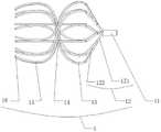
图6是本发明一种实施例在血管中的植入部位结构示意图;6 is a schematic structural diagram of an implantation site in a blood vessel according to an embodiment of the present invention;
图7是本发明一种实施例的末端构型进行过渡圆弧化设计的结构示意图;FIG. 7 is a schematic structural diagram of the transition arc design of the end configuration according to an embodiment of the present invention;
图8是本发明一种实施例对末端构型进行软化结构处理的结构示意图;FIG. 8 is a schematic structural diagram of the softening structure process performed on the terminal configuration according to an embodiment of the present invention;
图9是本发明一种实施例的自对中回收部的立体结构示意图;9 is a schematic three-dimensional structure diagram of a self-centering recovery part according to an embodiment of the present invention;
图10是本发明一种实施例的自对中回收部的剖面结构示意图;10 is a schematic cross-sectional structure diagram of a self-centering recovery part according to an embodiment of the present invention;
图11是本发明实施例1的立体结构示意图;FIG. 11 is a schematic three-dimensional structure diagram of
图12是本发明实施例1的主视结构示意图;Fig. 12 is the front view structure schematic diagram of
图13是本发明实施例1的部分构件侧视结构示意图;Figure 13 is a schematic side view of the structure of some components of
图14是本发明一种实施例的末端构型不同形状的结构示意图;FIG. 14 is a schematic structural diagram of different shapes of end configurations according to an embodiment of the present invention;
图15是本发明实施例2的立体结构示意图;FIG. 15 is a schematic three-dimensional structure diagram of
图16是本发明实施例2的主视结构示意图;Fig. 16 is the front view structure schematic diagram of
图17是本发明实施例3的立体结构示意图;FIG. 17 is a schematic three-dimensional structure diagram of
图18是本发明实施例3的主视结构示意图;Fig. 18 is the front view structure schematic diagram of
图19是本发明实施例4的立体结构示意图;FIG. 19 is a schematic three-dimensional structure diagram of
图20是本发明实施例4的主视结构示意图;Fig. 20 is the front view structure schematic diagram of
图21是本发明实施例5的立体结构示意图;FIG. 21 is a schematic three-dimensional structure diagram of Embodiment 5 of the present invention;
图22是本发明实施例5的主视结构示意图;Fig. 22 is the front view structure schematic diagram of Embodiment 5 of the present invention;
图23是本发明实施例5的侧视结构示意图。FIG. 23 is a schematic side view of the structure of Embodiment 5 of the present invention.
具体实施方式Detailed ways
下面结合附图,对本发明的较优的实施例作进一步的详细说明。The preferred embodiments of the present invention will be further described in detail below with reference to the accompanying drawings.
针对现有技术的缺点,如何同时兼顾开放式和封闭框架式的滤器优点,最大程度延长滤器安全回收时间窗,并且确保滤器在体内的稳定性是一个亟待解决的难题,因此,本例旨在提供一种新型的可回收的腔静脉滤器,在保证所述腔静脉滤器对血栓高效拦截性能下,具有长时间可回收操作窗口时间,植入体内不易移位,并且可反复回收和释放、精确定位,方便放置和回收。该腔静脉滤器可由金属或高分子材料等制成,优选采用一个整体的镍钛合金管进行切割定型而成,或优选采用记忆合金丝、线、带编制等连接而成。In view of the shortcomings of the prior art, how to take into account the advantages of both open and closed frame filters, maximize the safe recovery time window of the filter, and ensure the stability of the filter in vivo is an urgent problem to be solved. Therefore, this example aims to A new type of recyclable vena cava filter is provided, which has a long recyclable operation window time while ensuring the efficient interception performance of the vena cava filter on thrombus, and is not easy to be displaced when implanted in the body, and can be repeatedly recovered and released with high precision. Positioned for easy placement and recycling. The vena cava filter can be made of metal or polymer materials, etc., and is preferably formed by cutting and shaping an integral nickel-titanium alloy tube, or preferably connected by memory alloy wires, wires, tapes, and the like.
实施例1:Example 1:
如图1至图13所示,本例提供一种可回收的腔静脉滤器,包括:回收部11和自所述回收部11发出的至少3根构造杆1,所述至少3根构造杆1通过弯曲定型形成至少两个血栓过滤网、两个支撑盘以及一个末端构型16,其中,一个血栓过滤网设置于所述回收部11和一个支撑盘之间,另一个血栓过滤网设置于两个支撑盘之间的腰部,所述末端构型16设置于另一个支撑盘远离所述血栓过滤网的一端,所述末端构型16包括多个相互游离的末端,多个相互游离的末端向所述腔静脉滤器的中轴线倾斜弯曲聚拢。所述支撑盘的径向宽度优选大于所述血栓过滤网的径向宽度使得所述血栓过滤网不接触血管壁3。本例所述可回收的腔静脉滤器简称腔静脉滤器或滤器。本例所述腔静脉滤器的中轴线也可以简称轴线。As shown in FIGS. 1 to 13 , this example provides a retrievable vena cava filter, comprising: a
本例所支撑盘的径向宽度大于所述血栓过滤网的径向宽度,即所述第一支撑盘13和第二支撑盘15的径向宽度大于所述第一血栓过滤网12和第二血栓过滤网14的径向宽度,这样的设计好处在于能够使得所述第一血栓过滤网12和第二血栓过滤网14不会直接接触血管壁3(远离血管壁3),能够有效延长所述腔静脉滤器的安全回收时间窗。The radial width of the supported disk in this example is larger than the radial width of the thrombus filter, that is, the radial width of the
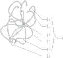
更为具体的,如图11至图13所示,本例沿所述腔静脉滤器中轴线依序设置的回收部11、第一血栓过滤网12、第一支撑盘13、第二血栓过滤网14、第二支撑盘15以及末端构型16,其中,所述回收部11的一端同第一血栓过滤网12相连接,所述回收部11的另一端为连接部;所述第一支撑盘13的一端连接至所述第一血栓过滤网12,所述第一支撑盘13的另一端收口连接至所述第二血栓过滤网14;所述第二支撑盘15的一端收口连接至所述第二血栓过滤网14,所述第二支撑盘15的另一端开放连接至所述末端构型16;所述第一血栓过滤网12分布在所述回收部11和第一支撑盘13之间,所述第二血栓过滤网14分布所述第一支撑盘13和第二支撑盘15之间的收口的腰部。More specifically, as shown in FIGS. 11 to 13 , in this example, the
进一步的,本例还可以优选包括第三血栓过滤网,所述第三血栓过滤网视具体情况决定是否设置,可以类似于所述第二血栓过滤网14那样来设置,用于增强其过滤效果;所述回收部11的另一端为连接部,该连接部优选为勾状或螺纹等多种形态的易连接部,便于回收。Further, this example may also preferably include a third thrombus filter, and the third thrombus filter may be set according to specific conditions, and may be set similarly to the
如图13所示,本例第一血栓过滤网12由多根所述构造杆1在所述回收部11和第一支撑盘13之间弯曲形成圆锥曲面过滤网,其中多根构造杆1汇集的一端连接至所述回收部11,另一端发散弯曲式连接至所述第一支撑盘13并顺滑延伸连接,每根构造杆1之间相互间隔,以形成弯曲伞骨状的过滤网格,便于提高血栓过滤效果。As shown in FIG. 13 , the
也就是说,本例优选由一端约束汇聚,另一端半开放整体结构,构成笼状双盘结构,对所述腔静脉滤器整体径向方向给予约束,所述腔静脉滤器具有适中性,当所述腔静脉滤器植入下腔静脉经时,可以有效避免器械倾斜,导致回收部贴近血管壁,无法回收现象,加强其回收性能。That is to say, in this example, one end is preferably constrained to converge, and the other end is a semi-open integral structure to form a cage-like double-disk structure, which constrains the overall radial direction of the vena cava filter. When the vena cava filter is implanted in the inferior vena cava meridian, the device can be effectively prevented from tilting, which causes the recovery part to be close to the vessel wall and cannot be recovered, thereby enhancing its recovery performance.
本例所述腔静脉滤器可从颈静脉或股静脉入路植入,植入时将所述腔静脉滤器收至输送鞘中,送达目标位置,回撤管释放后器械,由于器械使用具有记忆材料制成,释放后恢复原形状膨胀,第一支撑盘13和第二支撑盘15由内向外压迫血管,血管形成两个凸起部位,血管对所述腔静脉滤器形成反向的夹握力,所述腔静脉滤器获得有效的固定力,所述腔静脉滤器具有可靠的定位能力,避免植入滤器的沿血管轴线的移位,如获得更强的定位,可辅助采用在支撑盘设置尖凸状固定锚结构。本例采用双盘支撑结构,有效防止滤器的歪斜、偏移和移位,结构上保证所述腔静脉滤器的轴线同目标血管的轴一致重合,精确定位。The vena cava filter in this example can be implanted through the jugular vein or femoral vein. When implanting, the vena cava filter is received into the delivery sheath and delivered to the target position. After the retraction tube is released, the device has The vena cava filter is made of memory material. After release, the original shape is restored. The
本例采用整体半开放结构,所述构造杆1呈正或反“S”形,血管对前后的第一支撑盘13和第二支撑盘15的夹握力,通过所述构造杆1的“S”构型进行传递,形成相互支撑,进而能够自适应目标血管压力环境,自调整支撑盘的大小和形状,形成合适的滤器支撑力,防止过大的支撑力对血管形成较大的压力,过度刺激血管。在此基础上,即使第一支撑盘13和第二支撑盘15被新生内膜包裹,由于组成支撑盘的构造杆1没有逆向的分叉结构,即不存在分支向主支方向的分叉结构,在近端回收部11上加载一定的回收力,随着所述构造杆1变形,就可以将已有内皮化的所述腔静脉滤器从血管内膜完整抽离出来,避免对血管壁3的撕裂,得以有效延长所述腔静脉滤器的回收时间。This example adopts an overall semi-open structure, and the
如图1所示,滤器在植入人体后,以血管壁3接触的部件,不可避免存在一定程度的内皮化现象,若滤器构造杆1被新生内膜包裹,构造杆1与血管壁3形成一体,构造杆1将无法从血管壁拔出,只能强行将覆盖构造杆的血管新生内膜2撕裂,才可能将滤器取出,如果新生内膜2增生较厚无法撕裂,滤器就无法取出,针对该问题,本例采用创新的结构设计,如图2所示,优化滤器的结构和保持所述构造杆1一端游离,滤器回收时,构造杆1从血壁的新生内膜2中抽出,不采用撕裂的方式,采用从新生内膜2中取出构造杆1,降低滤器取出的难度,延长滤器的可回收时间,其中滤器的基本单元,所述构造杆1在同血管壁3接触部位被新生内膜2的增生组织包裹正常血管。As shown in Fig. 1, after the filter is implanted into the human body, the parts in contact with the
本例所述构造杆1在同血管壁3直接接触部位被新生内膜2的增殖组织包裹,构造杆1没有逆方向分叉结构,受到回收方向的力,变形拉直,从增殖组织内抽出而与增殖组织分离,血管壁3只留下构造杆1的占位空腔4,如图2所示,避免对血管新生内膜撕裂和易于取出滤器。In this example, the
本例所述腔静脉滤器包括由自回收部11上发出远离中轴线的至少3根构造杆1,每1根构造杆1如图3所示呈正反“S” 形弯曲定型形成,或正反“3”形弯曲定型形成,在不同的位置形成不同的区域段,形成不同的功能区段,如前述的支撑盘、血栓过滤网和末端构型16,也就是说,本例所述回收部11为用于实现回收的连接部,而所述构造杆1为如图1至图3所示的所述腔静脉滤器的基本单元,所述构造杆1包括第一血栓过滤网12、第一支撑盘13、第二血栓过滤网14、第二支撑盘15以及末端构型16,不同的构件名称是构造杆1位于不同部位用于实现不同功能的一个区间段划分,依序排列,在结构上没有明显的区分标记,所述腔静脉滤器包括多条构造杆1一体连续延伸、变形构型组成,多个所述末端构型16的形状和长度可以根据实际情况的不同的自定义设置或调整,即其形状和长度可以不相同,即所述末端构型16为所述构造杆1的具有不同形状和长度的末端。The vena cava filter in this example includes at least three
其中,本例所述第一支撑盘13和第二支撑盘15与血管壁3相接触,第一血栓过滤网12和第二血栓过滤网14不与血管壁3直接接触,构造杆1的一端相聚拢汇集于回收部11,另一端在释放状态下处于游离状态。In this example, the
如图3所示,单独一条构造杆1投影到滤器轴线平面或平行轴线平面,沿所述腔静脉滤器的中轴线211左右交叉弯曲,在垂直于所述腔静脉滤器的中轴线的平面212上下交错弯曲,单独的构造杆1在所述腔静脉滤器的中轴线平面或平行轴线平面投影呈“S”形,或反“S”形。As shown in FIG. 3 , a single
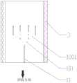
如图4和图5所示,本例每一根构造杆1从所述回收部11向远离所述回收部11的方向分叉成至少2根分支,形成单级或多级分叉形构造杆1,在第一次形成接触血管壁的支撑盘前,从回收部11发出的构造杆1和分叉形构造杆1相互交叉或编织形成网格结构的血栓过滤网,所述网格结构包括菱形或圆形。As shown in FIG. 4 and FIG. 5 , in this example, each
比如:构造杆1包括回收部11的主分支和次级分支构造杆,其中次级分支构造杆包括一级分支构造杆101和二级分支构造杆1001,所述二级分支构造杆1001为一级分支构造杆101的分支,进而形成整体的多级分叉形构造杆1。每一根构造杆1从回收部向远端任意位置可分叉成2根或2根以上次级分支构造杆,形成单根或多级、多个小的一级分支构造杆101和二级分支构造杆1001;构造杆1在同血管壁3直接接触部位被增殖组织包裹,从分支向主干方向定义为正方向,相反定义为逆方向,滤器承受正方向的回收拉力,所述构造杆1没有逆方向分叉结构,在受到回收部的拉力,变形拉直,至少2条二级分支构造杆1001向一级分叉构造杆101正方向收敛位移,至少2条次级分支构造杆向所述回收部11的主分支正方向收敛位移,进而滤器从增殖组织内抽出分离,血管壁3内仅留下所述构造杆1占位空腔,避免对静脉血管的撕裂。本例多个一级分支构造杆101和二级分支构造杆1001相互交叉实现过滤结构可以直接当成第一血栓过滤网12。For example, the
如图6所示,本例提供的所述腔静脉滤器,置于肾静脉9和髂静脉8之间的下腔静脉7位置,放置方向可以顺着血流方向或逆着血流方向,可采用介入方法经颈静脉或股静脉,用输送/回收鞘管进行定位、释放、适时从体内回收。在植入期间,在滤器和血管壁接触位置会产生新生内膜2的增生组织,包裹所述腔静脉滤器的支撑盘。As shown in Figure 6, the vena cava filter provided in this example is placed at the position of the inferior vena cava 7 between the renal vein 9 and the iliac vein 8, and the placement direction can be along the blood flow direction or against the blood flow direction, and can be Through the jugular or femoral vein, the delivery/retrieval sheath is used to locate, release, and retrieve from the body in a timely manner. During implantation, proliferative tissue of the
如图7所示,本例所述末端构型16远离所述第二支撑盘15的一端设置为过渡圆弧化末端60,所述过渡圆弧化末端包括圆球状末端或水滴状末端;或,如图8所示,所述末端构型16远离所述第二支撑盘15的一端设置为过渡软化末端70或过渡软化末端70’,所述过渡软化末端70或过渡软化末端70’包括依次连接的过渡段和圆状末端,所述过渡段为逐渐变细或包括绕制弹簧的软化过渡段。As shown in FIG. 7 , the end of the
为进一步避免释放、回收和植入过程中刺伤血管,避免自由末端构型对血管壁刺伤,同时减少滤器回收阻力,如图7所示,本例对所述末端构型16做一个圆滑化处理,如过渡圆弧化末端60通过二次加工尾部圆球化,其尾端形状可以呈圆球和水滴状等过渡圆弧化,进一步的,还可以连接一个球状物,球状物可以为金、钨、铂等金属和含前述金属的合金以及聚合物等。In order to further avoid stabbing the blood vessel during the release, recovery and implantation process, avoid stabbing the blood vessel wall by the free end configuration, and reduce the filter recovery resistance, as shown in FIG. For example, the
再进一步的,如图8所示,本例对所述末端构型16做一个软化结构处理,如过渡软化末端70的尾部采用由逐渐变细的过渡段76、金属弹簧绕制成为软化过渡段77以及最前端的圆帽78,避免刺伤血管。还可以对末端构型16做一个锥度细化,如过渡软化末端70’的尾部为逐渐变细的过渡段76’,末端79为小圆状,通过这种尾端直径的细和/或软设计,进而能够有效避免刺伤血管。Further, as shown in FIG. 8 , the
如图9和图10所示,本例所述回收部11为包括对中伞911、连接柱912和内螺纹913的自对中回收部11,所述对中伞911通过所述连接柱912连接至所述第一血栓过滤网12,其中,所述对中伞911为底部开口的圆锥状构件,所述圆锥状构件的圆锥开口方向远离所述第一血栓过滤网12,所述圆锥状构件的圆锥面设置有沿轴线间隔分布的开口槽;所述连接柱912为一个圆柱体,所述内螺纹913为设置于所述连接柱912内的螺纹结构,在图9和图10中,仅仅标识出其位置,没有将螺纹画出。As shown in FIG. 9 and FIG. 10 , the
也就是说,除了图11和图12的这种基本的回收部11的设计之外,本例还可以优选采用图9和图10所示的优选设计进而实现了自对中的滤器回收部结构,所述回收部11位于滤器的一端同所述第一血栓过滤网12连接,由对中伞911、连接柱912、内螺纹913组成,其中对中伞911为一底部开口的圆锥状,圆锥开口方向远离滤器,圆锥面有沿轴线间隔分布的开口槽,避免过多干扰血流的流动,同时也便于带螺栓头的弹簧软轴的进入。所述连接柱912为一个圆柱体且与滤器的第一血栓过滤部12连接,所述内螺纹913处于所述连接柱912内,用于滤器的拆卸,连接。因此,本例提供了两种回收方式,采用前端带螺栓头的弹簧软轴进入圆锥形状的对中伞911较大的区域,可顺利同通过所述内螺纹912连接,方便滤网的回收;或,采用金属圈套器,很容易定位到所述对中伞911外圆锥面,拉紧固定,也能够方便滤器的回收。That is to say, in addition to the basic design of the
值得一提的是,本例所述第一支撑盘13为类圆柱笼体,包括由所述第一血栓过滤网12的一端延伸的多条所述构造杆1,所述第二血栓过滤网14另一端延伸弯曲收口于第一支撑盘13和第二支撑盘15之间的腰部,所述第一支撑盘13和/或第二支撑盘15上设置远离所述腔静脉滤器中心轴并向外辐射的尖刺状固定锚,所述尖刺状固定锚的向外辐射方向为远离所述回收部11的方向,从而进一步避免所述腔静脉滤器的移位,并加强所述腔静脉滤器的定位能力。It is worth mentioning that the
同样值得一提的是,本例所述第二血栓过滤网14由多根构造杆1绕所述腔静脉滤器的中心轴并偏离预设距离的轴线,所述第一血栓过滤网12和第二血栓过滤网14之间弯曲形成空间交错过滤网格,也就是说,本例所述第二血栓过滤网14由各构造杆1绕所述腔静脉滤器的中心轴并偏离预设距离轴线,该预设距离可以根据实际设计或使用需求进行自定义设计和调整,使得所述第二血栓过滤网14在所述第一支撑盘13和第二支撑盘15之间弯曲形成空间交错形成,投影到垂直于轴线的平面呈现过滤网格状,该第二血栓过滤网14的过滤网格状轴线与所述第一血栓过滤网12的过滤网格轴线交错设置,便于更进一步提高血栓过滤效果。It is also worth mentioning that the
此外,本例所述第二支撑盘15由多条构造杆1弯曲形成,形成呈类“U”形开口笼体,即半开口式笼体结构,该第二支撑盘15的一端由所述第一支撑盘13和第二支撑盘15之间的腰部的第二血栓过滤网14延伸弯曲形成,另一端与所述末端构型16顺序相连,同样的,本例所述第一支撑盘15上优选设置远离所述腔静脉滤器的中心轴向外辐射的小的尖刺状固定锚,所述尖刺状固定锚的方向为远离所述回收部1的方向,进而能够起到避免所述腔静脉滤器的移位,并加强所述腔静脉滤器的定位能力。In addition, the
本例可以通过调整所述构造杆1的几何结构尺寸可调整所述腔静脉滤器的支撑力,如构造杆1的宽度、厚度、与血管壁3的贴合长度、弯曲的形状以及弯曲角度。通过分别调整第一支撑盘13和第二支撑盘15的直径尺寸,获得不同的支撑力,所述第一支撑盘13和第二支撑盘15也可以采用不同的直径,以适应血管的实际直径形状。In this example, the support force of the vena cava filter can be adjusted by adjusting the geometrical dimensions of the
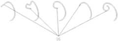
本例所述末端构型16的一端由所述第二支撑盘15延续相连,另一端呈游离,弯曲形成向轴线弯折弧或内卷,如图14所示,所述末端构型16延长构成辅助的血栓过滤网,有效拦截静脉血栓。如加强血栓过滤能力,除了增加构造杆1的数量外,构造杆1可以在第一血栓过滤网12处采用弯曲、绕“O”、“8”形、邻近或非邻近构造杆交错编织等形式,增加血栓过滤网的网格密度,进一步提高血栓捕捉效能。In this example, one end of the
本例所述第二血栓过滤网14通过多根构造杆1空间交错形成具有拉伸变形和收敛成束性能的血栓过滤结构。即所述第二血栓过滤网14处的多条构造杆1空间交错,不能形成牢固稳定的交叉结构,具有拉伸变形、收敛成束性能,方便回收入鞘管性能。末端构型16本身有一定的捕捉血栓的能力,如延长汇集可以作为辅助的第三层血栓过滤层存在。因此该腔静脉滤器具有可以大范围调整的血栓过滤结构,配合实际临床需求。In this example, the second
本例所述末端构型16相互自由游离,具有向轴线倾斜弯曲聚拢形状,有效避免滤器释放过程中,在离开输送鞘管端口瞬间,所述末端构型16因释放无鞘管约束,瞬间恢复记忆尺寸出现向外弹跳效应,容易刺伤血管壁。因此,本例所述末端构型16采用向轴线弯曲聚拢形状,释放瞬间接触血管向内弯曲的圆弧段,避免刺伤血管壁,如图14所示,本例所述末端构型16的一端与所述第二支撑盘15延续相连,所述末端构型16的另一端向轴线折弯、双折弯或内卷游离,这种弯曲形成向轴线弯折弧或内卷的末端构型16不同结构形状,均向轴线倾斜、变形和内拢,保证了血栓过滤的基础上,还能够有效避免自由末端构型对血管壁3刺伤等弊端。In this example, the
实施例2:Example 2:
如图15和图16所示,在实施例1的基础上,本例对部分部件进行了结构上的优化设计,本例所述腔静脉滤器每一根构造杆1从回收部11向远端任意位置可分叉成2根或2根以上细的分支构造杆,形成单个或多个小的分叉形构造杆,在第一次形成接触血管壁3的第一支撑盘13前,从回收部11发出的构造杆1和分叉形成的分支小构造杆,相互交叉或编织形成菱形或圆形等网格结构,形成更有利于血栓过滤的第一血栓过滤网12,第一血栓过滤网12远离血管壁3,与血管壁3保持一定的距离,避免血栓内膜细胞爬附增殖到所述第一血栓过滤网12。As shown in FIGS. 15 and 16 , on the basis of Example 1, some components are optimized in structure in this example. Each
除第一血栓过滤网12可通过构造杆1形成稳定牢靠交叉、编织成血栓过滤网外,第二血栓过滤网14、第一支撑盘13、第二支撑盘15和末端构型16,保持相互自由游离状态,向轴线弯曲倾斜聚拢。在回收力的作用下,整体同步收敛成束,从血管壁中抽出,Except that the first
同样的,本例所述腔静脉滤器由自回收部11上发出远离轴线的至少3根所述构造杆3,呈正反“S”或正反“3”形弯曲定型形成,在不同的位置形成大小不同、形状不同的区域段,形成不同的功能区段,如前述的支撑盘、血栓过滤网和末端构型16等。在本实施例中,第一血栓过滤网12还可由发自所述回收部11的主支121向外辐射,在适当位置出现至少有2个第一分支122和第二分支123,第一分支122和第二分支123汇集于第一支撑盘13的起始位置,由主支121第一分支122和第二分支123构成第一血栓过滤网12,密集的网格增加滤器的支撑力,增加所述腔静脉滤器的血栓过滤效果。本例所述第一血栓过滤网12的直径大小优选不超过所述第一支撑盘13的直径,通常小1~8mm,这样的设计效果最佳。Similarly, the vena cava filter in this example is formed by at least three
实施例3:Example 3:
如图17和图18所示,在实施例1的基础上,本例对部分部件进行了结构上的优化设计,与实施例1不同的是,本例从回收部11上发出远离其中轴线的构造杆1呈正或反“3”形态,分别围成两个第一血栓过滤网12、第一支撑盘13、第二血栓过滤网14、第二支撑盘15和末端构型16;所有构造杆1的末端构型16相互游离,向所述腔静脉滤器的中轴线内收聚拢。As shown in Fig. 17 and Fig. 18 , on the basis of
本例所述第一血栓过滤网12由多条构造杆1在回收部11和第一支撑盘13弯曲形成圆锥曲面过滤网,其中包括多条构造杆汇集一端连接回收部,另一端辐射发散同第一支撑盘13顺滑延伸连接,每个构造杆1相互间隔,第一血栓过滤部13投影在垂直于轴线平面上呈“伞”骨架,形成过滤网格。所述末端构型16由第二支撑盘15延续弯曲形成,一端呈游离状,多条末端构型16可以形成一个辅助的第三血栓过滤网。In this example, the first
本例所述构造杆1采用正或反“3”形结构,这种结构能够更加便于所述新生内膜2增生组织在已经爬附所述腔静脉滤器情况下,利于构造杆1从内膜抽出,降低所述腔静脉滤器的回收阻力,极大地增加所述腔静脉滤器的可回收时间。In this example, the
实施例4:Example 4:
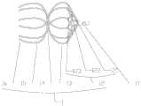
如图19和图20所示,在实施例1的基础上,本例对部分部件进行了结构上的优化设计,本例从回收部11上发出远离其中轴线的构造杆1呈正或反“S”形态,分别围成两个第一血栓过滤网12、第一支撑盘13、第二血栓过滤网14、第二支撑盘15和末端构型16,所有构造杆1的末端构型16相互游离,向所述腔静脉滤器的中轴线内收聚拢。与实施例1不同的是,本例所述的构造杆1的中轴线与所述腔静脉滤器的中轴线之间设计存在预设偏转角度和预设距离,所述预设偏转角度可以根据实际需要进行自定义设计和调整,所述预设距离也可以根据实际需要进行自定义设计和调整,所述构造杆1的中轴线与所述腔静脉滤器的中轴线之间的预设偏转角度优选为5~45度之间,偏转方向为顺逆时针,这样的设计是在行业内没出现过的,经试验证明,可以有效提高所述腔静脉滤器对血管的自适应性。As shown in Figures 19 and 20, on the basis of Example 1, this example has carried out structural optimization design for some components. In this example, the
实施例5:Example 5:
如图21至图23所示,在实施例1的基础上,本例对部分部件进行了结构上的优化设计,本例从回收部11上发出分别弯曲围成两个第一血栓过滤网12、第一支撑盘13、第二血栓过滤网14、第二支撑盘15和末端构型16,所有构造杆1的末端构型16相互游离,向所述腔静脉滤器的中轴线内收聚拢。与实施例1不同的是,本例每条构形杆1从回收部11向远端任意位置至少分叉成2根分支进而组成分叉结构,形成小的构造杆,小的构造杆远端保持游离,如图21至图23所示所示,主支121自回收端发出,在适宜处分叉为至少两个第一分支122,甚至于每一个第一分支122可以进一步分叉为至少两个第二分支;本例采用多条多级分叉结构可以增加滤器捕捉血栓的能力,并有效提高了所述腔静脉滤器对血管的支撑力。As shown in FIGS. 21 to 23 , on the basis of
综上所述,本例由至少3根构造杆1通过弯曲定型形成至少两个血栓过滤网、两个支撑盘以及一个末端构型16,进而形成一端约束汇聚,另一端半开放的笼状双盘的整体结构,将本例植入下腔静脉经可以有效避免器械倾斜,并输送导管到达目标位置,释放后根据其形状膨胀使得两个支撑盘由内向外压迫血管,血管形成两个凸起部位,血管对所述腔静脉滤器形成反向的压力,使得所述腔静脉滤器获得有效的固定力,通过本例的结构设计能够有效防止所述腔静脉滤器的歪斜、偏移和移位等问题,在结构上保证所述腔静脉滤器的轴线同目标血管的轴线一致重合,并有效提高了血栓过滤效果。To sum up, in this example, at least three
在此基础上,本例还通过其优化的结构设计,使得所述腔静脉滤器能够针对目标血管的压力环境拥有了自适应能力,支撑盘得以依据血管壁的压力和血管变化的血压实现对支撑盘的大小和形状的调整,提高了所述腔静脉滤器的支撑适应能力,防止过大的支撑力对血管形成过度刺激或损伤,大幅度提高了产品的安全性能;并且,还能够有效延缓血管对所述腔静脉滤器的内皮化速度,有效延长了所述腔静脉滤器的安全植入时间,延长其安全回收时间窗。On this basis, through its optimized structural design, the vena cava filter has the ability to adapt to the pressure environment of the target blood vessel, and the support plate can support the blood vessel wall according to the pressure of the blood vessel wall and the blood pressure of the blood vessel. The adjustment of the size and shape of the disc improves the support adaptability of the vena cava filter, prevents excessive stimulation or damage to the blood vessels caused by excessive supporting force, and greatly improves the safety performance of the product; and can effectively delay the blood vessels. The endothelialization speed of the vena cava filter effectively prolongs the safe implantation time of the vena cava filter and prolongs the safe recovery time window.
以上内容是结合具体的优选实施方式对本发明所作的进一步详细说明,不能认定本发明的具体实施只局限于这些说明。对于本发明所属技术领域的普通技术人员来说,在不脱离本发明构思的前提下,还可以做出若干简单推演或替换,都应当视为属于本发明的保护范围。The above content is a further detailed description of the present invention in combination with specific preferred embodiments, and it cannot be considered that the specific implementation of the present invention is limited to these descriptions. For those of ordinary skill in the technical field of the present invention, without departing from the concept of the present invention, some simple deductions or substitutions can be made, which should be regarded as belonging to the protection scope of the present invention.
Claims (10)
Translated fromChinesePriority Applications (2)
| Application Number | Priority Date | Filing Date | Title |
|---|---|---|---|
| CN202010651888.0ACN111658224B (en) | 2020-07-08 | 2020-07-08 | A recyclable vena cava filter |
| CN202110753681.9ACN113331988B (en) | 2020-07-08 | 2020-07-08 | Recyclable vena cava filter |
Applications Claiming Priority (1)
| Application Number | Priority Date | Filing Date | Title |
|---|---|---|---|
| CN202010651888.0ACN111658224B (en) | 2020-07-08 | 2020-07-08 | A recyclable vena cava filter |
Related Child Applications (1)
| Application Number | Title | Priority Date | Filing Date |
|---|---|---|---|
| CN202110753681.9ADivisionCN113331988B (en) | 2020-07-08 | 2020-07-08 | Recyclable vena cava filter |
Publications (2)
| Publication Number | Publication Date |
|---|---|
| CN111658224Atrue CN111658224A (en) | 2020-09-15 |
| CN111658224B CN111658224B (en) | 2021-08-20 |
Family
ID=72391500
Family Applications (2)
| Application Number | Title | Priority Date | Filing Date |
|---|---|---|---|
| CN202110753681.9AActiveCN113331988B (en) | 2020-07-08 | 2020-07-08 | Recyclable vena cava filter |
| CN202010651888.0AActiveCN111658224B (en) | 2020-07-08 | 2020-07-08 | A recyclable vena cava filter |
Family Applications Before (1)
| Application Number | Title | Priority Date | Filing Date |
|---|---|---|---|
| CN202110753681.9AActiveCN113331988B (en) | 2020-07-08 | 2020-07-08 | Recyclable vena cava filter |
Country Status (1)
| Country | Link |
|---|---|
| CN (2) | CN113331988B (en) |
Families Citing this family (1)
| Publication number | Priority date | Publication date | Assignee | Title |
|---|---|---|---|---|
| CN119074308A (en)* | 2023-12-06 | 2024-12-06 | 上海蓝脉医疗科技有限公司 | Vena cava filters and filter retrieval systems |
Citations (5)
| Publication number | Priority date | Publication date | Assignee | Title |
|---|---|---|---|---|
| US6059825A (en)* | 1992-03-05 | 2000-05-09 | Angiodynamics, Inc. | Clot filter |
| US20080275489A1 (en)* | 2007-05-01 | 2008-11-06 | Thomas Frank Kinst | Removable medical filter |
| CN105722474A (en)* | 2013-11-13 | 2016-06-29 | 柯惠有限合伙公司 | Galvanically assisted attachment of medical devices to thrombus |
| CN106725997A (en)* | 2016-12-22 | 2017-05-31 | 北京华脉泰科医疗器械有限公司 | Vena cava filter and its production method |
| CN107928839A (en)* | 2018-01-04 | 2018-04-20 | 科塞尔医疗科技(苏州)有限公司 | A kind of degradable vena cava filter in part |
Family Cites Families (19)
| Publication number | Priority date | Publication date | Assignee | Title |
|---|---|---|---|---|
| US7018401B1 (en)* | 1999-02-01 | 2006-03-28 | Board Of Regents, The University Of Texas System | Woven intravascular devices and methods for making the same and apparatus for delivery of the same |
| US6146404A (en)* | 1999-09-03 | 2000-11-14 | Scimed Life Systems, Inc. | Removable thrombus filter |
| DE10000137A1 (en)* | 2000-01-04 | 2001-07-12 | Pfm Prod Fuer Die Med Ag | Implantate for closing defect apertures in human or animal bodies, bearing structure of which can be reversed from secondary to primary form by elastic force |
| US6482222B1 (en)* | 2000-07-11 | 2002-11-19 | Rafael Medical Technologies Inc. | Intravascular filter |
| WO2002102280A2 (en)* | 2001-06-18 | 2002-12-27 | Rex Medical, L.P. | Removable vein filter |
| US8377092B2 (en)* | 2005-09-16 | 2013-02-19 | Cook Medical Technologies Llc | Embolic protection device |
| US20070239199A1 (en)* | 2006-03-31 | 2007-10-11 | Swaminathan Jayaraman | Inferior vena cava filter |
| US20080275490A1 (en)* | 2007-05-01 | 2008-11-06 | Fleming James A | Medical filter with partial baskets |
| JP5767976B2 (en)* | 2009-02-03 | 2015-08-26 | メリット・メディカル・システムズ・インコーポレーテッド | Transcutaneous recoverable vascular filter |
| EP2558005B1 (en)* | 2010-04-13 | 2022-03-30 | MIVI Neuroscience, Inc | Embolectomy devices for treatment of acute ischemic stroke condition |
| US8734480B2 (en)* | 2011-08-05 | 2014-05-27 | Merit Medical Systems, Inc. | Vascular filter |
| US9060886B2 (en)* | 2011-09-29 | 2015-06-23 | Covidien Lp | Vascular remodeling device |
| WO2014042825A1 (en)* | 2012-09-12 | 2014-03-20 | Boston Scientific Scimed, Inc. | Fixation anchor design for an occlusion device |
| US9314248B2 (en)* | 2012-11-06 | 2016-04-19 | Covidien Lp | Multi-pivot thrombectomy device |
| CA3003232C (en)* | 2015-10-26 | 2024-01-23 | Amnis Therapeutics Ltd. | Systems for thrombectomy |
| CN206576983U (en)* | 2016-11-21 | 2017-10-24 | 上海形状记忆合金材料有限公司 | A kind of vena cava filter |
| CN206621451U (en)* | 2016-12-22 | 2017-11-10 | 北京华脉泰科医疗器械有限公司 | Vena cava filter, double back receive vena cava filter |
| CN108283530A (en)* | 2017-03-07 | 2018-07-17 | 上海宏普医疗器械有限公司 | A kind of octopus type retrievable vena cava filter |
| CN110063814A (en)* | 2019-05-16 | 2019-07-30 | 山西职业技术学院 | A kind of calabash shape vena cava filter |
- 2020
- 2020-07-08CNCN202110753681.9Apatent/CN113331988B/enactiveActive
- 2020-07-08CNCN202010651888.0Apatent/CN111658224B/enactiveActive
Patent Citations (5)
| Publication number | Priority date | Publication date | Assignee | Title |
|---|---|---|---|---|
| US6059825A (en)* | 1992-03-05 | 2000-05-09 | Angiodynamics, Inc. | Clot filter |
| US20080275489A1 (en)* | 2007-05-01 | 2008-11-06 | Thomas Frank Kinst | Removable medical filter |
| CN105722474A (en)* | 2013-11-13 | 2016-06-29 | 柯惠有限合伙公司 | Galvanically assisted attachment of medical devices to thrombus |
| CN106725997A (en)* | 2016-12-22 | 2017-05-31 | 北京华脉泰科医疗器械有限公司 | Vena cava filter and its production method |
| CN107928839A (en)* | 2018-01-04 | 2018-04-20 | 科塞尔医疗科技(苏州)有限公司 | A kind of degradable vena cava filter in part |
Also Published As
| Publication number | Publication date |
|---|---|
| CN111658224B (en) | 2021-08-20 |
| CN113331988B (en) | 2022-12-27 |
| CN113331988A (en) | 2021-09-03 |
Similar Documents
| Publication | Publication Date | Title |
|---|---|---|
| US11690741B2 (en) | Vascular remodeling device | |
| CN106037863B (en) | Left auricle occluder and manufacturing method thereof | |
| CN108926371B (en) | Left auricle plugging device with closed-loop structure and assembly method thereof | |
| US7179274B2 (en) | Intravascular filter | |
| CN107126241B (en) | Biological cavity anchoring device capable of being completely recovered and repeatedly released | |
| US10939986B2 (en) | Inferior vena cava filter | |
| CN104736103A (en) | Fixation anchor design for an occlusion device | |
| CN105662646A (en) | Filter | |
| EP3232987A1 (en) | Biodegradable filter and support frame | |
| CN110169843B (en) | A lotus petal type double-layer point support recyclable vena cava filter and manufacturing method | |
| CN111658224A (en) | Recoverable vena cava filter | |
| CN106913392A (en) | Filter | |
| CN207220906U (en) | A kind of filter in implantable intravascular | |
| CN113116461A (en) | Thrombus taking device and thrombus taking system | |
| CN106725996A (en) | A kind of vena cava filter | |
| CN213993851U (en) | Recoverable vena cava filter | |
| CN206499550U (en) | A kind of vena cava filter | |
| CN205494081U (en) | Filter | |
| CN205494080U (en) | Filter | |
| CN112120828B (en) | A vena cava filter | |
| CN205494082U (en) | Filter | |
| CN105596115B (en) | Vena cava filter | |
| CN108143518B (en) | filter | |
| CN205494083U (en) | Filter | |
| CN114681107A (en) | An implantable lumen filter |
Legal Events
| Date | Code | Title | Description |
|---|---|---|---|
| PB01 | Publication | ||
| PB01 | Publication | ||
| SE01 | Entry into force of request for substantive examination | ||
| SE01 | Entry into force of request for substantive examination | ||
| GR01 | Patent grant | ||
| GR01 | Patent grant |