CN111658084A - Puncture dilator - Google Patents
Puncture dilatorDownload PDFInfo
- Publication number
- CN111658084A CN111658084ACN202010469886.XACN202010469886ACN111658084ACN 111658084 ACN111658084 ACN 111658084ACN 202010469886 ACN202010469886 ACN 202010469886ACN 111658084 ACN111658084 ACN 111658084A
- Authority
- CN
- China
- Prior art keywords
- tube body
- expansion
- stage
- primary
- puncture
- Prior art date
- Legal status (The legal status is an assumption and is not a legal conclusion. Google has not performed a legal analysis and makes no representation as to the accuracy of the status listed.)
- Granted
Links
Images


Classifications
- A—HUMAN NECESSITIES
- A61—MEDICAL OR VETERINARY SCIENCE; HYGIENE
- A61B—DIAGNOSIS; SURGERY; IDENTIFICATION
- A61B17/00—Surgical instruments, devices or methods
- A61B17/34—Trocars; Puncturing needles
- A61B17/3415—Trocars; Puncturing needles for introducing tubes or catheters, e.g. gastrostomy tubes, drain catheters
- A—HUMAN NECESSITIES
- A61—MEDICAL OR VETERINARY SCIENCE; HYGIENE
- A61B—DIAGNOSIS; SURGERY; IDENTIFICATION
- A61B17/00—Surgical instruments, devices or methods
- A61B17/34—Trocars; Puncturing needles
- A61B17/3417—Details of tips or shafts, e.g. grooves, expandable, bendable; Multiple coaxial sliding cannulas, e.g. for dilating
- A61B17/3421—Cannulas
- A—HUMAN NECESSITIES
- A61—MEDICAL OR VETERINARY SCIENCE; HYGIENE
- A61M—DEVICES FOR INTRODUCING MEDIA INTO, OR ONTO, THE BODY; DEVICES FOR TRANSDUCING BODY MEDIA OR FOR TAKING MEDIA FROM THE BODY; DEVICES FOR PRODUCING OR ENDING SLEEP OR STUPOR
- A61M29/00—Dilators with or without means for introducing media, e.g. remedies
- A—HUMAN NECESSITIES
- A61—MEDICAL OR VETERINARY SCIENCE; HYGIENE
- A61B—DIAGNOSIS; SURGERY; IDENTIFICATION
- A61B17/00—Surgical instruments, devices or methods
- A61B17/34—Trocars; Puncturing needles
- A61B17/3417—Details of tips or shafts, e.g. grooves, expandable, bendable; Multiple coaxial sliding cannulas, e.g. for dilating
- A61B17/3421—Cannulas
- A61B2017/3445—Cannulas used as instrument channel for multiple instruments
- A61B2017/3447—Linked multiple cannulas
- A—HUMAN NECESSITIES
- A61—MEDICAL OR VETERINARY SCIENCE; HYGIENE
- A61B—DIAGNOSIS; SURGERY; IDENTIFICATION
- A61B17/00—Surgical instruments, devices or methods
- A61B17/34—Trocars; Puncturing needles
- A61B17/3417—Details of tips or shafts, e.g. grooves, expandable, bendable; Multiple coaxial sliding cannulas, e.g. for dilating
- A61B17/3421—Cannulas
- A61B2017/3445—Cannulas used as instrument channel for multiple instruments
- A61B2017/3449—Cannulas used as instrument channel for multiple instruments whereby the instrument channels merge into one single channel
Landscapes
- Health & Medical Sciences (AREA)
- Life Sciences & Earth Sciences (AREA)
- Surgery (AREA)
- Heart & Thoracic Surgery (AREA)
- Public Health (AREA)
- Veterinary Medicine (AREA)
- Engineering & Computer Science (AREA)
- Biomedical Technology (AREA)
- General Health & Medical Sciences (AREA)
- Animal Behavior & Ethology (AREA)
- Molecular Biology (AREA)
- Medical Informatics (AREA)
- Nuclear Medicine, Radiotherapy & Molecular Imaging (AREA)
- Pathology (AREA)
- Gastroenterology & Hepatology (AREA)
- Anesthesiology (AREA)
- Hematology (AREA)
- Surgical Instruments (AREA)
Abstract
Description
Translated fromChinese技术领域technical field
本发明涉及医疗器械技术领域,具体地,涉及一种穿刺扩张器。The invention relates to the technical field of medical devices, in particular to a puncture dilator.
背景技术Background technique
经皮穿刺目前已广泛应用于临床,穿刺扩张器主要用于对体表的穿刺部位进行扩张,以便于介入器械的输送,穿刺扩张器一般包括管体,管体的远端逐渐收敛变细,便于引导穿入,管体的近端安装有柄部,便于持握或与其他装置相配合。Percutaneous puncture has been widely used in clinical practice. The puncture dilator is mainly used to expand the puncture site on the body surface to facilitate the delivery of interventional instruments. The puncture dilator generally includes a tube body, and the distal end of the tube body gradually converges and becomes thinner. It is convenient to guide and penetrate, and the proximal end of the tube body is provided with a handle, which is convenient for holding or matching with other devices.
现有技术中,采用多根不同尺寸的管体进行扩张,直至扩张到所需要的程度,不仅需要多次穿刺,增加穿刺次数、步骤和时间,而且还存在较大的风险,容易导致较多血液流失的现象。In the prior art, multiple tubes of different sizes are used for expansion until the expansion reaches the required degree, which not only requires multiple punctures, increasing the number of punctures, steps and time, but also involves a greater risk, which is likely to cause more punctures. The phenomenon of blood loss.
发明内容SUMMARY OF THE INVENTION
针对现有技术的不足,本发明提供一种穿刺扩张器。In view of the deficiencies of the prior art, the present invention provides a puncture dilator.
本发明公开的一种穿刺扩张器,包括:一级管体、二级管体及管体扩张件,二级管体设置于一级管体的近端,管体扩张件的远端活动设置于二级管体内;二级管体由弹性材质制成;其中,通过管体扩张件在二级管体内运动,实现二级管体的扩张。The invention discloses a puncture dilator, comprising: a primary tube body, a secondary tube body and a tube body expansion piece, the secondary tube body is arranged at the proximal end of the primary tube body, and the distal end of the tube body expansion piece is movably arranged in the secondary tube body; the secondary tube body is made of elastic material; wherein, the expansion of the secondary tube body is realized by moving the tube body expansion piece in the secondary tube body.
根据本发明的一实施方式,一级管体包括头部及一级管身,头部设置于一级管身远端,二级管体套设于一级管身,且二级管体远端抵接头部近端;管体扩张件活动套设于一级管身。According to an embodiment of the present invention, the primary pipe body includes a head and a primary pipe body, the head is disposed at the distal end of the primary pipe body, the secondary pipe body is sleeved on the primary pipe body, and the secondary pipe body is far away from the primary pipe body. The end abuts the proximal end of the joint part; the pipe body expansion piece is movably sleeved on the primary pipe body.
根据本发明的一实施方式,二级管体与头部成第一角度设置,第一角度为钝角或平角(即二级管体与头部之间的夹角为钝角或平角)。According to an embodiment of the present invention, the diode body and the head are arranged at a first angle, and the first angle is an obtuse angle or a flat angle (ie, the angle between the diode body and the head is an obtuse or flat angle).
根据本发明的一实施方式,二级管体的近端设有锥形孔。According to an embodiment of the present invention, the proximal end of the diode body is provided with a tapered hole.
根据本发明的一实施方式,管体扩张件包括三级管体,三级管体活动套设于一级管身。According to an embodiment of the present invention, the tube body expansion member includes a tertiary tube body, and the tertiary tube body is movably sleeved on the primary tube body.
根据本发明的一实施方式,管体扩张件还包括扩张管体,扩张管体活动套设于三级管体。According to an embodiment of the present invention, the tube body expansion member further includes an expansion tube body, and the expansion tube body is movably sleeved on the tertiary tube body.
根据本发明的一实施方式,三级管体及扩张管体均设有推送手柄;扩张管体设有避开推送手柄的第一推送槽。According to an embodiment of the present invention, both the tertiary tube body and the expansion tube body are provided with a push handle; the expansion tube body is provided with a first push groove that avoids the push handle.
根据本发明的一实施方式,推送手柄端部设有过渡斜边。According to an embodiment of the present invention, the end of the push handle is provided with a transition bevel.
根据本发明的一实施方式,还包括管体保护壳,管体保护壳设置于二级管体的近端,管体扩张件活动设置于管体保护壳内。According to an embodiment of the present invention, it further includes a tube body protection shell, the tube body protection shell is arranged at the proximal end of the secondary tube body, and the tube body expansion piece is movably arranged in the tube body protection shell.
根据本发明的一实施方式,管体保护壳设有第二推送槽,管体扩张件沿第二推送槽运动。According to an embodiment of the present invention, the protective casing of the pipe body is provided with a second push groove, and the pipe body expansion member moves along the second push groove.
根据本发明的一实施方式,管体保护壳设有固定槽,通过固定槽对管体扩张件进行固定。According to an embodiment of the present invention, the tube body protective shell is provided with a fixing groove, and the tube body expansion member is fixed through the fixing groove.
本发明的有益效果在于,通过一级管体、二级管体及管体扩张件的配合使用,一级管体先进行初步扩张,再经过二级管体进一步扩张,管体扩张件与二级管体结合,由于二极管体的弹性作用使其发生形变,进而增大二级管体的外径,增大扩张程度,通过该方式进行的扩张,无需进行多次的穿刺,减少穿刺步骤和时间,方便操作,并且还能大大降低过程中血液流失的风险。The beneficial effect of the present invention is that, through the cooperative use of the primary tube body, the secondary tube body and the tube body expansion member, the primary tube body is initially expanded first, and then further expanded through the secondary tube body, and the tube body expansion member and the secondary tube body are further expanded. Due to the elastic effect of the diode body, it is deformed, thereby increasing the outer diameter of the secondary tube body and increasing the degree of expansion. The expansion in this way does not require multiple punctures, and reduces the number of puncture steps and costs. Time, easy to operate, and also greatly reduce the risk of blood loss during the process.
附图说明Description of drawings
此处所说明的附图用来提供对本申请的进一步理解,构成本申请的一部分,本申请的示意性实施例及其说明用于解释本申请,并不构成对本申请的不当限定。在附图中:The drawings described herein are used to provide further understanding of the present application and constitute a part of the present application. The schematic embodiments and descriptions of the present application are used to explain the present application and do not constitute an improper limitation of the present application. In the attached image:
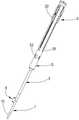
图1为实施例中穿刺扩张器的立体结构图;Fig. 1 is the three-dimensional structure diagram of the puncture dilator in the embodiment;
图2为实施例中穿刺扩张器的爆炸图;Figure 2 is an exploded view of the puncture dilator in the embodiment;
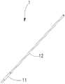
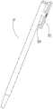
图3为实施例中一级管体的立体结构图;Fig. 3 is the three-dimensional structure diagram of the primary pipe body in the embodiment;
图4为实施例中二级管体的剖视图;4 is a cross-sectional view of a secondary tube body in an embodiment;
图5为实施例中三级管体的立体结构图;Fig. 5 is the three-dimensional structure diagram of the three-stage pipe body in the embodiment;
图6为实施例中四级管体的立体结构图;Fig. 6 is the three-dimensional structure diagram of the four-stage pipe body in the embodiment;
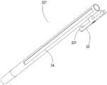
图7为实施例中五级管体的立体结构图;Fig. 7 is the three-dimensional structure diagram of the five-stage pipe body in the embodiment;
图8为实施例中六级管体的立体结构图;Fig. 8 is the three-dimensional structure diagram of the six-stage pipe body in the embodiment;
图9为实施例中管体保护壳的立体结构图。FIG. 9 is a three-dimensional structural view of the protective casing of the tube body in the embodiment.
附图标记说明Description of reference numerals
1-一级管体;11-头部;12-一级管身;2-二级管体;21-锥形孔;3-管体扩张件;31-三级管体;32-扩张管体;321-四级管体;322-五级管体;323-六级管体;33-推送手柄;331-过渡斜边;34-第一推送槽;4-第一角度;5-管体保护壳;51-第二推送槽;52-固定槽。1-first-stage tube body; 11-head; 12-first-stage tube body; 2-second-stage tube body; 21-conical hole; 3-tube body expansion piece; 31-third-stage tube body; 32-expansion tube body; 321-four-stage pipe body; 322-five-stage pipe body; 323-six-stage pipe body; 33-push handle; 331-transition hypotenuse; 34-first push groove; 4-first angle; 5-pipe body protection shell; 51-second push groove; 52-fixed groove.
具体实施方式Detailed ways
以下将以图式揭露本发明的多个实施方式,为明确说明起见,许多实务上的细节将在以下叙述中一并说明。然而,应了解到,这些实务上的细节不应用以限制本发明。也就是说,在本发明的部分实施方式中,这些实务上的细节是非必要的。此外,为简化图式起见,一些习知惯用的结构与组件在图式中将以简单的示意的方式绘示之。Various embodiments of the present invention will be disclosed in the drawings below, and for the sake of clarity, many practical details will be described together in the following description. It should be understood, however, that these practical details should not be used to limit the invention. That is, in some embodiments of the invention, these practical details are unnecessary. In addition, for the purpose of simplifying the drawings, some well-known structures and components will be shown in a simple schematic manner in the drawings.
另外,在本发明中如涉及“第一”、“第二”等的描述仅用于描述目的,并非特别指称次序或顺位的意思,亦非用以限定本发明,其仅仅是为了区别以相同技术用语描述的组件或操作而已,而不能理解为指示或暗示其相对重要性或者隐含指明所指示的技术特征的数量。由此,限定有“第一”、“第二”的特征可以明示或者隐含地包括至少一个该特征。另外,各个实施例之间的技术方案可以相互结合,但是必须是以本领域普通技术人员能够实现为基础,当技术方案的结合出现相互矛盾或无法实现时应当认为这种技术方案的结合不存在,也不在本发明要求的保护范围之内。In addition, descriptions such as “first”, “second”, etc. in the present invention are only for the purpose of description, and do not refer to the meaning of order or sequence, nor are they used to limit the present invention. The components or operations are described by the same technical terms, and should not be construed as indicating or implying their relative importance or implying the quantity of the indicated technical features. Thus, a feature delimited with "first", "second" may expressly or implicitly include at least one of that feature. In addition, the technical solutions between the various embodiments can be combined with each other, but must be based on the realization by those of ordinary skill in the art. When the combination of technical solutions is contradictory or cannot be realized, it should be considered that the combination of such technical solutions does not exist. , is not within the scope of protection required by the present invention.
需要说明的是,在本发明中,“近端”和“远端”是从使用该医疗器械的医生角度来看相对于彼此的元件或动作的相对方位、相对位置、方向,尽管“近端”和“远端”并非是限制性的,但是“近端”通常指该医疗器械在正常操作过程中靠近医生的一端,而“远端”通常是指首先进入患者体内的一端。It should be noted that, in the present invention, "proximal end" and "distal end" are relative orientations, relative positions, and directions of elements or actions relative to each other from the perspective of the doctor using the medical device, although "proximal end" " and "distal" are not limiting, but "proximal" generally refers to the end of the medical device that is closest to the physician during normal operation, and "distal" generally refers to the end that first enters the patient.
如图1-图2所示,图1为实施例中穿刺扩张器的立体结构图;图2为实施例中穿刺扩张器的爆炸图。本发明的穿刺扩张器包括一级管体1、二级管体2及管体扩张件3,二级管体2位于一级管体1的近端,管体扩张件3位于二级管体2的近端,并且管体扩张件3活动设置于二级管体2内;二级管体2由弹性材质制成,其中,管体扩张件3通过在二级管体2内运动,改变二级管体2的外径大小,最终实现二极管体的变径。As shown in Figures 1-2, Figure 1 is a three-dimensional structural view of the puncture dilator in the embodiment; Figure 2 is an exploded view of the puncture dilator in the embodiment. The puncture dilator of the present invention comprises a
具体的,二级管体2的外径大于一级管体1的外径。Specifically, the outer diameter of the
穿刺扩张器使用时,先将一级管体1插入相应部位,再持续推入穿刺扩张器,使得二级管体2达到一级管体1位置,作进一步扩张,随后推动管体扩张件3,由于二级管体2为弹性材质,当管体扩张件3与二级管体2结合后,二级管体2发生形变,即二级管体2的外径被撑大,最终相应的部位被扩张到合适的程度,可进行下一步的处理。When using the puncture dilator, first insert the
再一并参照图3所示,图3为实施例中一级管体1的立体结构图。一级管体1包括头部11及一级管身12,头部11设置于一级管身12的远端,二级管体2套设于一级管身12,且二级管体2的远端与头部11的近端连接;管体扩张件3活动套设于一级管身12。具体应用时,头部11的外径大于一级管身12的外径,故头部11与一级管身12连接处存在台阶,二级管体2则位于该台阶处。优选地,为了使得头部11与二级管体2过渡顺畅及平缓,减少对相应部位的损伤,二级管体2与头部11连接处成第一角度4设置,具体的,第一角度4为钝角或者平角。Referring again to FIG. 3 , FIG. 3 is a three-dimensional structural view of the
再一并参照图4所示,图4为实施例中二级管体2的剖视图。优选地,二级管体2的近端设有锥形孔21,通过锥形孔21的设置,便于管体扩张件3运动至二级管体2内,此外,锥形孔21的设置还对管体扩张件3起到导引作用。Referring again to FIG. 4 , FIG. 4 is a cross-sectional view of the
再一并参照图5-图8所示,图5为实施例中三级管体31的立体结构图;图6为实施例中四级管体321的立体结构图;图7为实施例中五级管体322的立体结构图;图8为实施例中六级管体34的立体结构图。请复阅图2,管体扩张件3包括三级管体31,三级管体31活动套设于一级管身12,且三级管体31的远端抵接锥形孔21。具体应用时,三级管体31的外径大于锥形孔21的孔径,三级管体31插入到二级管体2内,将二级管体2由内向外撑大,使得二级管体2外径变大。Referring again to FIGS. 5-8 , FIG. 5 is a three-dimensional structure diagram of the three-
优选地,管体扩张件3还包括扩张管体32,扩张管体32活动套设于三级管体31,当三级管体31插入二级管体2后,再将扩张管体32也插入二级管体2内,在三级管体31扩张后,再插入扩张管体32进一步扩张。Preferably, the tube
具体应用时,扩张管体32包括四级管体321,四级管体321活动套设于三级管体31,四级管体321的外径大于三级管体31,当三级管体31插入二级管体2后,再将四级管体321也插入二级管体2内,此时,四级管体321位于三级管体31外壁面与二级管体2内壁面之间,进一步将二级管体2外径撑大,实现扩张。In a specific application, the
进一步地,扩张管体32还可以包括五级管体322,五级管体322活动套设于四级管体321,五级管体322的外径大于四级管体322,当四级管体321插入到二级管体2后,再将五级管体322也插入到二级管体2内,此时,五级管体322位于四级管体321外壁面与二级管体2内壁面之间,进一步将二级管体2外径撑大,实现扩张。Further, the
再进一步地,扩张管体32还可以包括六级管体323,六级管体323活动套设于五级管体322,六级管体323的外径大于五级管体323,当五级管体322插入到二级管体2后,再将六级管体323也插入到二级管体2内,此时,六级管体323位于五级管体322外壁面与二级管体2内壁面之间,进一步将二级管体2外径撑大,实现扩张。Still further, the
需要说明的是,本实施例中将以扩张管体32包括四级管体321、五级管体322及六级管体323进行举例说明,四级管体321、五级管体322及六级管体323的外径尺寸依序增加。具体的,四级管体321、五级管体322及六级管体323的外径尺寸逐级递增1-2mm。当然,在二级管体2的弹性承受范围内,管体扩张件3所包括的管体的数量将不作限定,也就是说,管体扩张件3还可以包括七级管体、八级管体等。It should be noted that, in this embodiment, the
优选地,三级管体31、四级管体321、五级管体322及六级管体323的近端均设有推送手柄33。具体应用时,推送手柄33的整体形状类似于“E”字型,其中部与相应的管体进行连接,两端悬空,通过推送手柄33的设置,方便使用者推动相应的管体到二级管体2内。具体的,为了提高使用时的辨别度,每个推送手柄33的外壁面刻有尺寸标记,例如三级管体31刻有12FR,四级管体321刻有14FR,五级管体322刻有16FR,六级管体323刻有18FR;为了不对相应的部位造成损伤,应逐级递增地进行扩张,使用者可根据尺寸标记推动对应的管体,有效降低工作失误的现象发生。Preferably, the proximal ends of the third-
优选地,推送手柄33的两端部分别设有过渡斜边331,其中一端的过渡斜边331是方便不使用时对相应管体进行固定;其另一端则是方便使用过程中对相应的管体进行固定。Preferably, the two ends of the push handle 33 are respectively provided with transition bevels 331, wherein the
优选地,由于三级管体31、四级管体321、五级管体322及六级管体323是一层包裹一层的结构,故四级管体321、五级管体322及六级管体323上均设有第一推送槽34,第一推送槽34与一级管身12长度方向平行设置,用于为相应管体上的推送手柄33提供运动空间。具体应用时,六级管体323处于最外层,需要为三级管体31、四级管体321及五级管体322的推送手柄33提供运动空间,故其设有三个第一推送槽34;五级管体322处于倒数第二层,需要为三级管体31及四级管体321的推送手柄33提供运动空间,故其设有两个第一推送槽34;四级管体321处于倒数第三层,需要为三级管体31的推送手柄33提供运动空间,故其设有一个第一推送槽34;三级管体31处于最内层,故无需设有第一推送槽34。Preferably, since the third-
再一并参照图9所示,图9为实施例中管体保护壳5的立体结构图。优选地,穿刺扩张器还包括管体保护壳5,管体保护壳5位于二级管体2的近端,且管体保护壳5套设于一级管身12,三级管体31、四级管体321、五级管体322及六级管体323均活动设置于管体保护壳5内;通过管体保护壳5的设置,可对三级管体31、四级管体321、五级管体322及六级管体323进行保护,防止受外物冲击或撞击造成损坏,同时,增强管体使用过程中的稳定性。具体应用时,管体保护壳5设有第二推送槽51,第二推送槽51的设置方向与第一推送槽34的相同,同样是为了给推送手柄33提供运动空间,便于推送手柄33的运动。具体的,第二推送槽51的数量与推送手柄33的数量相对应,即第二推送槽51的数量为四个。为了提高穿刺扩张器的使用体验感以及其整体美观性,可将四个第二推送槽51等距环绕设置于管体保护壳5,第一推送槽34及推送手柄33的位置也相对应设置。Referring again to FIG. 9 , FIG. 9 is a three-dimensional structural view of the tube
优选地,管体保护壳5还设有固定槽52,固定槽52位于管体保护壳5的远端。具体应用时,固定槽52的数量与推送手柄33的数量相对应,即固定槽52的数量为四个,且每一固定槽52的位置与每一个推送手柄33的位置相对应,两者处于同一水平线上,通过固定槽52的设置,可对正在使用中的相应管体进行位置固定,替代人工手动固定,增强穿刺扩张器的使用便捷性。Preferably, the tube
穿刺扩张器使用时,先将一级管体1插入相应部位,然后逐渐推入使得二级管体2处于一级管体1的位置,此时,相应部位得到扩张,通过推送手柄33将三级管体31朝靠近二级管体2的方向推动,到达一定位置后,在推送手柄33一端的过渡斜边331的作用下,推送手柄33的一端滑出第二推送槽51,随着持续推动推送手柄33,推送手柄33的一端最终扣合于固定槽52内进行固定,三级管体31也与二级管体2结合,二级管体2被撑大一定的程度,进而使得相应的部位再次被扩张,如此类推,将四级管体321、五级管体322及六级管体323推出,二级管体2不断被撑大,最终使得相应的部位被扩张到所需的程度。使用完后,分别将三级管体31、四级管体321、五级管体322及六级管体323从固定槽52内抠出并推动至初始位置,同时,推送手柄33的另一端在过渡斜边331的作用下更方便的扣合于管体保护壳5端部。When using the puncture dilator, first insert the
综上,通过一级管体、二级管体及管体扩张件的配合使用,一级管体先进行初步扩张,再经过二级管体进一步扩张,管体扩张件与二级管体结合,由于二极管体的弹性作用使其发生形变,进而增大二级管体的外径,增大扩张程度,通过该方式进行的扩张,无需进行多次的穿刺,减少穿刺步骤和时间,方便操作,并且还能大大降低过程中血液流失的风险。In summary, through the cooperative use of the primary tube body, the secondary tube body and the tube body expansion piece, the primary tube body is initially expanded first, and then further expanded through the secondary tube body, and the tube body expansion piece is combined with the secondary tube body. , Due to the elastic effect of the diode body, it deforms, thereby increasing the outer diameter of the diode body and increasing the degree of expansion. The expansion performed in this way does not need to perform multiple punctures, reduces the puncture steps and time, and facilitates operation. , and also greatly reduces the risk of blood loss during the process.
上所述仅为本发明的实施方式而已,并不用于限制本发明。对于本领域技术人员来说,本发明可以有各种更改和变化。凡在本发明的精神和原理的内所作的任何修改、等同替换、改进等,均应包括在本发明的权利要求范围之内。The above description is merely an embodiment of the present invention, and is not intended to limit the present invention. Various modifications and variations of the present invention are possible for those skilled in the art. Any modification, equivalent replacement, improvement, etc. made within the spirit and principle of the present invention shall be included within the scope of the claims of the present invention.
Claims (10)
Translated fromChinesePriority Applications (1)
| Application Number | Priority Date | Filing Date | Title |
|---|---|---|---|
| CN202010469886.XACN111658084B (en) | 2020-05-28 | 2020-05-28 | Puncture dilator |
Applications Claiming Priority (1)
| Application Number | Priority Date | Filing Date | Title |
|---|---|---|---|
| CN202010469886.XACN111658084B (en) | 2020-05-28 | 2020-05-28 | Puncture dilator |
Publications (2)
| Publication Number | Publication Date |
|---|---|
| CN111658084Atrue CN111658084A (en) | 2020-09-15 |
| CN111658084B CN111658084B (en) | 2022-04-15 |
Family
ID=72385010
Family Applications (1)
| Application Number | Title | Priority Date | Filing Date |
|---|---|---|---|
| CN202010469886.XAExpired - Fee RelatedCN111658084B (en) | 2020-05-28 | 2020-05-28 | Puncture dilator |
Country Status (1)
| Country | Link |
|---|---|
| CN (1) | CN111658084B (en) |
Citations (7)
| Publication number | Priority date | Publication date | Assignee | Title |
|---|---|---|---|---|
| US5246424A (en)* | 1992-03-13 | 1993-09-21 | Wilk Peter J | Device and method for use in obtaining access to an internal body organ |
| CN201030137Y (en)* | 2007-01-18 | 2008-03-05 | 东莞科威医疗器械有限公司 | Double-step flexible tip expander |
| CN202342662U (en)* | 2011-10-20 | 2012-07-25 | 杭州康基医疗器械有限公司 | Abdominal wall dilator |
| CN102671287A (en)* | 2012-05-07 | 2012-09-19 | 先健科技(深圳)有限公司 | Puncture dilator |
| CN204379379U (en)* | 2014-12-31 | 2015-06-10 | 山东省立医院 | A kind of puncture convergent divergent channel of multilayer nest |
| CN209060323U (en)* | 2018-07-12 | 2019-07-05 | 深圳大学 | urethral dilation kit |
| CN110720969A (en)* | 2019-10-17 | 2020-01-24 | 深圳泰睿仕医疗科技有限公司 | Disposable minimally invasive dilation drainage kit |
- 2020
- 2020-05-28CNCN202010469886.XApatent/CN111658084B/ennot_activeExpired - Fee Related
Patent Citations (7)
| Publication number | Priority date | Publication date | Assignee | Title |
|---|---|---|---|---|
| US5246424A (en)* | 1992-03-13 | 1993-09-21 | Wilk Peter J | Device and method for use in obtaining access to an internal body organ |
| CN201030137Y (en)* | 2007-01-18 | 2008-03-05 | 东莞科威医疗器械有限公司 | Double-step flexible tip expander |
| CN202342662U (en)* | 2011-10-20 | 2012-07-25 | 杭州康基医疗器械有限公司 | Abdominal wall dilator |
| CN102671287A (en)* | 2012-05-07 | 2012-09-19 | 先健科技(深圳)有限公司 | Puncture dilator |
| CN204379379U (en)* | 2014-12-31 | 2015-06-10 | 山东省立医院 | A kind of puncture convergent divergent channel of multilayer nest |
| CN209060323U (en)* | 2018-07-12 | 2019-07-05 | 深圳大学 | urethral dilation kit |
| CN110720969A (en)* | 2019-10-17 | 2020-01-24 | 深圳泰睿仕医疗科技有限公司 | Disposable minimally invasive dilation drainage kit |
Also Published As
| Publication number | Publication date |
|---|---|
| CN111658084B (en) | 2022-04-15 |
Similar Documents
| Publication | Publication Date | Title |
|---|---|---|
| JP4986176B2 (en) | Insertion aid for percutaneous tracheostomy | |
| EP3673948B1 (en) | Dilatable balloon catheter | |
| JP6772386B2 (en) | Catheter tube | |
| WO2017202042A1 (en) | Balloon catheter provided with flexible connecting part between tip and balloon | |
| GB2146902A (en) | Preformed catheter | |
| CN107280718A (en) | A kind of folding exhibition variation rigidity apparatus arm and its application process performed the operation for natural cavity | |
| EP3354244A1 (en) | Deformable tampon | |
| CN204484874U (en) | A kind of negative pressure suction head | |
| CN111658084B (en) | Puncture dilator | |
| EP2149385A1 (en) | Balloon catheter and sheath fabrication method | |
| CN201365911Y (en) | Incision expander used for laparoscopic surgery | |
| CN118649339A (en) | A balloon dilatation catheter | |
| CN209153916U (en) | An obstetric cervical extension rod | |
| BR112015009452B1 (en) | Flexible and extensible tubular guide and process for producing a guide | |
| CN110652279A (en) | A laparoscope with telescopic function | |
| CN217659802U (en) | Bent sheath tube and guide sheath | |
| BRMU8600250Y1 (en) | CONSTRUCTIVE ARRANGEMENT APPLIED IN BALLOON CATHETER | |
| CN210494016U (en) | Visual hard mirror for children | |
| CN113631106B (en) | Cannula delivery catheter and surgical method | |
| CN212547090U (en) | Disposable calculus plugging device | |
| CN210055971U (en) | Biliary tract dilator under laparoscope | |
| CN211132648U (en) | catheter dilator | |
| CN219354884U (en) | Catheter device | |
| CN204995521U (en) | Wicresoft's convergent divergent channel and wicresoft's expansion drainage external member | |
| CN222693363U (en) | A ureteroscope guide sheath kit |
Legal Events
| Date | Code | Title | Description |
|---|---|---|---|
| PB01 | Publication | ||
| PB01 | Publication | ||
| SE01 | Entry into force of request for substantive examination | ||
| SE01 | Entry into force of request for substantive examination | ||
| GR01 | Patent grant | ||
| GR01 | Patent grant | ||
| CF01 | Termination of patent right due to non-payment of annual fee | ||
| CF01 | Termination of patent right due to non-payment of annual fee | Granted publication date:20220415 |