CN111657999A - Bracket arm power-assisted frame for relieving occupational injury of ultrasonic doctors - Google Patents
Bracket arm power-assisted frame for relieving occupational injury of ultrasonic doctorsDownload PDFInfo
- Publication number
- CN111657999A CN111657999ACN202010613178.9ACN202010613178ACN111657999ACN 111657999 ACN111657999 ACN 111657999ACN 202010613178 ACN202010613178 ACN 202010613178ACN 111657999 ACN111657999 ACN 111657999A
- Authority
- CN
- China
- Prior art keywords
- groove
- electromagnet
- rope
- motor
- support arm
- Prior art date
- Legal status (The legal status is an assumption and is not a legal conclusion. Google has not performed a legal analysis and makes no representation as to the accuracy of the status listed.)
- Granted
Links
Images


Classifications
- A—HUMAN NECESSITIES
- A61—MEDICAL OR VETERINARY SCIENCE; HYGIENE
- A61B—DIAGNOSIS; SURGERY; IDENTIFICATION
- A61B8/00—Diagnosis using ultrasonic, sonic or infrasonic waves
- A61B8/44—Constructional features of the ultrasonic, sonic or infrasonic diagnostic device
- A—HUMAN NECESSITIES
- A61—MEDICAL OR VETERINARY SCIENCE; HYGIENE
- A61B—DIAGNOSIS; SURGERY; IDENTIFICATION
- A61B90/00—Instruments, implements or accessories specially adapted for surgery or diagnosis and not covered by any of the groups A61B1/00 - A61B50/00, e.g. for luxation treatment or for protecting wound edges
- A61B90/60—Supports for surgeons, e.g. chairs or hand supports
- B—PERFORMING OPERATIONS; TRANSPORTING
- B65—CONVEYING; PACKING; STORING; HANDLING THIN OR FILAMENTARY MATERIAL
- B65H—HANDLING THIN OR FILAMENTARY MATERIAL, e.g. SHEETS, WEBS, CABLES
- B65H75/00—Storing webs, tapes, or filamentary material, e.g. on reels
- B65H75/02—Cores, formers, supports, or holders for coiled, wound, or folded material, e.g. reels, spindles, bobbins, cop tubes, cans, mandrels or chucks
- B65H75/34—Cores, formers, supports, or holders for coiled, wound, or folded material, e.g. reels, spindles, bobbins, cop tubes, cans, mandrels or chucks specially adapted or mounted for storing and repeatedly paying-out and re-storing lengths of material provided for particular purposes, e.g. anchored hoses, power cables
- B65H75/38—Cores, formers, supports, or holders for coiled, wound, or folded material, e.g. reels, spindles, bobbins, cop tubes, cans, mandrels or chucks specially adapted or mounted for storing and repeatedly paying-out and re-storing lengths of material provided for particular purposes, e.g. anchored hoses, power cables involving the use of a core or former internal to, and supporting, a stored package of material
- B65H75/44—Constructional details
- B—PERFORMING OPERATIONS; TRANSPORTING
- B65—CONVEYING; PACKING; STORING; HANDLING THIN OR FILAMENTARY MATERIAL
- B65H—HANDLING THIN OR FILAMENTARY MATERIAL, e.g. SHEETS, WEBS, CABLES
- B65H2701/00—Handled material; Storage means
- B65H2701/30—Handled filamentary material
- B65H2701/34—Handled filamentary material electric cords or electric power cables
Landscapes
- Health & Medical Sciences (AREA)
- Life Sciences & Earth Sciences (AREA)
- Surgery (AREA)
- Medical Informatics (AREA)
- Animal Behavior & Ethology (AREA)
- Veterinary Medicine (AREA)
- Nuclear Medicine, Radiotherapy & Molecular Imaging (AREA)
- Engineering & Computer Science (AREA)
- Biomedical Technology (AREA)
- Heart & Thoracic Surgery (AREA)
- Public Health (AREA)
- Molecular Biology (AREA)
- Pathology (AREA)
- General Health & Medical Sciences (AREA)
- Dentistry (AREA)
- Oral & Maxillofacial Surgery (AREA)
- Physics & Mathematics (AREA)
- Biophysics (AREA)
- Radiology & Medical Imaging (AREA)
- Ultra Sonic Daignosis Equipment (AREA)
Abstract
Translated fromChinese
Description
Translated fromChinese技术领域technical field
本发明涉及助力架领域,特别涉及一种缓解超声医生职业损害的托臂助力架。The invention relates to the field of booster frames, in particular to a support arm booster frame for relieving the occupational damage of ultrasound doctors.
背景技术Background technique
目前全国各级医院均已普及超声,随着超声技术的发展,应用范围也越来越广泛,超声检查量剧增,超声医生常处于高负荷工作状态。实施检查时超声医师的右侧手臂除了不断移动按压受检者,而且处于半悬空状态,因此操作者的右臂腕、肩、颈、腰等部位持续处于非生理性的体位和紧张状态。日积月累,超声医生包括很多年轻医生都容易发生颈肩部肌肉劳损,严重者会进而发展为肩周炎、腰椎间盘突出慢性疾病。At present, ultrasound has been popularized in hospitals at all levels across the country. With the development of ultrasound technology, the scope of application has become more and more extensive, and the volume of ultrasound examinations has increased sharply. Ultrasound doctors are often in a state of high workload. During the examination, the sonographer's right arm is not only constantly moving and pressing on the subject, but also in a semi-suspended state, so the operator's right arm, wrist, shoulder, neck, waist and other parts continue to be in a non-physiological position and a tense state. Over time, ultrasound doctors, including many young doctors, are prone to neck and shoulder muscle strain. In severe cases, they will develop into chronic diseases of frozen shoulder and lumbar disc herniation.
对于上述的问题,目前有相应的设备来解决该技术问题,具体的,是通过夹持在检查床上的固定装置,固定装置上连接有竖直支杆,竖直支杆的顶部固定有水平支杆,水平支杆上通过吊挂装置连接有手臂拖体,医生通过将手臂放在手臂托体上对受检者进行检查,这样就可以通过很大程度的减缓医生手臂的悬空状态。但是,目前的这个设备只能固定在同一个位置,不能灵活的进行调节,当医生要对受检者的劝说多个部位进行检查的时候,就需要不断的将还装置从检查床上取下然后再固定,否则就很难达到减缓医生手臂的悬空状态的效果,因此,该装置在使用的时候,虽然可以达到一定的减缓医生手臂的悬空状态的效果,但是在使用的时候,非常不方便。For the above problem, there are corresponding equipment to solve the technical problem. Specifically, the fixing device is clamped on the examination bed. The fixing device is connected with a vertical support rod, and the top of the vertical support rod is fixed with a horizontal support The arm drag body is connected to the horizontal support rod through a hanging device. The doctor checks the subject by placing the arm on the arm support body, so that the suspended state of the doctor's arm can be greatly reduced. However, the current device can only be fixed in the same position, and cannot be adjusted flexibly. When the doctor wants to examine multiple parts of the subject's persuasion, he needs to continuously remove the device from the examination bed and then If it is fixed again, it will be difficult to achieve the effect of slowing down the hanging state of the doctor's arm. Therefore, although the device can achieve a certain effect of slowing down the hanging state of the doctor's arm when in use, it is very inconvenient to use.
发明内容SUMMARY OF THE INVENTION
本发明的目的是克服上述现有技术中存在的问题,提供一种缓解超声医生职业损害的托臂助力架,将该托臂助力架夹持在检查床上,通过红外检测仪检测到超声医生当前检查的位置状态,并且根据当前检查的位置状态移动该托臂助力架的位置,使得在多个部位做检测的时候,无需不断的夹取托臂助力架,为检查节约了时间。The purpose of the present invention is to overcome the problems existing in the above-mentioned prior art, and to provide a support arm booster for alleviating the occupational damage of an ultrasound doctor. Check the position state, and move the position of the support arm booster according to the current check position state, so that when testing multiple parts, there is no need to constantly clamp the support arm booster, which saves time for inspection.
为此,本发明提供一种缓解超声医生职业损害的托臂助力架,包括:夹具,用于夹持在检查床上,且其夹持面上设有滚轮;第一红外探测仪,用于检测超声医生的手臂位置,其数量有两个,分别设置在竖直支杆上,竖直支杆固定在所述夹具上,两个所述第一红外探测仪在所述竖直支杆上的高度相同,且成开口向超声医生手臂方向的八字形分布;手臂托体,通过第一绳索连接在水平支杆上,所述水平支杆的一端固定在所述竖直支杆的顶部;固定块,其数量有两个,分别设置在所述夹具的左右两侧,每一个固定块的侧面均开设有第一凹槽,第一凹槽内设置有自动收线器,自动收线器与第二绳索的一端连接,第二绳索的另一端设置有固定扣,所述第二绳索的外表面包括若干个节,相邻两个节的外表面颜色不一致,所述第一凹槽内还设置有用于检测所述第二绳索外表面颜色的颜色传感器;中央处理器,分别与所述第一红外探测仪、自动收线器以及颜色传感器信号连接;电源装置,分别与所述中央处理器、第一红外探测仪、自动收线器以及颜色传感器电连接。To this end, the present invention provides a support arm booster for alleviating the occupational damage of an ultrasound doctor, including: a clamp, which is used for clamping on an examination bed, and the clamping surface is provided with a roller; a first infrared detector is used for detecting The arm positions of the ultrasound doctor, there are two in number, are respectively arranged on the vertical support rods, the vertical support rods are fixed on the fixture, and the two first infrared detectors are located on the vertical support rods. The height is the same, and is distributed in a figure-eight shape with the opening facing the direction of the ultrasound doctor's arm; the arm support body is connected to the horizontal support rod through the first rope, and one end of the horizontal support rod is fixed on the top of the vertical support rod; fixed There are two blocks, which are respectively arranged on the left and right sides of the fixture. The side of each fixing block is provided with a first groove, and an automatic wire take-up is arranged in the first groove. One end of the second rope is connected, and the other end of the second rope is provided with a fixing buckle. A color sensor for detecting the color of the outer surface of the second rope is provided; a central processing unit, which is respectively connected with the first infrared detector, the automatic wire take-up device and the color sensor; a power supply unit, which is respectively connected with the central processing unit , the first infrared detector, the automatic wire take-up device and the color sensor are electrically connected.
进一步,所述自动收线器包括:第一电机,固定在所述第一凹槽的其中一侧槽壁上;第一转轴,其一端与所述第一电机的输出轴通过键连接,其另一端通过第一轴承连接在所述第一凹槽的另一侧槽壁上;所述中央处理器与所述第一电机信号连接,所述电源装置与所述第一电机电连接;所述颜色传感器位于所述第一凹槽的槽口处。Further, the automatic wire take-up device includes: a first motor, which is fixed on one side wall of the first groove; a first rotating shaft, one end of which is connected with the output shaft of the first motor through a key, which is The other end is connected to the other side groove wall of the first groove through a first bearing; the central processing unit is signally connected to the first motor, and the power supply device is electrically connected to the first motor; The color sensor is located at the notch of the first groove.
进一步,所述夹具包括交叉设置的两个夹板,两个夹板在交汇处通过铰接件铰接,两个夹板的交汇处设置有扭力弹簧,所述竖直支杆固定在位于上方的夹板上,所述滚轮有偶数个且分别设置在两个所述夹板相对面上,上下两个所述滚轮的位置一一向对。Further, the clamp includes two cross-arranged splints, the two splints are hinged at the intersection through a hinge, a torsion spring is arranged at the intersection of the two splints, and the vertical support rod is fixed on the upper splint, so There are an even number of the rollers and they are respectively arranged on the opposite surfaces of the two splints, and the positions of the upper and lower rollers are opposite to each other.
更进一步,两个所述夹板相对的面上分别设置有一第一电磁铁,第一电磁铁与所述中央处理器信号连接,第一电磁铁与所述电源装置电连接。Furthermore, a first electromagnet is respectively disposed on the opposite surfaces of the two splints, the first electromagnet is signally connected to the central processing unit, and the first electromagnet is electrically connected to the power supply device.
更进一步,所述夹板上设置所述滚轮的位置开设有第二凹槽,第二凹槽的槽内设置有连接体,连接体的一端恒位于所述第二凹槽的内部,连接体的另一端位于所述第二凹槽的外部并且设置所述滚轮,所述第二凹槽的槽底固定有第二电磁铁,所述连接体与所述第二凹槽槽底相对的一面设置有第三电磁铁,所述第二电磁铁和所述第三电磁铁在通电后呈现出相同的磁极,所述第二电磁铁和所述第三电磁铁分别与所述中央处理器信号连接,所述第二电磁铁和所述第三电磁铁分别与所述电源装置电连接。Further, a second groove is provided at the position where the roller is arranged on the splint, a connecting body is arranged in the groove of the second groove, one end of the connecting body is always located inside the second groove, and the connecting body is The other end is located outside the second groove and is provided with the roller, the bottom of the second groove is fixed with a second electromagnet, and the side of the connecting body opposite to the bottom of the second groove is provided There is a third electromagnet, the second electromagnet and the third electromagnet show the same magnetic pole after being energized, and the second electromagnet and the third electromagnet are respectively connected with the central processing unit signal , the second electromagnet and the third electromagnet are respectively electrically connected with the power supply device.
进一步,所述水平支杆的下表面沿其长度方向开设有水平方向的滑槽,滑槽上滑动连接有滑块,滑块下面固定有连接板,连接板的下面与所述第一绳索连接。Further, the lower surface of the horizontal strut is provided with a horizontal chute along its length direction, a slider is slidably connected to the chute, a connecting plate is fixed under the slider, and the lower part of the connecting plate is connected with the first rope .
更进一步,还包括:第二红外探测仪,用于检测受检者的身体与所述连接板之间的距离,设置在所述连接板的下面;所述连接板下面开始有第三凹槽,第三凹槽内设置有第二转轴,第二转轴的一端与第二电机的输出轴通过键连接,第二电机固定在所述第三凹槽的其中一侧槽壁上,第二转轴的另一端通过第二轴承连接在所述第三凹槽的另一侧槽壁上,所述第二转轴的轴身上固定所述第一绳索;所述中央处理器分别与所述第二红外探测仪和所述第二电机信号连接,所述电源装置分别与所述第二红外探测仪和所述第二电机电连接。Further, it also includes: a second infrared detector for detecting the distance between the subject's body and the connecting plate, which is arranged below the connecting plate; a third groove starts from the bottom of the connecting plate , a second rotating shaft is arranged in the third groove, one end of the second rotating shaft is connected with the output shaft of the second motor by a key, the second motor is fixed on one side of the groove wall of the third groove, and the second rotating shaft is The other end is connected to the other side groove wall of the third groove through a second bearing, and the first rope is fixed on the shaft body of the second rotating shaft; the central processing unit is respectively connected with the second infrared The detector is signally connected to the second motor, and the power supply device is electrically connected to the second infrared detector and the second motor, respectively.
更进一步,所述第二红外探测仪的数量有两个,两个所述第二红外探测仪分别设置在所述连接板的左右两侧。Further, the number of the second infrared detectors is two, and the two second infrared detectors are respectively arranged on the left and right sides of the connecting plate.
进一步,所述手臂拖体包括:弧形板,用于支撑超声医生的手臂;挂环,其内边缘沿所述弧形板的外表面固定,其顶部与所述第一绳索固定连接。Further, the arm drag body includes: an arc-shaped plate for supporting the ultrasound doctor's arm; a hanging ring, the inner edge of which is fixed along the outer surface of the arc-shaped plate, and the top of which is fixedly connected with the first rope.
进一步,所述电源装置为锂电池。Further, the power supply device is a lithium battery.
本发明提供的一种缓解超声医生职业损害的托臂助力架,具有如下有益效果:The invention provides a support arm support for alleviating the occupational damage of ultrasound doctors, which has the following beneficial effects:
1、将该托臂助力架夹持在检查床上,通过红外检测仪检测到超声医生当前检查的位置状态,并且根据当前检查的位置状态移动该托臂助力架的位置,使得在多个部位做检测的时候,无需不断的夹取托臂助力架,为检查节约了时间;1. Clamp the support arm booster on the examination bed, detect the position state of the ultrasound doctor currently inspected by the infrared detector, and move the position of the support arm booster according to the current inspection position state, so that the ultrasound can be performed in multiple parts. During inspection, there is no need to constantly clamp the support arm support frame, which saves time for inspection;
2、将该托臂助力架夹持在检查床上,能够根据受检者体型调节手臂拖体距离受检者之间的距离,使得超声医生在做检查的时候,可以有效的缓解手臂的悬空状态所带来的不适;2. The arm support frame is clamped on the examination bed, and the distance between the arm drag body and the examinee can be adjusted according to the body shape of the examinee, so that the ultrasound doctor can effectively relieve the suspended state of the arm during the examination. the discomfort caused;
3、通过在夹板内部设置滚轮,使得夹板的移动更加便捷,同时,通过电磁的作用使得夹板在检查床上夹持的更加牢固,同时周围没有视觉的干扰,在使用的时候也非常的方便。3. By setting the roller inside the splint, the movement of the splint is more convenient, and at the same time, the splint is more firmly clamped on the examination bed through the action of electromagnetism. At the same time, there is no visual interference around, and it is also very convenient to use.
附图说明Description of drawings
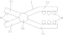
图1为本发明的整体结构示意图;Fig. 1 is the overall structure schematic diagram of the present invention;
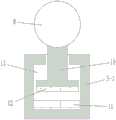
图2为竖直支杆的连接结构示意图;Fig. 2 is the connection structure schematic diagram of vertical strut;
图3为夹具的连接结构示意图;3 is a schematic diagram of the connection structure of the clamp;
图4为夹板的连接结构纵向剖视示意图;4 is a schematic longitudinal cross-sectional view of the connection structure of the splint;
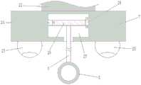
图5为夹具两侧的连接结构纵向剖视示意图;5 is a schematic longitudinal cross-sectional view of the connection structure on both sides of the clamp;
图6为水平支杆的连接结构纵向剖视示意图;6 is a schematic longitudinal cross-sectional view of the connection structure of the horizontal strut;
图7为连接板的连接结构纵向剖视示意图;7 is a schematic longitudinal cross-sectional view of a connecting structure of a connecting plate;
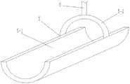
图8为手臂托体的连接结构透视示意图。FIG. 8 is a perspective schematic diagram of the connection structure of the arm support body.
附图标记说明:Description of reference numbers:
1、水平支杆;2、竖直支杆;3、夹具;3-1、夹板;3-2、扭力弹簧;4、第一红外探测仪;5、手臂托体;5-1、弧形板;5-2、挂环;6、第一绳索;7、连接板;8、滚轮;9、第一电磁铁;10、连接体;11、第二电磁铁;12、第三电磁铁;13、第二凹槽;14、固定块;15、第一电机;16、颜色传感器;17、第二绳索;18、第一转轴;19、第一凹槽;20、第一轴承;21、固定扣;22、滑块;23、滑槽;24、第二电机;25、第二红外探测仪;26、第二转轴;27、第三凹槽;28、第二轴承。1. Horizontal support rod; 2. Vertical support rod; 3. Clamp; 3-1, splint; 3-2, torsion spring; 4, first infrared detector; 5, arm support body; 5-1, arc plate; 5-2, hanging ring; 6, first rope; 7, connecting plate; 8, roller; 9, first electromagnet; 10, connecting body; 11, second electromagnet; 12, third electromagnet; 13, the second groove; 14, the fixed block; 15, the first motor; 16, the color sensor; 17, the second rope; 18, the first shaft; 19, the first groove; 20, the first bearing; 21, Fixed buckle; 22, slider; 23, chute; 24, second motor; 25, second infrared detector; 26, second shaft; 27, third groove; 28, second bearing.
具体实施方式Detailed ways
下面结合附图,对本发明的一个具体实施方式进行详细描述,但应当理解本发明的保护范围并不受具体实施方式的限制。A specific embodiment of the present invention will be described in detail below with reference to the accompanying drawings, but it should be understood that the protection scope of the present invention is not limited by the specific embodiment.
在本申请文件中,未经明确的部件型号以及结构,均为本领域技术人员所公知的现有技术,本领域技术人员均可根据实际情况的需要进行设定,在本申请文件的实施例中不做具体的限定。In this application document, the component models and structures that are not specified are the prior art known to those skilled in the art, and those skilled in the art can set it according to the needs of the actual situation. No specific restrictions are made.
具体的,如图1-8所示,本发明实施例提供了一种缓解超声医生职业损害的托臂助力架,包括:夹具3、第一红外探测仪4、手臂托体5、固定块14、中央处理器以及电源装置。其中,夹具3用于夹持在检查床上,且其夹持面上设有滚轮8,将滚轮8的方向设置为沿床边滚动,这样就可以使得滚轮8不会使得夹具3脱离检查床,并且始终在检查床的边缘线上进行运动。第一红外探测仪4用于检测超声医生的手臂位置,其数量有两个,分别设置在竖直支杆2上,竖直支杆2固定在所述夹具3上,两个所述第一红外探测仪4在所述竖直支杆2上的高度相同,且成开口向超声医生手臂方向的八字形分布。手臂托体5通过第一绳索6连接在水平支杆1上,所述水平支杆1的一端固定在所述竖直支杆2的顶部。固定块14的数量有两个,分别设置在所述夹具3的左右两侧,每一个固定块14的侧面均开设有第一凹槽19,第一凹槽19内设置有自动收线器,自动收线器与第二绳索17的一端连接,第二绳索17的另一端设置有固定扣21,所述第二绳索17的外表面包括若干个节,相邻两个节的外表面颜色不一致,所述第一凹槽19内还设置有用于检测所述第二绳索17外表面颜色的颜色传感器16。中央处理器分别与所述第一红外探测仪4、自动收线器以及颜色传感器16信号连接。电源装置分别与所述中央处理器、第一红外探测仪4、自动收线器以及颜色传感器16电连接。Specifically, as shown in FIGS. 1-8 , an embodiment of the present invention provides a support arm support frame for alleviating the occupational damage of an ultrasound doctor, including: a
上述技术方案的工作原理是:将夹具3夹持在检查床上,由于其夹持部分设置有滚轮8,因此,夹具3可以在检查床上进行滑动,将滚轮8的方向设置为沿床边滚动,这样就可以使得滚轮8不会使得夹具3脱离检查床,并且始终在检查床的边缘线上进行运动,具体的,夹具3沿着检查床的床边进行滑动,在超声医生对受检者进行检查的时候,将手臂放置在手臂托体5上,这样由于第一绳索6对于手臂托体5有一个向上的力的作用,就不会使得超声医生的手臂始终处于悬空的状态,这样就可以有效的减小超声医生在对受检者进行检查时候的手臂疲劳。同时,在超声医生对受检者身体的各个部分进行检查的时候,只需要放置在手臂托体5上对应的手部拿着超声探头,在手臂进行移动的时候,中央处理器实时的接收两个第一红外探测仪4所检测的数据,当其中一个第一红外探测仪4检测到数据的时候,说明超声医生的手臂向该第一红外探测仪4所在的方向移动,中央处理器控制该检测到数据的第一红外探测仪4位置方向同一层的自动收线器进行收线,使得夹具3向该方向滑动,直至两个第一红外探测仪4均没有检测到数据,说明超声医生的手臂没有发生位置的移动,中央处理器使得自动收线器停止工作,此时,夹具3保持不变,这样就可以使得在超声医生进行不同部位的检测的时候,不用反复的调节夹具3的位置,同时还可以使得在检测的时候,减少手臂的长时间悬空的状态,缓解肌肉疲劳。The working principle of the above technical solution is: the
在中央处理器控制两侧的自动收线器进行工作的时候,两侧的自动收线器始终处于相反的工作状态,当中央处理器都没有接收到两个第一红外探测仪4所检测到的信号的时候,此时,中央处理器始终接收颜色传感器16所检测的数据,当颜色传感器16检测到颜色发生变动的时候,此时,中央处理器改变自动收线器的工作状态是指停止工作,反之亦然。When the central processing unit controls the automatic wire take-up on both sides to work, the automatic wire take-up on both sides is always in the opposite working state, when the central processing unit does not receive the detection of the two first
在本实施例中,所述自动收线器包括:第一电机15和第一转轴18。其中,第一电机15固定在所述第一凹槽19的其中一侧槽壁上。第一转轴18的一端与所述第一电机15的输出轴通过键连接,其另一端通过第一轴承20连接在所述第一凹槽19的另一侧槽壁上。所述中央处理器与所述第一电机15信号连接,所述电源装置与所述第一电机15电连接。所述颜色传感器16位于所述第一凹槽19的槽口处。第二绳索17的一端固定在第一转轴18上。In this embodiment, the automatic wire take-up device includes: a
在控制自动收线器进行收线的时候,中央处理器使得第一电机15的输出轴进行转动,转动的方向根据夹具3要运动进行设定,在第一电机15的输出轴转动的时候,第一转轴18进行转动,使得第二绳索17进行收放,这样就可以使得夹具3被施加向左或者向右的力,这样就可以使得夹具3进行左右的运动。When controlling the automatic wire take-up to take up the wire, the central processing unit makes the output shaft of the
在本实施例中,所述夹具3包括交叉设置的两个夹板3-1,两个夹板3-1在交汇处通过铰接件铰接,两个夹板3-1的交汇处设置有扭力弹簧3-2,所述竖直支杆2固定在位于上方的夹板3-1上,所述滚轮8有偶数个且分别设置在两个所述夹板3-1相对面上,上下两个所述滚轮8的位置一一向对。In this embodiment, the
在使用的时候,将夹具3的上下两个夹板3-1夹持的检查床上,由于两个夹板3-1相对面上有滚轮8,因此,使得夹具3可以沿着检查穿的边缘进行滚动,同时,还有夹持的作用。扭力弹簧3-2的作用是使得夹具3夹持的更加牢固。When in use, on the inspection bed clamped by the upper and lower clamping plates 3-1 of the
同时,在本实施例中,两个所述夹板3-1相对的面上分别设置有一第一电磁铁9,第一电磁铁9与所述中央处理器信号连接,第一电磁铁9与所述电源装置电连接。Meanwhile, in this embodiment, a
在通电后,两个第一电磁铁9产生相同的磁极,这样就可以使得两个第一电磁铁9之间产生斥力,这样就可以使得夹板3-1夹持的更加牢固,使得夹具3的夹持效果更加的良好。After the power is turned on, the two
同时,在本实施例中,所述夹板3-1上设置所述滚轮8的位置开设有第二凹槽13,第二凹槽13的槽内设置有连接体10,连接体10的一端恒位于所述第二凹槽13的内部,连接体10的另一端位于所述第二凹槽13的外部并且设置所述滚轮8,所述第二凹槽13的槽底固定有第二电磁铁11,所述连接体10与所述第二凹槽13槽底相对的一面设置有第三电磁铁12,所述第二电磁铁11和所述第三电磁铁12在通电后呈现出相同的磁极,所述第二电磁铁11和所述第三电磁铁12分别与所述中央处理器信号连接,所述第二电磁铁11和所述第三电磁铁12分别与所述电源装置电连接。At the same time, in this embodiment, a
在通电后,第三电磁铁12与第二电磁铁11产生相同的磁极,此时,第三电磁铁12与第二电磁铁11之间产生斥力,因此,使得连接体10向第二凹槽13的方向运动,这样就会使得上下的滚轮8与检查床之间的接触力更大,使得夹持的更加牢固,同时,由于是滚轮8的设计,也不会使得夹具3在进行位置的移动的时候不方便。After the power is turned on, the
在本实施例中,所述水平支杆1的下表面沿其长度方向开设有水平方向的滑槽23,滑槽23上滑动连接有滑块22,滑块22下面固定有连接板7,连接板7的下面与所述第一绳索6连接。In this embodiment, the lower surface of the horizontal strut 1 is provided with a
在手臂托体5在水平支杆1的长度方向上进行移动的时候,连接杆7也会随之移动,此时,通过滑块22和滑槽23的配合就可以使得连接杆7进行移动,这样就可以配合手臂托体5进行移动。When the
同时,在本实施例中,还包括:第二红外探测仪25以及第三凹槽27。其中,第二红外探测仪25用于检测受检者的身体与所述连接板7之间的距离,设置在所述连接板7的下面。所述连接板7下面开始有第三凹槽27,第三凹槽27内设置有第二转轴26,第二转轴26的一端与第二电机24的输出轴通过键连接,第二电机24固定在所述第三凹槽27的其中一侧槽壁上,第二转轴26的另一端通过第二轴承28连接在所述第三凹槽27的另一侧槽壁上,所述第二转轴26的轴身上固定所述第一绳索6。所述中央处理器分别与所述第二红外探测仪25和所述第二电机24信号连接,所述电源装置分别与所述第二红外探测仪25和所述第二电机24电连接。Meanwhile, in this embodiment, it also includes: a second
上述技术方案中,中央处理器接收第二红外探测仪25所检测到的距离,得到连接块7与受检者身体之间的距离,并根据该距离控制第二电机24的旋转方向和旋转角度,并使得第二电机24进行转动,第二电机24使得第二转轴26转动,从而使得第一绳索6的下端上下运动,将第一绳索6下端的手臂托体5调节到合适的高度,这样就可以根据受检者的体型胖瘦进调节,使得超声医生的手臂对于任何受检者的体型都不会有悬空的状态。In the above technical solution, the central processing unit receives the distance detected by the second
同时,在本实施例中,所述第二红外探测仪25的数量有两个,两个所述第二红外探测仪25分别设置在所述连接板7的左右两侧。中央处理器将两个第二红外探测仪25的数据进行接收之后,得到两个数据的平均值,在根据该平均值控制第二电机24的旋转方向和旋转角度。Meanwhile, in this embodiment, the number of the second
在本实施例中,所述手臂拖体5包括:弧形板5-1和挂环5-2。其中,弧形板5-1用于支撑超声医生的手臂。挂环5-2的内边缘沿所述弧形板5-1的外表面固定,其顶部与所述第一绳索6固定连接。In this embodiment, the
在使用的时候,超声医生将手臂放置在弧形板5-1的弧形内,这样手臂在弧形的作用下较为舒适,挂环5-2可以对超声医生的手臂进行一定的限位,同时,在连接第一绳索6的时候非常的方便。When in use, the ultrasound doctor places the arm in the arc of the arc plate 5-1, so that the arm is more comfortable under the action of the arc. The hanging ring 5-2 can limit the ultrasound doctor's arm to a certain extent. At the same time, it is very convenient when connecting the
在本实施例中,所述电源装置为锂电池。这样可以进行反复的多次充电,提示电源装置的寿命和使用率。In this embodiment, the power supply device is a lithium battery. In this way, repeated charging can be carried out, indicating the life and usage rate of the power supply unit.
以上公开的仅为本发明的几个具体实施例,但是,本发明实施例并非局限于此,任何本领域的技术人员能思之的变化都应落入本发明的保护范围。The above disclosures are only a few specific embodiments of the present invention, however, the embodiments of the present invention are not limited thereto, and any changes that can be conceived by those skilled in the art should fall within the protection scope of the present invention.
Claims (10)
Translated fromChinesePriority Applications (1)
| Application Number | Priority Date | Filing Date | Title |
|---|---|---|---|
| CN202010613178.9ACN111657999B (en) | 2020-06-30 | 2020-06-30 | A support arm for alleviating occupational damage to ultrasound doctors |
Applications Claiming Priority (1)
| Application Number | Priority Date | Filing Date | Title |
|---|---|---|---|
| CN202010613178.9ACN111657999B (en) | 2020-06-30 | 2020-06-30 | A support arm for alleviating occupational damage to ultrasound doctors |
Publications (2)
| Publication Number | Publication Date |
|---|---|
| CN111657999Atrue CN111657999A (en) | 2020-09-15 |
| CN111657999B CN111657999B (en) | 2025-03-21 |
Family
ID=72390570
Family Applications (1)
| Application Number | Title | Priority Date | Filing Date |
|---|---|---|---|
| CN202010613178.9AActiveCN111657999B (en) | 2020-06-30 | 2020-06-30 | A support arm for alleviating occupational damage to ultrasound doctors |
Country Status (1)
| Country | Link |
|---|---|
| CN (1) | CN111657999B (en) |
Cited By (1)
| Publication number | Priority date | Publication date | Assignee | Title |
|---|---|---|---|---|
| CN112320502A (en)* | 2020-10-23 | 2021-02-05 | 麻新兵 | Cloth rolling cylinder capable of quickly fixing woven cloth |
Citations (4)
| Publication number | Priority date | Publication date | Assignee | Title |
|---|---|---|---|---|
| US8172459B2 (en)* | 2005-10-24 | 2012-05-08 | Marcio Marc Abreu | Apparatus and method for measuring biologic parameters |
| CN209899426U (en)* | 2019-02-22 | 2020-01-07 | 常州市第二人民医院 | Cantilever crane for B ultrasonic examination |
| CN210019404U (en)* | 2018-09-26 | 2020-02-07 | 深圳迈瑞生物医疗电子股份有限公司 | Ultrasonic diagnostic apparatus and ultrasonic diagnostic apparatus arm power assisting device |
| CN212307894U (en)* | 2020-06-30 | 2021-01-08 | 许磊 | Bracket arm power-assisted frame for relieving occupational injury of ultrasonic doctors |
- 2020
- 2020-06-30CNCN202010613178.9Apatent/CN111657999B/enactiveActive
Patent Citations (4)
| Publication number | Priority date | Publication date | Assignee | Title |
|---|---|---|---|---|
| US8172459B2 (en)* | 2005-10-24 | 2012-05-08 | Marcio Marc Abreu | Apparatus and method for measuring biologic parameters |
| CN210019404U (en)* | 2018-09-26 | 2020-02-07 | 深圳迈瑞生物医疗电子股份有限公司 | Ultrasonic diagnostic apparatus and ultrasonic diagnostic apparatus arm power assisting device |
| CN209899426U (en)* | 2019-02-22 | 2020-01-07 | 常州市第二人民医院 | Cantilever crane for B ultrasonic examination |
| CN212307894U (en)* | 2020-06-30 | 2021-01-08 | 许磊 | Bracket arm power-assisted frame for relieving occupational injury of ultrasonic doctors |
Cited By (2)
| Publication number | Priority date | Publication date | Assignee | Title |
|---|---|---|---|---|
| CN112320502A (en)* | 2020-10-23 | 2021-02-05 | 麻新兵 | Cloth rolling cylinder capable of quickly fixing woven cloth |
| CN112320502B (en)* | 2020-10-23 | 2022-07-12 | 福州德士达纺织有限公司 | Cloth rolling drum capable of quickly fixing woven cloth |
Also Published As
| Publication number | Publication date |
|---|---|
| CN111657999B (en) | 2025-03-21 |
Similar Documents
| Publication | Publication Date | Title |
|---|---|---|
| CN210811547U (en) | A portable heart monitor for cardiac surgical care | |
| CN111657999A (en) | Bracket arm power-assisted frame for relieving occupational injury of ultrasonic doctors | |
| CN211511843U (en) | Head support of CT examination bed | |
| CN209332089U (en) | A kind of steady type Ultrasonography examination couch with adjustable back cushion | |
| CN212307894U (en) | Bracket arm power-assisted frame for relieving occupational injury of ultrasonic doctors | |
| CN216496326U (en) | Department of neurology inspection auxiliary device | |
| CN111904466A (en) | Special diagnostic bed for color Doppler ultrasound | |
| CN209847743U (en) | Examination auxiliary device for internal medicine | |
| CN213688222U (en) | Platform for measuring displacement of suspended impeller of blood pump | |
| CN212489858U (en) | A pupil measuring device | |
| CN211022754U (en) | Novel B-ultrasonic examining table | |
| CN211022751U (en) | Novel diagnostic bed for ultrasonic department | |
| CN212213720U (en) | Positioning bracelet for health monitoring of old people | |
| CN210750083U (en) | Head fixing device for ear-nose-throat department | |
| CN210697817U (en) | Adaptive measuring device | |
| CN209107353U (en) | A kind of upper limb bracket for thoracic Abdominal MRI inspection | |
| CN221266149U (en) | Portable blood pressure measuring device | |
| CN209285566U (en) | A split-type extremity blood vessel ultrasonic detection device | |
| CN209916532U (en) | Pelvic floor health condition detection device | |
| CN217013989U (en) | A head immobilization device for ophthalmic detection | |
| CN216394089U (en) | Head fixing device for image CT | |
| CN211187234U (en) | Electrocardiogram fixing device for neurology | |
| CN210673684U (en) | Examination bed for anorectal department | |
| CN219982894U (en) | Blood sampling device convenient for physical examination nursing | |
| CN219680607U (en) | Multifunctional cardiovascular internal medicine nursing equipment |
Legal Events
| Date | Code | Title | Description |
|---|---|---|---|
| PB01 | Publication | ||
| PB01 | Publication | ||
| SE01 | Entry into force of request for substantive examination | ||
| SE01 | Entry into force of request for substantive examination | ||
| TA01 | Transfer of patent application right | ||
| TA01 | Transfer of patent application right | Effective date of registration:20241225 Address after:No.69, Fengcheng 8th Road, Weiyang District, Xi'an City, Shaanxi Province, 710021 Applicant after:XI'AN CHINESE MEDICINE Hospital Country or region after:China Address before:No.69, Fengcheng 8th Road, Weiyang District, Xi'an City, Shaanxi Province, 710021 Applicant before:Xu Lei Country or region before:China | |
| GR01 | Patent grant | ||
| GR01 | Patent grant |