CN111656779B - Structured light projection for mirrored surfaces - Google Patents
Structured light projection for mirrored surfacesDownload PDFInfo
- Publication number
- CN111656779B CN111656779BCN201980009842.4ACN201980009842ACN111656779BCN 111656779 BCN111656779 BCN 111656779BCN 201980009842 ACN201980009842 ACN 201980009842ACN 111656779 BCN111656779 BCN 111656779B
- Authority
- CN
- China
- Prior art keywords
- target
- illumination
- height
- illumination source
- image
- Prior art date
- Legal status (The legal status is an assumption and is not a legal conclusion. Google has not performed a legal analysis and makes no representation as to the accuracy of the status listed.)
- Active
Links
Images


Classifications
- G—PHYSICS
- G01—MEASURING; TESTING
- G01B—MEASURING LENGTH, THICKNESS OR SIMILAR LINEAR DIMENSIONS; MEASURING ANGLES; MEASURING AREAS; MEASURING IRREGULARITIES OF SURFACES OR CONTOURS
- G01B11/00—Measuring arrangements characterised by the use of optical techniques
- G01B11/24—Measuring arrangements characterised by the use of optical techniques for measuring contours or curvatures
- G01B11/25—Measuring arrangements characterised by the use of optical techniques for measuring contours or curvatures by projecting a pattern, e.g. one or more lines, moiré fringes on the object
- G—PHYSICS
- G01—MEASURING; TESTING
- G01B—MEASURING LENGTH, THICKNESS OR SIMILAR LINEAR DIMENSIONS; MEASURING ANGLES; MEASURING AREAS; MEASURING IRREGULARITIES OF SURFACES OR CONTOURS
- G01B11/00—Measuring arrangements characterised by the use of optical techniques
- G01B11/02—Measuring arrangements characterised by the use of optical techniques for measuring length, width or thickness
- G01B11/022—Measuring arrangements characterised by the use of optical techniques for measuring length, width or thickness by means of tv-camera scanning
- G—PHYSICS
- G01—MEASURING; TESTING
- G01B—MEASURING LENGTH, THICKNESS OR SIMILAR LINEAR DIMENSIONS; MEASURING ANGLES; MEASURING AREAS; MEASURING IRREGULARITIES OF SURFACES OR CONTOURS
- G01B11/00—Measuring arrangements characterised by the use of optical techniques
- G01B11/02—Measuring arrangements characterised by the use of optical techniques for measuring length, width or thickness
- G01B11/06—Measuring arrangements characterised by the use of optical techniques for measuring length, width or thickness for measuring thickness ; e.g. of sheet material
- G01B11/0608—Height gauges
- G—PHYSICS
- G01—MEASURING; TESTING
- G01B—MEASURING LENGTH, THICKNESS OR SIMILAR LINEAR DIMENSIONS; MEASURING ANGLES; MEASURING AREAS; MEASURING IRREGULARITIES OF SURFACES OR CONTOURS
- G01B11/00—Measuring arrangements characterised by the use of optical techniques
- G01B11/24—Measuring arrangements characterised by the use of optical techniques for measuring contours or curvatures
- G01B11/25—Measuring arrangements characterised by the use of optical techniques for measuring contours or curvatures by projecting a pattern, e.g. one or more lines, moiré fringes on the object
- G01B11/2504—Calibration devices
- G—PHYSICS
- G01—MEASURING; TESTING
- G01B—MEASURING LENGTH, THICKNESS OR SIMILAR LINEAR DIMENSIONS; MEASURING ANGLES; MEASURING AREAS; MEASURING IRREGULARITIES OF SURFACES OR CONTOURS
- G01B11/00—Measuring arrangements characterised by the use of optical techniques
- G01B11/24—Measuring arrangements characterised by the use of optical techniques for measuring contours or curvatures
- G01B11/25—Measuring arrangements characterised by the use of optical techniques for measuring contours or curvatures by projecting a pattern, e.g. one or more lines, moiré fringes on the object
- G01B11/2513—Measuring arrangements characterised by the use of optical techniques for measuring contours or curvatures by projecting a pattern, e.g. one or more lines, moiré fringes on the object with several lines being projected in more than one direction, e.g. grids, patterns
- G—PHYSICS
- G01—MEASURING; TESTING
- G01B—MEASURING LENGTH, THICKNESS OR SIMILAR LINEAR DIMENSIONS; MEASURING ANGLES; MEASURING AREAS; MEASURING IRREGULARITIES OF SURFACES OR CONTOURS
- G01B11/00—Measuring arrangements characterised by the use of optical techniques
- G01B11/24—Measuring arrangements characterised by the use of optical techniques for measuring contours or curvatures
- G01B11/25—Measuring arrangements characterised by the use of optical techniques for measuring contours or curvatures by projecting a pattern, e.g. one or more lines, moiré fringes on the object
- G01B11/254—Projection of a pattern, viewing through a pattern, e.g. moiré
- G—PHYSICS
- G02—OPTICS
- G02B—OPTICAL ELEMENTS, SYSTEMS OR APPARATUS
- G02B13/00—Optical objectives specially designed for the purposes specified below
- G02B13/22—Telecentric objectives or lens systems
- G—PHYSICS
- G02—OPTICS
- G02B—OPTICAL ELEMENTS, SYSTEMS OR APPARATUS
- G02B27/00—Optical systems or apparatus not provided for by any of the groups G02B1/00 - G02B26/00, G02B30/00
- G02B27/09—Beam shaping, e.g. changing the cross-sectional area, not otherwise provided for
- G02B27/0938—Using specific optical elements
- G02B27/095—Refractive optical elements
- G02B27/0955—Lenses
- G—PHYSICS
- G06—COMPUTING OR CALCULATING; COUNTING
- G06V—IMAGE OR VIDEO RECOGNITION OR UNDERSTANDING
- G06V20/00—Scenes; Scene-specific elements
- G06V20/60—Type of objects
- G06V20/64—Three-dimensional objects
- H—ELECTRICITY
- H04—ELECTRIC COMMUNICATION TECHNIQUE
- H04N—PICTORIAL COMMUNICATION, e.g. TELEVISION
- H04N13/00—Stereoscopic video systems; Multi-view video systems; Details thereof
- H04N13/20—Image signal generators
- H04N13/204—Image signal generators using stereoscopic image cameras
- H04N13/246—Calibration of cameras
- H—ELECTRICITY
- H04—ELECTRIC COMMUNICATION TECHNIQUE
- H04N—PICTORIAL COMMUNICATION, e.g. TELEVISION
- H04N13/00—Stereoscopic video systems; Multi-view video systems; Details thereof
- H04N13/20—Image signal generators
- H04N13/204—Image signal generators using stereoscopic image cameras
- H04N13/254—Image signal generators using stereoscopic image cameras in combination with electromagnetic radiation sources for illuminating objects
- H—ELECTRICITY
- H04—ELECTRIC COMMUNICATION TECHNIQUE
- H04N—PICTORIAL COMMUNICATION, e.g. TELEVISION
- H04N23/00—Cameras or camera modules comprising electronic image sensors; Control thereof
- H04N23/56—Cameras or camera modules comprising electronic image sensors; Control thereof provided with illuminating means
Landscapes
- Physics & Mathematics (AREA)
- General Physics & Mathematics (AREA)
- Engineering & Computer Science (AREA)
- Computer Vision & Pattern Recognition (AREA)
- Multimedia (AREA)
- Signal Processing (AREA)
- Optics & Photonics (AREA)
- Theoretical Computer Science (AREA)
- Electromagnetism (AREA)
- Length Measuring Devices By Optical Means (AREA)
- Optical Elements Other Than Lenses (AREA)
- Laminated Bodies (AREA)
- Mirrors, Picture Frames, Photograph Stands, And Related Fastening Devices (AREA)
Abstract
Translated fromChinese
Description
Translated fromChinese背景技术Background technique
对于许多工业和过程来说,获得关于表面或物体的精确尺寸信息是至关重要的。例如,在电子装配工业中,关于电路板上的电气部件的精确尺寸信息可以用于确定部件是否被正确地放置。此外,在部件安装之前检查电路板上的焊膏沉积以便确保在电路板上的适当位置沉积适当量的焊膏时,尺寸信息也是有用的。此外,尺寸信息在半导体晶片和平板显示器的检查中也是有用的。Obtaining precise dimensional information about a surface or object is critical for many industries and processes. For example, in the electronics assembly industry, precise dimensional information about electrical components on circuit boards can be used to determine whether components are placed correctly. Additionally, dimensional information is also useful when inspecting the solder paste deposition on the circuit board prior to component mounting in order to ensure that the proper amount of solder paste is deposited in the proper location on the circuit board. In addition, dimensional information is also useful in inspection of semiconductor wafers and flat panel displays.
光学相位轮廓测量系统已经被用于精确地测量和获得关于表面或物体的精确尺寸信息。然而,一些新的电子组件包括具有反射镜像表面的部件。通常被配置成测量漫射、非反射表面的传统系统难以获得这些部件的精确尺寸信息。随着这些部件的尺寸信息的精度对各种工业和加工变得越来越重要,准确地测量和获得这些信息以及针对系统干扰的与包含镜像表面的组件的观察相关的各种原因进行校正变得越来越重要。Optical phase profilometry systems have been used to accurately measure and obtain precise dimensional information about surfaces or objects. However, some new electronic assemblies include parts with reflective mirrored surfaces. Accurate dimensional information on these components is difficult to obtain with conventional systems that are typically configured to measure diffusive, non-reflective surfaces. As the accuracy of the dimensional information of these components becomes increasingly important to various industries and processes, accurately measuring and obtaining this information and correcting for various causes of system disturbances associated with the observation of components containing mirrored surfaces changes become increasingly important.
发明内容SUMMARY OF THE INVENTION
一种用于生成反射性目标的三维高度图像的系统,包括:照射源,照射源被配置成在反射性目标上生成图案化照射;以及成像系统,成像系统被配置成采集在反射性目标上的图案化照射的图像;照射源和相机相对于目标对准,使得相机采集图案化照射的镜像图像。系统还包括联接到照射源和相机的控制器,控制器被配置成基于所采集的图像来生成目标的第一高度图像,第一高度图像被控制器用来确定目标的位置、高度和倾斜度,并且基于确定来计算误差函数以针对所计算的误差补偿第一高度图像。A system for generating a three-dimensional height image of a reflective target, comprising: an illumination source configured to generate patterned illumination on the reflective target; and an imaging system configured to acquire on the reflective target An image of the patterned illumination; the illumination source and camera are aligned relative to the target such that the camera captures a mirror image of the patterned illumination. The system also includes a controller coupled to the illumination source and the camera, the controller configured to generate a first height image of the target based on the acquired images, the first height image being used by the controller to determine the position, height and inclination of the target, And an error function is calculated based on the determination to compensate the first height image for the calculated error.
附图说明Description of drawings
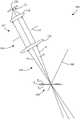
图1是示出根据本发明的实施例的光学轮廓测量系统的一个示例的透视图。FIG. 1 is a perspective view showing one example of an optical profile measurement system according to an embodiment of the present invention.
图2是示出光学轮廓测量系统的目标的一个示例的透视图。FIG. 2 is a perspective view showing one example of a target of the optical profilometry system.
图3是示出根据现有技术的光学轮廓测量系统的一个示例的透视图。FIG. 3 is a perspective view showing one example of an optical profile measurement system according to the related art.
图4是示出根据现有技术的光学轮廓测量系统的一个示例的示意图。FIG. 4 is a schematic diagram showing one example of an optical profilometry system according to the related art.
图5是示出根据现有技术的光学轮廓测量系统的一个示例的示意图。FIG. 5 is a schematic diagram showing one example of an optical profilometry system according to the related art.
图6是示出根据本发明的实施例的光学轮廓测量系统的一个示例的示意图。6 is a schematic diagram illustrating one example of an optical profile measurement system according to an embodiment of the present invention.
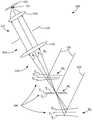
图7是示出光学轮廓测量系统的一个示例的示意图。FIG. 7 is a schematic diagram showing one example of an optical profilometry system.
图8是示出光学轮廓测量系统的一个示例的示意图。FIG. 8 is a schematic diagram showing one example of an optical profile measurement system.
图9是示出成像系统透镜组件的一个示例的底视图。FIG. 9 is a bottom view showing one example of an imaging system lens assembly.
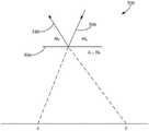
图10是示出光学轮廓测量系统的一个示例的示意图。FIG. 10 is a schematic diagram showing one example of an optical profile measurement system.
图11A是示出非理想聚焦环境的一个示例的示意图。FIG. 11A is a schematic diagram illustrating an example of a non-ideal focus environment.
图11B是示出非理想聚焦环境的一个示例的示意图。FIG. 11B is a schematic diagram illustrating an example of a non-ideal focus environment.
图12A是示出理想透镜焦平面环境的一个示例的示意图。12A is a schematic diagram illustrating one example of an ideal lens focal plane environment.
图12B是示出非理想透镜焦平面环境的一个示例的示意图。12B is a schematic diagram illustrating one example of a non-ideal lens focal plane environment.
图13是示出根据本发明的实施例的光学轮廓测量系统的一个示例的示意图。13 is a schematic diagram showing one example of an optical profile measurement system according to an embodiment of the present invention.
图14A是示出光学轮廓测量系统800的一个示例的顶视图。FIG. 14A is a top view illustrating one example of an
图14B是示出光学轮廓测量系统800的一个示例的透视图。FIG. 14B is a perspective view illustrating one example of the
图15A是示出光学轮廓测量系统的一个示例的示意图。FIG. 15A is a schematic diagram showing one example of an optical profilometry system.
图15B是示出聚焦在不同聚焦位置处的系统900的示意图。FIG. 15B is a schematic diagram showing the
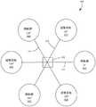
图16是示出根据本发明的实施例的光学轮廓测量系统的一个示例的示意图。FIG. 16 is a schematic diagram showing one example of an optical profile measurement system according to an embodiment of the present invention.
图17是示出根据本发明的实施例的光学轮廓测量系统的一个示例的示意图。FIG. 17 is a schematic diagram showing one example of an optical profile measurement system according to an embodiment of the present invention.
图18A至图18B是示出用于光学轮廓测量系统的校准方法的一个示例的流程图。18A-18B are flowcharts illustrating one example of a calibration method for an optical profilometry system.
图19是示出使用校准偏移量生成对应于镜像目标的图像的方法的一个示例的流程图。19 is a flowchart illustrating one example of a method of generating an image corresponding to a mirror target using a calibration offset.
图20是示出根据本发明的实施例的光学轮廓测量系统的一个示例的简化框图。20 is a simplified block diagram illustrating one example of an optical profilometry system according to an embodiment of the present invention.
图21是示出根据本发明的实施例的光学轮廓测量系统的一个示例的示意图。FIG. 21 is a schematic diagram showing one example of an optical profile measurement system according to an embodiment of the present invention.
具体实施方式Detailed ways
光学相位轮廓测量系统经常被用于各种工业和过程中以获得关于表面或物体的精确尺寸信息。例如,这些系统可以用于测量各种部件的高度和位置。例如,在电子工业中,许多电子组件包括安装在电路板上的装置。为了确保这种装置的正确尺寸和位置,照射源将照射投射到目标表面或物体上。从目标表面或物体反射的图像由成像系统(例如,相机)采集。光学相位轮廓测量系统通过在由成像系统采集的图像(例如像素)的特定点处测量被投射的照射的相位或位置来计算目标表面或物体的尺寸。Optical phase profilometry systems are often used in a variety of industries and processes to obtain precise dimensional information about surfaces or objects. For example, these systems can be used to measure the height and position of various components. For example, in the electronics industry, many electronic components include devices mounted on circuit boards. To ensure the correct size and location of such a device, the illumination source projects illumination onto the target surface or object. Images reflected from the target surface or object are acquired by an imaging system (eg, a camera). Optical phase profilometry systems calculate the size of a target surface or object by measuring the phase or position of the projected illumination at specific points in the image (eg, pixels) acquired by the imaging system.
这些装置中的一些具有镜像的、反射的表面,所述表面像反射表面一样仅沿一个方向反射光。因为针对镜像目标的尺寸测量值是目标的高度和倾斜度两者的函数,所以典型的光学相位轮廓测量系统难以获得关于镜像目标的精确尺寸信息。目标的位置(例如高度或倾斜度)可能受很多变量影响,例如但不限于设计选择、操作者或机器误差、不正确的联接(例如焊接)、不正确的放置以及各种其它误差。Some of these devices have mirrored, reflective surfaces that, like reflective surfaces, reflect light in only one direction. Because dimensional measurements for mirrored targets are a function of both the height and inclination of the target, it is difficult for typical optical phase profilometry systems to obtain precise dimensional information about mirrored targets. The location of the target (eg, height or inclination) may be affected by many variables, such as, but not limited to, design choices, operator or machine errors, incorrect joints (eg, welding), incorrect placement, and various other errors.
希望测量镜像表面,例如抛光的硅片。如果改变光学轮廓测量系统的几何结构,使得照射源和成像系统具有相等和相反的倾斜度,则镜像目标被成像,并且由于镜像目标比漫回射强大约1/(数值孔径)2的因子,所以至此镜像目标变成主导反射。试图假设这种感测几何结构像漫射几何结构一样起作用,即,如果漫射目标替换为镜像目标,则结果将是相同的。然而,情况并非如此。所导出的高度对光瞳的照度敏感,并且如果镜像目标被倾斜,则这个问题变得尤其明显,如上所述这是非常常见的情况。It is desirable to measure mirrored surfaces, such as polished silicon wafers. If the geometry of the optical profilometry system is changed so that the illumination source and the imaging system have equal and opposite inclinations, the mirror target is imaged, and since the mirror target is stronger than diffuse retroreflection by a factor of about 1/(numerical aperture)2 , So now the mirror target becomes the dominant reflection. Trying to assume that this sensing geometry behaves like a diffuse geometry, ie if the diffuse target was replaced with a mirror target, the results would be the same. However, this is not the case. The derived height is sensitive to the illumination of the pupil, and this problem becomes especially pronounced if the mirror target is tilted, which is a very common situation as described above.
随着对于获得用于镜像目标的精确尺寸信息的需要对于各种行业和过程变得越来越重要,需要一种光学轮廓测量系统,所述光学轮廓测量系统能够准确地测量镜像目标的尺寸并且校正镜像目标的反射效果。下面提供这样的系统、技术和方法。As the need to obtain accurate dimensional information for mirrored targets becomes increasingly important to various industries and processes, there is a need for an optical profilometry system that can accurately measure the dimensions of mirrored targets and Corrects reflections from mirrored targets. Such systems, techniques and methods are provided below.
虽然下面的一些附图示出了仅具有可操作的一对照射源和成像系统的光学轮廓测量系统,但是完全可以设想,可以使用具有可操作的多对照射源和成像系统的光学轮廓测量系统。Although some of the figures below show an optical profilometry system with only an operational pair of illumination source and imaging system, it is fully contemplated that an optical profilometry system with operational multiple pairs of illumination source and imaging system could be used .
图1是示出了根据本发明的实施例的光学轮廓测量系统的一个示例的透视图。系统100包括照射源102、成像系统104、目标106、照射108和反射110。如上所述,可以设想,在这样的系统中可以使用多个投影仪-相机对。照射源102相对于目标106定位,并向目标106投射照射108。成像系统104相对于目标106和照射源102定位。照射108被投射到目标106上,并且反射110被朝向成像系统104引导。照射108可以包括多个结构式光图案,例如重复的正弦强度图案或用于照射目标的任何其它合适的技术,使得可以获得关于该目标的尺寸信息。成像系统104被描绘为相机成像系统,相机成像系统配置成采集由照射源照射的目标的图像,但可包括用于采集由照射源投射的图像的任何数量的合适技术。FIG. 1 is a perspective view showing one example of an optical profilometry system according to an embodiment of the present invention.
如图1所示,用于照射源102和成像系统104的透镜组件是远心的,这由照射108和反射110二者的路径表示。如果使用非远心透镜组件,则来自照射源102的照射108在照射撞击目标106时将发散,并且反射110将错过成像系统104。通过使用远心透镜组件,源照射角和成像角在目标106上是相等的,确保在整个系统的视场上采集镜像反射。由照射源102生成的光进入多元件远心透镜组件,当光离开照射源102时变得基本平行并因此高度集中。因此,几乎所有由照射源102生成的光撞击目标106,并且反射110以镜像方式被朝向成像系统104引导。目标106被示出为镜像目标。目标106可以包括硅装置(例如,硅片),或者具有镜像表面或类似的镜表面的任何其它装置。As shown in FIG. 1 , the lens assemblies for
在一个实施例中,照射源102具有小的数值孔径。在一个实施例中,一个装置(照射源102或成像系统104)的光瞳完全包围另一个装置的光瞳。在一个实施例中,成像系统104的数值孔径足够大,以便针对目标106的所有可能的倾斜度接收照射108的全部投射的光线束。在另一个实施例中,照射源102的数值孔径足够大,以便针对目标106的所有可能的倾斜度完全充满成像系统104的数值孔径。在另一个实施例中,照射源102和成像系统104的数值孔径是相等的。In one embodiment, the
图2是示出光学轮廓测量系统目标的一个示例的透视图。目标106包括照射108和镜像装置150。照射108由照射源(例如源102)投射到目标106上。照射108被投射在镜像装置150上,使得关于镜像装置150的尺寸信息可由成像系统(例如,系统104)获得。目标106可以包括反射可变装置,反射可变装置包括镜像和漫射表面。例如,目标106可以包括具有诸如硅片的镜像装置(例如,装置150)的电路板。目标106可以是完全镜像装置或完全漫射装置。照射108可以是图案化的照射,诸如重复的正弦强度图案,或者任何其它照射技术,使得可以通过成像系统(例如,系统104)获得关于目标106或装置150的尺寸信息。FIG. 2 is a perspective view showing one example of an optical profilometry system target.
图3是示出根据现有技术的光学轮廓测量系统的一个示例的透视图。系统200包括照射源202、成像系统204、漫射目标206、照射208和反射210。系统200描述了根据现有技术的照射源202和成像系统204的典型配置。照射源202将照射208投射到漫射目标206上。反射210从漫射目标206反射,并且被成像系统204采集,使得可以获得关于漫射目标206的尺寸信息。FIG. 3 is a perspective view showing one example of an optical profile measurement system according to the related art.
图4是示出根据现有技术的光学轮廓测量系统的一个示例的示意图。系统200包括照射源202、成像系统204、漫射目标206、照射208、反射210、主光线211、被接收的光线束213和漫射反射路径254。系统200以与图3中相同的配置被示出,照射208被照射源202投射到漫射目标206上,并且反射210从漫射目标206反射,并且被接收的光线束213被成像系统204采集。主光线211表示朝向成像系统204的中心的光线路径。漫射目标206沿如由漫射路径254表示的所有方向散射入射光(例如,反射210)。因为入射光沿所有方向被散射,所以成像系统204可相对于目标206和照射源202放置在多个位置处且仍采集反射210的一部分。FIG. 4 is a schematic diagram showing one example of an optical profilometry system according to the related art.
图5是示出根据现有技术的光学轮廓测量系统的一个示例的示意图。系统200包括照射源202、成像系统204、目标106、照射208和反射110。系统200以与图3和4相同的配置被示出。目标106是镜像目标(例如,硅片)。照射208由照射源202投射到目标106上。反射110被从目标106反射,但不被成像系统204采集。因为目标106是镜像目标,所以来自照射源202的入射光沿由照射源202相对于目标106的入射角限定的方向从目标106反射。因此,反射110是镜像反射。也就是说,入射光(例如,照射208)沿单个出射方向反射,如照射110所示。因此,系统200的配置不能采集反射110,并且因此成像系统204不获得关于目标106的尺寸信息。FIG. 5 is a schematic diagram showing one example of an optical profilometry system according to the related art.
图6是示出根据本发明的实施例的光学轮廓测量系统的一个示例的示意图。系统100包括照射源102、成像系统104、目标106、照射108、反射110、主光线111、法向表面矢量160、入射角162和反射角164。系统100类似于图1中的系统100。成像系统104相对于目标106和照射源102配置,使得成像系统104的视角与由照射源102投射到目标106上的入射光(例如,照射108)的镜像反射(例如,反射110)对准。在所述配置中,成像系统104将采集来自镜像目标(例如,106)的镜像反射(例如,110),使得可以获得关于目标106的尺寸信息。主光线111表示朝向成像系统104的中心的光线路径。法向表面矢量160(在反射定律中也称为法线)描绘了在入射点处(即,在照射108撞击目标106的位置)垂直于目标106的表面绘制的直线,使得照射108与反射110之间的角度被分成相等的两半,如由入射角162和反射角164所表示的。但是因为目标106是镜像目标,所以反射110沿由入射角162限定的方向从目标106反射。因此,为了采集反射110,成像系统104与反射角164对准。6 is a schematic diagram illustrating one example of an optical profile measurement system according to an embodiment of the present invention.
图7是示出光学轮廓测量系统的一个示例的示意图。除了系统300示出了处于多个倾斜角处的目标106之外,系统300类似于系统100。系统300包括成像系统104、目标106、照射108、反射110、透镜组件112、孔径114、第一透镜116、第二透镜118、图像传感器120和接收点121。照射108由照射源(例如源102)投射到目标106上,照射从目标106朝向成像系统104反射。反射110穿过第一透镜116、孔径114和第二透镜118(即,透镜组件112)朝向图像传感器120。如图所示,目标106包括镜像目标,如从反射110的镜像特性可以看出的。透镜组件112包括远心透镜组件,如从光线束在其穿过第一透镜116朝向第二透镜118时的基本上平行的特性可以看出的。FIG. 7 is a schematic diagram showing one example of an optical profilometry system.
系统300获得关于在最佳聚焦高度处示出的目标106的尺寸信息。如上所述,根据目标的倾斜度,反射光线束将在不同的点处进入透镜组件中。在倾斜位置T1处,目标106处于基本上水平的角度(即,理想的最佳聚焦平面或理想平坦焦点)。在位置T1处,照射108从目标106朝向透镜组件112在透镜组件的中心处反射,如反射位置R1所表示的,从而导致正确测量目标106的高度。在倾斜位置T2处,目标106相对于T1向左(逆时针)倾斜。在倾斜位置T2处,照射108从目标106朝向透镜组件112离轴地反射,如反射位置R2所表示的。在倾斜位置T3处,目标106相对于T1向右(顺时针)倾斜度。在倾斜位置T3处,照射108从目标106朝向透镜组件112离轴反射,如反射位置R3所表示的。然而,因为反射110(如由R2和R3表示的)仍然由成像系统104采集,并且成像到图像传感器120上的相同点(即接收点121),虽然离轴,但是高度读数将被视为与T1的高度读数(如由R1表示的)相同。The
如上所述,水平目标将导致反射在透镜组件的中心处进入透镜组件中,而倾斜目标将导致反射离轴地进入透镜组件中。沿任何方向倾斜太多都将导致反射(或其一部分)错过透镜组件,从而不能被成像系统104采集,这将导致不准确的尺寸信息。对于具有比成像系统的数值孔径小的照射源数值孔径的系统,最大目标倾斜度应当被限制为小于:As mentioned above, a horizontal target will cause reflections to enter the lens assembly at the center of the lens assembly, whereas a tilted target will cause reflections to enter the lens assembly off-axis. Too much tilt in any direction will cause the reflection (or a portion thereof) to miss the lens assembly and not be captured by the
1/2(NACamera-NASource) 公式11/2(NACamera -NASource )
对于具有比成像系统的数值孔径大的照射源数值操作的系统,最大目标倾斜度应当被限制为小于公式1的负值。For systems operating numerically with an illumination source larger than the numerical aperture of the imaging system, the maximum target tilt should be limited to less than a negative value of
因为对于镜像目标,测量的相位是目标倾斜度和目标高度二者的函数,所以如果目标从成像系统的聚焦位置被移开,即使移开很小的量,也会出现问题。Because for mirrored targets, the measured phase is a function of both target tilt and target height, problems can arise if the target is removed from the imaging system's focus position, even by a small amount.
图8是示出光学轮廓测量系统的一个示例的示意图。除了系统400示出了在多个高度处的目标106之外,系统400类似于系统300。系统400包括成像系统104、目标106、照射108、反射110、透镜组件112、孔径114、第一透镜116、第二透镜118、图像传感器120和接收点121。照射108由照射源(例如源102)投射到目标106上,照射108从目标106反射离开朝向成像系统104。反射110穿过第一透镜116、孔径114和第二透镜118(即,透镜组件112)朝向图像传感器120。如图所示,如从反射110的镜像特性可以看出的,目标106包括镜像目标。透镜组件112包括远心透镜组件,如可以从光线束在其穿过第一透镜116朝向第二透镜118时的基本上平行的特性看出的。FIG. 8 is a schematic diagram showing one example of an optical profile measurement system.
高度位置H1类似于图7中目标106的位置,其中倾斜位置T1表示照射源104的理想的最佳聚焦平面。在高度位置H2处,目标106位于理想的最佳聚焦平面的上方。在倾斜位置T4处,目标106处于基本水平的角度。在倾斜位置T4处,照射108从目标106朝向透镜组件112在透镜组件的中心处反射,如反射位置R1所表示的,从而导致目标106的高度的正确测量值。在倾斜位置T5处,目标106相对于T4向左(逆时针)倾斜度。在倾斜位置T5处,照射108从目标106朝向透镜组件112离轴地反射,如反射位置R2所表示的,导致目标106的高度的不正确测量值。在倾斜位置T6处,目标106相对于T4向右(顺时针)倾斜。在倾斜位置T6处,照射108从目标106朝向透镜组件112离轴地反射,如反射位置R3所表示的,导致目标106的高度的不正确测量值。The height position H1 is similar to the position of the
在高度位置H3处,目标106位于理想的最佳聚焦平面的下方。在倾斜位置T7处,目标106处于基本上水平的角度(即,理想的最佳聚焦平面或理想平坦焦点)。在倾斜位置T7处,照射108从目标106朝向透镜组件112在透镜组件中心处反射,如反射位置R1所表示的,从而导致目标106的高度的正确测量值。在倾斜位置T8处,目标106相对于T7向右(顺时针)倾斜。在倾斜位置T8处,照射108从目标106朝向透镜组件112离轴地反射,如反射位置R2所表示的,导致目标106的高度的不正确测量值。在倾斜位置T9处,目标106相对于T7向左(逆时针)倾斜。在倾斜位置T9处,照射108从目标106朝向透镜组件112离轴地反射,如反射位置R3所表示的,导致目标106的高度的不正确测量值。At height position H3,
在最佳焦点的上方,沿顺时针方向倾斜的目标将测量成高于目标的实际高度位置。沿逆时针方向倾斜的目标将测量成低于目标的实际高度位置。当目标进一步移动离开成像系统的最佳聚焦位置时,高度测量值对倾斜角的误差灵敏度将增加。当目标从目标的最佳聚焦平面的上方移动到下方时,误差的符号也翻转,如通过T6与T8以及T5与T9的比较可以看出的。T6和T8都顺时针地倾斜,并且都具有相等的反射角。照射108从两者朝向透镜组件112离轴地反射。然而,因为光线束最初从目标106反射,如R3所表示的,所以在T6(在目标的最佳聚焦平面之上,例如T1)处,反射110位于光线束的右侧。而对于T8(在目标的最佳聚焦平面的下方,例如T1),因为光线束最初从目标106反射,如R2所表示的,所以反射110位于光线束的左侧。类似地,比较T5和T9,两者都逆时针地倾斜,并且两者都具有相等的反射角。照射108从两者朝向透镜组件112离轴地反射。然而,因为光线束最初从目标106反射,如R2所表示的,所以在T5(在目标的最佳聚焦平面之上,例如T1)处,反射110位于光线束的左侧。而对于T9(在目标的最佳聚焦平面的下方,例如T1),因为光线束最初从目标106反射,如R3所表示的,所以反射110位于光线束的右侧。Above the best focus, a target tilted in a clockwise direction will measure above the target's actual height position. A target tilted in a counterclockwise direction will measure below the target's actual altitude position. As the target moves further away from the best focus position of the imaging system, the error sensitivity of the height measurement to tilt angle will increase. The sign of the error also flips as the target moves from above to below the target's plane of best focus, as can be seen by comparing T6 with T8 and T5 with T9. Both T6 and T8 are tilted clockwise and both have equal reflection angles.
测量高度对目标倾斜角的灵敏度可以被认为是系统的三角测量角的变化。顺时针倾斜的目标比正常(理想)系统的三角测量角有效地具有更小的三角测量角。逆时针倾斜的目标比正常(理想)系统的三角测量角有效地具有更大的三角测量角。The sensitivity of the measurement height to the target tilt angle can be thought of as a change in the triangulation angle of the system. A clockwise tilted target effectively has a smaller triangulation angle than that of a normal (ideal) system. A counter-clockwise tilted target effectively has a larger triangulation angle than that of a normal (ideal) system.
图7和图8中所示的倾斜导致获得关于目标106的精确尺寸信息的问题。例如,即使T6和T5处于与T4不同的高度处,因为反射110(分别由R3和R2表示)仍然被成像系统104采集并且成像到图像传感器120上的同一点(即,在接收点121处),尽管离轴,但是高度读数将被看作与T4的高度读数相同。类似地,对于T9和T8,即使T9和T8处于与T7不同的高度,因为反射110(分别由R2和R3表示)仍然被成像系统104采集,所以尽管离轴,但是高度读数将被视为与T7的高度读数相同。当具有不同高度和倾斜度(例如T4和T7)的目标具有基本相同的位置时,这使得光学相位轮廓检测系统(例如100、300和400)在不同高度和不同倾斜度(例如T5、T6、T8和T9)处读取目标。The tilt shown in FIGS. 7 and 8 leads to problems in obtaining precise dimensional information about the
图9是示出成像系统透镜组件的一个示例的底视图。透镜组件112包括反射110和第一透镜116。如上所述,目标倾斜度导致反射110的光线束在不同的点处进入透镜组件112中。对于具有基本上水平角度(例如,T1、T4或T7)的目标,反射110将在由反射位置R1表示的透镜组件中心处进入透镜组件112中,从而导致目标的高度的正确测量值。对于具有逆时针倾斜度(例如T2、T5或T9)的目标,反射110将离轴地进入透镜组件112中,如反射位置R2所表示的,导致目标的高度的不正确测量值。对于具有顺时针倾斜度(例如T3、T6或T8)的目标,反射将离轴地进入透镜组件112中,如反射位置R3所表示的,导致目标的高度的不正确测量值。FIG. 9 is a bottom view showing one example of an imaging system lens assembly.
测量高度对目标倾斜角的灵敏度可以被认为是系统的三角测量角的变化。顺时针倾斜的目标比正常(即理想的最佳聚焦)系统的三角测量角有效地具有更小的三角测量角。逆时针倾斜的目标比正常(即理想的最佳聚焦)系统的三角测量角有效地具有更大的三角测量角。The sensitivity of the measurement height to the target tilt angle can be thought of as a change in the triangulation angle of the system. A clockwise tilted target effectively has a smaller triangulation angle than that of a normal (ie ideal best focus) system. A counter-clockwise tilted target effectively has a larger triangulation angle than that of a normal (ie, ideal best focus) system.
如上所述,镜像目标的导出高度对光瞳的照度敏感,并且如果镜像目标倾斜度,则该问题变得尤其关键。这可能引起各种问题,例如但不限于获得关于目标的不准确的尺寸信息,或者所采集的图像的渐晕。为了更好地理解问题的本质,考虑具有远心光学装置并且在各处进行单位放大的理想化2-D轮廓测量仪,如下图中所描绘的。As mentioned above, the derived height of the mirror target is sensitive to the illumination of the pupil, and this problem becomes especially critical if the mirror target is tilted. This can cause various problems such as, but not limited to, obtaining inaccurate dimensional information about the target, or vignetting of the acquired image. To better understand the nature of the problem, consider an idealized 2-D profilometer with telecentric optics and unit magnification everywhere, as depicted in the figure below.
图10是示出光学轮廓测量系统的一个示例的示意图。系统500包括镜像目标506、照射508和反射510。照射508从照射源(未示出)以对应于所选三角测量角(例如入射角162)的斜度mS投射。照射508落在镜像目标506上,其中镜像目标506具有斜度mt。然后,照射508沿方向mr朝向成像系统(未示出)反射为反射510。出于描述的目的,照射源和成像系统二者聚焦在zt处。由此,这意味着源自照射源的光瞳上的指定点的照射源的投射的光线束(例如,照射508)会聚到在zt处的公共点,并且从zt处的指定的目标点发出的从镜像目标506反射的光线束(例如,反射510)会聚到成像系统的光瞳上的公共点处。因此,在照射源的光瞳或成像系统的光瞳上的位置与这种光线与x轴相交的位置之间存在一一对应关系。另外,出于该描述的目的,成像系统不使任何反射光线束渐晕。因此,光线束的形心与主光线重合,主光线是在成像系统的光瞳的中心处的光线。这样,通过仅跟踪主光线,可以简化推导(出于说明的目的)。FIG. 10 is a schematic diagram showing one example of an optical profile measurement system.
照射源光线(例如照射508)具有以下公式:An illumination source ray (eg, illumination 508 ) has the following formula:
x=s+msz 公式2x=s+ms z Equation 2
并且成像系统光线(例如反射510)具有以下公式:And the imaging system rays (eg reflection 510) have the following formula:
x=r-mrz 公式3x=rmr z Equation 3
利用这些限定,成像系统的光线角是目标角加上照射源角的两。在解析几何的术语中,我们有以下公式:With these constraints, the ray angle of the imaging system is the target angle plus the illumination source angle twice. In the terminology of analytic geometry, we have the following formula:

其中w是均一的权重。对此进行评估,我们有where w is the uniform weight. Evaluating this, we have

从图10所示的几何结构中,显然地From the geometry shown in Figure 10, it is obvious that
r-s=zt(ms+mr) 公式6rs=zt (ms +mr ) Equation 6
并且因此and therefore

在泰勒级数中展开公式7是有用的,其中It is useful to expand Equation 7 in a Taylor series, where

实际上,我们观察到r-s,并希望导出zt。公式8的结果r-s是如相机系统所看到的结构式光图案的观察到的偏移量。公式8示出了重构高度zt对目标斜度mt的依赖性。对于任意目标,公式8归纳为如下的非线性微分方程:In fact, we observe rs and wish to derive zt . The result rs of Equation 8 is the observed offset of the structured light pattern as seen by the camera system. Equation 8 shows the dependence of the reconstruction height zt on the target slope mt . For any target, Equation 8 reduces to the following nonlinear differential equation:

为了计算目标轮廓z,必须求解公式9。如果要计算精确的目标轮廓,则由于镜像反射的性质,对镜像目标进行成像的光学相位轮廓测量仪还必须用作弯度计是相当复杂的。In order to calculate the target contour z, Equation 9 must be solved. If an exact target profile is to be calculated, due to the nature of mirror reflections, the optical phase profilometer that images the mirrored target must also function as a clinometer.
用于测量漫射目标的传统的相位轮廓测量系统被校准以校正成像系统透镜组件和照射源透镜组件的几何失真。如上所示,镜像相位轮廓测量系统对成像系统的聚焦位置(相对于目标)和反射光线束的接收光线角是敏感的。镜像相位轮廓测量系统还对附加的透镜像差是敏感的。这种附加的像差包括但不限于场曲率和球面像差。为了说明而不是限制的目的,下面描述的透镜像差校正方法考虑了场曲率和球面像差,但是也可以用于校正其它的透镜特性。所述方法的描述将首先从讨论两种类型的透镜像差开始。Conventional phase profilometry systems used to measure diffuse targets are calibrated to correct for geometric distortions of the imaging system lens assembly and the illumination source lens assembly. As shown above, the mirror phase profilometry system is sensitive to the focus position of the imaging system (relative to the target) and the received beam angle of the reflected beam. Mirror phase profilometry systems are also sensitive to additional lens aberrations. Such additional aberrations include, but are not limited to, field curvature and spherical aberration. For purposes of illustration and not limitation, the lens aberration correction method described below takes into account field curvature and spherical aberration, but may also be used to correct for other lens properties. The description of the method will first begin by discussing two types of lens aberrations.
场曲率是聚焦位置在成像系统的视场上的变化。最佳聚焦高度是在场上倾斜并弯曲的表面,而不是在平坦和水平的平面上的最佳聚焦。场曲率的像差将在下文描述。Field curvature is the change in focus position over the field of view of the imaging system. The best focus height is on a sloped and curved surface on the field, not on a flat and horizontal plane. The aberration of field curvature will be described below.
图11A是示出理想平坦的聚焦环境的一个示例的示意图。环境600包括聚焦平面606和反射610。在如环境600的理想平坦聚焦环境中,理想成像系统聚焦到如聚焦平面606的平坦且水平的聚焦平面上。然而,在真实环境中,成像系统并不以与其在理想环境中的方式相同的方式而聚焦。FIG. 11A is a schematic diagram showing one example of an ideally flat focusing environment.
图11B是示出非理想聚焦环境的一个示例的示意图。环境650包括理想的聚焦平面652、非理想的聚焦平面656和反射660。在如环境650的非理想的聚焦环境中,目标不能聚焦在平坦的图像平面(例如,理想的聚焦平面652)上。在这种环境中,光学轴线(即透镜的中心点)附近的光线束(例如反射660)将聚焦在理想的聚焦平面处,如利用具有与理想的聚焦平面652重合的聚焦平面高度的中间光线束可以看出的。然而,对于离轴光线束,如像图中的左光线束和右光线束那样,聚焦位置从理想的聚焦平面652移开,如可以通过非理想的聚焦平面656看出的。该像差可能引起图像失真,例如但不限于模糊、不清楚、图像的外观离焦等。FIG. 11B is a schematic diagram illustrating an example of a non-ideal focus environment.
球面像差导致聚焦位置随光线角的偏移。边缘光线聚焦在与近轴光线不同的高度处。对于具有正球面像差的典型透镜,边缘光线将比近轴光线更靠近透镜聚焦。球面像差在以下附图中描述。Spherical aberration causes a shift in focus position with ray angle. The marginal rays are focused at a different height than the paraxial rays. For a typical lens with positive spherical aberration, marginal rays will focus closer to the lens than paraxial rays. Spherical aberrations are described in the following figures.
图12A是示出理想的透镜聚焦平面环境的一个示例的示意图。环境700描绘了没有任何球面像差的理想的透镜聚焦平面。环境700包括聚焦平面702、主轴704、边缘光线706和近轴光线708。主轴704描绘了透镜(未示出)的中心。如在环境700中可以看到的,利用没有球面像差的理想透镜,边缘光线706和近轴光线708二者聚焦在相同位置处。12A is a schematic diagram illustrating one example of an ideal lens focal plane environment.
图12B是示出非理想的透镜焦平面环境的一个示例的示意图。环境750描绘了具有球面像差的透镜的聚焦平面,具体地,具有正球面像差的典型透镜的聚焦平面。环境750包括近轴聚焦平面752、边缘聚焦平面754、主轴756、边缘光线758和近轴光线760。主轴756描绘了透镜(未示出)的中心。如在环境750中可以看到的,具有球面像差的透镜引起聚焦位置的偏移。边缘聚焦平面754与近轴聚焦平面752相比更靠近透镜组件。聚焦位置相对于每组光线的这种偏移可以导致目标的采集的图像的异常。例如但不限于模糊、不清楚、图像的外观失焦等。12B is a schematic diagram illustrating one example of a non-ideal lens focal plane environment.
为了获得关于光学轮廓测量系统的各种目标的精确尺寸信息,必须校正诸如上述那些透镜像差和其它形式的透镜像差。一个实施例被证明具有未由公式9预测的目标梯度的变化,在所述实施例中,成像系统透镜被设计成具有受控量的球面像差,以便抑制混叠效应。在所述实施例中,当目标倾斜时,返回光(即反射)被扫出成像系统透镜的光瞳。由于球面像差,形心被目标梯度中的三次项扰动。然而,可以应用后补偿以至少部分地校正该问题,从而提高高度测量值的精度。引入方位角矢量In order to obtain accurate dimensional information about the various objects of an optical profilometry system, lens aberrations such as those described above and other forms of lens aberrations must be corrected. One embodiment demonstrated to have a variation in target gradient not predicted by Equation 9, in which the imaging system lens is designed with a controlled amount of spherical aberration, in order to suppress aliasing effects. In the described embodiment, when the target is tilted, the returned light (ie reflection) is swept out of the pupil of the imaging system lens. Due to spherical aberration, the centroid is perturbed by a cubic term in the target gradient. However, post compensation can be applied to at least partially correct for this problem, thereby improving the accuracy of the height measurements. Introduce azimuth vector

在成像系统的方位角是λ的情况下,我们预期形式的误差zIn the case where the azimuth of the imaging system is λ, we expect an error of the form z

其中c是常数,以及where c is a constant, and

是z沿方向v的导数。is the derivative of z along the direction v.
实际上发现,在计算梯度时,公式12的噪声对计算具有非常有害的影响。一些低通滤波是必要的。首先根据以下公式计算校正的图像L=LPF(r-s) 公式13In fact, it was found that the noise of Equation 12 has a very detrimental effect on the calculation when calculating the gradient. Some low pass filtering is necessary. First calculate the corrected image L=LPF(r-s) according to Equation 13
以及(r-s)correctedand (r-s)corrected

其中r-s是未校正的几何位移,P3()是描述光学像差对检测的位置偏移量r-s具有的影响的3次三变量多项式:where rs is the uncorrected geometric displacement and P3 ( ) is a 3rd degree trivariate polynomial describing the effect optical aberrations have on the detected position offset rs:

此计算是方便的,但是低通滤波降低了最终图像的锐度。为了避免这个问题,设计了一种改进的代码,其中低通滤波只影响校正的计算:This calculation is convenient, but low-pass filtering reduces the sharpness of the final image. To avoid this problem, an improved code is devised in which the low-pass filtering only affects the computation of the correction:

用于光学轮廓测量系统对镜像目标成像的一个重要应用是对集成无源装置的测量。集成无源装置是具有镜像顶部的小的矩形部件。由于从梯度导出的估计所引起的噪声以及集成无源装置的顶表面的平滑度(即,镜像特性),希望通过双变量多项式来对集成无源装置进行建模。在这种情况下,可以将球面像差和偏转测量校正二者建模为z的真实目标梯度的函数。因此,公式9变为:An important application for imaging mirrored targets with optical profilometry systems is the measurement of integrated passive devices. Integrated passives are small rectangular components with mirrored tops. Due to the noise caused by the gradient-derived estimates and the smoothness of the top surface of the integrated passive device (ie, mirror-image properties), it is desirable to model the integrated passive device by a bivariate polynomial. In this case, both spherical aberration and deflection measurement corrections can be modeled as functions of the true target gradient of z. Therefore, Equation 9 becomes:

球面像差校正对应于公式14中的三变量多项式。The spherical aberration correction corresponds to the three-variable polynomial in Equation 14.
校准的作用对于光学轮廓测量系统,特别是那些成像镜像目标来说是至关重要的。希望将校准公式设置为线性系统。可能提出的目标是必须以某种方式反演公式17以获得重建算法,但是通过选择显式(非迭代)校正模型,可能迫使校准例程中的线性最小二乘拟合处理所有反演,使得运行时间校正可以是单一的显式公式:The role of calibration is critical for optical profilometry systems, especially those imaging mirror targets. It is desirable to set the calibration formula as a linear system. A possible proposed goal is that Equation 17 must be inverted in some way to obtain the reconstruction algorithm, but by choosing an explicit (non-iterative) correction model, it is possible to force the linear least squares fit in the calibration routine to handle all inversions such that The runtime correction can be a single explicit formula:

在这个单一的显式公式中,P()是其像素坐标和方向导数的参数中的三变量多项式。第一项处理镜像重建,并且第二项处理球面像差校正。In this single explicit formulation, P() is a three-variable polynomial in its parameters for pixel coordinates and directional derivatives. The first term deals with mirror reconstruction and the second term deals with spherical aberration correction.
除了上述透镜像差之外,可能影响获得关于目标的准确尺寸信息的另一个非理想性是光瞳渐晕效应。在任何实际的光学轮廓测量系统中,照射源具有数值孔径,数值孔径限定从目标上的每个点射出的光线束的边界。通常,系统将被对准,使得对于非倾斜目标,照射源的光瞳的中心将与成像系统的光瞳的中心相交。然而,如上所述,目标的任何倾斜都会干扰这种对准。In addition to the aforementioned lens aberrations, another non-ideality that may affect obtaining accurate dimensional information about an object is pupil vignetting effects. In any practical optical profilometry system, the illumination source has a numerical aperture that defines the boundaries of the beam of light emerging from each point on the target. Typically, the system will be aligned such that for a non-tilted target, the center of the pupil of the illumination source will intersect the center of the pupil of the imaging system. However, as mentioned above, any tilt of the target will interfere with this alignment.
另外,成像系统具有其自己的数值孔径。如果两个数值孔径是可比较的,则一个数值孔径可以具有孔径部分重叠的情况。因此,在一种已知为渐晕的现象中,孔径可以限制光线束的横截面。因为如上在图8和图10中所述的光学轮廓测量仪的基本几何结构假定光线束的形心正好偏离目标倾斜度的两倍,所以这使图像重建复杂化。然而,随着渐晕,光线束的形心以及因此有效的三角测量角是更复杂的倾斜度的函数。原则上,可以校准和补偿这种与理想性(即,如图8和图10中所描述的假定的几何结构)的偏差。然而,因为两个孔径函数的边缘是尖锐的,所以校准曲线将具有斜度不连续性。这种不连续性妨碍了通常的多变量多项式很好地拟合。Additionally, the imaging system has its own numerical aperture. If the two numerical apertures are comparable, one numerical aperture may have partial overlap of the apertures. Thus, in a phenomenon known as vignetting, the aperture can limit the cross-section of a beam of light. This complicates image reconstruction because the basic geometry of the optical profilometer as described above in Figures 8 and 10 assumes that the centroid of the ray bundle is offset by exactly twice the inclination of the target. However, with vignetting, the centroid of the ray bundle and thus the effective triangulation angle is a more complex function of slope. In principle, this deviation from ideality (ie the assumed geometry as described in Figures 8 and 10) can be calibrated and compensated for. However, because the edges of the two aperture functions are sharp, the calibration curve will have slope discontinuities. This discontinuity prevents the usual multivariate polynomials from fitting well.
在一个实施例中,为了避免这种问题,一个光瞳必须完全包围另一个光瞳(即,成像系统的光瞳完全包围照射源的光瞳,反之亦然)。在一个实施例中,照射源的数值孔径小于成像系统的数值孔径。在另一个实施例中,照射源的数值孔径大于成像系统的数值孔径。在另一个实施例中,照射源的数值孔径和成像系统的数值孔径是相等的。In one embodiment, to avoid this problem, one pupil must completely surround the other pupil (ie, the pupil of the imaging system completely surrounds the pupil of the illumination source and vice versa). In one embodiment, the numerical aperture of the illumination source is smaller than the numerical aperture of the imaging system. In another embodiment, the numerical aperture of the illumination source is greater than the numerical aperture of the imaging system. In another embodiment, the numerical aperture of the illumination source and the numerical aperture of the imaging system are equal.
也存在与求解公式9以导出轮廓z相关联的困难,一个这种问题是如果要测量较小的特征(如在光学轮廓测量系统的应用中的通常的情况),则用于估计目标梯度的基线是较小的。因此,所检测的相位(z高度位置)中的较小的误差可能引起梯度中的较大的误差,这通过公式9可能极大地干扰所重构的轮廓。在数值分析方面,问题是劣性的。换句话说,输入数据中的较小的误差导致重构中的较大的误差。There are also difficulties associated with solving Equation 9 to derive the profile z, one such problem is that if smaller features are to be measured (as is usually the case in the application of optical profilometry systems), the The baseline is smaller. Therefore, a small error in the detected phase (z height position) may cause a larger error in the gradient, which by Equation 9 may greatly disturb the reconstructed contour. In terms of numerical analysis, the problem is inferior. In other words, smaller errors in the input data lead to larger errors in the reconstruction.
一种避免这个问题的方法是用多个照射源-成像系统对来观察目标。如上所述,本发明完全设想了仅使用一对照射源-成像系统的光学相位轮廓测量系统。另外,本发明还完全设想了使用多个照射源-成像系统对的光学相位轮廓测量系统。虽然每个系统可以获得关于目标的精确的尺寸信息,但是每个系统提供了独特的优点。例如,对于单对系统,可以(利用上述技术和方法)更有效和以更成本有效的方式获得精确的尺寸信息。通过仅使用单对系统,安装更容易,制造和维护更便宜,同时具有其它优点。对于某些目标(例如,具有可在图像上投射阴影的具有变化的高度尺寸的部件的目标),通过例如从多个视角观察目标(从而减少与阴影相关联的问题),使用多对系统是有利的。One way to avoid this problem is to use multiple illumination source-imaging system pairs to view the target. As mentioned above, the present invention fully contemplates an optical phase profilometry system using only a pair of illumination source-imaging systems. Additionally, the present invention fully contemplates optical phase profilometry systems using multiple illumination source-imaging system pairs. While each system can obtain precise dimensional information about the target, each system provides unique advantages. For example, for a single-pair system, accurate dimensional information can be obtained (using the techniques and methods described above) more efficiently and in a more cost-effective manner. By using only a single pair system, installation is easier, manufacturing and maintenance are cheaper, among other advantages. For some targets (eg, targets with parts with varying height dimensions that can cast shadows on the image), using a multiple-pair system is useful, for example, by viewing the target from multiple viewpoints (thus reducing problems associated with shadows). advantageous.
在利用多个照射源-成像系统对、使用任意方位角来观察目标的系统中,用于第k对的公式9变为:In a system that utilizes multiple illumination source-imaging system pairs to observe the target using arbitrary azimuth angles, Equation 9 for the k-th pair becomes:

其中v=[cosφ,sinφ]。在公式19中,上述麻烦的斜度项用方位角向量vk标示。如果存在多个方位角,则可以形成加权和,使得梯度项对于任何梯度都抵消:where v=[cosφ, sinφ]. In Equation 19, the troublesome slope term described above is denoted by the azimuth vectorvk . If there are multiple azimuths, a weighted sum can be formed such that the gradient term cancels out for any gradient:
∑wk(r-s)k=2zms∑mk 公式20∑wk (rs)k = 2zms ∑mk Equation 20
没有梯度项,重建被极大地简化。发生期望的抵消,此时∑wkvk=0 公式21Without the gradient term, the reconstruction is greatly simplified. Desired cancellation occurs when ∑wk vk = 0 Equation 21
或wTV=0。这是零子空间问题,如果V不是完全行秩,则其具有非常规的解。为了说明的目的,将针对使用三个照射源-成像系统对的系统来解释所述问题:or wT V=0. This is a null subspace problem, which has an unconventional solution if V is not fully row-rank. For illustration purposes, the problem will be explained for a system using three illumination source-imaging system pairs:

如果我们计算v矩阵的QR因式分解,我们得到If we compute the QR factorization of the v matrix, we get

其中~表示一些非零元素。条件被认为满足where ~ represents some non-zero element. condition is considered satisfied
wTQ=[0 0 1] 公式24wT Q=[0 0 1] Equation 24
这导致This leads to

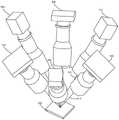
图13示出根据本发明的实施例的光学轮廓测量系统的一个示例的示意图。系统800包括照射源802、806、810,成像系统804、808、812,光学轴线814、816、818,以及目标820。系统800是三个照射源-成像系统对的光学轮廓测量系统。如上所述,这种系统在以下方面是有利的,系统被配置成以多个不同的视角采集目标的图像。由此,系统可以减少例如阴影的光学效应,以及其它优点。系统800的对准几何结构示出了每个照射源与其它照射源成120度对准。类似地,每个成像系统与其它成像系统成120度对准。分别对应于单独照射源-成像系统对的光学轴线814、816及818描绘了用于每一个相应的照射源-成像系统对的透镜组件的焦点及中心。例如,光学轴线814对应于照射源802-成像系统804对的透镜组件的焦点和中心。目标820是镜像目标,但是可以包括任何数量的目标,目标包括但不限于漫射目标、具有镜像的表面和漫射的表面的组合目标或部件等。13 shows a schematic diagram of one example of an optical profilometry system according to an embodiment of the present invention.
系统800的几何对准导致权重项wk都是相等的。虽然系统800中描绘的对准几何结构示出120度的间隔,但是可以设想其它对准几伺结构。对于这种系统的唯一要求是两个成像系统没有出现在相同的方位角处,并且因为照射源和成像系统被配置成通过限定照射源的方位角来对镜像目标进行成像,因此必须限定成像系统的方位角。换句话说,为了采集目标的镜像图像,对于双相机轮廓测量系统,成像系统必须放置成在方位角上距照射源180度。虽然系统800被示出为三个照射源-成像系统对的光学轮廓测量系统,但是本发明设想也可以在光学轮廓测量系统中使用其它对的组合。例如,只要成像系统分开180度,也可以使用两个照射源-成像系统对的系统。The geometric alignment of the
图14A是示出光学轮廓测量系统800的一个示例的顶视图。系统800包括照射源802、806、810,成像系统804、808、812,光学轴线814、816、818,以及目标820。FIG. 14A is a top view illustrating one example of an
图14B是示出光学轮廓测量系统800的一个示例的透视图。系统800包括照射源802、806、810,成像系统804、808、812,光学轴线814、816、818,以及目标820。FIG. 14B is a perspective view illustrating one example of the
如上所述,避免z高度噪声对公式9的影响的另一种方式是在不同的聚焦位置处进行两次测量。As mentioned above, another way to avoid the effect of z-height noise on Equation 9 is to take two measurements at different focus positions.
图15A是示出光学轮廓测量系统的一个示例的示意图。系统900包括镜像目标906、照射908、反射910、主光线922、接收光线924、聚焦位置a926、理想的聚焦平面928、撞击点930、932和934。照射908由照射源投射并在撞击点930处撞击镜像目标906。然后,如反射910所示,照射908朝向成像系统反射。反射910包括主光线922以及接收光线,主光线表示在透镜组件中心处进入成像系统的透镜组件的光线,接收光线表示来自具有倾斜度的目标,例如目标906,的离轴反射光线的方向。聚焦位置926表示系统900的成像系统聚焦所在的平面。如之前在上文所述,理想的聚焦平面928表示用于理想系统的理想的聚焦平面。FIG. 15A is a schematic diagram showing one example of an optical profilometry system.
出于说明而不是限制的目的,系统900的成像系统和照射源具有对准,其中成像系统和照射源的斜度是ms。在图15A中,照射908在位置xta、zta处与镜像目标906相交。主光线922在位置xt、zt处与目标906相交。聚焦位置926位于高度位置za处。主光线922和接收光线924在位置xa、za处与聚焦位置926相交。理想的聚焦平面928位于高度位置z=0处。反射910在位置r处与理想的聚焦平面928相交。照射908在位置sa处与理想的聚焦平面928相交。接收光线924具有斜度mr。镜像目标906具有斜度mt。主光线922的位置可以通过x=r-msz来找到。照射908的位置可以通过x=sa+msz来找到。镜像目标906的位置可以通过x=xt+(z-zt)/mt来找到。For purposes of illustration and not limitation, the imaging system and illumination source of
图15B是聚焦在不同聚焦位置的系统900的示意图。除了图15B中的成像系统聚焦在聚焦位置936处之外,图15B中的系统900类似于图15A中的系统900。Figure 15B is a schematic diagram of the
在图15B中,照射908在位置xtb、ztb处与目标906相交。主光线922在位置xt、zt处与镜像目标906相交。聚焦位置b936位于高度位置zb处。主光线922和接收光线924在位置xb、zb处与聚焦位置b936相交。理想的聚焦平面928位于高度位置z=0处。反射910在位置r处与理想的聚焦平面928相交。照射908在位置sb处与理想的聚焦平面928相交。接收光线924具有斜度mr。镜像目标906具有斜度mt。主光线922的位置可以通过x=r-msz来找到。照射908的位置可以通过x=sb+msz来找到。镜像目标906的位置可以通过x=xt+(z-zt)/mt来找到。In Figure 15B,
从图15A和15B可以看出,成像系统接收从目标反射的具有斜度mr的光。该接收光线在成像系统的聚焦位置(聚焦平面)处与主光线相交(忽略球面像差)。对于聚焦位置926,该相交发生在位置xa、za处。对于聚焦位置936,该相交出现在位置xb、zb处。接收光线在用于聚焦位置926的位置xTa、zta处和用于聚焦位置936的位置xtb、ztb处与目标相交。穿过xta、ztz的照射在x=sa处与理想的聚焦平面相交。穿过xtb、ztb的照射在x=sb处与理想的聚焦平面相交。因此,当成像系统聚焦在可变聚焦位置(例如926和936)处时,可变源位置(例如sa和sb)被发现。As can be seen from Figures 15A and 15B, the imaging system receives light reflected from the target with a slopemr . This received ray intersects the chief ray (ignoring spherical aberration) at the focal position (focus plane) of the imaging system. For
在运行时间,基于用于像素r的测量的源位置sa、sb估计目标位置zt和mt。为了方便,限定两个变量,两个测量的源位置的平均值及两个测量的源位置之间的差值:At runtime, target positions zt and mt are estimated based on the measured source positions sa , sb for pixel r. For convenience, two variables are defined, the mean of the two measured source locations and the difference between the two measured source locations:

Δs=Sa-Sb 公式27Δs=Sa -Sb Equation 27
目标高度和目标倾斜度都可以通过下式提取:Both target height and target inclination can be extracted by:


利用这种方法,透镜像差(例如球面像差)高度校正采取P(α,β,Δs)的形式。将该因子加到使用公式28计算的zt上。With this approach, lens aberrations (eg spherical aberration) are highly corrected in the form of P(α, β, Δs). Add this factor to the zt calculated using Equation 28.
为了效率,希望针对两个聚焦位置同时获得关于目标的尺寸信息。这可以通过使用包括分束器和两个相机的成像系统来实现。这种系统将在下面的附图中描述。For efficiency, it is desirable to obtain size information about the target simultaneously for both focus positions. This can be achieved by using an imaging system including a beam splitter and two cameras. Such a system will be described in the following figures.
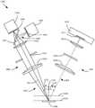
图16是示出根据本发明的实施例的光学轮廓测量系统的一个示例的示意图。系统1000包括照射源1002、成像系统1004、镜像目标1006、照射1008、反射1010、主光线1011、法向矢量1020、反射角1021、入射角1022、聚焦位置1024以及聚焦位置1026。照射源1002包括照射生成器1012(例如,结构式光生成器)、空间光调制器1013(例如,数字微镜装置)、透镜1014、孔径1016和透镜1018。照射源1002可以包括数字光处理(DLP)、透射液晶、硅上液晶(LCOS)以及用于投射结构式式光图案的任何其它合适的技术。成像系统1004包括透镜1028、孔径1030、透镜1032、相机1034、图像平面1036、相机1038、图像平面1040、分束器1042和分束器1044。系统1000包括远心透镜系统,远心透镜系统结合了两个相机(例如1034和1038),并且每个相机观察相同的目标(例如1006)并共享相同的透镜轴线。FIG. 16 is a schematic diagram showing one example of an optical profile measurement system according to an embodiment of the present invention.
照射1008由照射源1002投射到目标1006上,照射1008从目标1006朝向成像系统1004反射,如反射1010所示。当反射1010穿过成像系统1004时,反射1010到达分束器1042。分束器1042(50-50分束器)为相机1034和1038两者提供光学路径。因此,反射1010由相机1034的图像平面1036及相机1038的图像平面1040两者接收。相机1034的图像平面1036相对于分束器1042定位,使得图像平面1036的聚焦位置是聚焦位置1024。相机1038的图像平面1040相对于分束器1042定位,使得图像平面1040的聚焦位置是聚焦位置1026。换句话说,在与聚焦位置1024重合的高度位置处的目标将针对相机1034聚焦,并且在与聚焦位置1026重合的高度位置处的目标将针对相机1038聚焦。系统1000的并行采集定时允许系统在两个不同的聚焦位置(例如1024和1026)处同时采集目标1006的图像。
虽然在图16中示出了照射源1002的数值孔径1016小于成像系统1004的数值孔径1030,但是在可替代实施例中,本发明设想照射源的数值孔径大于成像系统的数值孔径。在另一个实施例中,照射源和成像系统两者的数值孔径是相等的。16 shows that the
另一种用于针对多个聚焦位置获得关于目标的尺寸信息的技术是具有可调节部件的光学轮廓测量系统。如果允许额外的采集时间,则可以使用可调节光学系统来顺序地针对多个聚焦位置的获得关于目标的尺寸信息。可调节光学系统的优点在于可调节光学系统可以适应放置在很多高度处的目标。下面将描述这样的系统。Another technique for obtaining dimensional information about the target for multiple focus positions is an optical profilometry system with adjustable components. If additional acquisition time is allowed, an adjustable optical system can be used to obtain size information about the target sequentially for multiple focus positions. The advantage of an adjustable optical system is that the adjustable optical system can accommodate targets placed at many heights. Such a system will be described below.
图17是示出根据本发明的实施例的光学轮廓测量系统的一个示例的示意图。除了系统1100包括可调透镜部件之外,系统1100与系统1000类似。系统1100包括照射源1102、成像系统1104、镜像目标1106、照射1108、反射1110、主光线1111、法向矢量1120、反射角1121、入射角1122、聚焦位置1124和聚焦位置1126。照射源1102包括照射生成器1112(例如结构式光生成器)、空间光调制器1113(例如数字微镜装置)、透镜1114、孔径1116和透镜1118。照射源1002可以包括数字光处理(DLP)器、透射液晶、硅上液晶(LCOS)以及用于投射结构式光图案的任何其它合适的技术。成像系统包括透镜1128、孔径1130、可调透镜1132、相机1134、图像平面1136、调节装置1138和光学轴线1140,如箭头1140所示。系统1100包括远心透镜系统。FIG. 17 is a schematic diagram showing one example of an optical profile measurement system according to an embodiment of the present invention.
虽然在图17中示出了照射源1102的数值孔径1116小于成像系统1104的数值孔径1130,但在一个可替代实施例中,本发明可以设想照射源的数值孔径大于成像系统的数值孔径。在另一个实施例中,照射源和成像系统两者的数值孔径是相等的。17 shows that the
系统1100可以通过修改成像系统1104的焦距在两个不同聚焦位置(例如1124和1126)处生成镜像目标1106的图像。这种修改可以通过用调节装置1138沿着如箭头1140所示的光学轴线1140调节透镜1132的位置来完成。调节装置1138可以是例如音圈致动器或压电驱动致动器,或者任何其它合适的技术,使得透镜1132可以沿着光学轴线1140移动。通过在图像采集之间调节透镜1132,可以在两个不同的聚焦位置(例如1124和1126)处依次采集目标1106的两个图像。
另外,虽然图17仅描绘了两个聚焦位置(例如1124和1126),但是设想可实现多个聚焦位置。可用于这种系统的聚焦位置的量仅受限于系统的可调节性限制。例如,可用于系统1100的聚焦位置的量受限于调节装置的调节轴线的尺寸,而例如在下面描述的实施例中,聚焦位置的量受限于可用的曲率调节的量。Additionally, although Figure 17 depicts only two focus positions (eg, 1124 and 1126), it is contemplated that multiple focus positions may be implemented. The amount of focus positions available for such a system is limited only by the adjustability limitations of the system. For example, the amount of focus positions available for
在另一个实施例中,调节装置1138由可变焦距透镜代替。这种透镜可以包括电光透镜,电光透镜在图像采集之间改变图像的形状,从而改变图像的聚焦位置。在这种系统中,通过施加电流来调节透镜的曲率。In another embodiment, the
在另一个实施例中,可以通过在光学路径中包括可变焦透镜来调节聚焦位置。例如,液体透镜组件可以被包括在成像系统的透镜组件的孔径附近。这将调节聚焦位置,对透镜的放大几乎没有影响。In another embodiment, the focus position can be adjusted by including a variable focus lens in the optical path. For example, a liquid lens assembly may be included near the aperture of the lens assembly of the imaging system. This will adjust the focus position with little or no effect on the magnification of the lens.
在另一个实施例中,可以通过包括例如在成像系统中的最后一个透镜之后的某一点处插入到光学路径中的玻璃板来调节聚焦位置。在另一个实施例中,图像平面可以是可调节的。在另一个实施例中,整个相机组件可以是可调节的。In another embodiment, the focus position can be adjusted by including, for example, a glass plate inserted into the optical path at some point after the last lens in the imaging system. In another embodiment, the image plane may be adjustable. In another embodiment, the entire camera assembly may be adjustable.
另一种避免z高度噪声对公式9的影响的技术涉及移动目标。通过将目标安装在z平台上并驱动平台使得每个特征位于Z=0处,即位于相对于光瞳照射效果不变的位置处,可以利用重建的线性度来导出相对于光瞳照射效果不变的高度的测量值。Another technique to avoid the effect of z-height noise on Equation 9 involves moving targets. By mounting the target on the z-stage and driving the stage so that each feature is located at Z=0, i.e. at a location that is invariant with respect to the pupil illumination effect, the linearity of the reconstruction can be used to derive the invariance with respect to the pupil illumination effect Variable height measurements.
如上所述,获得关于镜像目标的尺寸信息的光学相位轮廓测量系统对诸如场曲率和球面像差的透镜像差是敏感的。因此,如果要获得关于镜像目标的精确尺寸信息,光学相位轮廓测量系统必须测量这些像差并补偿这些像差的影响。As mentioned above, optical phase profilometry systems that obtain dimensional information about mirrored objects are sensitive to lens aberrations such as field curvature and spherical aberration. Therefore, an optical phase profilometry system must measure these aberrations and compensate for their effects if accurate dimensional information about the mirrored target is to be obtained.
传统的相位轮廓测量系统(通常对漫射目标成像)对引起几何畸变和远心误差的像差是敏感的,但对球面像差或场曲率很大程度上是不敏感的。为了成功地测量镜像目标,需要一种测量传统像差以及附加像差(例如球面像差和场曲率)的校准方法。下面将描述这种方法。Conventional phase profilometry systems (usually imaging diffuse targets) are sensitive to aberrations that cause geometric distortion and telecentricity errors, but are largely insensitive to spherical aberrations or field curvature. To successfully measure mirrored targets, a calibration method for measuring conventional aberrations as well as additional aberrations such as spherical aberration and field curvature is required. This method will be described below.
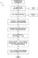
图18A至图18B,在此统称为图18,是示出用于光学轮廓测量系统的校准方法的一个示例的流程图。方法1200开始于框1205处,在此开始校准操作。通常,校准操作作为系统的正常制造过程1206的一部分被启动。校准操作也可以在某一时间量1207之后周期性地启动,或者校准方法可以基于其它因素,其它因素例如为系统使用1208或系统的环境条件1209方面的变化。所述操作可以由例如联接到光学轮廓测量系统的控制系统自动地开始,所述控制系统生成控制信号以启动校准方法。所述操作可以由例如在用户界面上生成某种形式的输入的用户或操作者手动开始,用户界面例如为显示屏、计算机、控制板、控制杆、开关或用于接收用户或操作者输入的任何其它合适的技术。可以基于阈值开始校准操作,所述阈值例如但不限于选择的(或以其它方式确定的)可接受值的范围。阈值可以是用户或操作者选择的、由制造商确定的、或由系统基于历史数据或基于被成像的目标的特性确定的、或用于确定阈值的任何其它合适的技术。校准方法可以基于时间间隔1209来启动,其中每当经过了一定量的时间时启动校准。或者,校准方法可以基于其它因素启动,其它因素例如但不限于效率、用户或操作者的期望、每当系统运行时的强制性等。18A-18B, collectively referred to herein as FIG. 18, are flowcharts illustrating one example of a calibration method for an optical profilometry system. The
方法1200在框1215处继续,在框1215处,全视场镜像测试目标被放置在系统的视场中心处、被安装在能够将测试目标定位在已知的z高度处和已知的表面梯度角(顶锥角)的运动系统上。在框1215处,测试目标最初被置于系统的最大正z高度和最大正表面的梯度角范围处。方法1200在框1225处继续,在框1225处镜像测试目标被移动到系统的表面梯度角范围的负极限。方法1200在框1235处继续,在框1235处镜像测试目标被移动到系统的z高度范围的负极限。The
方法1200在框1245处继续,在框1245处生成镜像测试目标的高度图像。方法1200在框1255处继续,在框1255处计算所生成的高度图像与镜像测试目标在系统的视场中的每个x、y位置处已知的z位置和表面梯度角的差值。The
方法1200在框1260处继续,在框1260处确定系统的全z高度范围是否已被采样。如果系统的全z高度范围未被采样,则方法1200在框1266继续。在框1266处,运动系统沿正z高度方向递增,并且采集目标的下一个图像(框1245)。一旦在沿z高度方向的整个范围内采集了图像,方法1200就继续到框1267处,在框1267处确定系统的整个表面梯度范围是否已经被采样。如果系统的整个表面梯度范围未被采样,则方法1200在框1265处继续,在框1265处运动系统沿正表面的梯度角范围的方向递增。The
如果在框1260处确定已经采样了全z范围,则方法1200在框1270处继续,在框1270处使用所采集的高度图像与镜像测试目标在每个x、y位置处的已知的z位置和表面梯度之间的差值来计算描述在每个x、y、z处的误差和表面梯度的最佳拟合函数p。If it is determined at
方法1200在框1280处继续,在框1280处存储最佳拟合函数p。函数p可以存储在与特定轮廓测量系统相关联的存储器部件中,例如,联接到光学轮廓测量系统的存储器部件。The
出于说明而非限制的目的,图18以特定顺序描绘了方法1200。可以设想方法1200的步骤的顺序可以改变,而不影响方法1200的目的。例如,在框1215处,测试目标可以在最大负范围处或在任何其它已知位置处开始,并且在框1225处,测试目标可以沿任何方向移动到任何已知的位置(例如,朝向负范围或正范围)。顺序不是决定性的,为了方法1200的目的,测试目标仅需要移动到系统的整个正范围和负范围内已知的位置。类似地,在框1265和1266处,可以设想,运动系统可沿负方向或沿负方向和正方向的组合移动。顺序不是决定性的。为了这种方法的目的,测试目标必须在系统的整个正范围和负范围内移动。For purposes of illustration and not limitation, FIG. 18 depicts
图19是示出使用校准偏移量生成对应于镜像目标的图像的方法的一个示例的流程图。方法1300在框1305处开始,在框1305处启动镜像测试目标的高度图像创建。方法1300在框1310处继续,在框1310处一组图案化照射被投射到镜像测试目标上。在框1310处的照射可以由本文所述的照射源1311中的任何一个来投射。方法1300在框1315处继续,在框1315处采集一组图案化照射的图像。这样的图像可以由本文描述的成像系统1316中的任何一个来采集。19 is a flowchart illustrating one example of a method of generating an image corresponding to a mirror target using a calibration offset. The
方法1300在框1320处继续,在框1320处使用所采集的一组图案化照射的图像来计算镜像测试目标的初始高度图像。方法1300在框1325处继续,在框1325处初始高度图像被分区成由表面反射率限定的子区域,以创建分区的高度图像。方法1300在框1330处继续,在框1330处在分区的高度图像中确定用于每个子区域的x、y位置。The
方法1300在框1335处继续,在框1335处使用校准函数p(如上所述),基于x、y位置、表面梯度和每个子区域的测量高度来计算用于每个子区域的高度校正偏移量。方法1300在框1340处继续,在框1340处,对于每个子区域,每个子区域的高度校正偏移量和初始高度计算最终的校正的高度图像。The
图20是示出根据本发明的实施例的光学轮廓测量系统的一个示例的简化框图。系统1400包括照射源1402、成像系统1404、电子装置1450、对准几何结构1462、电源1464、用户接口1468和远程装置1468。20 is a simplified block diagram illustrating one example of an optical profilometry system according to an embodiment of the present invention. System 1400 includes illumination source 1402 , imaging system 1404 , electronics 1450 , alignment geometry 1462 , power supply 1464 ,
照射源1402包括照射生成器1412、空间光调制器1413、透镜组件1414、孔径1416、壳体1418、电源1420和其它部件1422。照射源1402可以包括本文描述的任何实施例,包括单个照射源和多个照射源系统。照射生成器被配置成生成待投射到目标上的照射(例如,结构或图案化照射)。照射生成器可以包括结构光生成器、数字光处理(DLP)器、透射液晶、硅上液晶(LCOS)或用于投射结构式光图案的任何其它合适的技术。空间光调制器1413可以包括数字微镜装置。Illumination source 1402 includes
透镜组件1414被配置成将来自照射源1402的照射朝向目标引导,并且可以包括远心透镜组件、入射透镜和出射透镜、两个或更多透镜,以及由各种材料制成的透镜,所述材料包括但不限于聚碳酸酯、塑料、聚合物、玻璃、液体透镜材料,以及任何其它合适的材料。孔径1416被配置成引导来自照射源1402的照射,并可包括比成像系统1404的数值孔径大的数值孔径、比成像系统1404的数值孔径小的数值孔径或与成像系统1404的数值孔径相等的数值孔径。
壳体1418被配置成限定照射源1402的主体并且容纳照射源1402的部件。壳体1418可以包括任何数量的材料,材料包括但不限于塑料、聚合物、金属或任何其它合适的材料。壳体1418可包括本文所述的任何实施例,例如图14A和14B中所示的那些实施例。其它部件1422可包括适于由照射源用来将结构式照射投射到目标上的任何其它部件。Housing 1418 is configured to define the body of illumination source 1402 and to house the components of illumination source 1402 . Housing 1418 may comprise any number of materials including, but not limited to, plastic, polymer, metal, or any other suitable material. Housing 1418 may include any of the embodiments described herein, such as those shown in Figures 14A and 14B. Other components 1422 may include any other components suitable for use by the illumination source to project structured illumination onto the target.
成像系统1404包括透镜组件1428、孔径1430、相机1432、图像平面1434、分束器1436、调节机构1440、壳体1442、传感器1446和其它部件1448。成像源1404被配置成接收从照射源1402投射的从目标反射的照射。透镜组件1428被配置成将从目标反射的照射朝向成像系统的内部部件(例如,相机1432、图像平面1434和分束器1436)引导,并且可以包括远心透镜组件、入射透镜和出射透镜、两个或更多透镜、可调透镜以及由各种材料制成的透镜,所述材料包括但不限于聚碳酸酯、塑料、聚合物、玻璃、液体透镜材料以及任何其它合适的材料。孔径1430被配置成将从目标反射的照射朝向成像系统1404的内部部件引导,并且可以包括比照射源1402的数值孔径大的数值孔径、比照射源1402的数值孔径小的数值孔径或者与照射源1402的数值孔径相等的数值孔径。Imaging system 1404 includes
相机1432被配置成接收由照射源1402投射并从目标朝向成像系统1404反射的照射。相机1432可包括传感器1446,传感器被配置成基于所接收到的照射来生成指示目标的图像的传感器信号。图像平面1434是相机1432的一部分,并且限定了相机的表面,反射的照射在其穿过成像系统1404的内部部件(例如透镜组件1428、孔径1430、分束器1436)之后聚焦在所述表面上。分束器1436被配置成接收反射的照射并将反射光线束分成两个或更多光线束,例如,如图16中描述的分束器(例如1042)。Camera 1432 is configured to receive illumination projected by illumination source 1402 and reflected from the target toward imaging system 1404 . Camera 1432 may include a sensor 1446 configured to generate a sensor signal indicative of an image of the target based on the received illumination. Image plane 1434 is part of camera 1432 and defines the surface of the camera on which reflected illumination is focused after it passes through the internal components of imaging system 1404 (eg,
调节机构1440是被配置为改变透镜组件1428或成像系统1404的另一个部件的位置或特性的装置。调节机构1440可以包括机械装置,机械装置被配置成改变透镜的位置,使得透镜的焦点被改变(例如1138)。调节机构1440可以包括电光透镜,电光透镜在图像采集之间改变图像的形状,使得图像的聚焦位置改变。在这种系统中,通过施加电流来调节透镜的曲率。调节机构1440可以包括可变倍率透镜,例如液体透镜组件。调节机构可以包括被配置为改变图像平面1434的位置的装置。调节机构可以包括被配置成改变相机1432的位置的装置。调节机构1440可以包括任何其它合适的装置或技术,使得成像系统的聚焦位置可以改变。
壳体1442被配置为限定成像系统1404的主体并且容纳成像系统1404的部件。壳体1442可包括任何数量的材料,材料包括但不限于塑料、聚合物、金属或任何其它合适的材料。壳体1442可包括本文所述的任何实施例,例如图14A和14B中所示的那些实施例。传感器1446可以包括任何数量的传感器,传感器被配置为生成指示所接收的照射、目标尺寸信息、采集的图像等的特性的信号。其它部件1448可包括配置成允许成像系统1404接收照射或获得关于目标的尺寸信息的任何其它合适的部件,例如,其它部件1448可包括例如在最后一个透镜之后的某一点处插入成像系统1404的光学路径中的玻璃板,从而调节成像系统1404的聚焦位置。Housing 1442 is configured to define the body of imaging system 1404 and house the components of imaging system 1404 . Housing 1442 may comprise any number of materials including, but not limited to, plastic, polymer, metal, or any other suitable material. Housing 1442 may include any of the embodiments described herein, such as those shown in Figures 14A and 14B. Sensors 1446 may include any number of sensors configured to generate signals indicative of characteristics of the illumination received, target size information, acquired images, and the like. Other components 1448 may include any other suitable components configured to allow imaging system 1404 to receive illumination or obtain dimensional information about a target, for example, other components 1448 may include optics that are inserted into imaging system 1404, eg, at some point after the last lens glass plate in the path, thereby adjusting the focus position of the imaging system 1404.
电子装置150包括通信电路1452、处理器1454、控制器1456和其它部件1460。通信电路1452被配置成与系统1400的其它部件(例如,成像系统1404和照射源1402)以及外部部件(例如,用户接口1466、远程装置1468和显示器1470)通信。处理器1454被配置成接收信号和相对于目标的其它输入,并且基于那些信号和输入来确定和计算相对于目标的特性(例如,高度、斜度、x、y位置等)。例如,这样的处理器可以经由硬件、软件或二者的组合被适配用于从成像系统1404接收所采集的图像并且计算初始高度图像、将高度图像分区成子区域、确定每个子区域的x、y位置、确定每个子区域的表面梯度、计算高度校正,以及计算经校正的高度图像,如图19中所描述的。类似地,处理器1456被配置成计算和求解本文所描述的公式。
控制器1456被配置成从处理器1454和其它部件(例如,用户接口1466)接收信号并且生成控制信号以控制系统1400的部件。例如,控制器1456可以从处理器1454接收指示需要启动校准过程的输出。如图17中所描述的,控制器1456然后可生成控制信号以使成像系统1404采集镜像测试目标的图像。类似地,如图17中所描述的,控制器1456可生成控制信号以使通信电路1452将由处理器1454计算的校正函数P的描述存储在存储器1465中。另外,控制器1454可从用户接口1466接收指示控制系统1400的部件的需要的输入,并且生成控制信号以使例如调节机构1440改变透镜组件1428的位置或特性。另外,控制器1456可以基于一些接收的输入,例如来自处理器1454的系统1400需要校准的输入,来生成控制信号以使显示器1470显示关于系统1400的信息。在这样的示例中,控制器1456可以生成控制信号以发出可听警报或打开指示系统1400的状态的可见状态灯。
对准几何结构1462是系统1400的位置和对准结构。对准几何结构1462可以包括照射源1402或成像系统1404的竖直或水平位置,几何结构1462可以包括照射源1402或成像系统1404的方位角或光学轴线。几何结构1462可以包括本文所述的任何系统、方法、技术或实施例,例如,图13至图14B中所述的对准几何结构。Alignment geometry 1462 is the position and alignment structure of system 1400 . Alignment geometry 1462 may include the vertical or horizontal position of illumination source 1402 or imaging system 1404 , and geometry 1462 may include the azimuth or optical axis of illumination source 1402 or imaging system 1404 . Geometry 1462 may include any of the systems, methods, techniques, or embodiments described herein, eg, the alignment geometries described in Figures 13-14B.
电源1464被配置成向系统1400的部件提供电力。电源1464可包括电池、或与电路的有线连接或任何其它合适的技术,使得系统1400的部件将被供电。另外,系统1400的单独子系统(例如,照射源1402、成像系统1404和电子装置1450)中的每一个可包括它们自己的电源(例如,电池或到电子电路的单独连接),使得它们彼此独立地被供电。电源1464还可以包括这些部件的任何组合。Power supply 1464 is configured to provide power to the components of system 1400 . The power source 1464 may include a battery, or a wired connection to an electrical circuit, or any other suitable technology, such that the components of the system 1400 will be powered. Additionally, each of the individual subsystems of system 1400 (eg, illumination source 1402, imaging system 1404, and electronics 1450) may each include their own power source (eg, batteries or separate connections to electronic circuitry), making them independent of each other ground is powered. Power supply 1464 may also include any combination of these components.
存储器1465被配置成存储数据(例如,关于目标的尺寸信息、计算、确定、指令等)和校准信息,例如上文所描述的校正函数p()。存储器1465可包括RAM、ROM、高速缓存、动态RAM、静态RAM、闪存、虚拟存储器、视频存储器、BIOS或任何其它合适形式的存储器。存储器1465优选地电联接到系统1400。Memory 1465 is configured to store data (eg, dimensional information about the target, calculations, determinations, instructions, etc.) and calibration information, such as the correction function p( ) described above. Memory 1465 may include RAM, ROM, cache, dynamic RAM, static RAM, flash memory, virtual memory, video memory, BIOS, or any other suitable form of memory. Memory 1465 is preferably electrically coupled to system 1400.
用户接口1466被配置成接收用户或操作者输入,例如输入到控制系统1400的输入。用户接口可以包括触摸屏显示器、开关、控制杆、电子控制板、按钮、控制板或用于接收用户或操作者输入的任何其它合适的技术。远程装置1468可以包括电联接到但远离系统1400的装置,诸如有线环路上的控制室中的计算机。远程装置1468还可以包括无线联接到系统1400的装置,诸如手持式装置、膝上型计算机、平板计算机、场外计算机。远程装置可以被配置为显示、接收和发送关于系统1400的信息(例如,关于目标的尺寸信息、性能分析、警报和通知等)。显示器1470被配置为显示关于系统1400的信息。显示器1470可以包括可视显示器,例如屏幕显示器,或者被配置为显示系统1400的状态的灯(例如报警灯)。显示器1470可以包括被配置为生成噪声以传达关于系统1400的信息(例如,警报)的可听显示器。User interface 1466 is configured to receive user or operator input, such as input to control system 1400 . The user interface may include a touch screen display, switches, joysticks, electronic control pads, buttons, control pads, or any other suitable technology for receiving user or operator input.
虽然上面已经描述了系统1400,但是可以设想,这里描述的任何和所有系统、方法、技术和实施例都可以并入系统1400中。Although system 1400 has been described above, it is contemplated that any and all systems, methods, techniques, and embodiments described herein may be incorporated into system 1400 .
图21是示出根据本发明的实施例的光学轮廓测量系统的一个示例的示意图。系统1500包括照射源1502、成像系统1504、镜像目标1506、照射1508、照射主光线1509、反射1510、反射主光线1511、法向矢量1520、反射角1521和入射角1522。照射源1502包括光生成器1512(例如结构式光生成器)、空间光调制器1513(例如数字微镜装置)、透镜1514、孔径1516和透镜1518。照射源1502可以包括数字光处理(DLP)器、透射液晶、硅上液晶(LCOS)和用于投射结构式光图案的任何其它合适的技术。成像系统1504包括透镜1528、孔径1530、透镜1532、相机1534和图像平面1536。系统1500包括远心透镜系统。FIG. 21 is a schematic diagram showing one example of an optical profile measurement system according to an embodiment of the present invention. System 1500 includes
除了照射源和成像系统的数值孔径是相等的之外,系统1500类似于本文中描述的先前实施例。利用相等的数值孔径,如前所述,由于镜像反射引起的高度误差在孔径之间被平衡,从而将镜像反射测量误差最小化。虽然系统1500被说明性地示出为仅具有一个相机,但是可以设想,系统1500可以包括多个相机。另外,系统1500可包含分束器,以及本文描述的任何调节机构、调节技术、可调节透镜组件或可调节光学装置。System 1500 is similar to the previous embodiments described herein, except that the numerical apertures of the illumination source and imaging system are equal. With equal numerical apertures, height errors due to mirror reflections are balanced across apertures, as previously described, minimizing mirror reflection measurement errors. Although system 1500 is illustratively shown as having only one camera, it is contemplated that system 1500 may include multiple cameras. Additionally, system 1500 may include a beam splitter, as well as any of the adjustment mechanisms, adjustment techniques, adjustable lens assemblies, or adjustable optics described herein.
尽管已经参照优选实施例描述了本发明,但是本领域技术人员将认识到,在不脱离本发明的精神和范围的情况下,可以在形式和细节上进行改变。此外,虽然已经利用光学相位轮廓测量系统总体上描述了本发明的实施例,但是本文描述的技术、方法和系统可以利用任何数量的光学轮廓测量仪和其它光学成像系统来实现。Although the present invention has been described with reference to preferred embodiments, workers skilled in the art will recognize that changes may be made in form and detail without departing from the spirit and scope of the invention. Furthermore, although embodiments of the invention have been generally described using optical phase profilometry systems, the techniques, methods and systems described herein may be implemented using any number of optical profilometers and other optical imaging systems.
Claims (19)
Applications Claiming Priority (3)
| Application Number | Priority Date | Filing Date | Title |
|---|---|---|---|
| US201862621317P | 2018-01-24 | 2018-01-24 | |
| US62/621,317 | 2018-01-24 | ||
| PCT/US2019/014976WO2019147829A2 (en) | 2018-01-24 | 2019-01-24 | Structured light projection for specular surfaces |
Publications (2)
| Publication Number | Publication Date |
|---|---|
| CN111656779A CN111656779A (en) | 2020-09-11 |
| CN111656779Btrue CN111656779B (en) | 2022-10-18 |
Family
ID=67298108
Family Applications (2)
| Application Number | Title | Priority Date | Filing Date |
|---|---|---|---|
| CN201980009842.4AActiveCN111656779B (en) | 2018-01-24 | 2019-01-24 | Structured light projection for mirrored surfaces |
| CN201980009894.1AActiveCN111656260B (en) | 2018-01-24 | 2019-01-24 | Structured light projection for mirrored surfaces |
Family Applications After (1)
| Application Number | Title | Priority Date | Filing Date |
|---|---|---|---|
| CN201980009894.1AActiveCN111656260B (en) | 2018-01-24 | 2019-01-24 | Structured light projection for mirrored surfaces |
Country Status (6)
| Country | Link |
|---|---|
| US (2) | US11421983B2 (en) |
| EP (3) | EP4113993A1 (en) |
| KR (3) | KR102461481B1 (en) |
| CN (2) | CN111656779B (en) |
| SG (2) | SG11202006860UA (en) |
| WO (2) | WO2019147834A1 (en) |
Families Citing this family (8)
| Publication number | Priority date | Publication date | Assignee | Title |
|---|---|---|---|---|
| US11184967B2 (en) | 2018-05-07 | 2021-11-23 | Zane Coleman | Angularly varying light emitting device with an imager |
| US10816939B1 (en)* | 2018-05-07 | 2020-10-27 | Zane Coleman | Method of illuminating an environment using an angularly varying light emitting device and an imager |
| JP2020021105A (en)* | 2018-07-30 | 2020-02-06 | キヤノン株式会社 | Image processing apparatus, image processing method and program |
| US10883823B2 (en) | 2018-10-18 | 2021-01-05 | Cyberoptics Corporation | Three-dimensional sensor with counterposed channels |
| US11328380B2 (en)* | 2018-10-27 | 2022-05-10 | Gilbert Pinter | Machine vision systems, illumination sources for use in machine vision systems, and components for use in the illumination sources |
| US20230055268A1 (en)* | 2021-08-18 | 2023-02-23 | Meta Platforms Technologies, Llc | Binary-encoded illumination for corneal glint detection |
| US20230334681A1 (en)* | 2022-04-13 | 2023-10-19 | Hiroaki Kuwabara | Shape-data acquisition apparatus |
| US20240377334A1 (en)* | 2023-05-09 | 2024-11-14 | Applied Materials, Inc. | Automated optical inspection tool |
Citations (5)
| Publication number | Priority date | Publication date | Assignee | Title |
|---|---|---|---|---|
| CN101118155A (en)* | 2006-08-01 | 2008-02-06 | 三菱电机株式会社 | Method and system for sensing surface shape of a reflective object |
| CN101738728A (en)* | 2008-11-04 | 2010-06-16 | 株式会社三丰 | Optical aberration correction for machine vision inspection systems |
| CN101813460A (en)* | 2009-02-24 | 2010-08-25 | 康宁股份有限公司 | The shape measure of specular reflection surface |
| CN104729429A (en)* | 2015-03-05 | 2015-06-24 | 深圳大学 | Calibration method of telecentric imaging three-dimension topography measuring system |
| CN107607040A (en)* | 2017-08-11 | 2018-01-19 | 天津大学 | A kind of three-dimensional scanning measurement device and method suitable for High Reflective Surface |
Family Cites Families (66)
| Publication number | Priority date | Publication date | Assignee | Title |
|---|---|---|---|---|
| JP2751435B2 (en)* | 1989-07-17 | 1998-05-18 | 松下電器産業株式会社 | Inspection method for soldering condition of electronic components |
| US5917940A (en) | 1996-01-23 | 1999-06-29 | Nec Corporation | Three dimensional reference image segmenting method and device and object discrimination system |
| US6011624A (en)* | 1998-01-06 | 2000-01-04 | Zygo Corporation | Geometrically-Desensitized interferometer with adjustable range of measurement depths |
| KR100729290B1 (en)* | 2000-01-07 | 2007-06-25 | 사이버옵틱스 코포레이션 | Phase shape measurement system with telecentric projector |
| DE10163351C1 (en)* | 2001-12-14 | 2003-06-26 | Heimann Biometric Systems Gmbh | Method and arrangement for the low-distortion recording of intensity patterns created on a contact surface by disturbed total reflection |
| US7440590B1 (en)* | 2002-05-21 | 2008-10-21 | University Of Kentucky Research Foundation | System and technique for retrieving depth information about a surface by projecting a composite image of modulated light patterns |
| US6925860B1 (en)* | 2003-02-21 | 2005-08-09 | Nanometrics Incorporated | Leveling a measured height profile |
| JP2005300395A (en)* | 2004-04-14 | 2005-10-27 | Toppan Printing Co Ltd | Foreign matter and defect inspection equipment |
| US7002737B1 (en)* | 2004-08-31 | 2006-02-21 | Yokogawa Electric Corp. | Three-dimensional confocal microscope |
| US7522289B2 (en)* | 2004-10-13 | 2009-04-21 | Solvision, Inc. | System and method for height profile measurement of reflecting objects |
| US7436524B2 (en)* | 2004-11-26 | 2008-10-14 | Olympus Corporation | Apparatus and method for three-dimensional measurement and program for allowing computer to execute method for three-dimensional measurement |
| CN101431611A (en)* | 2004-11-30 | 2009-05-13 | 松下电器产业株式会社 | Image processing method, image processing apparatus, image processing program, and image file format |
| US20070023716A1 (en) | 2005-07-26 | 2007-02-01 | Icos Vision Systems N.V. | Apparatus for three dimensional measuring on an electronic component |
| JP4600763B2 (en) | 2005-09-20 | 2010-12-15 | 横河電機株式会社 | Orientation meter |
| DE102006016131A1 (en) | 2005-09-22 | 2007-03-29 | Robert Bosch Gmbh | Interferometric measuring device |
| US7408649B2 (en)* | 2005-10-26 | 2008-08-05 | Kla-Tencor Technologies Corporation | Method and apparatus for optically analyzing a surface |
| US7724942B2 (en)* | 2005-10-31 | 2010-05-25 | Mitutoyo Corporation | Optical aberration correction for machine vision inspection systems |
| US7256596B1 (en)* | 2005-11-01 | 2007-08-14 | Russell Robert J | Method and apparatus for adapting a standard flying prober system for reliable testing of printed circuit assemblies |
| CN1945204A (en)* | 2006-10-19 | 2007-04-11 | 上海大学 | Three dimension outline measuring device and method for mirror article surface |
| DE102007002106B3 (en)* | 2007-01-09 | 2008-07-03 | Wolfgang Weinhold | Object's surface configuration examining device, has control and evaluation unit connected with light sources and light sensor, where light sources are arranged such that optical radiation axis runs in different reference planes |
| WO2008124397A1 (en)* | 2007-04-03 | 2008-10-16 | David Fishbaine | Inspection system and method |
| CN101821659B (en)* | 2007-10-11 | 2014-09-24 | 3M创新有限公司 | Chromatic confocal sensor |
| US8047753B2 (en) | 2008-07-22 | 2011-11-01 | The Boeing Company | Insulating washers |
| US8432395B2 (en)* | 2009-06-16 | 2013-04-30 | Apple Inc. | Method and apparatus for surface contour mapping |
| CA2683206C (en)* | 2009-10-17 | 2018-07-03 | Hermary Opto Electronics Inc. | Enhanced imaging method and apparatus |
| AU2010336460B2 (en)* | 2009-12-23 | 2013-06-13 | Colgate-Palmolive Company | Visually patterned and oriented compositions |
| US8134719B2 (en) | 2010-03-19 | 2012-03-13 | Carestream Health, Inc. | 3-D imaging using telecentric defocus |
| US8437517B2 (en) | 2010-11-03 | 2013-05-07 | Lockheed Martin Corporation | Latent fingerprint detectors and fingerprint scanners therefrom |
| JP2014516409A (en)* | 2011-04-15 | 2014-07-10 | ファロ テクノロジーズ インコーポレーテッド | Improved position detector for laser trackers. |
| US20120287198A1 (en)* | 2011-05-11 | 2012-11-15 | Fujifilm Dimatix, Inc. | Imaging Jetted Ink |
| CN102564348A (en)* | 2012-01-03 | 2012-07-11 | 四川大学 | Systematic geometric demarcation method for reflection three-dimensional measurement of stripe |
| FI125320B (en)* | 2012-01-05 | 2015-08-31 | Helmee Imaging Oy | EVENTS AND SIMILAR OPTICAL MEASUREMENT PROCEDURES |
| CN102721378B (en)* | 2012-06-20 | 2015-04-29 | 北京航空航天大学 | Three-dimensional mirror object shape measurement system based on sinusoidal stripe projection |
| JP6029394B2 (en)* | 2012-09-11 | 2016-11-24 | 株式会社キーエンス | Shape measuring device |
| JP6112807B2 (en) | 2012-09-11 | 2017-04-12 | 株式会社キーエンス | Shape measuring device, shape measuring method, and shape measuring program |
| JP6091866B2 (en) | 2012-11-30 | 2017-03-08 | 株式会社キーエンス | Measurement microscope apparatus, image generation method, measurement microscope apparatus operation program, and computer-readable recording medium |
| US20140198185A1 (en)* | 2013-01-17 | 2014-07-17 | Cyberoptics Corporation | Multi-camera sensor for three-dimensional imaging of a circuit board |
| CN104111036A (en)* | 2013-04-18 | 2014-10-22 | 中国科学院沈阳自动化研究所 | Mirror object measuring device and method based on binocular vision |
| US10126252B2 (en) | 2013-04-29 | 2018-11-13 | Cyberoptics Corporation | Enhanced illumination control for three-dimensional imaging |
| CN103217873A (en)* | 2013-05-06 | 2013-07-24 | 中国科学院光电技术研究所 | Focus detection device based on double-grating moire fringes |
| JP6173156B2 (en) | 2013-10-02 | 2017-08-02 | キヤノン株式会社 | Image processing apparatus, imaging apparatus, and image processing method |
| JP6184289B2 (en)* | 2013-10-17 | 2017-08-23 | 株式会社キーエンス | 3D image processing apparatus, 3D image processing method, 3D image processing program, computer-readable recording medium, and recorded apparatus |
| US9726876B2 (en) | 2013-11-27 | 2017-08-08 | Mitutoyo Corporation | Machine vision inspection system and method for obtaining an image with an extended depth of field |
| KR102214296B1 (en)* | 2014-01-09 | 2021-02-08 | 지고 코포레이션 | Measuring topography of aspheric and other non-flat surfaces |
| WO2015175702A1 (en)* | 2014-05-14 | 2015-11-19 | Kla-Tencor Corporation | Image acquisition system, image acquisition method, and inspection system |
| US10419703B2 (en)* | 2014-06-20 | 2019-09-17 | Qualcomm Incorporated | Automatic multiple depth cameras synchronization using time sharing |
| CN104181777B (en)* | 2014-07-31 | 2016-03-09 | 中国科学院微电子研究所 | Focusing and leveling sensor measuring device |
| US9675430B2 (en)* | 2014-08-15 | 2017-06-13 | Align Technology, Inc. | Confocal imaging apparatus with curved focal surface |
| EP3194939B1 (en) | 2014-09-11 | 2021-11-03 | Cyberoptics Corporation | Point cloud merging from multiple cameras and sources in three-dimensional profilometry |
| TWM502849U (en)* | 2015-01-12 | 2015-06-11 | Hauman Technologies Corp | Equipment capable of automatically tuning point measurement position according to images of object under test and probe tip |
| DE102015209404B4 (en) | 2015-05-22 | 2018-05-03 | Sirona Dental Systems Gmbh | Method and camera for three-dimensional measurement of a dental object |
| KR101639227B1 (en)* | 2015-06-08 | 2016-07-13 | 주식회사 고영테크놀러지 | Three dimensional shape measurment apparatus |
| US10495446B2 (en)* | 2015-06-29 | 2019-12-03 | Kla-Tencor Corporation | Methods and apparatus for measuring height on a semiconductor wafer |
| CN105372803A (en) | 2015-09-06 | 2016-03-02 | 长春迪瑞医疗科技股份有限公司 | Depth of field-increasing microscopic optical system |
| US10176588B2 (en) | 2015-09-14 | 2019-01-08 | Sightline Innovation Inc. | System and method for specular surface inspection |
| US10412365B2 (en)* | 2015-09-22 | 2019-09-10 | Purdue Research Foundation | Calibration arrangement for structured light system using a tele-centric lens |
| US9924115B2 (en)* | 2015-09-23 | 2018-03-20 | Agilent Technologies, Inc. | Apparatus and method for three-dimensional infrared imaging of surfaces |
| KR102368597B1 (en)* | 2015-11-11 | 2022-03-02 | 삼성전자주식회사 | Image photographing apparatus and method of controlling thereof |
| US9958259B2 (en)* | 2016-01-12 | 2018-05-01 | Canon Kabushiki Kaisha | Depth value measurement |
| JP6692660B2 (en)* | 2016-03-01 | 2020-05-13 | 株式会社Screenホールディングス | Imaging device |
| US20170268990A1 (en) | 2016-03-17 | 2017-09-21 | Canon Kabushiki Kaisha | Separating diffuse and specular components of a glossy object for shape reconstruction using electronic light diffusing layers (e-glass) and polarized light |
| US20180180883A1 (en) | 2016-12-23 | 2018-06-28 | Raja Singh Tuli | Augmented reality eyewear |
| JP6829993B2 (en)* | 2016-12-28 | 2021-02-17 | 株式会社キーエンス | Optical scanning height measuring device |
| US10768404B2 (en) | 2017-03-22 | 2020-09-08 | Mitutoyo Corporation | Modulation monitoring system for use with an imaging system that includes a high speed periodically modulated variable focal length lens |
| EP3396306B1 (en) | 2017-04-26 | 2019-11-27 | Mitutoyo Corporation | Method and system for calculating a height map of a surface of an object from an image stack in scanning optical 2.5d profiling of the surface by an optical system |
| US10410510B2 (en) | 2017-05-01 | 2019-09-10 | Federal Signal Corporation | Hazardous detection call point stations |
- 2019
- 2019-01-24CNCN201980009842.4Apatent/CN111656779B/enactiveActive
- 2019-01-24WOPCT/US2019/014981patent/WO2019147834A1/ennot_activeCeased
- 2019-01-24CNCN201980009894.1Apatent/CN111656260B/enactiveActive
- 2019-01-24KRKR1020207023706Apatent/KR102461481B1/enactiveActive
- 2019-01-24USUS16/256,460patent/US11421983B2/enactiveActive
- 2019-01-24WOPCT/US2019/014976patent/WO2019147829A2/ennot_activeCeased
- 2019-01-24EPEP22181520.2Apatent/EP4113993A1/enactivePending
- 2019-01-24SGSG11202006860UApatent/SG11202006860UA/enunknown
- 2019-01-24SGSG11202006968PApatent/SG11202006968PA/enunknown
- 2019-01-24USUS16/256,579patent/US11073380B2/enactiveActive
- 2019-01-24EPEP19744481.3Apatent/EP3743763A4/enactivePending
- 2019-01-24KRKR1020227031500Apatent/KR102597197B1/enactiveActive
- 2019-01-24KRKR1020207022992Apatent/KR102328240B1/enactiveActive
- 2019-01-24EPEP19743536.5Apatent/EP3744089A4/enactivePending
Patent Citations (5)
| Publication number | Priority date | Publication date | Assignee | Title |
|---|---|---|---|---|
| CN101118155A (en)* | 2006-08-01 | 2008-02-06 | 三菱电机株式会社 | Method and system for sensing surface shape of a reflective object |
| CN101738728A (en)* | 2008-11-04 | 2010-06-16 | 株式会社三丰 | Optical aberration correction for machine vision inspection systems |
| CN101813460A (en)* | 2009-02-24 | 2010-08-25 | 康宁股份有限公司 | The shape measure of specular reflection surface |
| CN104729429A (en)* | 2015-03-05 | 2015-06-24 | 深圳大学 | Calibration method of telecentric imaging three-dimension topography measuring system |
| CN107607040A (en)* | 2017-08-11 | 2018-01-19 | 天津大学 | A kind of three-dimensional scanning measurement device and method suitable for High Reflective Surface |
Also Published As
| Publication number | Publication date |
|---|---|
| SG11202006860UA (en) | 2020-08-28 |
| WO2019147834A1 (en) | 2019-08-01 |
| KR20200109360A (en) | 2020-09-22 |
| EP3743763A4 (en) | 2021-12-08 |
| KR102597197B1 (en) | 2023-11-01 |
| SG11202006968PA (en) | 2020-08-28 |
| US20190226835A1 (en) | 2019-07-25 |
| KR102461481B1 (en) | 2022-10-31 |
| EP4113993A1 (en) | 2023-01-04 |
| US11421983B2 (en) | 2022-08-23 |
| KR20220128453A (en) | 2022-09-20 |
| WO2019147829A2 (en) | 2019-08-01 |
| KR20200108874A (en) | 2020-09-21 |
| EP3744089A4 (en) | 2021-10-20 |
| CN111656260B (en) | 2022-11-25 |
| EP3743763A1 (en) | 2020-12-02 |
| WO2019147829A3 (en) | 2019-09-19 |
| EP3744089A2 (en) | 2020-12-02 |
| US11073380B2 (en) | 2021-07-27 |
| CN111656260A (en) | 2020-09-11 |
| CN111656779A (en) | 2020-09-11 |
| US20190226836A1 (en) | 2019-07-25 |
| KR102328240B1 (en) | 2021-11-17 |
Similar Documents
| Publication | Publication Date | Title |
|---|---|---|
| CN111656779B (en) | Structured light projection for mirrored surfaces | |
| JP7640661B2 (en) | Three-dimensional sensor having oppositely arranged channels - Patents.com | |
| JPH1183438A (en) | Position calibration method for optical measuring device | |
| US7941913B2 (en) | Component placement unit as well as a component placement device comprising such a component placement unit | |
| RU2635336C2 (en) | Method of calibrating optical-electronic device and device for its implementation | |
| Wang et al. | Easy and flexible calibration approach for deflectometry-based vr eye-tracking systems | |
| TWI582400B (en) | Detection target plate, optical detection device and optical detection method |
Legal Events
| Date | Code | Title | Description |
|---|---|---|---|
| PB01 | Publication | ||
| PB01 | Publication | ||
| SE01 | Entry into force of request for substantive examination | ||
| SE01 | Entry into force of request for substantive examination | ||
| GR01 | Patent grant | ||
| GR01 | Patent grant |