CN111656217B - System and method for virtual aperture radar tracking - Google Patents
System and method for virtual aperture radar trackingDownload PDFInfo
- Publication number
- CN111656217B CN111656217BCN201880088097.2ACN201880088097ACN111656217BCN 111656217 BCN111656217 BCN 111656217BCN 201880088097 ACN201880088097 ACN 201880088097ACN 111656217 BCN111656217 BCN 111656217B
- Authority
- CN
- China
- Prior art keywords
- signal
- target
- radar
- array
- phase
- Prior art date
- Legal status (The legal status is an assumption and is not a legal conclusion. Google has not performed a legal analysis and makes no representation as to the accuracy of the status listed.)
- Active
Links
Images


Classifications
- G—PHYSICS
- G01—MEASURING; TESTING
- G01S—RADIO DIRECTION-FINDING; RADIO NAVIGATION; DETERMINING DISTANCE OR VELOCITY BY USE OF RADIO WAVES; LOCATING OR PRESENCE-DETECTING BY USE OF THE REFLECTION OR RERADIATION OF RADIO WAVES; ANALOGOUS ARRANGEMENTS USING OTHER WAVES
- G01S13/00—Systems using the reflection or reradiation of radio waves, e.g. radar systems; Analogous systems using reflection or reradiation of waves whose nature or wavelength is irrelevant or unspecified
- G01S13/003—Bistatic radar systems; Multistatic radar systems
- G—PHYSICS
- G01—MEASURING; TESTING
- G01S—RADIO DIRECTION-FINDING; RADIO NAVIGATION; DETERMINING DISTANCE OR VELOCITY BY USE OF RADIO WAVES; LOCATING OR PRESENCE-DETECTING BY USE OF THE REFLECTION OR RERADIATION OF RADIO WAVES; ANALOGOUS ARRANGEMENTS USING OTHER WAVES
- G01S13/00—Systems using the reflection or reradiation of radio waves, e.g. radar systems; Analogous systems using reflection or reradiation of waves whose nature or wavelength is irrelevant or unspecified
- G01S13/66—Radar-tracking systems; Analogous systems
- G01S13/72—Radar-tracking systems; Analogous systems for two-dimensional tracking, e.g. combination of angle and range tracking, track-while-scan radar
- G01S13/723—Radar-tracking systems; Analogous systems for two-dimensional tracking, e.g. combination of angle and range tracking, track-while-scan radar by using numerical data
- G—PHYSICS
- G01—MEASURING; TESTING
- G01S—RADIO DIRECTION-FINDING; RADIO NAVIGATION; DETERMINING DISTANCE OR VELOCITY BY USE OF RADIO WAVES; LOCATING OR PRESENCE-DETECTING BY USE OF THE REFLECTION OR RERADIATION OF RADIO WAVES; ANALOGOUS ARRANGEMENTS USING OTHER WAVES
- G01S13/00—Systems using the reflection or reradiation of radio waves, e.g. radar systems; Analogous systems using reflection or reradiation of waves whose nature or wavelength is irrelevant or unspecified
- G01S13/88—Radar or analogous systems specially adapted for specific applications
- G01S13/89—Radar or analogous systems specially adapted for specific applications for mapping or imaging
- G01S13/90—Radar or analogous systems specially adapted for specific applications for mapping or imaging using synthetic aperture techniques, e.g. synthetic aperture radar [SAR] techniques
- G—PHYSICS
- G01—MEASURING; TESTING
- G01S—RADIO DIRECTION-FINDING; RADIO NAVIGATION; DETERMINING DISTANCE OR VELOCITY BY USE OF RADIO WAVES; LOCATING OR PRESENCE-DETECTING BY USE OF THE REFLECTION OR RERADIATION OF RADIO WAVES; ANALOGOUS ARRANGEMENTS USING OTHER WAVES
- G01S13/00—Systems using the reflection or reradiation of radio waves, e.g. radar systems; Analogous systems using reflection or reradiation of waves whose nature or wavelength is irrelevant or unspecified
- G01S13/88—Radar or analogous systems specially adapted for specific applications
- G01S13/93—Radar or analogous systems specially adapted for specific applications for anti-collision purposes
- G01S13/933—Radar or analogous systems specially adapted for specific applications for anti-collision purposes of aircraft or spacecraft
- G01S13/934—Radar or analogous systems specially adapted for specific applications for anti-collision purposes of aircraft or spacecraft on airport surfaces, e.g. while taxiing
- G—PHYSICS
- G01—MEASURING; TESTING
- G01S—RADIO DIRECTION-FINDING; RADIO NAVIGATION; DETERMINING DISTANCE OR VELOCITY BY USE OF RADIO WAVES; LOCATING OR PRESENCE-DETECTING BY USE OF THE REFLECTION OR RERADIATION OF RADIO WAVES; ANALOGOUS ARRANGEMENTS USING OTHER WAVES
- G01S7/00—Details of systems according to groups G01S13/00, G01S15/00, G01S17/00
- G01S7/02—Details of systems according to groups G01S13/00, G01S15/00, G01S17/00 of systems according to group G01S13/00
- G01S7/42—Diversity systems specially adapted for radar
- G—PHYSICS
- G01—MEASURING; TESTING
- G01S—RADIO DIRECTION-FINDING; RADIO NAVIGATION; DETERMINING DISTANCE OR VELOCITY BY USE OF RADIO WAVES; LOCATING OR PRESENCE-DETECTING BY USE OF THE REFLECTION OR RERADIATION OF RADIO WAVES; ANALOGOUS ARRANGEMENTS USING OTHER WAVES
- G01S13/00—Systems using the reflection or reradiation of radio waves, e.g. radar systems; Analogous systems using reflection or reradiation of waves whose nature or wavelength is irrelevant or unspecified
- G01S13/02—Systems using reflection of radio waves, e.g. primary radar systems; Analogous systems
- G01S13/06—Systems determining position data of a target
- G01S13/42—Simultaneous measurement of distance and other co-ordinates
- G01S13/44—Monopulse radar, i.e. simultaneous lobing
- G01S13/4463—Monopulse radar, i.e. simultaneous lobing using phased arrays
- G—PHYSICS
- G01—MEASURING; TESTING
- G01S—RADIO DIRECTION-FINDING; RADIO NAVIGATION; DETERMINING DISTANCE OR VELOCITY BY USE OF RADIO WAVES; LOCATING OR PRESENCE-DETECTING BY USE OF THE REFLECTION OR RERADIATION OF RADIO WAVES; ANALOGOUS ARRANGEMENTS USING OTHER WAVES
- G01S13/00—Systems using the reflection or reradiation of radio waves, e.g. radar systems; Analogous systems using reflection or reradiation of waves whose nature or wavelength is irrelevant or unspecified
- G01S13/66—Radar-tracking systems; Analogous systems
- G—PHYSICS
- G01—MEASURING; TESTING
- G01S—RADIO DIRECTION-FINDING; RADIO NAVIGATION; DETERMINING DISTANCE OR VELOCITY BY USE OF RADIO WAVES; LOCATING OR PRESENCE-DETECTING BY USE OF THE REFLECTION OR RERADIATION OF RADIO WAVES; ANALOGOUS ARRANGEMENTS USING OTHER WAVES
- G01S13/00—Systems using the reflection or reradiation of radio waves, e.g. radar systems; Analogous systems using reflection or reradiation of waves whose nature or wavelength is irrelevant or unspecified
- G01S13/86—Combinations of radar systems with non-radar systems, e.g. sonar, direction finder
- G—PHYSICS
- G01—MEASURING; TESTING
- G01S—RADIO DIRECTION-FINDING; RADIO NAVIGATION; DETERMINING DISTANCE OR VELOCITY BY USE OF RADIO WAVES; LOCATING OR PRESENCE-DETECTING BY USE OF THE REFLECTION OR RERADIATION OF RADIO WAVES; ANALOGOUS ARRANGEMENTS USING OTHER WAVES
- G01S13/00—Systems using the reflection or reradiation of radio waves, e.g. radar systems; Analogous systems using reflection or reradiation of waves whose nature or wavelength is irrelevant or unspecified
- G01S13/88—Radar or analogous systems specially adapted for specific applications
- G01S13/93—Radar or analogous systems specially adapted for specific applications for anti-collision purposes
- G01S13/931—Radar or analogous systems specially adapted for specific applications for anti-collision purposes of land vehicles
- G—PHYSICS
- G01—MEASURING; TESTING
- G01S—RADIO DIRECTION-FINDING; RADIO NAVIGATION; DETERMINING DISTANCE OR VELOCITY BY USE OF RADIO WAVES; LOCATING OR PRESENCE-DETECTING BY USE OF THE REFLECTION OR RERADIATION OF RADIO WAVES; ANALOGOUS ARRANGEMENTS USING OTHER WAVES
- G01S15/00—Systems using the reflection or reradiation of acoustic waves, e.g. sonar systems
- G01S15/66—Sonar tracking systems
- G—PHYSICS
- G01—MEASURING; TESTING
- G01S—RADIO DIRECTION-FINDING; RADIO NAVIGATION; DETERMINING DISTANCE OR VELOCITY BY USE OF RADIO WAVES; LOCATING OR PRESENCE-DETECTING BY USE OF THE REFLECTION OR RERADIATION OF RADIO WAVES; ANALOGOUS ARRANGEMENTS USING OTHER WAVES
- G01S13/00—Systems using the reflection or reradiation of radio waves, e.g. radar systems; Analogous systems using reflection or reradiation of waves whose nature or wavelength is irrelevant or unspecified
- G01S13/02—Systems using reflection of radio waves, e.g. primary radar systems; Analogous systems
- G01S2013/0236—Special technical features
- G01S2013/0245—Radar with phased array antenna
- G01S2013/0263—Passive array antenna
- G—PHYSICS
- G01—MEASURING; TESTING
- G01S—RADIO DIRECTION-FINDING; RADIO NAVIGATION; DETERMINING DISTANCE OR VELOCITY BY USE OF RADIO WAVES; LOCATING OR PRESENCE-DETECTING BY USE OF THE REFLECTION OR RERADIATION OF RADIO WAVES; ANALOGOUS ARRANGEMENTS USING OTHER WAVES
- G01S13/00—Systems using the reflection or reradiation of radio waves, e.g. radar systems; Analogous systems using reflection or reradiation of waves whose nature or wavelength is irrelevant or unspecified
- G01S13/88—Radar or analogous systems specially adapted for specific applications
- G01S13/93—Radar or analogous systems specially adapted for specific applications for anti-collision purposes
- G01S13/931—Radar or analogous systems specially adapted for specific applications for anti-collision purposes of land vehicles
- G01S2013/9316—Radar or analogous systems specially adapted for specific applications for anti-collision purposes of land vehicles combined with communication equipment with other vehicles or with base stations
- G—PHYSICS
- G01—MEASURING; TESTING
- G01S—RADIO DIRECTION-FINDING; RADIO NAVIGATION; DETERMINING DISTANCE OR VELOCITY BY USE OF RADIO WAVES; LOCATING OR PRESENCE-DETECTING BY USE OF THE REFLECTION OR RERADIATION OF RADIO WAVES; ANALOGOUS ARRANGEMENTS USING OTHER WAVES
- G01S13/00—Systems using the reflection or reradiation of radio waves, e.g. radar systems; Analogous systems using reflection or reradiation of waves whose nature or wavelength is irrelevant or unspecified
- G01S13/88—Radar or analogous systems specially adapted for specific applications
- G01S13/93—Radar or analogous systems specially adapted for specific applications for anti-collision purposes
- G01S13/931—Radar or analogous systems specially adapted for specific applications for anti-collision purposes of land vehicles
- G01S2013/932—Radar or analogous systems specially adapted for specific applications for anti-collision purposes of land vehicles using own vehicle data, e.g. ground speed, steering wheel direction
- G—PHYSICS
- G01—MEASURING; TESTING
- G01S—RADIO DIRECTION-FINDING; RADIO NAVIGATION; DETERMINING DISTANCE OR VELOCITY BY USE OF RADIO WAVES; LOCATING OR PRESENCE-DETECTING BY USE OF THE REFLECTION OR RERADIATION OF RADIO WAVES; ANALOGOUS ARRANGEMENTS USING OTHER WAVES
- G01S13/00—Systems using the reflection or reradiation of radio waves, e.g. radar systems; Analogous systems using reflection or reradiation of waves whose nature or wavelength is irrelevant or unspecified
- G01S13/88—Radar or analogous systems specially adapted for specific applications
- G01S13/93—Radar or analogous systems specially adapted for specific applications for anti-collision purposes
- G01S13/931—Radar or analogous systems specially adapted for specific applications for anti-collision purposes of land vehicles
- G01S2013/9322—Radar or analogous systems specially adapted for specific applications for anti-collision purposes of land vehicles using additional data, e.g. driver condition, road state or weather data
- G—PHYSICS
- G01—MEASURING; TESTING
- G01S—RADIO DIRECTION-FINDING; RADIO NAVIGATION; DETERMINING DISTANCE OR VELOCITY BY USE OF RADIO WAVES; LOCATING OR PRESENCE-DETECTING BY USE OF THE REFLECTION OR RERADIATION OF RADIO WAVES; ANALOGOUS ARRANGEMENTS USING OTHER WAVES
- G01S13/00—Systems using the reflection or reradiation of radio waves, e.g. radar systems; Analogous systems using reflection or reradiation of waves whose nature or wavelength is irrelevant or unspecified
- G01S13/88—Radar or analogous systems specially adapted for specific applications
- G01S13/93—Radar or analogous systems specially adapted for specific applications for anti-collision purposes
- G01S13/931—Radar or analogous systems specially adapted for specific applications for anti-collision purposes of land vehicles
- G01S2013/9323—Alternative operation using light waves
- G—PHYSICS
- G01—MEASURING; TESTING
- G01S—RADIO DIRECTION-FINDING; RADIO NAVIGATION; DETERMINING DISTANCE OR VELOCITY BY USE OF RADIO WAVES; LOCATING OR PRESENCE-DETECTING BY USE OF THE REFLECTION OR RERADIATION OF RADIO WAVES; ANALOGOUS ARRANGEMENTS USING OTHER WAVES
- G01S13/00—Systems using the reflection or reradiation of radio waves, e.g. radar systems; Analogous systems using reflection or reradiation of waves whose nature or wavelength is irrelevant or unspecified
- G01S13/88—Radar or analogous systems specially adapted for specific applications
- G01S13/93—Radar or analogous systems specially adapted for specific applications for anti-collision purposes
- G01S13/931—Radar or analogous systems specially adapted for specific applications for anti-collision purposes of land vehicles
- G01S2013/9324—Alternative operation using ultrasonic waves
- G—PHYSICS
- G01—MEASURING; TESTING
- G01S—RADIO DIRECTION-FINDING; RADIO NAVIGATION; DETERMINING DISTANCE OR VELOCITY BY USE OF RADIO WAVES; LOCATING OR PRESENCE-DETECTING BY USE OF THE REFLECTION OR RERADIATION OF RADIO WAVES; ANALOGOUS ARRANGEMENTS USING OTHER WAVES
- G01S7/00—Details of systems according to groups G01S13/00, G01S15/00, G01S17/00
- G01S7/52—Details of systems according to groups G01S13/00, G01S15/00, G01S17/00 of systems according to group G01S15/00
- G01S7/52017—Details of systems according to groups G01S13/00, G01S15/00, G01S17/00 of systems according to group G01S15/00 particularly adapted to short-range imaging
- G01S7/52019—Details of transmitters
- G—PHYSICS
- G01—MEASURING; TESTING
- G01S—RADIO DIRECTION-FINDING; RADIO NAVIGATION; DETERMINING DISTANCE OR VELOCITY BY USE OF RADIO WAVES; LOCATING OR PRESENCE-DETECTING BY USE OF THE REFLECTION OR RERADIATION OF RADIO WAVES; ANALOGOUS ARRANGEMENTS USING OTHER WAVES
- G01S7/00—Details of systems according to groups G01S13/00, G01S15/00, G01S17/00
- G01S7/52—Details of systems according to groups G01S13/00, G01S15/00, G01S17/00 of systems according to group G01S15/00
- G01S7/52017—Details of systems according to groups G01S13/00, G01S15/00, G01S17/00 of systems according to group G01S15/00 particularly adapted to short-range imaging
- G01S7/52023—Details of receivers
Landscapes
- Engineering & Computer Science (AREA)
- Remote Sensing (AREA)
- Radar, Positioning & Navigation (AREA)
- Physics & Mathematics (AREA)
- Computer Networks & Wireless Communication (AREA)
- General Physics & Mathematics (AREA)
- Electromagnetism (AREA)
- Aviation & Aerospace Engineering (AREA)
- Radar Systems Or Details Thereof (AREA)
Abstract
Description
Translated fromChinese技术领域technical field
本发明总体上涉及雷达领域,并且更具体地涉及用于虚拟孔径雷达跟踪的新的且有用的系统和方法。The present invention relates generally to the field of radars, and more particularly to new and useful systems and methods for virtual aperture radar tracking.
背景background
传统的基于阵列的接收器通过使用波束成形(例如,数字波束成形)测量在阵列(如图1所示(1D阵列))内不同接收器(或天线)处接收的探测信号之间的时间或相位差来计算方位角和/或仰角(elevation)。使用发射阵列而不是接收阵列可以产生类似的效果。这些传统解决方案是受限制的:角度分辨率取决于阵列中元件的数量以及阵列与目标之间的角度:Conventional array-based receivers measure the time or Phase difference to calculate azimuth and/or elevation. Using a transmit array instead of a receive array can have a similar effect. These traditional solutions are limited: the angular resolution depends on the number of elements in the array and the angle between the array and the target:

其中,N是阵列中的元件的个数,以及d是它们之间间隔的距离。where N is the number of elements in the array, and d is the distance between them.
因此,在雷达领域中需要创建用于虚拟孔径雷达跟踪的新的且有用的系统和方法。本发明提供了这种新且有用的系统和方法。Therefore, there is a need in the radar field to create new and useful systems and methods for virtual aperture radar tracking. The present invention provides such new and useful systems and methods.
附图简述Brief description of the drawings
图1是1D接收器阵列雷达系统的现有技术示例图;Figure 1 is a prior art illustration of a 1D receiver array radar system;
图2是发明实施例的方法的图表视图(chart view);Fig. 2 is a chart view (chart view) of the method of the invention embodiment;
图3A是在SAR跟踪中物理孔径的示例视图;Figure 3A is an example view of a physical aperture in SAR tracking;
图3B是在SAR跟踪中虚拟孔径的示例视图;Figure 3B is an example view of a virtual aperture in SAR tracking;
图4A是在VAA跟踪中第一物理孔径的示例视图;Figure 4A is an example view of a first physical aperture in VAA tracking;
图4B是在VAA跟踪中第二物理孔径的示例视图;Figure 4B is an example view of a second physical aperture in VAA tracking;
图4C是在VAA跟踪中虚拟孔径的示例视图;Figure 4C is an example view of a virtual aperture in VAA tracking;
图5A是入射在传统接收器阵列上的信号的示意视图;Figure 5A is a schematic view of a signal incident on a conventional receiver array;
图5B是入射在传统接收器阵列上的信号的信号视图;Figure 5B is a signal view of a signal incident on a conventional receiver array;
图6A是入射在VAA系统上的信号的示意视图;Figure 6A is a schematic view of a signal incident on a VAA system;
图6B是入射在VAA系统上的信号的信号视图;Figure 6B is a signal view of a signal incident on a VAA system;
图7是间隔一定距离的两个发射器元件的相移的示例视图;Figure 7 is an example view of the phase shift of two transmitter elements separated by a distance;
图8是在VAA系统中虚拟发射器元件和接收器元件的示意视图;Figure 8 is a schematic view of virtual transmitter elements and receiver elements in a VAA system;
图9是目标位置参数的笛卡尔坐标系视图;Fig. 9 is the Cartesian coordinate system view of target position parameter;
图10是发明实施例的系统的示意视图;以及Figure 10 is a schematic view of a system of an embodiment of the invention; and
图11是发明实施例的系统的示意视图。Figure 11 is a schematic view of a system of an embodiment of the invention.
发明实施例的描述Description of Embodiments of the Invention
本发明的发明实施例的以下描述并非旨在将本发明限制于这些发明实施例,而是旨在使本领域的任何技术人员能够制造并且使用本发明。The following description of the inventive embodiments of the present invention is not intended to limit the invention to these inventive embodiments, but is intended to enable any person skilled in the art to make and use the invention.
1.用于虚拟孔径阵列雷达跟踪的方法1. Method for Virtual Aperture Array Radar Tracking
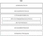
用于虚拟孔径阵列(VAA)雷达跟踪的方法100包括:发射一组探测信号S110,接收一组反射探测信号S120,以及根据该一组反射探测信号计算初始跟踪参数S130,如图2所示。方法100可以另外包括细化初始跟踪参数S140和/或修改探测信号特性S150。The
如背景部分中所讨论的,传统的基于阵列的雷达系统是受限制的:角度分辨率取决于接收器阵列中的元件的数量以及阵列和目标之间的角度:As discussed in the background section, traditional array-based radar systems are limited: the angular resolution depends on the number of elements in the receiver array and the angle between the array and the target:

其中,N是阵列中的元件的数量,以及d是它们之间间隔的距离。where N is the number of elements in the array, and d is the distance between them.
这里,阵列元件的数量(以及它们之间间隔的距离)与接收器的孔径相关;也就是说,越多的元件(或增大的元件间距)导致接收器孔径增大。正如角度分辨率公式所表明的,(在不改变载波频率的情况下)要增大角度分辨率,必须增加接收器的孔径。通常,这是通过添加接收器阵列元件或增加元件之间的间隔距离来实现的;然而,这些技术增加了接收器阵列的物理尺寸或其成本和物理复杂性中的一者或两者。然而,这种传统技术的亮点在于,它提高了雷达分辨率,而在处理延时方面变化相对较小。Here, the number of array elements (and the distance between them) is related to the aperture of the receiver; that is, more elements (or increased element spacing) result in an increase in the aperture of the receiver. As the angular resolution formula shows, to increase angular resolution (without changing the carrier frequency), the aperture of the receiver must be increased. Typically, this is accomplished by adding receiver array elements or increasing the separation distance between elements; however, these techniques increase the physical size of the receiver array or one or both of its cost and physical complexity. However, the beauty of this traditional technique is that it increases radar resolution with relatively little change in processing latency.
作为这种传统技术的替代方案,创建了合成孔径雷达(SAR)。在SAR中,移动的天线(或天线阵列)在其移动时连续捕获多个信号,如图3A所示;这些信号然后被组合(利用天线运动的知识)来模拟更大的天线的效果,如图3B所示。SAR设法模拟增大的雷达孔径(从而提高雷达分辨率),但是需要精确的天线运动数据,并且通常需要在处理延时方面显著增加。这两个要求在许多应用中都是有问题的。As an alternative to this traditional technology, synthetic aperture radar (SAR) was created. In SAR, a moving antenna (or antenna array) acquires multiple signals in succession as it moves, as shown in Figure 3A; these signals are then combined (using knowledge of the antenna motion) to simulate the effect of a larger antenna, as Figure 3B. SAR manages to simulate an increased radar aperture (and thus radar resolution), but requires precise antenna motion data and often requires a significant increase in processing latency. Both of these requirements are problematic in many applications.
方法100利用新颖的技术来模拟增加的雷达孔径(如SAR所表现的那样),而不会招致增加物理阵列尺寸而增加的额外成本/尺寸或SAR的严重缺点(例如,运动数据要求和高处理延时)。这项技术被称为虚拟孔径阵列(VAA)雷达跟踪。注意,虽然术语“虚拟孔径”在雷达跟踪领域具有多种用途,但是如在本申请中所使用的,虚拟孔径阵列雷达跟踪具体指的是本文描述的跟踪技术(而不是共用该术语的任何不相关的技术)。
方法100的VAA雷达跟踪技术通过在物理阵列处同时捕获第一信号的实例(像传统的相控阵(phased array)一样),然后在同一物理阵列处捕获第二信号的实例(同时捕获第二信号的实例,但不必与捕获第一信号的实例同时捕获);如果适用,以相同的方式捕获另外的实例,且最后一起处理从所有捕获的实例接收的数据,以生成比其他方式更高分辨率的雷达跟踪解。值得注意的是,第一信号和第二信号(以及任何另外的信号)用不同的相位信息编码。该不同的相位信息使得第二信号的实例能够被视为是在从物理阵列移位的虚拟接收器阵列处被接收(创建比物理孔径更大的虚拟孔径)。例如,可以如图4A所示捕获具有第一相位编码的第一信号,并且可以如图4B所示捕获具有第二相位编码的第二信号;这些信号可以一起被处理,如图4C所示。The VAA radar tracking technique of
如图5A所示,当从与六个元件的雷达阵列成角度(即,不垂直于该六个元件的雷达阵列)的目标接收到反射信号时,在阵列中的每个接收器元件处接收到的信号相对于在阵列中的其他元件处接收到的信号发生相移,如图5B所示。根据元件之间的相移和间距,可以确定目标相对于阵列的角度。As shown in Figure 5A, when a reflected signal is received from a target at an angle to (i.e., not perpendicular to) the six-element radar array, at each receiver element in the array The received signal is phase shifted relative to the signal received at other elements in the array, as shown in Figure 5B. Based on the phase shift and spacing between elements, the angle of the target relative to the array can be determined.
如图6A所示,方法200可以通过使用两个相移信号仅用三个元件来模拟相同的孔径,产生如图6B所示的接收器元件处的信号(注意,在t2的RX1处的信号类似于图5B中RX4处的信号,依此类推)。“虚拟元件”的定位取决于第一信号和第二信号之间的相移。As shown in Figure 6A, the method 200 can simulate the same aperture with only three elements by using two phase-shifted signals, resulting in the signal at the receiver element as shown in Figure 6B (note that the signal at RX1 at t2 Similar to the signal at RX4 in Figure 5B, and so on). The positioning of the "virtual element" depends on the phase shift between the first signal and the second signal.
方法100优选地由用于VAA雷达跟踪的系统(例如,系统200)实现,但是可以另外地或替代性地使用能够执行虚拟孔径阵列目标跟踪的任何合适的目标跟踪系统(例如,声呐(SONAR)、激光雷达(LIDAR))来实现。
S110包括发射一组探测信号。S110用于发射一组信号,该一组信号在被目标反射后,可以提供关于目标的信息(例如,相对位置、速度等)。S110优选地包括:发射=频移键控(FSK)雷达信号或发射=频率修正连续波(FMCW)雷达信号,但是S110可以包括发射满足这些约束的任何信号;例如电磁信号(如以雷达中的无线电波,激光雷达中的红外/可见光/UV波的形式)、声音信号(如以声呐的形式)。S110 includes transmitting a set of detection signals. S110 is used to transmit a set of signals, which can provide information about the target (eg, relative position, speed, etc.) after being reflected by the target. S110 preferably includes: transmitting = Frequency Shift Keying (FSK) radar signal or transmitting = Frequency Modified Continuous Wave (FMCW) radar signal, but S110 may include transmitting any signal that satisfies these constraints; for example an electromagnetic signal (as in radar radio waves, in the form of infrared/visible/UV waves in lidar), sound signals (eg in the form of sonar).
S110优选地包括发射至少两个不同的探测信号。S110中的该一组探测信号优选地满足两个约束条件:该一组中的每一个在相位上是不同的(如从某个参考点测量),并且该一组中的每一个在接收时是彼此可区分的。相位上的区分能够有效地增加孔径(从而提高角度分辨率),而可区分性确保在接收时,鉴于在相位上的区分信号而使数据得到适当的处理。S110 preferably includes transmitting at least two different detection signals. The set of probe signals in S110 preferably satisfies two constraints: each of the set is different in phase (as measured from some reference point), and each of the set is different in phase when received are distinguishable from each other. Distinguishing in phase effectively increases the aperture (and thus angular resolution), while distinguishability ensures that, on reception, the data is properly processed in view of the discriminating signals in phase.
S110可以以若干种方式完成相位区分。例如,S110可以包括从物理上不同的天线元件发射探测信号。对于与发射器元件呈一定角度的目标,间隔对固有相位差进行编码(该固有相位差取决于角度!),如图7所示。对于间隔开一段距离dTX的两个发射器,目标与法线在θ下的相位差约为S110 Phase differentiation can be accomplished in several ways. For example, S110 may include transmitting probing signals from physically distinct antenna elements. For targets at an angle to the transmitter element, the separation encodes an inherent phase difference (which is angle dependent!), as shown in Figure 7. For two transmitters separated by a distance dTX , the phase difference between the target and the normal at θ is approximately

并且在接收器处看到的相位差大致相同。And the phase difference seen at the receiver is about the same.
作为第二示例,S110可以包括在不同时间从相同的天线元件发射探测信号,但是探测信号具有不同的相位信息。例如,S110可以包括在第一时间从天线元件发射第一信号,然后在第二时间从相同天线元件发射第二相移信号。注意,这不等同于第一示例中的相位差;在目标处看到的(第一信号和第二信号之间)相位差dφ是(近似)恒定的,并且与目标的角度无关。还要注意的是,虽然这种相位差异导致对增加的接收器元件的模拟,但它也导致对增加的发射器元件的模拟,如图8所示。As a second example, S110 may include transmitting sounding signals from the same antenna element at different times, but with different phase information. For example, S110 may include transmitting a first signal from an antenna element at a first time, and then transmitting a second phase-shifted signal from the same antenna element at a second time. Note that this is not equivalent to the phase difference in the first example; the phase difference dφ (between the first and second signal) seen at the target is (approximately) constant and independent of the angle of the target. Note also that while this phase difference results in the simulation of added receiver elements, it also results in the simulation of added transmitter elements, as shown in Figure 8.
其结果是,虽然相位差异是由天线元件间隔产生的,但对于所有目标角度而言,虚拟孔径的大小大致相同;在显式相移(explicit phase shifting)示例中,虚拟孔径的大小取决于目标角度。例如,在发射器间隔的情况下,阵列移位可以被写成As a result, the size of the virtual aperture is approximately the same for all target angles, although the phase difference is due to the antenna element spacing; in the case of explicit phase shifting, the size of the virtual aperture depends on the target angle. For example, in the case of emitter spacing, the array shift can be written as

而在显式相移的情况下while in the case of an explicit phase shift

其中dφ是恒定的(且因此d阵列取决于目标角度)。where dφ is constant (and thus the darray depends on the target angle).
虽然S110优选地利用移相器(即,相移理想地独立于频率的设备)来执行显式相移,但是S110可以另外地或替代性地利用延迟线(或相移依赖于频率的任何其他设备)和/或时间延迟和移相器的任何组合来执行显式相移。While S110 preferably utilizes a phase shifter (i.e., a device whose phase shift is ideally independent of frequency) to perform explicit phase shifting, S110 may additionally or alternatively utilize a delay line (or any other phase shift whose phase shift is frequency dependent). devices) and/or any combination of time delays and phase shifters to perform explicit phase shifting.
S110可以另外地或替代性地包括组合相移技术(例如,使用间隔一定距离的多个发射器,并且使发射器相对于彼此相移)。S110 may additionally or alternatively include combining phase shifting techniques (eg, using multiple transmitters spaced apart by a distance, and phase shifting the transmitters relative to each other).
注意,虽然给出了具有恒定时间的相移的示例,但是S110可以另外地或替代性地包括通过物理地移动发射器(即,给出dTX时间关系)和/或通过添加相位dφ来随时间调制相位,其中相位是时间的函数。发射信号随时间的相位称为相位函数。相位函数可以参考任何点。例如,如果第一天线元件和第二天线元件(间隔开非零距离(non-zero distance))分别产生相同的第一信号和第二信号,则可以说第一信号的相位函数(以第一发射器为基准)与第二信号的相位函数(以第二发射器为基准)相同。然而,这两个信号在被目标以相对于发射器阵列呈一定角度反射后的相位并不看起来与在目标处(或在接收器阵列处)相同。Note that although an example of a phase shift with constant time isgiven , S110 may additionally or alternatively include shifting Time modulated phase, where phase is a function of time. The phase of the transmitted signal over time is called the phase function. The phase function can refer to any point. For example, if a first antenna element and a second antenna element (separated by a non-zero distance (non-zero distance)) generate the same first and second signals, respectively, then it can be said that the phase function of the first signal (in the first transmitter referenced) is the same as the phase function of the second signal (referenced to the second transmitter). However, the phases of the two signals after being reflected by the target at an angle relative to the transmitter array do not appear to be the same at the target (or at the receiver array).
S110可以另外地或替代性地包括相对于角度调制相位(例如,通过使用可操纵的或可定向的天线和在扫描天线时调制相位,使用天线阵列和针对阵列的不同元件调制相位,等等)。S110 may additionally or alternatively include modulating the phase with respect to the angle (e.g., by using a steerable or steerable antenna and modulating the phase while scanning the antenna, using an antenna array and modulating the phase for different elements of the array, etc.) .
S110还可以以若干种方式中的任何一种来实现信号可区分性。如前所述,S110可以实现信号可区分性的一种方式是对信号进行时分双工(time-duplexing)(例如,发射具有第一相位编码的第一频率啁啾信号,然后发射具有第二相位编码的第二信号);然而,S110可以另外地或替代性地通过频分复用信号(例如,在第一频带内发射第一频率啁啾信号,并且在与第一频率啁啾信号不重叠的第二频带内发射第二频率啁啾信号),或者通过对信号进行编码(例如,使用不同的频率调制或幅度调制技术来将信号与其他信号区分开来),来使信号可区分。S110可以另外地或替代性地以任何方式实现信号可区分性。S110 may also implement signal distinguishability in any of several ways. As mentioned earlier, one way S110 can achieve signal distinguishability is by time-duplexing the signal (for example, transmitting a first frequency chirp signal with a first phase encoding, and then transmitting a chirp signal with a second phase encoding). phase-encoded second signal); however, S110 may additionally or alternatively transmit a first frequency chirp signal within a first frequency band by frequency division multiplexing (for example, transmitting a first frequency chirp signal within a first frequency band, and Transmitting a second frequency chirp signal in an overlapping second frequency band), or making the signal distinguishable by encoding the signal (eg, using a different frequency modulation or amplitude modulation technique to distinguish the signal from other signals). S110 may additionally or alternatively implement signal distinguishability in any manner.
S120包括接收一组反射的探测信号。S120用于接收由S110中发射的探测信号的反射产生的数据。S120优选地包括测量来自反射探测信号的相位、幅度、和频率信息,但是S120可以另外地或替代性地包括测量反射探测信号的任何可用特性。S120 includes receiving a set of reflected detection signals. S120 is configured to receive data generated by the reflection of the detection signal transmitted in S110. S120 preferably includes measuring phase, amplitude, and frequency information from the reflected probe signal, but S120 may additionally or alternatively include measuring any available characteristic of the reflected probe signal.
S120优选地包括测量用于恢复信号识别信息(即,用于确定反射探测信号对应于该发射组中的哪个信号的信息)所需的任何数据。S120 preferably includes measuring any data necessary for recovering signal identification information, ie information for determining to which signal in the transmit group the reflected probe signal corresponds.
S130包括根据该一组反射探测信号计算初始跟踪参数。S130用于计算至少识别目标相对于雷达接收器的位置的一组跟踪参数;另外地或替代性地,跟踪参数可以包括与对象跟踪相关的另外的参数(例如,目标速度、目标加速度)。注意,S130可以包括为给定目标计算比获得位置解所需的更多的跟踪参数;例如,如稍后所述,虽然只有距离、方位角、和仰角可能是计算目标位置所必需的,但是复合角度(composite angle)也可以被计算并被用于改进和/或检查方位角/仰角计算。S130 includes calculating initial tracking parameters according to the set of reflected detection signals. S130 is for calculating a set of tracking parameters that at least identify the position of the target relative to the radar receiver; additionally or alternatively, the tracking parameters may include additional parameters related to object tracking (eg target velocity, target acceleration). Note that S130 may include calculating more tracking parameters for a given target than are required to obtain a position solution; for example, as described later, while only range, azimuth, and elevation may be necessary to calculate the target position, but Composite angles can also be calculated and used to refine and/or check azimuth/elevation calculations.
此外,虽然S130主要包括根据反射探测信号计算跟踪参数,但S130可以另外地或替代性地计算或以其他方式接收不使用探测信号计算的与目标跟踪相关的参数(例如,雷达自运动速度)。In addition, although S130 mainly includes calculating tracking parameters based on reflected detection signals, S130 may additionally or alternatively calculate or otherwise receive parameters related to target tracking (eg, radar self-motion velocity) calculated without using detection signals.
用于建立目标位置的参数可以在任何坐标系和基础中定义。在本申请中,目标位置优选地在笛卡尔坐标系中被表示,其中原点在雷达处(例如,x,y,z表示目标位置),或者在球面坐标系中被表示,其中原点相同,其中位置由距离(R)、方位角(α)、和仰角(θ)定义;可替代地,可以以任何方式描述目标位置。注意,仰角(和类似地,方位角)是参考向量和投影目标向量之间的角度的示例;投影目标向量是观察者(例如,雷达)和目标之间的、投影到参考平面(包含参考向量的参考平面)中的向量。方法100可以包括计算任何这样的角度。The parameters used to establish the target position can be defined in any coordinate system and basis. In this application, the target position is preferably expressed in a Cartesian coordinate system, where the origin is at the radar (e.g., x, y, z denote the target position), or in a spherical coordinate system, where the origin is the same, where A location is defined by range (R), azimuth (α), and elevation (θ); alternatively, the target location may be described in any manner. Note that the elevation angle (and similarly, the azimuth angle) is an example of the angle between the reference vector and the projected target vector; the projected target vector is the angle between the observer (e.g., radar) and the target, projected onto the reference plane (containing the reference vector A vector in the reference plane).
尽管如前所述可以在S130中计算与目标跟踪相关的任何参数,但是可以计算的一些附加参数包括目标距离变化率(target range rate)(dR/dt,通常根据多普勒数据计算)、相对目标速度(目标相对于雷达接收器的速度)、雷达自运动速度(在本申请中称为自速度(egovelocity),雷达接收器相对于静止位置的速度)。这些可能是相关的;例如,距离变化率等于相对目标速度乘以雷达和目标之间视角的余弦。Although any parameter related to target tracking can be calculated in S130 as previously described, some additional parameters that can be calculated include target range rate (dR/dt, usually calculated from Doppler data), relative Target velocity (velocity of the target relative to the radar receiver), radar ego velocity (referred to in this application as egovelocity, the velocity of the radar receiver relative to the stationary position). These may be related; for example, the rate of change of range is equal to the relative target velocity multiplied by the cosine of the angle of view between the radar and target.
S130可以另外地或替代性地包括计算复合角度(β,目标和雷达之间的角度:β=arccos[cosα×cosθ],另外参见图9)。虽然复合角度可以从仰角和方位角导出(反之亦然),但也可以根据多普勒数据计算出。例如,如果根据第一数据源(例如,接收器阵列中的接收器之间的相位差)计算仰角和方位角,并且根据第二数据源(例如,多普勒频移和相对速度)计算复合角度,则复合角度可以与仰角和方位角一起使用,以产生更精确的解。S130 may additionally or alternatively include calculating a composite angle (β, the angle between the target and the radar: β=arccos[cosα×cosθ], see also FIG. 9 ). While composite angles can be derived from elevation and azimuth (and vice versa), they can also be calculated from Doppler data. For example, if elevation and azimuth are computed from a first source of data (e.g., phase difference between receivers in a receiver array), and the composite angle, compound angles can be used with elevation and azimuth angles to produce a more accurate solution.
S130可以包括根据任何合适的数据源计算跟踪参数。例如,在具有水平接收器阵列的雷达系统上操作,方位角可以基于由阵列中每个接收器看到的反射探测信号之间的相位差来计算出。同样,垂直接收器阵列可以以类似的方式计算仰角(和/或可以通过二维接收器阵列以类似的方式计算仰角和方位角)。例如,可以基于探测信号的传播时间计算出距离(range)。例如,可以瞬时(例如,使用多普勒频移数据)或随时间(例如,通过测量距离随时间的变化)计算距离变化率。如前所述,复合角可以从仰角/方位角中导出,或者明确地根据多普勒数据计算出:fD≈Kvcosβ;

另外地,S130可以包括以任何方式计算相对目标速度。例如,S130可以包括确定目标是静止的,并且基于自速度计算相对目标速度(即,在这种情况下,相对目标速度是自速度)。目标可以以任何方式被确定为是静止的;例如,通过在视觉上将目标识别为静止目标(例如,可以通过其外观来识别停止标志),通过其雷达截面将目标识别为静止目标(例如,可以通过形状或其他特征来识别停止标志或道路),通过将多普勒数据与其他(例如,相位)数据进行比较(例如,如果由多普勒数据提供的复合角度与从仰角和方位角导出的复合角度基本上不同,则其可能是移动目标),通过目标的大小或者以任何其他方式。同样,自速度可以以任何方式(例如,耦合到雷达接收器的位置的GPS接收器或IMU、外部跟踪系统等)确定。作为另一个示例,S130可以包括接收基于外部数据的相对目标速度信息;例如来自耦合到雷达接收器位置的视觉跟踪系统的估计。相对目标速度信息甚至可以由外部跟踪系统或目标本身提供(例如,从目标车辆传输IMU数据)。Additionally, S130 may include calculating the relative target speed in any manner. For example, S130 may include determining that the target is stationary, and calculating a relative target velocity based on the self velocity (ie, in this case, the relative target velocity is the self velocity). A target can be determined to be stationary in any manner; for example, by visually identifying the target as stationary (e.g., a stop sign can be identified by its appearance), by its radar cross-section (e.g., can identify stop signs or roads by shape or other features), by comparing the Doppler data with other (e.g., phase) data (e.g., if the composite angle provided by the Doppler data is the same as that derived from elevation and azimuth The composite angles are substantially different, then it may be a moving target), by the size of the target or in any other way. Likewise, self-velocity may be determined in any manner (eg, GPS receiver or IMU coupled to the location of the radar receiver, external tracking system, etc.). As another example, S130 may include receiving relative target velocity information based on external data; such as an estimate from a visual tracking system coupled to the position of the radar receiver. Relative target velocity information can even be provided by an external tracking system or the target itself (e.g., IMU data transmitted from the target vehicle).
为了确定多普勒频移,S130可以包括使用快速傅立叶变换将反射信号数据变换到频域(或者将时域信号变换到频域以用于分析的任何其他技术)。S130还可以通过使用滑动快速傅立叶变换(SFFT)或类似技术,例如滑动离散傅立叶变换(SDFT)和短时傅立叶变换(STFT),来提高系统性能。这些技术允许以显著更低的计算开销来计算样本流中连续样本的傅立叶变换,从而提高性能。To determine the Doppler shift, S130 may include transforming the reflected signal data into the frequency domain using a Fast Fourier Transform (or any other technique that transforms a time domain signal into the frequency domain for analysis). S130 can also improve system performance by using sliding fast Fourier transform (SFFT) or similar techniques, such as sliding discrete Fourier transform (SDFT) and short-time Fourier transform (STFT). These techniques allow computing the Fourier transform of successive samples in a stream of samples with significantly lower computational overhead, improving performance.
S130优选地包括通过将信号实例链接到接收器元件S131并在接收器元件上执行波束成形S132来根据两个或更多个反射探测信号计算初始跟踪参数。S130 preferably includes computing initial tracking parameters from the two or more reflected probe signals by linking signal instances to receiver elements S131 and performing beamforming S132 on the receiver elements.
S131包括将信号实例链接到接收器元件。S131用于将在给定接收器元件处接收的信号实例对应于真实或虚拟接收器元件。例如,对第一(零相位)信号和第二(相移)信号进行时间双工的雷达系统可以将在物理接收器元件处接收的信号实例对应于该接收器元件(如果反射信号是第一信号)或移位的虚拟接收器元件(如果反射信号是第二信号)。注意,虽然在一些情况下虚拟接收器元件的平移(translation)与目标角度无关,但是在虚拟接收器元件的平移取决于目标角度的情况下,可能需要在联合使用所有接收信号之前独立地首先使用一个或更多个接收信号子集(每个子集对应于唯一发射信号之一)初步确定目标角度(以便知道虚拟接收器元件的位置)。换句话说,虚拟元件可以通过元件平移函数(element translation function)按照物理元件来描述;如果该平移函数尚未知(如在间隔的发射器的情况下),则S131可以包括确定给定目标的元件平移函数。S131 includes linking signal instances to receiver elements. S131 is for the signal instance to be received at a given receiver element to correspond to a real or virtual receiver element. For example, a radar system that time-duplexes a first (zero-phase) signal and a second (phase-shifted) signal can assign the signal instance received at a physical receiver element to that receiver element (if the reflected signal is the first signal) or a displaced virtual receiver element (if the reflected signal is the second signal). Note that while in some cases the translation of the virtual receiver element is independent of the target angle, in cases where the translation of the virtual receiver element is dependent on the target angle, it may be necessary to first use One or more subsets of received signals (each subset corresponding to one of the unique transmitted signals) initially determine the target angle (so that the position of the virtual receiver element is known). In other words, virtual elements can be described in terms of physical elements by an element translation function; if this translation function is not yet known (as in the case of spaced emitters), then S131 can include determining the element of a given target translation function.
S132包括在接收器元件上执行波束成形。一旦数据已经链接到真实或虚拟接收器元件位置,S132使用波束成形技术来计算对象跟踪数据(例如,目标距离(target range)和角度)。S132可以使用的波束成形技术包括但不限于常规(即,Bartlett)波束成形、最小方差无失真响应(MVDR,也称为Capon)波束成形、多信号分类(MUSIC)波束成形、或任何其他波束成形技术。S132 includes performing beamforming on the receiver elements. Once the data has been linked to real or virtual receiver element positions, S132 uses beamforming techniques to compute object tracking data (eg target range and angle). Beamforming techniques that S132 may use include, but are not limited to, conventional (i.e., Bartlett) beamforming, Minimum Variance Distortionless Response (MVDR, also known as Capon) beamforming, Multiple Signal Classification (MUSIC) beamforming, or any other beamforming technology.
S132优选地包括使用阵列中的每个元件(真实的和虚拟的)对给定的目标跟踪元件阵列执行数字波束成形,但是S132可以另外地或替代性地使用元件的任何子集来执行角度计算。在一些实施例中,S132可以包括动态选择用于执行数字波束成形技术的接收器元件(例如,基于接收器噪声或任何其他相关因素)。S132 preferably includes performing digital beamforming on a given array of target tracking elements using each element in the array (real and virtual), but S132 may additionally or alternatively use any subset of elements to perform angle calculations . In some embodiments, S132 may include dynamically selecting receiver elements for performing digital beamforming techniques (eg, based on receiver noise or any other relevant factors).
S140包括细化初始跟踪参数。S140用于产生比S130最初计算的更精确的跟踪解。在第一示例实现方式中,S140包括对由(根据相位信息确定的)仰角或方位角、距离、和受复合角度的误差界限约束的复合角度产生的目标的笛卡尔坐标运行卡尔曼滤波器(Kalmanfilter)。在第二示例实现方式中,S140包括对目标的笛卡尔坐标运行卡尔曼滤波器,该目标的笛卡尔坐标是由(根据相位信息确定的)仰角和方位角、距离、和受复合角度的误差界限约束的复合角度产生的。S140 includes refining the initial tracking parameters. S140 is used to generate a more accurate tracking solution than originally calculated at S130. In a first example implementation, S140 includes running a Kalman filter on the Cartesian coordinates of the target resulting from the elevation or azimuth angle (determined from the phase information), distance, and compound angle constrained by an error bound for the compound angle ( Kalman filter). In a second example implementation, S140 includes running a Kalman filter on the Cartesian coordinates of the target, which are determined by (determined from the phase information) elevation and azimuth angles, range, and the error compounded by the angle Composite angles generated by bounds constraints.
S140可以另外地或替代性地包括以任何方式过滤、细化、和/或约束跟踪参数。S140 may additionally or alternatively include filtering, refining, and/or constraining tracking parameters in any manner.
S150包括修改探测信号特性。S150用于修改发射的探测信号的特性,以确保雷达跟踪算法的高性能。方法100的优点之一是可以随意添加(以及扩展虚拟孔径)或去除虚拟发射器/接收器元件。添加更多虚拟元件增加了方法100执行的对象跟踪的潜在准确性,但是也增加了对象跟踪的延时。S150 includes modifying a probe signal characteristic. S150 is used to modify the characteristics of the transmitted detection signal to ensure the high performance of the radar tracking algorithm. One of the advantages of
S150可以包括基于S130的输出来修改探测信号特性;例如,如果在对象跟踪期间检测到第一组数据(例如,对应于较早发射的信号和真实接收器)和第二组数据(对应于较晚发射的信号和虚拟接收器)未能在某个阈值误差范围内收敛于对象跟踪解,S150可以包括修改发射的信号以减少虚拟元件的数量(例如,将不同的相位编码信号的数量从三个减少到两个)。S150 may include modifying the probe signal characteristics based on the output of S130; for example, if a first set of data (e.g., corresponding to earlier transmitted signals and true receivers) and a second set of data (corresponding to earlier Late transmitted signals and virtual receivers) fail to converge on the object tracking solution within a certain threshold error, S150 may include modifying the transmitted signals to reduce the number of virtual elements (for example, reducing the number of different phase-encoded signals from three reduced to two).
可替代地,S150可以包括基于其他数据修改探测信号特性。例如,S150可以包括基于雷达阵列运动(例如,车载雷达的汽车速度)修改探测信号数据;当汽车移动得更慢时修改发射(transmission)以增加虚拟孔径,以及当汽车移动得更快时修改发射以减少虚拟孔径。Alternatively, S150 may include modifying the probe signal characteristic based on other data. For example, S150 may include modifying the detection signal data based on radar array motion (e.g., car speed from on-board radar); modifying transmission when the car is moving slower to increase the virtual aperture, and modifying transmission when the car is moving faster to reduce the virtual aperture.
S150可以另外地或替代性地包括(在发射器或接收器处)以任何方式修改探测信号特性。S150 may additionally or alternatively include modifying the probe signal characteristics (at the transmitter or receiver) in any manner.
2.用于虚拟孔径阵列雷达跟踪的系统2. System for Virtual Aperture Array Radar Tracking
如图10所示,用于虚拟孔径阵列(VAA)雷达跟踪的系统200包括发射器210、水平接收器阵列220、和信号处理器240。系统200可以另外地包括垂直接收器阵列230和/或速度感测模块250。As shown in FIG. 10 , a system 200 for virtual aperture array (VAA) radar tracking includes a
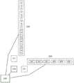
此外,系统200可以包括任意数量的虚拟发射器211和/或虚拟接收器元件222/232,如图11所示。Additionally, the system 200 may include any number of virtual transmitters 211 and/or
类似于方法100,系统200利用VAA雷达跟踪来模拟增加的雷达孔径(如SAR所表现的那样),而不会招致增加物理阵列尺寸的额外成本/尺寸或SAR的严重缺点(例如,运动数据要求和高处理延时)。Similar to
系统200的VAA雷达跟踪技术通过在物理阵列处同时捕获第一信号的实例(像传统的相控阵一样),然后在同一物理阵列处捕获第二信号的实例(同时捕获第二信号的实例,但不必与捕获第一信号的实例同时捕获);如果适用,以相同的方式捕获另外的实例,且最后一起处理从所有捕获的实例接收的数据,以生成比其他方式更高分辨率的雷达跟踪解。值得注意的是,第一信号和第二信号(以及任何另外的信号)用不同的相位信息编码。该不同的相位信息使得第二信号的实例能够被视为在相对于物理阵列移位的虚拟接收器阵列处被接收(创建比物理孔径大的虚拟孔径)。例如,可以如图4A所示捕获具有第一相位编码的第一信号,并且可以如图4B所示捕获具有第二相位编码的第二信号;这些信号可以一起处理,如图4C所示。The VAA radar tracking technique of system 200 works by simultaneously capturing an instance of a first signal at a physical array (like a conventional phased array), and then capturing an instance of a second signal at the same physical array (simultaneously capturing an instance of the second signal, but not necessarily at the same time as the instance that captured the first signal); if applicable, additional instances are captured in the same manner, and finally the data received from all captured instances are processed together to generate a higher resolution radar track than would otherwise be possible untie. Notably, the first signal and the second signal (and any further signals) are encoded with different phase information. This different phase information enables instances of the second signal to be seen as being received at a virtual receiver array that is displaced relative to the physical array (creating a virtual aperture that is larger than the physical aperture). For example, a first signal with a first phase encoding may be captured as shown in FIG. 4A, and a second signal with a second phase encoding may be captured as shown in FIG. 4B; these signals may be processed together, as shown in FIG. 4C.
发射器210用于发射信号,该信号在被目标反射后,可以提供关于目标的信息(例如,相对位置、速度等)。发射器210优选地发射频移键控(FSK)雷达信号或频率修正连续波(FMCW)雷达信号,但是发射器210可以发射满足这些约束的任何信号;例如电磁信号(如以雷达中的无线电波,激光雷达中的红外/可见光/UV波的形式)、声音信号(如以声呐的形式)。The
发射器210优选地具有单个发射元件(例如,单个发射天线),但是可以另外地或替代性地(例如,如在雷达阵列中)具有多个发射元件。如果发射器210具有多个元件,则这些元件可以包括与多个天线配对的单个发射器(例如,以特定样式间隔和/或与耦合到相位/时间延迟的天线配对);多个发射器,每个发射器与单个天线配对;多个发射器与多个天线配对,或任何其他配置。
除了发射器210,系统200可以另外地包括任意数量的虚拟发射器211。如在方法100的部分中所描述的,虚拟发射器是通过一个或更多个真实发射器210的输出的相移而创建的,并且可以对应于发射器210的平移元件。In addition to
水平接收器阵列220用于接收由发射器210发射的探测信号的反射产生的数据。水平接收器阵列220优选地测量来自反射探测信号的相位、幅度、和频率信息,但是水平接收器阵列220可以另外地或替代性地测量反射探测信号的任何可用特性。The
根据从水平接收器阵列220接收到的数据,可以计算与跟踪目标相关的跟踪参数。水平接收器阵列220优选地用于确定方位角(α),如图9所示,但是用于建立目标位置的参数可以在任何坐标系和基础中定义,并且水平接收器阵列220可以用于确定任何相关的跟踪参数。在本申请中,目标位置优选地在笛卡尔坐标系中被表示,其中原点在雷达处(例如,x,y,z表示目标位置),或者在球面坐标系中被表示,其中原点相同,其中位置由距离(R)、方位角(α)、和仰角(θ)定义;可替代地,可以以任何方式描述目标位置。注意,仰角(和类似的方位角)是参考向量和投影目标向量之间的角度的示例;投影目标向量是观察者(例如,雷达)和目标之间的、投影到参考平面(包含参考向量的参考平面)中的向量。系统100可以计算任何这样的角度。From the data received from the
水平接收器阵列220包括例如沿着水平轴以某种样式布置的一组接收器元件221。该一组接收器元件221可以包括与多个天线配对的单个接收器(例如,以特定样式间隔开和/或与耦合到相位/时间延迟的天线配对);多个接收器,每个接收器与一个天线配对;与多个天线配对的多个接收器,或任何其他配置。
水平接收器阵列220可以另外地包括任意数量的虚拟接收器元件222。如方法100的部分中所述,响应于一个或更多个真实发射器210的输出的相移而创建虚拟接收器元件222,并且虚拟接收器元件222可以对应于水平接收器阵列220的平移的接收器元件221。
水平接收器阵列220优选地用于根据相位信息计算角度,但是可以另外地或替代性地用于以任何方式(例如,使用多普勒频移的水平分量)计算角度。
垂直接收器阵列230优选地基本上类似于水平接收器阵列220,不同之处在于垂直接收器阵列被布置在不与水平接收器阵列的轴线平行的轴线(例如,垂直轴线)上。垂直接收器阵列230优选地用于计算仰角,但是可以另外地或替代性地用于计算任何跟踪参数。垂直接收器阵列230包括多个接收器元件231,并且可以另外地包括任意数量的虚拟接收器元件232。如方法100的部分中所述,响应于一个或更多个真实发射器210的输出的相移而创建虚拟接收器元件232,并且虚拟接收器元件232可以对应于垂直接收器阵列230的平移的接收器元件231。
信号处理器240用于根据由水平接收器阵列220、垂直接收器阵列230、和/或速度感测模块250所收集的数据来计算跟踪参数。信号处理器240优选地包括根据方法100计算跟踪参数的微处理器或微控制器;另外地或替代性地,信号处理器240可以以任何方式计算跟踪参数。信号处理器240可以另外地或替代性地用于与外部计算机通信(例如,卸载计算(offload computations)、接收另外的数据、或用于任何其他原因)。信号处理器240还可以控制系统200的组件的配置或系统200执行的任何计算或动作。例如,信号处理器240可用于控制虚拟发射器或虚拟阵列元件的创建和/或其他参数,如方法100的部分中所描述的。
速度感测模块250用于确定系统200(或系统200的组件,或耦合到系统200的目标)的速度。速度感测模块优选地是耦合到惯性测量单元(IMU)的通信接口,但是可以另外地或替代性地是能够确定速率(speed)和/或速度(velocity)的任何通信接口(例如,Wi-Fi、以太网、ODB-II)或传感器(加速度计、车轮速度传感器、IMU)。The
优选实施例及其变型的方法可以至少部分地被体现和/或实现为被配置成接收存储计算机可读指令的计算机可读介质的机器。指令优选地由优选地与用于VAA雷达跟踪的系统集成的计算机可执行部件来执行。计算机可读介质可存储在任何合适的计算机可读媒介(诸如RAM、ROM、闪存、EEPROM、光学设备(CD或DVD)、硬盘驱动器、软盘驱动器\或任何合适的设备)上。计算机可执行部件优选地是通用或专用处理器,但任何合适的专用硬件或硬件/固件组合设备可以替代性地或另外地执行指令。The methods of the preferred embodiment and its variations may be embodied and/or implemented, at least in part, as a machine configured to receive a computer-readable medium storing computer-readable instructions. The instructions are preferably executed by computer executable components, preferably integrated with the system for VAA radar tracking. The computer readable medium may be stored on any suitable computer readable medium such as RAM, ROM, flash memory, EEPROM, optical device (CD or DVD), hard drive, floppy drive\or any suitable device. The computer-executable component is preferably a general-purpose or special-purpose processor, but any suitable special-purpose hardware or hardware/firmware combination device may alternatively or additionally execute the instructions.
如本领域中的技术人员将从先前的详细描述以及从附图和权利要求中认识到的,可在不偏离在所附权利要求中限定的本发明的范围的情况下对本发明的优选实施例进行修改和改变。As those skilled in the art will appreciate from the foregoing detailed description and from the drawings and claims, preferred embodiments of the invention can be made without departing from the scope of the invention as defined in the appended claims Make modifications and changes.
本申请还涉及以下方面。The present application also relates to the following aspects.
1).一种用于虚拟孔径阵列雷达跟踪的方法,包括:1). A method for virtual aperture array radar tracking, comprising:
发射第一探测信号,所述第一探测信号具有第一相位函数;transmitting a first detection signal having a first phase function;
发射第二探测信号,所述第二探测信号具有第二相位函数;transmitting a second probe signal having a second phase function;
响应于通过跟踪目标对所述第一探测信号的反射,在雷达阵列处接收第一反射探测信号,其中,所述跟踪目标和所述雷达阵列通过目标向量连接;其中,所述雷达阵列包括沿着第一雷达轴线定位的第一多个雷达元件;Responsive to reflection of the first detection signal by a tracking target, receiving a first reflected detection signal at a radar array, wherein the tracking target and the radar array are connected by a target vector; wherein the radar array includes a a first plurality of radar elements positioned about a first radar axis;
响应于通过所述跟踪目标对所述第二探测信号的反射,在所述雷达阵列处接收第二反射探测信号;receiving a second reflected detection signal at the radar array in response to a reflection of the second detection signal by the tracked target;
根据所述第一反射探测信号和所述第二反射探测信号中的至少一个计算目标距离;calculating a target range based on at least one of the first reflected detection signal and the second reflected detection signal;
将所述第一反射探测信号的信号实例对应于所述雷达阵列的物理接收器元件;corresponding signal instances of the first reflected detection signal to physical receiver elements of the radar array;
将所述第二反射探测信号的信号实例对应于所述雷达阵列的虚拟元件;其中,所述雷达阵列的所述虚拟元件通过元件平移函数按照所述雷达阵列的物理元件来描述;corresponding signal instances of the second reflected detection signal to virtual elements of the radar array; wherein the virtual elements of the radar array are described by element translation functions in terms of physical elements of the radar array;
根据所述第一反射探测信号计算第一参考向量和第一投影目标向量之间的第一目标角度;其中,所述第一投影目标向量是投影到第一参考平面中的所述目标向量,所述第一参考平面包含所述第一雷达轴线和所述第一参考向量两者;其中,计算所述第一目标角度包括根据所述第一反射探测信号和所述第二反射探测信号的信号实例执行波束成形;和calculating a first target angle between a first reference vector and a first projected target vector based on the first reflected detection signal; wherein the first projected target vector is the target vector projected into a first reference plane, The first reference plane includes both the first radar axis and the first reference vector; wherein calculating the first target angle includes calculating the first target angle based on the first reflected detection signal and the second reflected detection signal Signal instances perform beamforming; and
根据所述目标距离和所述第一目标角度计算所述跟踪目标相对于所述雷达阵列的位置。calculating the position of the tracking target relative to the radar array according to the target distance and the first target angle.
2).根据1)所述的方法,其中,计算所述第一目标角度包括计算仰角和方位角中的一者。2). The method according to 1), wherein calculating the first target angle includes calculating one of an elevation angle and an azimuth angle.
3).根据1)所述的方法,其中,发射所述第一探测信号包括从第一发射器元件发射所述第一探测信号;其中,发射所述第二探测信号包括从第二发射器元件发射所述第二探测信号;其中,所述第一发射器元件和所述第二发射器元件间隔开非零距离。3). The method of 1), wherein transmitting the first detection signal comprises transmitting the first detection signal from a first transmitter element; wherein transmitting the second detection signal comprises transmitting the first detection signal from a second transmitter element An element transmits the second detection signal; wherein the first emitter element and the second emitter element are separated by a non-zero distance.
4).根据3)所述的方法,其中,以所述第一发射器元件为基准的所述第一相位函数与以所述第二发射器元件为基准的所述第二相位函数相同。4). The method of 3), wherein the first phase function referenced to the first transmitter element is the same as the second phase function referenced to the second transmitter element.
5).根据4)所述的方法,其中,所述元件平移函数独立于所述第一目标角度。5). The method of 4), wherein the element translation function is independent of the first target angle.
6).根据4)所述的方法,其中,所述第一探测信号在第一时间段期间被发射;其中,所述第二探测信号在第二时间段期间被发射,所述第二时间段在所述第一时间段之后并且与所述第一时间段不重叠。6). The method according to 4), wherein the first detection signal is transmitted during a first time period; wherein the second detection signal is transmitted during a second time period, and the second time period A segment is after and does not overlap with the first time period.
7).根据4)所述的方法,其中,所述第一探测信号在第一时间段期间被发射;其中,所述第二探测信号在第二时间段期间被发射,所述第二时间段至少部分地与所述第一时间段重叠。7). The method according to 4), wherein the first detection signal is transmitted during a first time period; wherein the second detection signal is transmitted during a second time period, and the second time period A segment at least partially overlaps with the first time period.
8).根据7)所述的方法,其中,所述第一探测信号在第一频带中被发射;其中,所述第二探测信号在与所述第一频带不重叠的第二频带中被发射。8). The method according to 7), wherein the first probing signal is transmitted in a first frequency band; wherein the second probing signal is transmitted in a second frequency band that does not overlap with the first frequency band emission.
9).根据7)所述的方法,其中,所述第一探测信号用第一幅度调制编码;其中,所述第二探测信号用与所述第一幅度调制不同的第二幅度调制编码。9). The method according to 7), wherein the first detection signal is encoded with a first amplitude modulation; wherein the second detection signal is encoded with a second amplitude modulation different from the first amplitude modulation.
10).根据3)所述的方法,其中,以所述第一发射器元件为基准的所述第一相位函数与以所述第二发射器元件为基准的所述第二相位函数不相同。10). The method of 3), wherein the first phase function referenced to the first transmitter element is different from the second phase function referenced to the second transmitter element .
11).根据10)所述的方法,其中,所述第一相位函数和所述第二相位函数相差恒定相位。11). The method according to 10), wherein the first phase function and the second phase function differ by a constant phase.
12).根据10)所述的方法,其中,所述第一相位函数和所述第二相位函数相差时变相位。12). The method according to 10), wherein the first phase function and the second phase function differ by a time-varying phase.
13).根据10)所述的方法,其中,所述元件平移函数取决于所述第一目标角度。13). The method according to 10), wherein the element translation function is dependent on the first target angle.
14).根据3)所述的方法,还包括响应于计算的位置数据,修改所述第一探测信号和所述第二探测信号中的至少一者;其中,修改所述第一探测信号和所述第二探测信号中的至少一者包括修改所述第一探测信号和所述第二探测信号中的至少一者以向所述雷达阵列添加虚拟元件并加宽所述雷达阵列的虚拟孔径。14). The method according to 3), further comprising modifying at least one of the first probe signal and the second probe signal in response to the calculated position data; wherein the first probe signal and the second probe signal are modified at least one of the second detection signals includes modifying at least one of the first detection signal and the second detection signal to add a virtual element to the radar array and widen a virtual aperture of the radar array .
15).根据1)所述的方法,其中,发射所述第一探测信号包括在第一时间段期间从第一发射器元件发射所述第一探测信号;其中,发射所述第二探测信号包括在第二时间段期间从所述第一发射器元件发射所述第二探测信号,所述第二时间段在所述第一时间段之后并且与所述第一时间段不重叠。15). The method of 1), wherein transmitting the first detection signal comprises transmitting the first detection signal from a first transmitter element during a first time period; wherein transmitting the second detection signal comprising transmitting the second detection signal from the first transmitter element during a second time period subsequent to and non-overlapping with the first time period.
16).根据15)所述的方法,其中,以所述第一发射器元件为基准的所述第一相位函数与以所述第一发射器元件为基准的所述第二相位函数不相同。16). The method of 15), wherein the first phase function referenced to the first transmitter element is different from the second phase function referenced to the first transmitter element .
17).根据16)所述的方法,其中,所述第一相位函数和所述第二相位函数相差恒定相位。17). The method according to 16), wherein the first phase function and the second phase function differ by a constant phase.
18).根据16)所述的方法,其中,所述第一相位函数和所述第二相位函数相差时变相位。18). The method according to 16), wherein the first phase function and the second phase function differ by a time-varying phase.
19).根据16)所述的方法,其中,所述元件平移函数取决于所述第一目标角度。19). The method according to 16), wherein the element translation function is dependent on the first target angle.
20).根据15)所述的方法,还包括响应于计算的位置数据,修改所述第一探测信号和所述第二探测信号中的至少一者;其中,修改所述第一探测信号和所述第二探测信号中的至少一者包括修改所述第一探测信号和所述第二探测信号中的至少一者以向所述雷达阵列添加虚拟元件并加宽所述雷达阵列的虚拟孔径。20). The method according to 15), further comprising modifying at least one of the first probe signal and the second probe signal in response to the calculated position data; wherein modifying the first probe signal and the second probe signal at least one of the second detection signals includes modifying at least one of the first detection signal and the second detection signal to add a virtual element to the radar array and widen a virtual aperture of the radar array .
Claims (20)
Applications Claiming Priority (2)
| Application Number | Priority Date | Filing Date | Title |
|---|---|---|---|
| US15/883,372US10048366B1 (en) | 2018-01-30 | 2018-01-30 | Systems and methods for virtual aperature radar tracking |
| PCT/US2018/015873WO2019151979A1 (en) | 2018-01-30 | 2018-01-30 | Systems and methods for virtual aperature radar tracking |
Publications (2)
| Publication Number | Publication Date |
|---|---|
| CN111656217A CN111656217A (en) | 2020-09-11 |
| CN111656217Btrue CN111656217B (en) | 2023-06-27 |
Family
ID=63078834
Family Applications (2)
| Application Number | Title | Priority Date | Filing Date |
|---|---|---|---|
| CN201880088097.2AActiveCN111656217B (en) | 2018-01-30 | 2018-01-30 | System and method for virtual aperture radar tracking |
| CN201980097862.1AActiveCN114144697B (en) | 2018-01-30 | 2019-07-05 | System and method for interpolated virtual aperture radar tracking |
Family Applications After (1)
| Application Number | Title | Priority Date | Filing Date |
|---|---|---|---|
| CN201980097862.1AActiveCN114144697B (en) | 2018-01-30 | 2019-07-05 | System and method for interpolated virtual aperture radar tracking |
Country Status (6)
| Country | Link |
|---|---|
| US (5) | US10048366B1 (en) |
| EP (2) | EP3746809B1 (en) |
| JP (2) | JP7197594B2 (en) |
| KR (2) | KR20200099150A (en) |
| CN (2) | CN111656217B (en) |
| WO (2) | WO2019151979A1 (en) |
Families Citing this family (36)
| Publication number | Priority date | Publication date | Assignee | Title |
|---|---|---|---|---|
| US10613212B2 (en) | 2017-08-14 | 2020-04-07 | Oculii Corp. | Systems and methods for doppler-enhanced radar tracking |
| US10564277B2 (en) | 2018-01-30 | 2020-02-18 | Oculii Corp. | Systems and methods for interpolated virtual aperature radar tracking |
| US10048366B1 (en) | 2018-01-30 | 2018-08-14 | Oculii Corp | Systems and methods for virtual aperature radar tracking |
| KR20190117933A (en)* | 2018-04-09 | 2019-10-17 | 주식회사 만도 | Nonlinear array antenna radar and method thereof |
| US10365364B1 (en)* | 2018-05-18 | 2019-07-30 | Zendar Inc. | Systems and methods for detecting objects |
| US10371797B1 (en)* | 2018-05-23 | 2019-08-06 | Zendar Inc. | Systems and methods for enhancing target detection |
| DE102018214586A1 (en)* | 2018-08-29 | 2020-03-05 | Robert Bosch Gmbh | Device for receiving light for the detection of an object |
| CN109557533B (en)* | 2018-11-28 | 2019-09-27 | 中国人民解放军国防科技大学 | A Model-Based Joint Tracking and Recognition Method |
| US11187782B2 (en)* | 2019-04-10 | 2021-11-30 | GM Global Technology Operations LLC | Radar system with enhanced angular resolution and method for enhancing angular resolution in a radar system |
| US11047971B2 (en)* | 2019-05-20 | 2021-06-29 | GM Global Technology Operations LLC | Radar system and control method for use in a moving vehicle |
| US11821973B2 (en)* | 2019-05-22 | 2023-11-21 | Raytheon Company | Towed array superposition tracker |
| WO2021014686A1 (en)* | 2019-07-24 | 2021-01-28 | ソニー株式会社 | Radar device, processing device, calculation method, and calculation program |
| US11346933B2 (en)* | 2019-07-24 | 2022-05-31 | GM Global Technology Operations LLC | Doppler ambiguity resolution in MIMO radars using a SIMO evaluation |
| TWI726791B (en) | 2019-08-14 | 2021-05-01 | 創未來科技股份有限公司 | Signal divider, signal distribution system, and method thereof |
| JP7351706B2 (en)* | 2019-10-15 | 2023-09-27 | 株式会社Soken | object tracking device |
| FR3103908B1 (en)* | 2019-11-28 | 2021-12-10 | Thales Sa | System and method for automatic position and / or orientation harmonization between equipment on board a mobile carrier and a frame of reference for said mobile carrier |
| US11994578B2 (en) | 2019-12-13 | 2024-05-28 | Oculli Corp. | Systems and methods for virtual doppler and/or aperture enhancement |
| WO2021194577A1 (en) | 2019-12-13 | 2021-09-30 | Oculii Corp. | Systems and methods for virtual doppler and/or aperture enhancement |
| WO2021127172A1 (en) | 2019-12-20 | 2021-06-24 | Oculii Corp. | Systems and methods for phase-modulated radar detection |
| IL273814B2 (en)* | 2020-04-05 | 2025-05-01 | Israel Aerospace Ind Ltd | Distributed radar system and method for operation |
| WO2021219427A1 (en)* | 2020-04-27 | 2021-11-04 | Signify Holding B.V. | Horticulture system and method |
| US11914070B2 (en)* | 2020-05-29 | 2024-02-27 | Rohde & Schwarz Gmbh & Co. Kg | Radar target simulator front end and method for simulating |
| US11280879B2 (en) | 2020-06-16 | 2022-03-22 | Oculii Corp. | System and method for radar interference mitigation |
| CN111650582B (en)* | 2020-07-27 | 2021-12-17 | 四川长虹电器股份有限公司 | Gesture recognition method based on MIMO millimeter wave radar |
| US11841420B2 (en) | 2020-11-16 | 2023-12-12 | Oculii Corp. | System and method for radar-based localization and/or mapping |
| DE102020215424A1 (en)* | 2020-12-07 | 2022-06-09 | Robert Bosch Gesellschaft mit beschränkter Haftung | Method for determining an airspeed estimate and an angle estimate of targets |
| EP4012438A1 (en)* | 2020-12-10 | 2022-06-15 | Aptiv Technologies Limited | Radar device |
| CN113156379B (en)* | 2021-03-08 | 2022-06-07 | 中国科学院空天信息创新研究院 | Data acquisition processing unit and device |
| US11047953B1 (en)* | 2021-03-08 | 2021-06-29 | Scidea Research, Inc. | Virtual aperture radar system |
| KR102812952B1 (en)* | 2021-07-05 | 2025-05-28 | 주식회사 에이치엘클레무브 | Radar Apparatus for Vehicle and Controlling Method thereof |
| US12111385B2 (en)* | 2021-12-23 | 2024-10-08 | Gm Cruise Holdings Llc | Radar sensor processing chain |
| US20230384418A1 (en)* | 2022-05-31 | 2023-11-30 | Infineon Technologies Ag | Channel offset correction for radar data |
| US11561299B1 (en) | 2022-06-03 | 2023-01-24 | Oculii Corp. | System and method for multi-waveform radar tracking |
| US20240111040A1 (en)* | 2022-09-21 | 2024-04-04 | Infineon Technologies Ag | Radar-based segmented presence detection |
| CN115371719B (en)* | 2022-10-10 | 2023-01-24 | 福思(杭州)智能科技有限公司 | Parameter calibration method and device for detection equipment, storage medium and electronic device |
| KR102804716B1 (en)* | 2024-06-05 | 2025-05-07 | 국방과학연구소 | Beam forming method and apparatus |
Citations (6)
| Publication number | Priority date | Publication date | Assignee | Title |
|---|---|---|---|---|
| JP2004286445A (en)* | 2003-03-19 | 2004-10-14 | Mitsubishi Electric Corp | Guiding device |
| JP2007255981A (en)* | 2006-03-22 | 2007-10-04 | Mitsubishi Electric Corp | Guidance device |
| CN102183762A (en)* | 2011-03-15 | 2011-09-14 | 北京航空航天大学 | Method for acquiring and imaging data of compressive sensing synthetic aperture radar |
| CN104730517A (en)* | 2015-03-23 | 2015-06-24 | 西安电子科技大学 | Bistatic MIMO radar multi-target tracking method |
| CN107003398A (en)* | 2015-10-22 | 2017-08-01 | 尤尼克塞克有限公司 | For the method for testing of the virtual radar signature signal of use of automobile safety radar system |
| CN107121670A (en)* | 2017-04-12 | 2017-09-01 | 东南大学 | A kind of anti-unmanned plane system of defense based on synthetic aperture radar |
Family Cites Families (57)
| Publication number | Priority date | Publication date | Assignee | Title |
|---|---|---|---|---|
| US3978482A (en)* | 1975-03-24 | 1976-08-31 | Hughes Aircraft Company | Dynamically focused thinned array |
| US4246585A (en)* | 1979-09-07 | 1981-01-20 | The United States Of America As Represented By The Secretary Of The Air Force | Subarray pattern control and null steering for subarray antenna systems |
| JP2545958B2 (en)* | 1988-12-16 | 1996-10-23 | 三菱電機株式会社 | Digital beamforming radar |
| JP2684888B2 (en)* | 1991-08-06 | 1997-12-03 | 国際電信電話株式会社 | Adaptive array antenna control method |
| US5278757A (en)* | 1991-11-15 | 1994-01-11 | The Trustees Of The University Of Pennsylvania | Synthetic aperture ultrasonic imaging system using a minimum or reduced redundancy phased array |
| JP3398121B2 (en)* | 2000-05-16 | 2003-04-21 | 株式会社堀場製作所 | Particle size distribution analyzer |
| JP2003240832A (en)* | 2002-02-21 | 2003-08-27 | Toshiba Corp | Radio wave arrival angle estimation device and estimation method |
| CA2478816C (en)* | 2002-03-13 | 2008-08-05 | Raytheon Canada Limited | System and method for spectral generation in radar |
| US7714782B2 (en)* | 2004-01-13 | 2010-05-11 | Dennis Willard Davis | Phase arrays exploiting geometry phase and methods of creating such arrays |
| WO2006067857A1 (en)* | 2004-12-24 | 2006-06-29 | Fujitsu Limited | Arrival direction estimating device and program |
| EP1731921A1 (en)* | 2005-06-01 | 2006-12-13 | Nederlandse Organisatie voor toegepast-natuurwetenschappelijk onderzoek TNO | Radar system for aircraft |
| US7280068B2 (en)* | 2005-07-14 | 2007-10-09 | Agilent Technologies, Inc. | System and method for microwave imaging with suppressed sidelobes using a sparse antenna array |
| CN101278441A (en)* | 2005-10-17 | 2008-10-01 | 宝矿研究公司 | Synthetic aperture perimeter array radar |
| WO2007127929A1 (en)* | 2006-04-27 | 2007-11-08 | Unniversity Of Florida Research Foundation, Inc | Method and system for flexible beampattern design using waveform diversity |
| US8312771B2 (en)* | 2006-11-10 | 2012-11-20 | Siemens Medical Solutions Usa, Inc. | Transducer array imaging system |
| US7535409B1 (en)* | 2006-12-18 | 2009-05-19 | The United States Of America As Represented By The Secretary Of The Navy | Imaging radar method and system |
| US7609198B2 (en)* | 2007-05-21 | 2009-10-27 | Spatial Digital Systems, Inc. | Apparatus and method for radar imaging by measuring spatial frequency components |
| CN101803113B (en)* | 2007-07-20 | 2013-09-18 | 阿斯特里姆有限公司 | System for simplification of reconfigurable beam-forming network processing within a phased array antenna for a telecommunications satellite |
| AU2008301226B2 (en)* | 2007-09-19 | 2013-10-10 | Teledyne Uk Limited | Imaging system and method |
| JP5519132B2 (en)* | 2008-07-28 | 2014-06-11 | 株式会社デンソー | Radar equipment |
| JP5470836B2 (en)* | 2008-12-19 | 2014-04-16 | 富士通株式会社 | Detecting and ranging apparatus and design method of detecting and ranging apparatus |
| JP2010217035A (en)* | 2009-03-17 | 2010-09-30 | Fujitsu Ten Ltd | Radar device |
| US8289203B2 (en)* | 2009-06-26 | 2012-10-16 | Src, Inc. | Radar architecture |
| JP5659472B2 (en)* | 2009-09-01 | 2015-01-28 | 富士通株式会社 | Direction of arrival estimation apparatus and method |
| FR2951278B1 (en)* | 2009-10-12 | 2011-10-21 | Thales Sa | RADAR WITH HIGH ANGULAR PRECISION, IN PARTICULAR FOR THE DETECTION AND OBSTACLE REMOVAL FUNCTION |
| JP5610983B2 (en) | 2010-11-01 | 2014-10-22 | 三菱電機株式会社 | Radar equipment |
| JP5675285B2 (en)* | 2010-11-10 | 2015-02-25 | 富士通テン株式会社 | Radar equipment |
| US8471758B2 (en)* | 2011-02-10 | 2013-06-25 | Raytheon Company | Virtual aperture radar (VAR) imaging |
| US9121943B2 (en)* | 2011-05-23 | 2015-09-01 | Sony Corporation | Beam forming device and method |
| JP5866917B2 (en) | 2011-09-20 | 2016-02-24 | 富士通株式会社 | Detecting and ranging apparatus and detecting and ranging method |
| EP2777172B1 (en) | 2011-11-11 | 2017-03-15 | Telefonaktiebolaget LM Ericsson (publ) | Method, apparatus and system of antenna array dynamic configuration |
| JP6028388B2 (en)* | 2012-05-11 | 2016-11-16 | 富士通株式会社 | Arrival direction estimation apparatus and arrival direction estimation method |
| US9620856B2 (en)* | 2012-11-19 | 2017-04-11 | Raytheon Company | Beam broadening with large spoil factors |
| US9638793B2 (en) | 2013-01-15 | 2017-05-02 | Raytheon Canada Limited | Virtual antenna extension for sampled aperture arrays |
| US20150102954A1 (en)* | 2013-10-13 | 2015-04-16 | Lang Hong | 4-dimensional continuous wave radar system for traffic safety enforcement |
| US9939522B2 (en)* | 2013-10-13 | 2018-04-10 | Oculii Corp | Systems and methods for 4-dimensional radar tracking |
| US9541638B2 (en) | 2014-11-11 | 2017-01-10 | Nxp B.V. | MIMO radar system |
| US9470782B2 (en)* | 2014-11-26 | 2016-10-18 | Valeo Radar Systems, Inc. | Method and apparatus for increasing angular resolution in an automotive radar system |
| JP2016217979A (en) | 2015-05-25 | 2016-12-22 | 東京パワーテクノロジー株式会社 | Ultrasonic wave flaw detection method and ultrasonic wave flaw detection device |
| JP6546003B2 (en)* | 2015-05-25 | 2019-07-17 | 株式会社東芝 | Radar system and radar signal processing method |
| JP6566396B2 (en)* | 2015-08-06 | 2019-08-28 | パナソニック株式会社 | Radar equipment |
| JP6509675B2 (en)* | 2015-08-17 | 2019-05-08 | 株式会社東芝 | Antenna device and radar device |
| CN106546983B (en)* | 2015-09-17 | 2021-11-12 | 松下电器产业株式会社 | Radar apparatus |
| EP3171453B1 (en)* | 2015-11-17 | 2019-02-13 | VEGA Grieshaber KG | Antenna device and method for operating an antenna device |
| US10627483B2 (en)* | 2016-07-09 | 2020-04-21 | Texas Instruments Incorporated | Methods and apparatus for velocity detection in MIMO radar including velocity ambiguity resolution |
| WO2018051288A1 (en) | 2016-09-16 | 2018-03-22 | Uhnder, Inc. | Virtual radar configuration for 2d array |
| JP6853642B2 (en) | 2016-09-26 | 2021-03-31 | パナソニック株式会社 | Radar device |
| GB201707294D0 (en) | 2017-05-08 | 2017-06-21 | Rajab Khalid | Nodens |
| JP7023565B2 (en)* | 2017-10-06 | 2022-02-22 | 日本無線株式会社 | Array antenna device |
| US10048366B1 (en)* | 2018-01-30 | 2018-08-14 | Oculii Corp | Systems and methods for virtual aperature radar tracking |
| CN108693511B (en)* | 2018-05-25 | 2020-06-30 | 中国人民解放军国防科技大学 | Calculation method of moving target angle for time-division multiplexing MIMO radar |
| US10771124B2 (en) | 2018-06-14 | 2020-09-08 | Jun Fang | Virtual beam steering using MIMO radar |
| US11194040B2 (en) | 2018-07-17 | 2021-12-07 | Aptiv Technologies Limited | Slow time frequency division multiplexing with binary phase shifters |
| DE102018121987A1 (en) | 2018-09-10 | 2020-03-12 | Infineon Technologies Ag | Frequency modulated continuous wave radar system |
| US11054516B2 (en) | 2018-12-18 | 2021-07-06 | Nxp Usa, Inc. | Extended doppler FMCW code division MIMO radar |
| US11099267B2 (en) | 2018-12-18 | 2021-08-24 | Nxp Usa, Inc. | Extended doppler PMCW code division MIMO radar |
| JP7190663B2 (en) | 2019-03-26 | 2022-12-16 | パナソニックIpマネジメント株式会社 | RADAR DEVICE AND RANGE SIDE LOBE DETERMINATION METHOD |
- 2018
- 2018-01-30USUS15/883,372patent/US10048366B1/enactiveActive
- 2018-01-30CNCN201880088097.2Apatent/CN111656217B/enactiveActive
- 2018-01-30WOPCT/US2018/015873patent/WO2019151979A1/ennot_activeCeased
- 2018-01-30JPJP2020537710Apatent/JP7197594B2/enactiveActive
- 2018-01-30KRKR1020207018559Apatent/KR20200099150A/ennot_activeCeased
- 2018-01-30EPEP18903470.5Apatent/EP3746809B1/enactiveActive
- 2018-07-11USUS16/032,369patent/US10509119B2/enactiveActive
- 2019
- 2019-07-05EPEP19834843.5Apatent/EP3994490A4/enactivePending
- 2019-07-05CNCN201980097862.1Apatent/CN114144697B/enactiveActive
- 2019-07-05WOPCT/US2019/040696patent/WO2020014085A1/ennot_activeCeased
- 2019-07-05KRKR1020227002940Apatent/KR20220031637A/ennot_activeCeased
- 2019-07-05JPJP2021577384Apatent/JP7320635B2/enactiveActive
- 2019-10-31USUS16/670,824patent/US11105910B2/enactiveActive
- 2021
- 2021-06-04USUS17/339,608patent/US11585912B2/enactiveActive
- 2022
- 2022-12-08USUS18/077,295patent/US11988736B2/enactiveActive
Patent Citations (6)
| Publication number | Priority date | Publication date | Assignee | Title |
|---|---|---|---|---|
| JP2004286445A (en)* | 2003-03-19 | 2004-10-14 | Mitsubishi Electric Corp | Guiding device |
| JP2007255981A (en)* | 2006-03-22 | 2007-10-04 | Mitsubishi Electric Corp | Guidance device |
| CN102183762A (en)* | 2011-03-15 | 2011-09-14 | 北京航空航天大学 | Method for acquiring and imaging data of compressive sensing synthetic aperture radar |
| CN104730517A (en)* | 2015-03-23 | 2015-06-24 | 西安电子科技大学 | Bistatic MIMO radar multi-target tracking method |
| CN107003398A (en)* | 2015-10-22 | 2017-08-01 | 尤尼克塞克有限公司 | For the method for testing of the virtual radar signature signal of use of automobile safety radar system |
| CN107121670A (en)* | 2017-04-12 | 2017-09-01 | 东南大学 | A kind of anti-unmanned plane system of defense based on synthetic aperture radar |
Non-Patent Citations (2)
| Title |
|---|
| 严鑫 ; 黄永明 ; 王海明 ; 张铖 ; .LFMCW车载防撞雷达信号处理模块研究.雷达科学与技术.2016,第14卷(第05期),第498-504页.* |
| 王寿彪等.SAR图像目标识别特征提取与选择方法研究进展.科技情报开发与经济.2011,第21卷(第26期),第160-164页.* |
Also Published As
| Publication number | Publication date |
|---|---|
| EP3746809A1 (en) | 2020-12-09 |
| EP3746809B1 (en) | 2025-07-09 |
| JP2022530713A (en) | 2022-06-30 |
| JP7320635B2 (en) | 2023-08-03 |
| KR20220031637A (en) | 2022-03-11 |
| US10509119B2 (en) | 2019-12-17 |
| US20200064462A1 (en) | 2020-02-27 |
| US11105910B2 (en) | 2021-08-31 |
| US11585912B2 (en) | 2023-02-21 |
| US20190235068A1 (en) | 2019-08-01 |
| US11988736B2 (en) | 2024-05-21 |
| JP2021511488A (en) | 2021-05-06 |
| CN114144697B (en) | 2025-09-12 |
| US20240094368A1 (en) | 2024-03-21 |
| EP3746809C0 (en) | 2025-07-09 |
| WO2020014085A1 (en) | 2020-01-16 |
| US20210293944A1 (en) | 2021-09-23 |
| EP3746809A4 (en) | 2021-09-29 |
| CN114144697A (en) | 2022-03-04 |
| KR20200099150A (en) | 2020-08-21 |
| EP3994490A1 (en) | 2022-05-11 |
| US10048366B1 (en) | 2018-08-14 |
| CN111656217A (en) | 2020-09-11 |
| WO2019151979A1 (en) | 2019-08-08 |
| EP3994490A4 (en) | 2023-03-22 |
| JP7197594B2 (en) | 2022-12-27 |
Similar Documents
| Publication | Publication Date | Title |
|---|---|---|
| CN111656217B (en) | System and method for virtual aperture radar tracking | |
| US12253591B2 (en) | Systems and methods for interpolated virtual aperture radar tracking | |
| US9939522B2 (en) | Systems and methods for 4-dimensional radar tracking | |
| US10359512B1 (en) | Systems and methods for stereo radar tracking | |
| US11835622B2 (en) | Method and device to process radar signal | |
| JP2020091281A (en) | Method and apparatus for processing radar data | |
| US20240094379A1 (en) | Systems and methods for doppler-enhanced radar tracking | |
| KR20230011696A (en) | Apparatus and method for detecting target using radar |
Legal Events
| Date | Code | Title | Description |
|---|---|---|---|
| PB01 | Publication | ||
| PB01 | Publication | ||
| SE01 | Entry into force of request for substantive examination | ||
| SE01 | Entry into force of request for substantive examination | ||
| GR01 | Patent grant | ||
| GR01 | Patent grant |