CN111655382A - Blockage of aerosol flow - Google Patents
Blockage of aerosol flowDownload PDFInfo
- Publication number
- CN111655382A CN111655382ACN201880086367.6ACN201880086367ACN111655382ACN 111655382 ACN111655382 ACN 111655382ACN 201880086367 ACN201880086367 ACN 201880086367ACN 111655382 ACN111655382 ACN 111655382A
- Authority
- CN
- China
- Prior art keywords
- flow
- aerosol
- gas
- sheath
- sheath gas
- Prior art date
- Legal status (The legal status is an assumption and is not a legal conclusion. Google has not performed a legal analysis and makes no representation as to the accuracy of the status listed.)
- Granted
Links
- 239000000443aerosolSubstances0.000titleclaimsabstractdescription179
- 230000008021depositionEffects0.000claimsabstractdescription46
- 238000000034methodMethods0.000claimsabstractdescription41
- 238000007639printingMethods0.000claimsabstractdescription39
- 230000000903blocking effectEffects0.000claimsdescription55
- 238000000151depositionMethods0.000claimsdescription48
- 239000007789gasSubstances0.000abstractdescription135
- 239000000758substrateSubstances0.000abstractdescription15
- 230000004888barrier functionEffects0.000abstractdescription5
- 239000003595mistSubstances0.000description76
- 238000012546transferMethods0.000description21
- 238000004140cleaningMethods0.000description13
- 239000000976inkSubstances0.000description13
- 239000002245particleSubstances0.000description11
- 238000009826distributionMethods0.000description10
- 239000007788liquidSubstances0.000description8
- 230000007704transitionEffects0.000description8
- 230000008901benefitEffects0.000description5
- 239000000463materialSubstances0.000description5
- 238000010586diagramMethods0.000description4
- 230000007246mechanismEffects0.000description4
- 230000008569processEffects0.000description4
- 239000007787solidSubstances0.000description4
- 230000000694effectsEffects0.000description3
- 230000004044responseEffects0.000description3
- 230000006835compressionEffects0.000description2
- 238000007906compressionMethods0.000description2
- 239000012141concentrateSubstances0.000description2
- 239000012530fluidSubstances0.000description2
- 125000000524functional groupChemical group0.000description2
- 238000012986modificationMethods0.000description2
- 230000004048modificationEffects0.000description2
- 239000006199nebulizerSubstances0.000description2
- 239000002243precursorSubstances0.000description2
- 230000009467reductionEffects0.000description2
- 2380000101463D printingMethods0.000description1
- 230000002411adverseEffects0.000description1
- 238000012387aerosolizationMethods0.000description1
- 230000003416augmentationEffects0.000description1
- -1but not limited toSubstances0.000description1
- 239000012159carrier gasSubstances0.000description1
- 238000011109contaminationMethods0.000description1
- 230000001934delayEffects0.000description1
- 238000013461designMethods0.000description1
- 238000005516engineering processMethods0.000description1
- 238000001914filtrationMethods0.000description1
- 238000011010flushing procedureMethods0.000description1
- 230000014509gene expressionEffects0.000description1
- 239000006194liquid suspensionSubstances0.000description1
- 238000004519manufacturing processMethods0.000description1
- 239000000203mixtureSubstances0.000description1
- 238000000059patterningMethods0.000description1
- 238000012552reviewMethods0.000description1
- 230000035939shockEffects0.000description1
- 238000009416shutteringMethods0.000description1
- 239000000725suspensionSubstances0.000description1
- 238000011144upstream manufacturingMethods0.000description1
Images


Classifications
- B—PERFORMING OPERATIONS; TRANSPORTING
- B41—PRINTING; LINING MACHINES; TYPEWRITERS; STAMPS
- B41J—TYPEWRITERS; SELECTIVE PRINTING MECHANISMS, i.e. MECHANISMS PRINTING OTHERWISE THAN FROM A FORME; CORRECTION OF TYPOGRAPHICAL ERRORS
- B41J2/00—Typewriters or selective printing mechanisms characterised by the printing or marking process for which they are designed
- B41J2/005—Typewriters or selective printing mechanisms characterised by the printing or marking process for which they are designed characterised by bringing liquid or particles selectively into contact with a printing material
- B41J2/01—Ink jet
- B41J2/07—Ink jet characterised by jet control
- B41J2/11—Ink jet characterised by jet control for ink spray
- B—PERFORMING OPERATIONS; TRANSPORTING
- B05—SPRAYING OR ATOMISING IN GENERAL; APPLYING FLUENT MATERIALS TO SURFACES, IN GENERAL
- B05B—SPRAYING APPARATUS; ATOMISING APPARATUS; NOZZLES
- B05B1/00—Nozzles, spray heads or other outlets, with or without auxiliary devices such as valves, heating means
- B05B1/30—Nozzles, spray heads or other outlets, with or without auxiliary devices such as valves, heating means designed to control volume of flow, e.g. with adjustable passages
- B—PERFORMING OPERATIONS; TRANSPORTING
- B05—SPRAYING OR ATOMISING IN GENERAL; APPLYING FLUENT MATERIALS TO SURFACES, IN GENERAL
- B05B—SPRAYING APPARATUS; ATOMISING APPARATUS; NOZZLES
- B05B7/00—Spraying apparatus for discharge of liquids or other fluent materials from two or more sources, e.g. of liquid and air, of powder and gas
- B05B7/02—Spray pistols; Apparatus for discharge
- B05B7/12—Spray pistols; Apparatus for discharge designed to control volume of flow, e.g. with adjustable passages
- B—PERFORMING OPERATIONS; TRANSPORTING
- B41—PRINTING; LINING MACHINES; TYPEWRITERS; STAMPS
- B41J—TYPEWRITERS; SELECTIVE PRINTING MECHANISMS, i.e. MECHANISMS PRINTING OTHERWISE THAN FROM A FORME; CORRECTION OF TYPOGRAPHICAL ERRORS
- B41J2/00—Typewriters or selective printing mechanisms characterised by the printing or marking process for which they are designed
- B41J2/005—Typewriters or selective printing mechanisms characterised by the printing or marking process for which they are designed characterised by bringing liquid or particles selectively into contact with a printing material
- B41J2/01—Ink jet
- B41J2/17—Ink jet characterised by ink handling
- B41J2/175—Ink supply systems ; Circuit parts therefor
- B—PERFORMING OPERATIONS; TRANSPORTING
- B05—SPRAYING OR ATOMISING IN GENERAL; APPLYING FLUENT MATERIALS TO SURFACES, IN GENERAL
- B05B—SPRAYING APPARATUS; ATOMISING APPARATUS; NOZZLES
- B05B12/00—Arrangements for controlling delivery; Arrangements for controlling the spray area
- B05B12/02—Arrangements for controlling delivery; Arrangements for controlling the spray area for controlling time, or sequence, of delivery
- B05B12/06—Arrangements for controlling delivery; Arrangements for controlling the spray area for controlling time, or sequence, of delivery for effecting pulsating flow
- B—PERFORMING OPERATIONS; TRANSPORTING
- B05—SPRAYING OR ATOMISING IN GENERAL; APPLYING FLUENT MATERIALS TO SURFACES, IN GENERAL
- B05B—SPRAYING APPARATUS; ATOMISING APPARATUS; NOZZLES
- B05B12/00—Arrangements for controlling delivery; Arrangements for controlling the spray area
- B05B12/16—Arrangements for controlling delivery; Arrangements for controlling the spray area for controlling the spray area
- B05B12/18—Arrangements for controlling delivery; Arrangements for controlling the spray area for controlling the spray area using fluids, e.g. gas streams
- B—PERFORMING OPERATIONS; TRANSPORTING
- B05—SPRAYING OR ATOMISING IN GENERAL; APPLYING FLUENT MATERIALS TO SURFACES, IN GENERAL
- B05B—SPRAYING APPARATUS; ATOMISING APPARATUS; NOZZLES
- B05B7/00—Spraying apparatus for discharge of liquids or other fluent materials from two or more sources, e.g. of liquid and air, of powder and gas
- B05B7/0012—Apparatus for achieving spraying before discharge from the apparatus
Landscapes
- Application Of Or Painting With Fluid Materials (AREA)
- Coating Apparatus (AREA)
- Nozzles (AREA)
- Containers And Packaging Bodies Having A Special Means To Remove Contents (AREA)
Abstract
Translated fromChinese
Description
Translated fromChinese相关申请的交叉引用CROSS-REFERENCE TO RELATED APPLICATIONS
本申请要求2017年11月13日提交的题为“Internal Shuttering”的美国临时专利申请No.62/585,449的优先权和权益,其说明书和权利要求通过引用并入本文。This application claims priority to and the benefit of US Provisional Patent Application No. 62/585,449, filed November 13, 2017, entitled "Internal Shuttering," the specification and claims of which are incorporated herein by reference.
技术领域technical field
本发明涉及用于气溶胶流的气动阻挡的设备和方法。气溶胶流可以是液滴流、固体颗粒流、或由液滴和固体颗粒组成的流。The present invention relates to apparatus and methods for pneumatic blocking of aerosol flow. The aerosol flow can be a flow of droplets, a flow of solid particles, or a flow composed of droplets and solid particles.
背景技术Background technique
应当注意,以下讨论可能涉及许多出版物和参考文献。本文给出对这些出版物的讨论是为了使科学原理的背景更加完整,而不应解释为承认这些出版物是用于确定专利性目的的现有技术。It should be noted that the following discussion may involve numerous publications and references. The discussion of these publications is presented herein to complete the context of the scientific principles and should not be construed as an admission that these publications are prior art for purposes of determining patentability.
在气溶胶喷印中用于阻挡或转移气溶胶流的典型的设备使用位于气溶胶沉积喷嘴的下游的阻挡机构,并且通常需要从沉积孔口到衬底的增加的工作距离来容纳该机构。增加的工作距离可能会导致在非最佳的喷嘴到衬底的距离下进行沉积,在该非最佳的距离下,气溶胶喷射的聚集性会降低。当在腔体内部进行印刷时,或者当在基本上平坦的表面上存在向上的突出部(例如,包括安装的部件的印刷电路板)时,外部阻挡机构也可能会产生机械干扰。相比之下,内部阻挡发生在印刷头的内部、沉积喷嘴的孔口的上游处,并允许最小的喷嘴到衬底的距离(这通常是气溶胶流的最佳聚集或准直所需的)。A typical apparatus for blocking or diverting aerosol flow in aerosol jet printing uses a blocking mechanism located downstream of the aerosol deposition nozzle, and typically requires an increased working distance from the deposition orifice to the substrate to accommodate the mechanism. The increased working distance may result in deposition at non-optimal nozzle-to-substrate distances where the aerosol jet is less agglomerative. External blocking mechanisms may also cause mechanical interference when printing is performed inside the cavity, or when upward protrusions are present on a substantially flat surface (eg, a printed circuit board including mounted components). In contrast, internal blocking occurs inside the printhead, upstream of the orifice of the deposition nozzle, and allows for minimal nozzle-to-substrate distance (which is often required for optimal concentration or collimation of the aerosol stream) ).
在气溶胶喷印中,可以使用机械冲击式挡板来实现内部和外部气溶胶流阻挡,该机械冲击式挡板将立体叶片或勺状挡板放置在气溶胶流中,从而使颗粒保持初始流动方向,但会对挡板表面造成冲击。冲击式挡板通常使用机电配置,在该机电配置中,电压脉冲被施加到螺线管,该螺线管将挡板移入到气溶胶流的路径中。当挡板穿过气溶胶流时,基于冲击的阻挡可能会导致颗粒流分散。由于过多的材料积聚在挡板表面上而随后才被清除,因此冲击式挡板还可能导致外部材料沉积或流系统的污染。基于冲击的阻挡方案可以具有短至2ms或更短的挡板开/关时间。可以可替代地使用气动阻挡将气溶胶流从初始流动方向转移到收集室中或转移至排气口来实现气溶胶流阻挡。气动阻挡是一种无冲击的过程,因此没有油墨能够在其上积聚的阻挡表面。在印刷期间、转移(阻挡)期间、特别是在印刷和转移之间的转换期间最小化油墨积聚是气动挡板设计的关键方面。非冲击式阻挡方案对于快速移动的气溶胶流可以具有低于10ms的挡板开/关时间。In aerosol jet printing, internal and external aerosol flow blocking can be achieved using a mechanical impingement baffle that places a three-dimensional blade or a spoon-shaped baffle in the aerosol flow so that the particles retain their original flow direction, but impact on the baffle surface. Impact baffles typically use an electromechanical configuration in which a voltage pulse is applied to a solenoid that moves the baffle into the path of the aerosol flow. The impact-based barrier may cause the particle flow to disperse as the baffle passes through the aerosol flow. Impact baffles can also lead to external material deposition or contamination of the flow system due to excessive material build-up on the baffle surface that is subsequently removed. Shock-based blocking schemes can have shutter on/off times as short as 2ms or less. Aerosol flow blocking can alternatively be achieved using pneumatic blocking to divert the aerosol flow from the initial flow direction into the collection chamber or to the exhaust port. Pneumatic blocking is a shock-free process, so there are no blocking surfaces on which ink can build up. Minimizing ink build-up during printing, during transfer (blocking), and especially during the transition between printing and transfer is a critical aspect of pneumatic baffle design. Non-impact blocking schemes can have shutter on/off times below 10ms for fast moving aerosol streams.
气动阻挡的缺点是,开和关之间的转换可能比机械阻挡要花费更长的时间。由于在阻挡之后恢复印刷时气溶胶流向下传播穿过流动单元的下部所需的时间,或者由于当阻挡开始时来自挡板的清洁气体向下传播所需的时间,现有的气动阻挡方案需要较长的切换时间。此外,气溶胶的关闭和开启不是突然的,而是具有显著的转换时间。当气体在层流(非湍流)条件下通过圆柱形通道传播时,沿通道轴线的流的中心以平均流速的两倍移动,而沿壁的流的速度几乎为零。这导致抛物线流动分布,其中流动至衬底的全部气溶胶(包括通道壁附近的气溶胶)明显滞后于初始流。同样,在阻挡时,在壁附近的缓慢移动的雾到达衬底时的最终关闭时间明显迟于来自流的中心的快速移动的气溶胶被清洁气体替代的时间。与最初阻挡时间相比,该效应很大程度上增加了“完全阻挡”时间。因此,需要一种内部气动气溶胶流阻挡系统,该系统最小化切换时间和阻挡转换时间。The disadvantage of pneumatic blocking is that switching between on and off can take longer than mechanical blocking. Existing pneumatic blocking schemes require the time required for the aerosol flow to travel down through the lower portion of the flow cell when printing is resumed after blocking, or due to the time required for cleaning gas from the baffle to travel down when blocking begins longer switching times. Furthermore, the turning off and on of the aerosol is not abrupt, but has a significant transition time. When a gas propagates through a cylindrical channel under laminar (non-turbulent) conditions, the center of the flow along the axis of the channel moves at twice the average velocity, while the velocity of the flow along the walls is almost zero. This results in a parabolic flow profile in which all aerosols flowing to the substrate, including those near the channel walls, lag significantly behind the initial flow. Also, when blocking, the final closing time of the slow-moving mist near the wall when it reaches the substrate is significantly later than the time when the fast-moving aerosol from the center of the flow is replaced by the cleaning gas. This effect greatly increases the "full block" time compared to the initial block time. Therefore, there is a need for an internal aerosol flow blocking system that minimizes switching times and blocking transition times.
发明内容SUMMARY OF THE INVENTION
本发明实施例提供了一种用于控制气溶胶在气溶胶沉积系统或气溶胶喷印系统的印刷头中的流动的方法,该方法包括:使气溶胶流沿初始气溶胶流动方向穿过印刷头;使用鞘气包围气溶胶流;使结合后的气溶胶流和鞘气穿过印刷头的沉积喷嘴;将增压气体添加至鞘气以形成鞘气-增压气体流;将鞘气-增压气体流划分成第一部分和第二部分,第一部分沿与初始气溶胶流动方向相反的方向流动,并且第二部分沿初始气溶胶流动方向流动;以及由鞘气-增压气体流的第一部分阻止气溶胶流的偏转部分穿过沉积喷嘴。鞘气的流量和气溶胶流的流量优选地保持大致恒定。在将增压气体添加至鞘气之前,增压气体优选地流动至真空泵。该方法优选地还包括在增加步骤之后从印刷头提取排气流,该排气流包括气溶胶流的偏转部分和鞘气-增压气体流的第一部分。提取排气流优选地包括使用真空泵抽吸排气流。排气流的流量优选地由质量流量控制器来控制。鞘气的流量和增压气体的流量优选地由一个或更多个流量控制器来控制。在添加步骤之前的气溶胶流的流量与在添加步骤之前的鞘气的流量相加之和优选地大约等于鞘气-增压气体流的第二部分的流量与气溶胶流的未偏转部分的流量相加之和。该方法可以优选地在小于约10毫秒的时间内执行。增压气体的流量可选地大于气溶胶流的流量,并且更优选地,增压气体的流量介于气溶胶流的流量的约1.2倍与气溶胶流的流量的约2倍之间。气溶胶流的偏转部分可选地包括整个气溶胶流,使得没有气溶胶流穿过沉积喷嘴。排气流的流量可选地被设置为大约等于增压气体的流量。该方法可选地还包括在气溶胶流的所有未偏转部分通过沉积喷嘴离开印刷头之前,转移增压气体以直接流动至真空泵。该方法可选地包括在阻止步骤之前,通过机械挡板来阻挡气溶胶的流动。增压气体的流量可以可替代地小于或等于气溶胶流的流量;在这种情况下,排气流的流量优选地被设置为大于增压气体的流量。该方法优选地还包括在使用鞘气包围气溶胶流之前,使用预鞘气包围气溶胶,优选地使鞘气与预鞘气结合。优选地大约一半的鞘气用于形成预鞘气。Embodiments of the present invention provide a method for controlling the flow of an aerosol in a print head of an aerosol deposition system or an aerosol jet printing system, the method comprising: passing the aerosol flow through a print along an initial aerosol flow direction head; surround aerosol flow with sheath gas; pass combined aerosol flow and sheath gas through deposition nozzles of print head; add pressurized gas to sheath gas to form sheath gas-pressurized gas flow; pass sheath gas- The pressurized gas flow is divided into a first part and a second part, the first part flows in a direction opposite to the initial aerosol flow direction, and the second part flows in the initial aerosol flow direction; A portion of the deflected portion that prevents the aerosol flow from passing through the deposition nozzle. The flow of sheath gas and the flow of aerosol flow are preferably kept approximately constant. The pressurized gas preferably flows to the vacuum pump before adding it to the sheath gas. The method preferably further includes extracting an exhaust gas flow from the print head after the adding step, the exhaust gas flow including the deflected portion of the aerosol flow and the first portion of the sheath-pressurized gas flow. Extracting the exhaust flow preferably includes drawing the exhaust flow using a vacuum pump. The flow of the exhaust gas flow is preferably controlled by a mass flow controller. The flow of sheath gas and the flow of pressurized gas are preferably controlled by one or more flow controllers. The sum of the flow rate of the aerosol flow before the addition step and the flow rate of the sheath gas before the addition step is preferably approximately equal to the flow rate of the second portion of the sheath gas-pressurized gas flow and the undeflected portion of the aerosol flow The sum of the flows. The method may preferably be performed in less than about 10 milliseconds. The flow rate of pressurized gas is optionally greater than the flow rate of the aerosol flow, and more preferably, the flow rate of pressurized gas is between about 1.2 times the flow rate of the aerosol flow and about 2 times the flow rate of the aerosol flow. The deflected portion of the aerosol flow optionally includes the entire aerosol flow such that no aerosol flow passes through the deposition nozzle. The flow rate of the exhaust gas flow is optionally set to be approximately equal to the flow rate of the boost gas. The method optionally further includes diverting the pressurized gas to flow directly to the vacuum pump before all undeflected portions of the aerosol flow exit the print head through the deposition nozzle. The method optionally includes blocking the flow of the aerosol by a mechanical baffle prior to the blocking step. The flow rate of the charge gas may alternatively be less than or equal to the flow rate of the aerosol flow; in this case, the flow rate of the exhaust gas flow is preferably set to be greater than the flow rate of the charge gas. The method preferably further comprises surrounding the aerosol with a pre-sheath gas, preferably combining the sheath gas with the pre-sheath gas, before surrounding the aerosol flow with the sheath gas. Preferably about half of the sheath gas is used to form the pre-sheath gas.
本发明的另一实施例提供了一种用于沉积气溶胶的设备,该设备包括:气溶胶供应器;鞘气供应器;增压气体供应器;真空泵;阀,该阀用于将增压气体供应器连接至鞘气供应器或真空泵;以及印刷头,该印刷头包括:气溶胶入口,该气溶胶入口用于从气溶胶供应器接收气溶胶;第一室,该第一室包括用于从鞘气供应器接收鞘气的鞘气入口;第一室被配置成使用鞘气包围气溶胶;和第二室,该第二室包括连接至真空泵的排气出口,第二室被设置在气溶胶入口和第一室之间;以及沉积喷嘴;其中,当增压气体供应器连接至鞘气供应器时,鞘气入口接收来自增压气体供应器的增压气体与鞘气的组合;并且其中,第一室被配置成将所述组合的一部分划分成流向气溶胶入口的第一部分和流向沉积喷嘴的第二部分。该设备优选地包括第一质量流量控制器,该第一质量流量控制器被设置在排气出口和真空泵之间,并且优选地包括过滤器,该过滤器被设置在排气出口和第一质量流量控制器之间。该设备优选地包括第二质量流量控制器以及第三质量流量控制器,该第二质量流量控制器被设置在鞘气供应器和鞘气入口之间;并且该第三质量流量控制器被设置在增压气体供应器和阀之间。进入鞘气入口的气体的流优选地沿与印刷头中的气溶胶流动方向垂直的方向。该设备可选地包括机械挡板。该设备优选地包括第三室,该第三室被设置在气溶胶入口和第二室之间,第三室优选地包括预鞘气入口,并且优选地被配置成使用预鞘气包围气溶胶。分流器优选地连接在预鞘气入口和鞘气供应器之间,以由大约一半的鞘气形成预鞘气。Another embodiment of the present invention provides an apparatus for depositing aerosol, the apparatus comprising: an aerosol supplier; a sheath gas supplier; a pressurized gas supplier; a vacuum pump; a gas supply connected to the sheath gas supply or vacuum pump; and a print head including: an aerosol inlet for receiving aerosol from the aerosol supply; a first chamber including a a sheath gas inlet for receiving sheath gas from a sheath gas supply; a first chamber configured to surround the aerosol with sheath gas; and a second chamber including an exhaust outlet connected to a vacuum pump, the second chamber being provided between the aerosol inlet and the first chamber; and the deposition nozzle; wherein the sheath gas inlet receives a combination of pressurized gas and sheath gas from the pressurized gas supply when the pressurized gas supply is connected to the sheath gas supply and wherein the first chamber is configured to divide a portion of the combination into a first portion that flows toward the aerosol inlet and a second portion that flows toward the deposition nozzle. The apparatus preferably includes a first mass flow controller disposed between the exhaust outlet and the vacuum pump, and preferably includes a filter disposed between the exhaust outlet and the first mass between flow controllers. The apparatus preferably includes a second mass flow controller and a third mass flow controller, the second mass flow controller being positioned between the sheath gas supply and the sheath gas inlet; and the third mass flow controller being positioned between the boost gas supply and the valve. The flow of gas entering the sheath gas inlet is preferably in a direction perpendicular to the direction of aerosol flow in the print head. The apparatus optionally includes a mechanical baffle. The device preferably includes a third chamber disposed between the aerosol inlet and the second chamber, the third chamber preferably includes a pre-sheath gas inlet, and is preferably configured to surround the aerosol with the pre-sheath gas . A diverter is preferably connected between the pre-sheath gas inlet and the sheath gas supply to form the pre-sheath gas from about half of the sheath gas.
本发明的目的、优点和新颖性特征以及其它应用范围将部分地在以下结合附图的详细描述中进行阐述,并且本领域技术人员在审查以下内容时将部分地明白,或者可以通过实践本发明来进行学习。本发明的目的和优点可以通过在所附权利要求中特别指出的手段和组合来实现和获得。Objects, advantages and novel features and other scope of applicability of the present invention will be set forth in part in the following detailed description taken in conjunction with the accompanying drawings, and will be partially apparent to those skilled in the art upon review of the following, or may be practiced by the present invention to learn. The objects and advantages of the invention may be realized and attained by means of the instrumentalities and combinations particularly pointed out in the appended claims.
附图说明Description of drawings
并入说明书中并构成说明书的一部分的随附附图示出了本发明的实施例的实践,并且与说明书一起用于解释本发明的原理。附图仅出于示出本发明的某些实施例的目的,并且不应被解释为限制本发明。在附图中:The accompanying drawings, which are incorporated in and constitute a part of this specification, illustrate embodiments of the invention in practice and together with the description serve to explain the principles of the invention. The drawings are for purposes of illustrating certain embodiments of the invention only and should not be construed as limiting the invention. In the attached image:
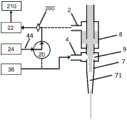
图1是包括本发明的内部气动阻挡系统的印刷头的实施例的示意图,其示出了印刷配置下的流动和气溶胶分布。Figure 1 is a schematic diagram of an embodiment of a print head including an internal pneumatic barrier system of the present invention showing flow and aerosol distribution in a printing configuration.
图2是当图1的装置被初始地切换到转移配置时装置中的流动和气溶胶分布的示意图。Figure 2 is a schematic diagram of flow and aerosol distribution in the device of Figure 1 when it is initially switched to a transfer configuration.
图3是在转移配置下的当已停止了穿过印刷喷嘴的所有气溶胶流时图1的装置中的流动和气溶胶分布的示意图。Figure 3 is a schematic illustration of the flow and aerosol distribution in the device of Figure 1 in a transfer configuration when all aerosol flow through the print nozzles has been stopped.
图4是当已恢复印刷配置时图1的装置中的流动和气溶胶分布的示意图。Figure 4 is a schematic illustration of the flow and aerosol distribution in the device of Figure 1 when the printing configuration has been restored.
图5是当在瞬时阻挡之后恢复印刷时图1的装置中的流动的示意图。Figure 5 is a schematic illustration of the flow in the apparatus of Figure 1 when printing is resumed after a momentary block.
图6是在部分阻挡(即部分转移)期间图1的装置中的流动的示意图。Figure 6 is a schematic illustration of flow in the device of Figure 1 during partial blocking (ie partial transfer).
图7是图1的装置中的气溶胶流的速度分布的示意图。FIG. 7 is a schematic diagram of the velocity profile of the aerosol flow in the device of FIG. 1 .
图8是类似于图1的装置、但采用预鞘气的装置中的气溶胶流的速度分布的示意图。Figure 8 is a schematic diagram of the velocity profile of the aerosol flow in a device similar to the device of Figure 1 but employing a pre-sheath gas.
具体实施方式Detailed ways
本发明的实施例是一种用于快速阻挡气溶胶流或被覆盖的气溶胶流的设备和方法,该设备和方法可以应用于但不限于需要协调地阻挡流体的过程,例如用于直写式电子器件的离散结构的基于气溶胶的印刷、用于气溶胶输送应用或用于各种三维印刷应用。流体流可以包括液体悬浮液中的固体颗粒、液滴或其组合。如本文所使用的,可以互换使用的术语“滴”或“颗粒”是指液滴、具有悬浮的固体颗粒的液体或其混合物。本发明提供了一种方法和设备,该方法和设备能够实现气溶胶流中的墨滴的受控的完全或部分式开-关沉积,以利用Aerosol
在本发明的一个或更多个实施例中,内部挡板被并入到设备中以用于使用气动聚集来高分辨率地、无掩模地沉积液体油墨。该设备通常包括雾化器,该雾化器用于通过将液体雾化成细小微滴来产生雾。然后,雾化后的雾通过载气流被输送到沉积喷嘴,以引导和聚集气溶胶雾流。设备还优选地包括用于自动地控制工艺参数的控制模块和驱动衬底相对于沉积喷嘴的相对运动的运动控制模块。液体油墨的气溶胶化可以通过多种方法来实现,包括使用超声雾化器或气动雾化器。使用具有汇聚通道的Aerosol


图1示出了包括本发明的内部阻挡的实施例的印刷头。印刷头包括内部雾切换室8。由雾化器产生的气溶胶流6优选地穿过印刷头的顶部进入印刷头并沿箭头所示的方向移动。雾流量M优选地在气溶胶流6的印刷和转移期间保持稳定。在印刷期间,气溶胶流6优选地从顶部进入印刷头,并穿过上雾管26行进到雾切换室8,然后穿过中雾管5到达鞘增压室9,在该鞘增压室9处,气溶胶流6被来自鞘质量流量控制器36的鞘气流32包围,然后气溶胶流6穿过下雾管7到达沉积喷嘴1并离开喷嘴末端10。具有流量S的鞘气流32(优选地从诸如压缩气缸之类的气体供应器输送所述鞘气流32并且通过质量流量控制器36控制所述鞘气流32)优选地通过鞘增压入口4被引入到印刷头中,以形成在鞘增压室9中的包裹在气溶胶流周围的优选轴对称的、环形的、共同流动的鞘,从而保护下雾管7和沉积喷嘴1的壁免受气溶胶的滴的影响。鞘气还用于聚集气溶胶流,使得能够沉积较小直径的特征。在印刷期间,三通阀20被配置成使得来自增压质量流量控制器24的增压气体流44不进入鞘增压室9,而是绕过印刷头并通过排气质量流量控制器22离开系统。Figure 1 shows a print head including an embodiment of the internal barrier of the present invention. The print head includes an internal
如图2所示,为了实现气溶胶流的阻挡或转移,三通阀20进行切换,使得具有流速B的增压气体流44(优选地由诸如压缩气缸之类的气体供应器供应所述增压气体流44并且通过质量流量控制器24控制所述增压气体流44)与鞘气流32结合,并通过鞘增压入口4进入印刷头。排气流46通过排气出口2离开印刷头,并使气溶胶流6转移离开中雾管5。当结合后的鞘气流32和增压气体流44通过鞘增压入口4进入鞘增压室9时,它们被分成沿向上方向(即,与气溶胶流6的流动方向相反的方向)和向下方向两者的相等的或不相等的流。当结合后的鞘气流和增压气体流的一部分朝向喷嘴末端10向下行进时,该部分将位于鞘增加室9和沉积喷嘴末端10之间的气溶胶颗粒通过喷嘴末端10推出。As shown in Figure 2, in order to achieve blocking or diversion of the aerosol flow, the three-
在将剩余的气溶胶从喷嘴末端10清除之后(这可能大约需要5到50毫秒(依赖于气体流量)),印刷停止,如图3所示。当正在清除沉积喷嘴1中的气溶胶流时,结合后的增压气体流和鞘气流的上部部分将中雾管5中的剩余的气溶胶流6朝向排气出口2向上推动。气溶胶流6继续离开上雾管26并从排气出口2转移出。来自排气出口2的具有流量E的净流出排气流优选地由真空泵210驱动,优选地在大约七磅的真空度下运行,并且由排气质量流量控制器22控制。如在整个说明书和权利要求书中使用的,术语“真空泵”是指真空泵或任何其它产生吸力的设备。由于流量控制装置通常包含具有较小孔口或较小通道的阀,因而如果载有油墨的排气流穿过这些阀则这些阀可能会被污染或甚至损坏,因此优选地在排气出口2和排气质量流量控制器22之间设置雾颗粒过滤器或其它过滤机构200。After the remaining aerosol has been purged from the nozzle tip 10 (which may take approximately 5 to 50 milliseconds (depending on the gas flow)), printing stops, as shown in FIG. 3 . When the aerosol flow in the
当恢复印刷配置时,如图4所示,增压气体流和排气流不流经印刷头,并且在中雾管5中没有向上的流动。在印刷配置中,三通阀20被切换成使得增压气体流44绕过印刷头。鞘质量流量控制器36继续向鞘增压入口4供应鞘气流32。气溶胶流6的前缘恢复了朝向印刷头向下穿过雾切换室8的基本为抛物线的流动轮廓48,其首先填充中雾管5,然后被鞘气流32包围,此后共同流动的气溶胶流6和鞘气流流入到沉积喷嘴1中,并最后穿过喷嘴末端10。当从转移切换到印刷时,在将恢复印刷之前气溶胶流6向下穿过中雾管5、鞘增压室9和沉积喷嘴1。中雾管5和下雾管7的较小的长度和内径是优选的,以最小化开/关延迟。从转移功能到印刷功能的切换可以仅在短达10毫秒内完成。从印刷到转移的切换可以仅在短达5毫秒内完成,这依赖于喷嘴或孔口尺寸、增压流量和鞘流量。When the printing configuration is restored, as shown in FIG. 4 , the flow of pressurized gas and exhaust gas does not flow through the print head, and there is no upward flow in the
雾切换室8优选地定位成尽可能地靠近喷嘴末端10,以最小化与气溶胶流6必须从雾切换室8行进至沉积喷嘴末端10的距离相关联的雾流响应时间。类似地,优选地最小化中雾管5、下雾管7和沉积喷嘴1的内径以增加流的速度,从而最小化从雾切换室8到喷嘴末端10的出口的雾传送时间。如图所示,优选地利用质量流量控制器来实现系统中各个流的流量控制,以在生产运行的长持续时间内提供精确的流量。可替代地,孔口型流量计或转子流量计的流量控制对于低成本应用而言可能是优选的。此外,为了最大化系统的稳定性并最小化转换时间,M和S优选地在所有时间都保持近似恒定,包括在印刷模式和转移模式两者期间、以及在阻挡转换期间。The
为了最小化阻挡转换时间,印刷头中的压力优选地在印刷期间、在阻挡期间、以及在印刷和阻挡之间的转换期间保持恒定。如果喷嘴通道3中的流具有流量N,则优选地M+S+B=E+N。在印刷模式下,B=0且E=0,因此N=M+S。此外,鞘增压室9内部的压力优选地保持恒定以最小化阻挡转换时间。由于该压力由穿过喷嘴末端10的总流量的背压确定,因此穿过喷嘴末端10的净流量优选地在所有运行模式期间以及在所有运行模式之间的转换期间保持相同。因此,在完全阻挡期间,E和S优选地被选择为使得N=M+S。在阻挡期间,E=M+f(B+S),其中f是结合后的增压流和鞘流的向上转移的一部分,并且N=M+S=(1-f)(B+S)。如果装置中的流量满足这些条件(即,在印刷期间喷嘴通道3中的雾的流量M在转移期间基本上被(1-f)B-fS替代,使得离开喷嘴的流的总流量N是恒定的),则喷嘴通道3中的鞘气流流线优选地通过基本不受到引导增压流B穿过印刷头的干扰,从而停止印刷。To minimize blocking transition time, the pressure in the print head is preferably kept constant during printing, during blocking, and during transitions between printing and blocking. If the flow in the
对于完全转移的流,求解这些方程式得出E=B;因此,质量流量控制器22和24优选地被设置为使得E=B,以实现完全的流转移。为了确保气溶胶流的完全的内部阻挡或转移,增压气体流44的流量B优选地大于气溶胶流6的流量M;优选为气溶胶流的流量M的约1.2-2倍;并且更优选地,在大多数应用中,B约为2M以实现稳定、完全的雾切换。For a fully diverted flow, solving these equations yields E=B; therefore, the
在一个理论性示例中,如果气溶胶流6的流量为M=50sccm,并且鞘气流32的流量S为55sccm,则在印刷期间,喷嘴通道3中的(并由此离开喷嘴末端10的)流量为M+S=105sccm。在这种模式下,由于增压气体流44没有进入印刷头,并且没有任何流离开排气出口2,因此B=E=0(尽管在实际上,如上所述,为了保持稳定性,质量流量控制器44被设置为提供100sccm的流,该100sccm的流通过三通阀20转移以直接流向质量流量控制器42,该质量流量控制器42被设置为将100sccm的流传递到真空泵210)。当期望完全转移时,将增压气体流44的流量B(以及如上得出的排气流46的流量E)优选地选被择为使得B=E=2M=100sccm以实现雾转移。在气溶胶流的转移或阻挡期间,总流量为S+B=155sccm的结合后的鞘流和增压流在鞘增压室9内分流,使得N=105sccm的结合后的流有效地向下流过下雾管7和沉积喷嘴1,从而替换现在正在雾切换室8中转移的气溶胶流6(和鞘流32)。由于在质量流量控制器22中将E设置为100sccm,因此50sccm的分流的结合后的流向上流动,将剩余的气溶胶流6从中雾管5冲入到切换室8中,在该切换室8处该剩余的气溶胶流6与转移的气溶胶流结合。因此,离开排气出口2的排气流46等于气溶胶流的流量M与增压气体的向上部分的流量相加之和,即E=100sccm。流入印刷头中的总流量(M+B+S=205sccm)等于流出印刷头的总流量(N+E=205sccm)。通常,平衡后的流量允许实现鞘增压室9内的恒定压力,这导致可以用最小化的阻挡时间来完全开启和断开(即阻挡)气溶胶流。In one theoretical example, if the flow rate of the
混合阻挡Hybrid blocking
与机械阻挡相比,通过将气溶胶流转移到排气出口2的内部气动阻挡可以运行较长的时间段而不会产生不利影响,而对于机械阻挡而言,积聚在机械挡板(为了阻止气溶胶流而插入所述机械挡板)上的油墨可能会使印刷头的气动表面或衬底移位并受到污染。内部气动挡板可以单独地使用,或可以与另一阻挡技术结合使用,例如与机械阻挡结合使用,以在利用机械阻挡的快速响应的同时最小化机械挡板臂的顶部上的油墨积聚。在该实施例中,当停止印刷时,机械挡板被激活以阻止气溶胶流。如上所述,气动阻挡在大部分阻挡持续时间内使油墨远离机械挡板220而转移,因此减少了油墨在机械挡板上的积聚。因为与较快的机械挡板相比,气动挡板激活地较慢,所以优选在某个时间处触发气动挡板,使得较快的机械挡板首先关闭,并且气动挡板在机械挡板关闭之后尽可能快地关闭。为了恢复印刷,优选地首先打开气动挡板以使输出稳定,然后打开机械挡板220。尽管机械挡板可以位于印刷头内的任何位置,甚至可以位于沉积喷嘴的外部,但是机械冲击式阻挡优选地靠近气溶胶流离开沉积喷嘴的位置。Internal pneumatic blocking by diverting the aerosol flow to the
瞬时阻挡momentary block
在本发明的可替代的实施例中,内部挡板可以用作瞬时挡板,对于该瞬时挡板,气溶胶流的转移发生在足够短的时间段内,使得没有时间使印刷头中的气溶胶分布达到平衡。图2示出了在切换三通阀20之后即刻的气溶胶分布,其中切换三通阀20以将增压气体流44添加至鞘增压入口4并从排气口2排出排气流46。在鞘增压室9中产生的气溶胶中的间隙向下通过下雾管7扩大并且向上通过中雾管5扩大。In an alternative embodiment of the present invention, the internal baffle may act as a momentary baffle for which the transfer of the aerosol flow occurs for a period of time short enough that there is no time for the aerosol in the print head to drain The sol distribution reaches equilibrium. FIG. 2 shows the aerosol distribution immediately after switching the three-
如图5所示,当三通阀20迅速切回至转移增压气体流44使得增压气体流44不进入印刷头,中雾管5中的雾再次向下行进穿过鞘增压室9并进入下雾管7中。气溶胶流中的间隙71可以非常短,大约为10ms的量级,并且可以非常快速地发生到完全关闭和完全开启的转变。优选地,向上移动的清洁气体保留在中雾管5内,使得当恢复向下的流动时,该清洁气体与向上的流动模式对称地向下流动。也就是说,就如在中管5中在向上的流的中心的较高的速度附近产生清洁气体的向上隆起(如图2所示)一样,返回的雾的高速中心流使所述隆起塌陷并在所述雾从中管5的底部出现时形成基本平坦的雾前部。因此,就如在转移开始时气溶胶流在鞘增压室9中被清洁气体流突然切断一样,当恢复印刷时,气溶胶的向下的流的前边界优选地重新形成,以使该向下的流基本上突然进入到鞘增压室9中,从而在衬底处产生较短的最初开启到完全开启的时间。如果在转移时清洁气体的前表面从中管5的顶部出现并进入到雾切换室8中,则清洁气体横向地分散到该室中。当恢复气溶胶流时,清洁气体不会完全返回到中雾管5,并且所述雾的最初开启到完全开启时间变短。清洁气体在中雾管5中的停留时间由管的体积与清洁气体的向上流量的关系确定。较低的向上流量(例如B=E=1.2M)通常用于产生较慢的上向的流。可以增加中雾管5的长度或直径,以增加清洁气体在中管中的停留时间和可允许转移的持续时间。当以气溶胶输出中的较短间隙来印刷图案(例如具有小间距端部的重复的点或线)时,瞬时阻挡很大程度地减少了阻挡时间并改善了阻挡质量。As shown in FIG. 5 , when the three-
部分阻挡partial block
较高的气溶胶流量M通常用于提供大量的油墨输出并产生较粗的特征,而较低的流量通常用于产生较细的特征。通常期望在相同的图案中印刷较大的特征和较细的特征,例如当使用细束跟踪图案的周界并使用粗束来填充周界的同时保持M恒定。在图6所示的本发明的可替代的实施例中,内部挡板可以用于部分地转移气溶胶流6,以通过在印刷时将一部分雾转移到排气出口2来改变流向沉积喷嘴的雾流量。因此,即使在印刷期间,也总有一些气溶胶流6被转移出排气口2,只有一部分雾进入到中管5中。通过改变排气流量E、增压气体流量B和雾流量M之间的平衡,可以改变有效雾流量和印刷出的线宽。当完全转移时,增压流量B优选地大于或等于雾流量M,如上所述。如果B小于M,则一些雾将仍沿着中雾管5向下行进并行进出沉积喷嘴1,并且气溶胶将仅被部分地转移。Higher aerosol flow rates M are generally used to provide substantial ink output and produce coarser features, while lower flow rates are generally used to produce finer features. It is often desirable to print larger features and finer features in the same pattern, for example when using a thin beam to trace the perimeter of the pattern and a coarse beam to fill the perimeter while keeping M constant. In an alternative embodiment of the invention shown in Figure 6, an internal baffle may be used to partially divert the
在一个理论性示例中,期望气溶胶流的一半被转移并且一半被印刷。如果气溶胶流6的流量为M=50sccm,而鞘气流32的流量S为55sccm,则对于部分阻挡而言,在该示例中增压气体流44的流量B被选择为使得B=1/2M=25sccm。质量流量控制器22被设置为使得E=65sccm,因此总流量为S+B=80sccm的结合后的鞘流和增压流在鞘增压室9中平均地分流,使得40sccm的结合后的流向下流动穿过下雾管7和沉积喷嘴1。因此,N为40sccm+(1/2M)=65sccm,并且流入到印刷头中的总流量(50+55+25=130sccm)等于流出印刷头的总流量(65+65=130sccm)。可替代地,可以将E设置为等于75sccm,在这种情况下,结合后的增压流和鞘流被分流,使得50sccm向上流动(因为75-25=50),并且30sccm向下流动。因此,N=30+25=55sccm,并且输入流量(50+55+25=130sccm)再次等于输出流量(75+55=130sccm)。应当注意,对于部分阻挡而言,E>B,并且系统处于平衡的压力(130sccm)低于完全阻挡期间的压力(205sccm),并且高于正常印刷期间的压力(105sccm),如先前示例所示。In one theoretical example, half of the aerosol flow is expected to be diverted and half to be printed. If the flow rate of the
通常,B>M用于所述雾的完全转移或阻挡或瞬时阻挡,从而阻止印刷,而B<M或B=M用于减少印刷期间的雾输出并产生较细的特征。对于B<M的每个B都会导致离开沉积喷嘴1的不同的雾流量。因此,如果可以产生至少两个水平的增压流,一个为B>M,另一个为B<M,则可以同时实现雾流量的减少和完全转移。这可以例如通过快速地改变增压质量流量控制器24的设置来实现,或可替代地通过采用第二增压质量流量控制器来实现。在后一种情况下,可以将一个增压质量流量控制器(MFC)设置为例如处于2M的流量以完全关闭所述雾,而另一个增压质量流量控制器被设置为例如处于1/2M的流量以减少M的流出喷嘴1的部分。Typically, B>M is used for complete transfer or blocking or instantaneous blocking of the fog, preventing printing, while B<M or B=M is used to reduce fog output during printing and produce finer features. Each B for B<M results in a different mist flow rate exiting the
因为排气流和增压气体流可以在小于约一秒的时间内稳定,而在M改变时雾化器的输出可能需要10秒以上的时间达到稳定,所以利用部分转移来改变质量输出和线宽比改变输入的气溶胶流6的流量M更优选。可替代地,可以使用使现有的流和控制阀分流的第二流或孔口以产生具有快速响应时间的变化的雾输出。Because the exhaust and boost gas flows can stabilize in less than about a second, while the nebulizer output can take more than 10 seconds to stabilize when M is changed, partial transfer is used to vary the mass output and line It is more preferred to vary the flow rate M of the
预鞘气Pre-sheathed gas
在本发明中优选地执行的气溶胶喷印中通常采用的层流条件下,圆柱形管中的气体形成抛物线速度分布,其中在管的中心处的速度是平均速度的两倍,而在管壁附近的速度接近于零。图4示出了在转移之后重新建立的气溶胶的流,其中所述雾的前缘遵循该抛物线流动轮廓48。在中雾管5的壁附近缓慢移动的雾的穿行时间与在中雾管5的中心处快速移动的雾的穿行时间之间的差主要决定了在衬底处气溶胶的最初开启和完全开启之间的延迟。虽然理论上在中管的壁附近的零速度的雾需要花费无限长的时间来到达鞘增压室,但实际上在开启挡板之后(即在切换三通阀20时),在快速移动的雾到达鞘增压室所需的时间的约2-3倍的时间之后,基本上实现了全输出。图7示出了中雾管5中的速度分布91和下雾管7中的速度分布92。下管中所述雾的速度大于中管中所述雾的速度,其原因有两个:首先,由于在鞘增压室9中已将鞘气流32添加至气溶胶流6中,因此优选地形成围绕所述雾的轴对称的环形的鞘;并且其次,下雾管7中的雾被限制为流的中心的、快速移动的部分。因此,在鞘气流的情况下,在管壁附近缓慢移动的是清洁的鞘气的套筒;气溶胶本身处于气体速度分布的高速区域中。因此,所述雾分布的中心和边缘穿过下雾管7和沉积喷嘴1的时间的变化相对较小。Under the laminar flow conditions typically employed in aerosol jet printing, which is preferably performed in the present invention, the gas in the cylindrical tube forms a parabolic velocity profile, where the velocity at the centre of the tube is twice the average velocity, and The velocity near the wall is close to zero. FIG. 4 shows the re-established flow of the aerosol after transfer, with the leading edge of the fog following this
由于该优点,可以在雾进入雾切换室8和/或中雾管5之前添加围绕所述雾流的“预鞘”,以消除在中雾管5的壁附近缓慢移动的雾。图8示出了预鞘气95经由预鞘输入口94进入预鞘室93,该预鞘气95优选地形成围绕气溶胶流6的清洁气体的轴对称的、环形的套筒。在一些实施例中,全部鞘流的大约一半被引导至预鞘输入口94中,而另一半则被引导至鞘增压输入口4中。将50%的鞘流提供给预鞘气流,导致了气溶胶流的最初开启开启和完全开启之间的延迟减少约80%。由于预鞘流和鞘流在鞘增压室9中重新结合,因此在采用或不采用预鞘气流的情况下,衬底上的沉积特征几乎没有差异。Due to this advantage, a "pre-sheath" around the mist flow can be added before the mist enters the
应当注意,在说明书和权利要求书中,“大约”或“约”是指在所引用数值的百分之二十(20%)内。如在本文中所使用的,单数形式的表述“一”、“一个”和“所述”包括复数形式的指代物,除非上下文另外明确指出。因此,例如,对“功能组”的引用是指一个或更多个功能组,并且对“方法”的引用包括引用本领域技术人员将明白和理解的等同步骤和方法,等等。It should be noted that, in the specification and claims, "about" or "about" means within twenty percent (20%) of the recited value. As used herein, the singular expressions "a," "an," and "the" include plural referents unless the context clearly dictates otherwise. Thus, for example, reference to a "functional group" refers to one or more functional groups, and reference to a "method" includes references to equivalent steps and methods that will be understood and understood by those skilled in the art, and so forth.
尽管已特别参考所公开的实施例详细地描述了本发明,但其它实施例可以实现相同的结果。本领域技术人员将明白本发明的变化和修改,并且所述变化和修改旨在涵盖所有这样的修改和等同物。以上引用的所有专利和出版物的全部公开内容由此通过引用并入。Although the present invention has been described in detail with particular reference to the disclosed embodiments, other embodiments may achieve the same results. Variations and modifications of the present invention will be apparent to those skilled in the art and are intended to cover all such modifications and equivalents. The entire disclosures of all patents and publications cited above are hereby incorporated by reference.
Claims (28)
Translated fromChineseApplications Claiming Priority (3)
| Application Number | Priority Date | Filing Date | Title |
|---|---|---|---|
| US201762585449P | 2017-11-13 | 2017-11-13 | |
| US62/585,449 | 2017-11-13 | ||
| PCT/US2018/060853WO2019094979A1 (en) | 2017-11-13 | 2018-11-13 | Shuttering of aerosol streams |
Publications (2)
| Publication Number | Publication Date |
|---|---|
| CN111655382Atrue CN111655382A (en) | 2020-09-11 |
| CN111655382B CN111655382B (en) | 2022-05-31 |
Family
ID=66431717
Family Applications (1)
| Application Number | Title | Priority Date | Filing Date |
|---|---|---|---|
| CN201880086367.6AActiveCN111655382B (en) | 2017-11-13 | 2018-11-13 | Blocking of aerosol flow |
Country Status (6)
| Country | Link |
|---|---|
| US (2) | US10632746B2 (en) |
| EP (1) | EP3723909B1 (en) |
| KR (1) | KR20200087196A (en) |
| CN (1) | CN111655382B (en) |
| TW (1) | TWI767087B (en) |
| WO (1) | WO2019094979A1 (en) |
Cited By (6)
| Publication number | Priority date | Publication date | Assignee | Title |
|---|---|---|---|---|
| CN113199776A (en)* | 2021-03-15 | 2021-08-03 | 厦门理工学院 | Nanoparticle aerosol jet printing method and device |
| CN114643141A (en)* | 2020-12-21 | 2022-06-21 | 普罗科技有限公司 | Viscous solution aerosol spraying device |
| CN114985772A (en)* | 2022-06-02 | 2022-09-02 | 临沂大学 | A complex curved surface printing device and forming method based on micro-nano electronic manufacturing |
| CN115218125A (en)* | 2022-07-20 | 2022-10-21 | 广州卓诚智能装备有限公司 | Reversing structure |
| CN115990551A (en)* | 2021-10-20 | 2023-04-21 | 蒋恒 | Method for producing a jet of liquid glue |
| CN117320818A (en)* | 2021-04-29 | 2023-12-29 | 奥普托美克公司 | High-reliability sheathed transport path for aerosol spray devices |
Families Citing this family (10)
| Publication number | Priority date | Publication date | Assignee | Title |
|---|---|---|---|---|
| NL2022412B1 (en) | 2019-01-17 | 2020-08-18 | Vsparticle Holding B V | Switching device, deposition device comprising the switching device, method for switching a fluid flow, and method for depositing particles onto a substrate |
| CN110763611A (en)* | 2019-10-18 | 2020-02-07 | 中国科学院大气物理研究所 | Aerosol particle beam injection device based on sheath air streaming principle |
| DE102020206926A1 (en) | 2020-06-03 | 2021-12-09 | Robert Bosch Gesellschaft mit beschränkter Haftung | Media application device, media application system and method for a directed output of a medium by means of the media application device |
| EP3943197A1 (en)* | 2020-07-20 | 2022-01-26 | The Provost, Fellows, Scholars and other Members of Board of Trinity College Dublin | Jet deposition using laser-produced dry aerosol |
| US20220088925A1 (en)* | 2020-09-21 | 2022-03-24 | Integrated Deposition Solutions, Inc. | High-definition aerosol printing using an optimized aerosol distribution and aerodynamic lens system |
| US12162035B2 (en) | 2021-07-28 | 2024-12-10 | Oregon State University | Print head for printing nanomaterials |
| CN114985775B (en)* | 2022-06-02 | 2024-07-16 | 临沂大学 | Spray head device based on aerosol three-dimensional printing |
| CN120202069A (en)* | 2022-11-29 | 2025-06-24 | 奥普托美克公司 | High reliability armored aerosol flow splitter |
| KR102670828B1 (en)* | 2023-02-15 | 2024-05-30 | 순천향대학교 산학협력단 | Focused spray jet printing system |
| CN119840165A (en)* | 2025-01-26 | 2025-04-18 | 华中科技大学 | Aerosol jet printing device and method capable of being rapidly stopped |
Citations (10)
| Publication number | Priority date | Publication date | Assignee | Title |
|---|---|---|---|---|
| US4019188A (en)* | 1975-05-12 | 1977-04-19 | International Business Machines Corporation | Micromist jet printer |
| JPH08238784A (en)* | 1995-02-16 | 1996-09-17 | Hewlett Packard Co <Hp> | Method and device for reducing aerosol in ink jet printer |
| WO2001038002A1 (en)* | 1999-09-13 | 2001-05-31 | Sheffield Pharmaceuticals, Inc. | Aerosol airflow control system and method |
| US20020100416A1 (en)* | 2001-01-30 | 2002-08-01 | Sun James J. | Method and apparatus for deposition of particles on surfaces |
| US6511850B1 (en)* | 1999-07-13 | 2003-01-28 | The Texas A&M University System | Pneumatic nebulizing interface to convert an analyte-containing fluid stream into an aerosol, method for using same and instruments including same |
| US20030156152A1 (en)* | 2001-12-26 | 2003-08-21 | Ray John F. | Cleaning nozzle |
| JP2008088451A (en)* | 2006-09-29 | 2008-04-17 | Fujifilm Corp | Film forming method and film forming apparatus |
| US20090252874A1 (en)* | 2007-10-09 | 2009-10-08 | Optomec, Inc. | Multiple Sheath Multiple Capillary Aerosol Jet |
| CN102307670A (en)* | 2009-02-06 | 2012-01-04 | 弗劳恩霍弗应用技术研究院 | Aerosol printing machine and purpose thereof, and method for generating line interruption in a continuous aerosol printing method |
| CN104114737A (en)* | 2011-12-14 | 2014-10-22 | 普莱克斯S.T.技术有限公司 | System and method for utilization of shrouded plasma spray or shrouded liquid suspension injection in suspension plasma spray processes |
Family Cites Families (343)
| Publication number | Priority date | Publication date | Assignee | Title |
|---|---|---|---|---|
| US3474971A (en) | 1967-06-14 | 1969-10-28 | North American Rockwell | Two-piece injector |
| DE1984101U (en) | 1968-02-12 | 1968-04-25 | Waltraud Gollong | HYGIENIC PROTECTIVE TROUSERS. |
| US3590477A (en) | 1968-12-19 | 1971-07-06 | Ibm | Method for fabricating insulated-gate field effect transistors having controlled operating characeristics |
| US3808550A (en) | 1969-12-15 | 1974-04-30 | Bell Telephone Labor Inc | Apparatuses for trapping and accelerating neutral particles |
| US3642202A (en) | 1970-05-13 | 1972-02-15 | Exxon Research Engineering Co | Feed system for coking unit |
| US3808432A (en) | 1970-06-04 | 1974-04-30 | Bell Telephone Labor Inc | Neutral particle accelerator utilizing radiation pressure |
| US3846661A (en) | 1971-04-29 | 1974-11-05 | Ibm | Technique for fabricating integrated incandescent displays |
| US3715785A (en) | 1971-04-29 | 1973-02-13 | Ibm | Technique for fabricating integrated incandescent displays |
| US3777983A (en) | 1971-12-16 | 1973-12-11 | Gen Electric | Gas cooled dual fuel air atomized fuel nozzle |
| US3816025A (en) | 1973-01-18 | 1974-06-11 | Neill W O | Paint spray system |
| US3854321A (en) | 1973-04-27 | 1974-12-17 | B Dahneke | Aerosol beam device and method |
| US3901798A (en) | 1973-11-21 | 1975-08-26 | Environmental Research Corp | Aerosol concentrator and classifier |
| US4036434A (en) | 1974-07-15 | 1977-07-19 | Aerojet-General Corporation | Fluid delivery nozzle with fluid purged face |
| US3982251A (en) | 1974-08-23 | 1976-09-21 | Ibm Corporation | Method and apparatus for recording information on a recording medium |
| US3959798A (en) | 1974-12-31 | 1976-05-25 | International Business Machines Corporation | Selective wetting using a micromist of particles |
| DE2517715C2 (en) | 1975-04-22 | 1977-02-10 | Hans Behr | PROCESS AND DEVICE FOR MIXING AND / OR DISPERSING AND BLASTING THE COMPONENTS OF A FLOWABLE MATERIAL FOR COATING SURFACES |
| US3974769A (en) | 1975-05-27 | 1976-08-17 | International Business Machines Corporation | Method and apparatus for recording information on a recording surface through the use of mists |
| US4004733A (en) | 1975-07-09 | 1977-01-25 | Research Corporation | Electrostatic spray nozzle system |
| US4016417A (en) | 1976-01-08 | 1977-04-05 | Richard Glasscock Benton | Laser beam transport, and method |
| US4046073A (en) | 1976-01-28 | 1977-09-06 | International Business Machines Corporation | Ultrasonic transfer printing with multi-copy, color and low audible noise capability |
| US4046074A (en) | 1976-02-02 | 1977-09-06 | International Business Machines Corporation | Non-impact printing system |
| US4034025A (en) | 1976-02-09 | 1977-07-05 | Martner John G | Ultrasonic gas stream liquid entrainment apparatus |
| US4092535A (en) | 1977-04-22 | 1978-05-30 | Bell Telephone Laboratories, Incorporated | Damping of optically levitated particles by feedback and beam shaping |
| US4171096A (en) | 1977-05-26 | 1979-10-16 | John Welsh | Spray gun nozzle attachment |
| US4112437A (en) | 1977-06-27 | 1978-09-05 | Eastman Kodak Company | Electrographic mist development apparatus and method |
| US4235563A (en) | 1977-07-11 | 1980-11-25 | The Upjohn Company | Method and apparatus for feeding powder |
| JPS592617B2 (en) | 1977-12-22 | 1984-01-19 | 株式会社リコー | ink jetting device |
| US4132894A (en) | 1978-04-04 | 1979-01-02 | The United States Of America As Represented By The United States Department Of Energy | Monitor of the concentration of particles of dense radioactive materials in a stream of air |
| US4200669A (en) | 1978-11-22 | 1980-04-29 | The United States Of America As Represented By The Secretary Of The Navy | Laser spraying |
| GB2052566B (en) | 1979-03-30 | 1982-12-15 | Rolls Royce | Laser aplication of hard surface alloy |
| US4323756A (en) | 1979-10-29 | 1982-04-06 | United Technologies Corporation | Method for fabricating articles by sequential layer deposition |
| JPS5948873B2 (en) | 1980-05-14 | 1984-11-29 | ペルメレック電極株式会社 | Method for manufacturing electrode substrate or electrode provided with corrosion-resistant coating |
| US4453803A (en) | 1981-06-25 | 1984-06-12 | Agency Of Industrial Science & Technology | Optical waveguide for middle infrared band |
| US4605574A (en) | 1981-09-14 | 1986-08-12 | Takashi Yonehara | Method and apparatus for forming an extremely thin film on the surface of an object |
| US4485387A (en) | 1982-10-26 | 1984-11-27 | Microscience Systems Corp. | Inking system for producing circuit patterns |
| US4685563A (en) | 1983-05-16 | 1987-08-11 | Michelman Inc. | Packaging material and container having interlaminate electrostatic shield and method of making same |
| US4497692A (en) | 1983-06-13 | 1985-02-05 | International Business Machines Corporation | Laser-enhanced jet-plating and jet-etching: high-speed maskless patterning method |
| US4601921A (en) | 1984-12-24 | 1986-07-22 | General Motors Corporation | Method and apparatus for spraying coating material |
| US4694136A (en) | 1986-01-23 | 1987-09-15 | Westinghouse Electric Corp. | Laser welding of a sleeve within a tube |
| US4689052A (en) | 1986-02-19 | 1987-08-25 | Washington Research Foundation | Virtual impactor |
| US4823009A (en) | 1986-04-14 | 1989-04-18 | Massachusetts Institute Of Technology | Ir compatible deposition surface for liquid chromatography |
| US4670135A (en) | 1986-06-27 | 1987-06-02 | Regents Of The University Of Minnesota | High volume virtual impactor |
| JPS6359195A (en) | 1986-08-29 | 1988-03-15 | Hitachi Ltd | magnetic recording and reproducing device |
| EP0261296B1 (en) | 1986-09-25 | 1992-07-22 | Laude, Lucien Diégo | Apparatus for laser-enhanced metal electroplating |
| US4733018A (en) | 1986-10-02 | 1988-03-22 | Rca Corporation | Thick film copper conductor inks |
| US4927992A (en) | 1987-03-04 | 1990-05-22 | Westinghouse Electric Corp. | Energy beam casting of metal articles |
| US4724299A (en) | 1987-04-15 | 1988-02-09 | Quantum Laser Corporation | Laser spray nozzle and method |
| US4904621A (en) | 1987-07-16 | 1990-02-27 | Texas Instruments Incorporated | Remote plasma generation process using a two-stage showerhead |
| US4893886A (en) | 1987-09-17 | 1990-01-16 | American Telephone And Telegraph Company | Non-destructive optical trap for biological particles and method of doing same |
| US4997809A (en) | 1987-11-18 | 1991-03-05 | International Business Machines Corporation | Fabrication of patterned lines of high Tc superconductors |
| US4920254A (en) | 1988-02-22 | 1990-04-24 | Sierracin Corporation | Electrically conductive window and a method for its manufacture |
| JPH0621335B2 (en) | 1988-02-24 | 1994-03-23 | 工業技術院長 | Laser spraying method |
| US4895735A (en) | 1988-03-01 | 1990-01-23 | Texas Instruments Incorporated | Radiation induced pattern deposition |
| US4917830A (en) | 1988-09-19 | 1990-04-17 | The United States Of America As Represented By The United States Department Of Energy | Monodisperse aerosol generator |
| US4971251A (en) | 1988-11-28 | 1990-11-20 | Minnesota Mining And Manufacturing Company | Spray gun with disposable liquid handling portion |
| US5614252A (en) | 1988-12-27 | 1997-03-25 | Symetrix Corporation | Method of fabricating barium strontium titanate |
| US6056994A (en) | 1988-12-27 | 2000-05-02 | Symetrix Corporation | Liquid deposition methods of fabricating layered superlattice materials |
| US4911365A (en) | 1989-01-26 | 1990-03-27 | James E. Hynds | Spray gun having a fanning air turbine mechanism |
| US5043548A (en) | 1989-02-08 | 1991-08-27 | General Electric Company | Axial flow laser plasma spraying |
| US5038014A (en) | 1989-02-08 | 1991-08-06 | General Electric Company | Fabrication of components by layered deposition |
| US5064685A (en) | 1989-08-23 | 1991-11-12 | At&T Laboratories | Electrical conductor deposition method |
| US5017317A (en) | 1989-12-04 | 1991-05-21 | Board Of Regents, The Uni. Of Texas System | Gas phase selective beam deposition |
| US5032850A (en) | 1989-12-18 | 1991-07-16 | Tokyo Electric Co., Ltd. | Method and apparatus for vapor jet printing |
| US4978067A (en) | 1989-12-22 | 1990-12-18 | Sono-Tek Corporation | Unitary axial flow tube ultrasonic atomizer with enhanced sealing |
| DE4000690A1 (en) | 1990-01-12 | 1991-07-18 | Philips Patentverwaltung | PROCESS FOR PRODUCING ULTRAFINE PARTICLES AND THEIR USE |
| US5250383A (en) | 1990-02-23 | 1993-10-05 | Fuji Photo Film Co., Ltd. | Process for forming multilayer coating |
| DE4006511A1 (en) | 1990-03-02 | 1991-09-05 | Krupp Gmbh | DEVICE FOR FEEDING POWDERED ADDITIVES IN THE AREA OF A WELDING POINT |
| US5176328A (en) | 1990-03-13 | 1993-01-05 | The Board Of Regents Of The University Of Nebraska | Apparatus for forming fin particles |
| US5126102A (en) | 1990-03-15 | 1992-06-30 | Kabushiki Kaisha Toshiba | Fabricating method of composite material |
| CN2078199U (en) | 1990-06-15 | 1991-06-05 | 蒋隽 | Multipurpose protable ultrasonic atomizer |
| US5152462A (en) | 1990-08-10 | 1992-10-06 | Roussel Uclaf | Spray system |
| JPH04120259A (en) | 1990-09-10 | 1992-04-21 | Agency Of Ind Science & Technol | Method and device for producing equipment member by laser beam spraying |
| FR2667811B1 (en) | 1990-10-10 | 1992-12-04 | Snecma | POWDER SUPPLY DEVICE FOR LASER BEAM TREATMENT COATING. |
| US5245404A (en) | 1990-10-18 | 1993-09-14 | Physical Optics Corportion | Raman sensor |
| US5170890A (en) | 1990-12-05 | 1992-12-15 | Wilson Steven D | Particle trap |
| US5634093A (en) | 1991-01-30 | 1997-05-27 | Kabushiki Kaisha Toshiba | Method and CAD system for designing wiring patterns using predetermined rules |
| US6175422B1 (en) | 1991-01-31 | 2001-01-16 | Texas Instruments Incorporated | Method and apparatus for the computer-controlled manufacture of three-dimensional objects from computer data |
| DE59201161D1 (en) | 1991-02-02 | 1995-02-23 | Theysohn Friedrich Fa | Process for producing a wear-reducing layer. |
| CA2061069C (en) | 1991-02-27 | 1999-06-29 | Toshio Kubota | Method of electrostatically spray-coating a workpiece with paint |
| US5292418A (en) | 1991-03-08 | 1994-03-08 | Mitsubishi Denki Kabushiki Kaisha | Local laser plating apparatus |
| WO1992018323A1 (en) | 1991-04-09 | 1992-10-29 | Haber Michael B | Computerised macro-assembly manufacture |
| US5173220A (en) | 1991-04-26 | 1992-12-22 | Motorola, Inc. | Method of manufacturing a three-dimensional plastic article |
| US5176744A (en) | 1991-08-09 | 1993-01-05 | Microelectronics Computer & Technology Corp. | Solution for direct copper writing |
| US5164535A (en) | 1991-09-05 | 1992-11-17 | Silent Options, Inc. | Gun silencer |
| US5314003A (en) | 1991-12-24 | 1994-05-24 | Microelectronics And Computer Technology Corporation | Three-dimensional metal fabrication using a laser |
| FR2685922B1 (en) | 1992-01-07 | 1995-03-24 | Strasbourg Elec | COAXIAL NOZZLE FOR SURFACE TREATMENT UNDER LASER IRRADIATION, WITH SUPPLY OF MATERIALS IN POWDER FORM. |
| US5495105A (en) | 1992-02-20 | 1996-02-27 | Canon Kabushiki Kaisha | Method and apparatus for particle manipulation, and measuring apparatus utilizing the same |
| US5194297A (en) | 1992-03-04 | 1993-03-16 | Vlsi Standards, Inc. | System and method for accurately depositing particles on a surface |
| US5378508A (en) | 1992-04-01 | 1995-01-03 | Akzo Nobel N.V. | Laser direct writing |
| JPH05283708A (en) | 1992-04-02 | 1993-10-29 | Mitsubishi Electric Corp | Nonvolatile semiconductor memory device, manufacturing method and testing method thereof |
| JPH05318748A (en) | 1992-05-21 | 1993-12-03 | Brother Ind Ltd | Method for forming drive electrode for liquid droplet jet device |
| DE69314343T2 (en) | 1992-07-08 | 1998-03-26 | Nordson Corp | DEVICE AND METHOD FOR APPLYING FOAM COATINGS |
| US5335000A (en) | 1992-08-04 | 1994-08-02 | Calcomp Inc. | Ink vapor aerosol pen for pen plotters |
| US5294459A (en) | 1992-08-27 | 1994-03-15 | Nordson Corporation | Air assisted apparatus and method for selective coating |
| IL107120A (en) | 1992-09-29 | 1997-09-30 | Boehringer Ingelheim Int | Atomising nozzle and filter and spray generating device |
| US5344676A (en) | 1992-10-23 | 1994-09-06 | The Board Of Trustees Of The University Of Illinois | Method and apparatus for producing nanodrops and nanoparticles and thin film deposits therefrom |
| US5322221A (en) | 1992-11-09 | 1994-06-21 | Graco Inc. | Air nozzle |
| JPH08156106A (en) | 1992-11-13 | 1996-06-18 | Japan Atom Energy Res Inst | 3D object manufacturing method |
| US5775402A (en) | 1995-10-31 | 1998-07-07 | Massachusetts Institute Of Technology | Enhancement of thermal properties of tooling made by solid free form fabrication techniques |
| US5449536A (en) | 1992-12-18 | 1995-09-12 | United Technologies Corporation | Method for the application of coatings of oxide dispersion strengthened metals by laser powder injection |
| US5529634A (en) | 1992-12-28 | 1996-06-25 | Kabushiki Kaisha Toshiba | Apparatus and method of manufacturing semiconductor device |
| US5359172A (en) | 1992-12-30 | 1994-10-25 | Westinghouse Electric Corporation | Direct tube repair by laser welding |
| US5270542A (en) | 1992-12-31 | 1993-12-14 | Regents Of The University Of Minnesota | Apparatus and method for shaping and detecting a particle beam |
| US5366559A (en) | 1993-05-27 | 1994-11-22 | Research Triangle Institute | Method for protecting a substrate surface from contamination using the photophoretic effect |
| US5733609A (en) | 1993-06-01 | 1998-03-31 | Wang; Liang | Ceramic coatings synthesized by chemical reactions energized by laser plasmas |
| IL106803A (en) | 1993-08-25 | 1998-02-08 | Scitex Corp Ltd | Ink jet print head |
| US5398193B1 (en) | 1993-08-20 | 1997-09-16 | Alfredo O Deangelis | Method of three-dimensional rapid prototyping through controlled layerwise deposition/extraction and apparatus therefor |
| US5491317A (en) | 1993-09-13 | 1996-02-13 | Westinghouse Electric Corporation | System and method for laser welding an inner surface of a tubular member |
| US5736195A (en) | 1993-09-15 | 1998-04-07 | Mobium Enterprises Corporation | Method of coating a thin film on a substrate |
| US5403617A (en) | 1993-09-15 | 1995-04-04 | Mobium Enterprises Corporation | Hybrid pulsed valve for thin film coating and method |
| US5518680A (en) | 1993-10-18 | 1996-05-21 | Massachusetts Institute Of Technology | Tissue regeneration matrices by solid free form fabrication techniques |
| US5554415A (en) | 1994-01-18 | 1996-09-10 | Qqc, Inc. | Substrate coating techniques, including fabricating materials on a surface of a substrate |
| US5477026A (en) | 1994-01-27 | 1995-12-19 | Chromalloy Gas Turbine Corporation | Laser/powdered metal cladding nozzle |
| US5512745A (en) | 1994-03-09 | 1996-04-30 | Board Of Trustees Of The Leland Stanford Jr. University | Optical trap system and method |
| JPH08512096A (en) | 1994-04-25 | 1996-12-17 | フィリップス エレクトロニクス ネムローゼ フェンノートシャップ | How to cure the film |
| US5609921A (en) | 1994-08-26 | 1997-03-11 | Universite De Sherbrooke | Suspension plasma spray |
| FR2724853B1 (en) | 1994-09-27 | 1996-12-20 | Saint Gobain Vitrage | DEVICE FOR DISPENSING POWDERY SOLIDS ON THE SURFACE OF A SUBSTRATE FOR LAYING A COATING |
| US5732885A (en) | 1994-10-07 | 1998-03-31 | Spraying Systems Co. | Internal mix air atomizing spray nozzle |
| US5486676A (en) | 1994-11-14 | 1996-01-23 | General Electric Company | Coaxial single point powder feed nozzle |
| US5541006A (en) | 1994-12-23 | 1996-07-30 | Kennametal Inc. | Method of making composite cermet articles and the articles |
| US5861136A (en) | 1995-01-10 | 1999-01-19 | E. I. Du Pont De Nemours And Company | Method for making copper I oxide powders by aerosol decomposition |
| US5770272A (en) | 1995-04-28 | 1998-06-23 | Massachusetts Institute Of Technology | Matrix-bearing targets for maldi mass spectrometry and methods of production thereof |
| US5612099A (en) | 1995-05-23 | 1997-03-18 | Mcdonnell Douglas Corporation | Method and apparatus for coating a substrate |
| US5814152A (en) | 1995-05-23 | 1998-09-29 | Mcdonnell Douglas Corporation | Apparatus for coating a substrate |
| TW284907B (en) | 1995-06-07 | 1996-09-01 | Cauldron Lp | Removal of material by polarized irradiation and back side application for radiation |
| US5882722A (en) | 1995-07-12 | 1999-03-16 | Partnerships Limited, Inc. | Electrical conductors formed from mixtures of metal powders and metallo-organic decompositions compounds |
| GB9515439D0 (en) | 1995-07-27 | 1995-09-27 | Isis Innovation | Method of producing metal quantum dots |
| US5779833A (en) | 1995-08-04 | 1998-07-14 | Case Western Reserve University | Method for constructing three dimensional bodies from laminations |
| WO1997005994A1 (en) | 1995-08-04 | 1997-02-20 | Microcoating Technologies Inc | Chemical vapor deposition and powder formation using thermal spray with near supercritical and supercritical fluid solutions |
| US5837960A (en) | 1995-08-14 | 1998-11-17 | The Regents Of The University Of California | Laser production of articles from powders |
| US5746844A (en) | 1995-09-08 | 1998-05-05 | Aeroquip Corporation | Method and apparatus for creating a free-form three-dimensional article using a layer-by-layer deposition of molten metal and using a stress-reducing annealing process on the deposited metal |
| US5607730A (en) | 1995-09-11 | 1997-03-04 | Clover Industries, Inc. | Method and apparatus for laser coating |
| US5653925A (en) | 1995-09-26 | 1997-08-05 | Stratasys, Inc. | Method for controlled porosity three-dimensional modeling |
| CA2240625A1 (en) | 1995-12-14 | 1997-06-19 | Imperial College Of Science, Technology & Medicine | Film or coating deposition and powder formation |
| US5772106A (en) | 1995-12-29 | 1998-06-30 | Microfab Technologies, Inc. | Printhead for liquid metals and method of use |
| US6015083A (en) | 1995-12-29 | 2000-01-18 | Microfab Technologies, Inc. | Direct solder bumping of hard to solder substrate |
| US5993549A (en) | 1996-01-19 | 1999-11-30 | Deutsche Forschungsanstalt Fuer Luft- Und Raumfahrt E.V. | Powder coating apparatus |
| US5676719A (en) | 1996-02-01 | 1997-10-14 | Engineering Resources, Inc. | Universal insert for use with radiator steam traps |
| US5772964A (en) | 1996-02-08 | 1998-06-30 | Lab Connections, Inc. | Nozzle arrangement for collecting components from a fluid for analysis |
| CN1093783C (en) | 1996-02-21 | 2002-11-06 | 松下电器产业株式会社 | Liquid spray nozzle and method of manufacturing liquid spray nozzle |
| US5705117A (en) | 1996-03-01 | 1998-01-06 | Delco Electronics Corporaiton | Method of combining metal and ceramic inserts into stereolithography components |
| DE69700945T2 (en) | 1996-04-17 | 2000-07-20 | Koninklijke Philips Electronics N.V., Eindhoven | METHOD FOR PRODUCING A SINTERED STRUCTURE ON A SUBSTRATE |
| US5844192A (en) | 1996-05-09 | 1998-12-01 | United Technologies Corporation | Thermal spray coating method and apparatus |
| US6116184A (en) | 1996-05-21 | 2000-09-12 | Symetrix Corporation | Method and apparatus for misted liquid source deposition of thin film with reduced mist particle size |
| US5854311A (en) | 1996-06-24 | 1998-12-29 | Richart; Douglas S. | Process and apparatus for the preparation of fine powders |
| CN1226960A (en) | 1996-07-08 | 1999-08-25 | 康宁股份有限公司 | Gas-assisted atomizing device |
| US6046426A (en) | 1996-07-08 | 2000-04-04 | Sandia Corporation | Method and system for producing complex-shape objects |
| US5772963A (en) | 1996-07-30 | 1998-06-30 | Bayer Corporation | Analytical instrument having a control area network and distributed logic nodes |
| US6544599B1 (en) | 1996-07-31 | 2003-04-08 | Univ Arkansas | Process and apparatus for applying charged particles to a substrate, process for forming a layer on a substrate, products made therefrom |
| US5707715A (en) | 1996-08-29 | 1998-01-13 | L. Pierre deRochemont | Metal ceramic composites with improved interfacial properties and methods to make such composites |
| JP3867176B2 (en) | 1996-09-24 | 2007-01-10 | アール・アイ・ディー株式会社 | Powder mass flow measuring device and electrostatic powder coating device using the same |
| US6143116A (en) | 1996-09-26 | 2000-11-07 | Kyocera Corporation | Process for producing a multi-layer wiring board |
| US5742050A (en) | 1996-09-30 | 1998-04-21 | Aviv Amirav | Method and apparatus for sample introduction into a mass spectrometer for improving a sample analysis |
| US5578227A (en) | 1996-11-22 | 1996-11-26 | Rabinovich; Joshua E. | Rapid prototyping system |
| US6144008A (en) | 1996-11-22 | 2000-11-07 | Rabinovich; Joshua E. | Rapid manufacturing system for metal, metal matrix composite materials and ceramics |
| JP3831415B2 (en) | 1997-01-03 | 2006-10-11 | エムディーエス インコーポレーテッド | Spray chamber with dryer |
| US6379745B1 (en) | 1997-02-20 | 2002-04-30 | Parelec, Inc. | Low temperature method and compositions for producing electrical conductors |
| US6699304B1 (en) | 1997-02-24 | 2004-03-02 | Superior Micropowders, Llc | Palladium-containing particles, method and apparatus of manufacture, palladium-containing devices made therefrom |
| US5936627A (en) | 1997-02-28 | 1999-08-10 | International Business Machines Corporation | Method and system for performing perspective divide operations on three-dimensional graphical object data within a computer system |
| US5894403A (en) | 1997-05-01 | 1999-04-13 | Wilson Greatbatch Ltd. | Ultrasonically coated substrate for use in a capacitor |
| KR100517263B1 (en) | 1997-05-06 | 2005-09-28 | 다까마쯔 겡뀨쇼 | Metal Paste and Method for Production of Metal Film |
| US5849238A (en) | 1997-06-26 | 1998-12-15 | Ut Automotive Dearborn, Inc. | Helical conformal channels for solid freeform fabrication and tooling applications |
| US6391494B2 (en) | 1999-05-13 | 2002-05-21 | Nanogram Corporation | Metal vanadium oxide particles |
| US7164818B2 (en) | 2001-05-03 | 2007-01-16 | Neophontonics Corporation | Integrated gradient index lenses |
| US6890624B1 (en) | 2000-04-25 | 2005-05-10 | Nanogram Corporation | Self-assembled structures |
| US6952504B2 (en) | 2001-12-21 | 2005-10-04 | Neophotonics Corporation | Three dimensional engineering of planar optical structures |
| US5847357A (en) | 1997-08-25 | 1998-12-08 | General Electric Company | Laser-assisted material spray processing |
| US6021776A (en) | 1997-09-09 | 2000-02-08 | Intertex Research, Inc. | Disposable atomizer device with trigger valve system |
| US5980998A (en) | 1997-09-16 | 1999-11-09 | Sri International | Deposition of substances on a surface |
| US6548122B1 (en) | 1997-09-16 | 2003-04-15 | Sri International | Method of producing and depositing a metal film |
| ATE434259T1 (en) | 1997-10-14 | 2009-07-15 | Patterning Technologies Ltd | METHOD OF MAKING AN ELECTRICAL CAPACITOR |
| US6007631A (en) | 1997-11-10 | 1999-12-28 | Speedline Technologies, Inc. | Multiple head dispensing system and method |
| US5993416A (en) | 1998-01-15 | 1999-11-30 | Medtronic Ave, Inc. | Method and apparatus for regulating the fluid flow rate to and preventing over-pressurization of a balloon catheter |
| US5993554A (en) | 1998-01-22 | 1999-11-30 | Optemec Design Company | Multiple beams and nozzles to increase deposition rate |
| US20050097987A1 (en) | 1998-02-24 | 2005-05-12 | Cabot Corporation | Coated copper-containing powders, methods and apparatus for producing such powders, and copper-containing devices fabricated from same |
| US6967183B2 (en) | 1998-08-27 | 2005-11-22 | Cabot Corporation | Electrocatalyst powders, methods for producing powders and devices fabricated from same |
| US6349668B1 (en) | 1998-04-27 | 2002-02-26 | Msp Corporation | Method and apparatus for thin film deposition on large area substrates |
| EP1046032A4 (en) | 1998-05-18 | 2002-05-29 | Univ Washington | CARTRIDGE FOR LIQUID ANALYSIS |
| DE19822674A1 (en) | 1998-05-20 | 1999-12-09 | Gsf Forschungszentrum Umwelt | Gas inlet for an ion source |
| DE19822672B4 (en) | 1998-05-20 | 2005-11-10 | GSF - Forschungszentrum für Umwelt und Gesundheit GmbH | Method and device for producing a directional gas jet |
| FR2780170B1 (en) | 1998-06-19 | 2000-08-11 | Aerospatiale | AUTONOMOUS DEVICE FOR LIMITING THE FLOW OF A FLUID IN A PIPING AND FUEL CIRCUIT FOR AN AIRCRAFT COMPRISING SUCH A DEVICE |
| US6410105B1 (en) | 1998-06-30 | 2002-06-25 | Jyoti Mazumder | Production of overhang, undercut, and cavity structures using direct metal depostion |
| US6159749A (en) | 1998-07-21 | 2000-12-12 | Beckman Coulter, Inc. | Highly sensitive bead-based multi-analyte assay system using optical tweezers |
| US6149076A (en) | 1998-08-05 | 2000-11-21 | Nordson Corporation | Dispensing apparatus having nozzle for controlling heated liquid discharge with unheated pressurized air |
| KR100271208B1 (en) | 1998-08-13 | 2000-12-01 | 윤덕용 | Selective infiltration manufacturing method and apparatus |
| US7347850B2 (en) | 1998-08-14 | 2008-03-25 | Incept Llc | Adhesion barriers applicable by minimally invasive surgery and methods of use thereof |
| US6697694B2 (en) | 1998-08-26 | 2004-02-24 | Electronic Materials, L.L.C. | Apparatus and method for creating flexible circuits |
| US7098163B2 (en) | 1998-08-27 | 2006-08-29 | Cabot Corporation | Method of producing membrane electrode assemblies for use in proton exchange membrane and direct methanol fuel cells |
| DE19841401C2 (en) | 1998-09-10 | 2000-09-21 | Lechler Gmbh & Co Kg | Two-component flat jet nozzle |
| US20050156991A1 (en) | 1998-09-30 | 2005-07-21 | Optomec Design Company | Maskless direct write of copper using an annular aerosol jet |
| US6511149B1 (en) | 1998-09-30 | 2003-01-28 | Xerox Corporation | Ballistic aerosol marking apparatus for marking a substrate |
| US7294366B2 (en) | 1998-09-30 | 2007-11-13 | Optomec Design Company | Laser processing for heat-sensitive mesoscale deposition |
| US7938079B2 (en) | 1998-09-30 | 2011-05-10 | Optomec Design Company | Annular aerosol jet deposition using an extended nozzle |
| US6290342B1 (en) | 1998-09-30 | 2001-09-18 | Xerox Corporation | Particulate marking material transport apparatus utilizing traveling electrostatic waves |
| US6265050B1 (en) | 1998-09-30 | 2001-07-24 | Xerox Corporation | Organic overcoat for electrode grid |
| US6340216B1 (en) | 1998-09-30 | 2002-01-22 | Xerox Corporation | Ballistic aerosol marking apparatus for treating a substrate |
| JP2002528744A (en) | 1998-09-30 | 2002-09-03 | ボード・オブ・コントロール・オブ・ミシガン・テクノロジカル・ユニバーシティ | Laser guided operation of non-atomic particles |
| US7108894B2 (en) | 1998-09-30 | 2006-09-19 | Optomec Design Company | Direct Write™ System |
| US8110247B2 (en) | 1998-09-30 | 2012-02-07 | Optomec Design Company | Laser processing for heat-sensitive mesoscale deposition of oxygen-sensitive materials |
| US6416157B1 (en) | 1998-09-30 | 2002-07-09 | Xerox Corporation | Method of marking a substrate employing a ballistic aerosol marking apparatus |
| US6454384B1 (en) | 1998-09-30 | 2002-09-24 | Xerox Corporation | Method for marking with a liquid material using a ballistic aerosol marking apparatus |
| US6136442A (en) | 1998-09-30 | 2000-10-24 | Xerox Corporation | Multi-layer organic overcoat for particulate transport electrode grid |
| US6636676B1 (en) | 1998-09-30 | 2003-10-21 | Optomec Design Company | Particle guidance system |
| US6251488B1 (en) | 1999-05-05 | 2001-06-26 | Optomec Design Company | Precision spray processes for direct write electronic components |
| US6416156B1 (en) | 1998-09-30 | 2002-07-09 | Xerox Corporation | Kinetic fusing of a marking material |
| US20040197493A1 (en)* | 1998-09-30 | 2004-10-07 | Optomec Design Company | Apparatus, methods and precision spray processes for direct write and maskless mesoscale material deposition |
| US6116718A (en) | 1998-09-30 | 2000-09-12 | Xerox Corporation | Print head for use in a ballistic aerosol marking apparatus |
| US6467862B1 (en) | 1998-09-30 | 2002-10-22 | Xerox Corporation | Cartridge for use in a ballistic aerosol marking apparatus |
| US20030020768A1 (en) | 1998-09-30 | 2003-01-30 | Renn Michael J. | Direct write TM system |
| US6291088B1 (en) | 1998-09-30 | 2001-09-18 | Xerox Corporation | Inorganic overcoat for particulate transport electrode grid |
| US7045015B2 (en) | 1998-09-30 | 2006-05-16 | Optomec Design Company | Apparatuses and method for maskless mesoscale material deposition |
| US6151435A (en) | 1998-11-01 | 2000-11-21 | The United States Of America As Represented By The Secretary Of The Navy | Evanescent atom guiding in metal-coated hollow-core optical fibers |
| US6001304A (en) | 1998-12-31 | 1999-12-14 | Materials Modification, Inc. | Method of bonding a particle material to near theoretical density |
| JP2000238270A (en) | 1998-12-22 | 2000-09-05 | Canon Inc | Ink jet recording head and method of manufacturing ink jet recording head |
| KR100284607B1 (en) | 1998-12-31 | 2001-08-07 | 하상채 | Electrostatic Powder Coating System with Residual Paint Recovery System |
| US6280302B1 (en) | 1999-03-24 | 2001-08-28 | Flow International Corporation | Method and apparatus for fluid jet formation |
| DE19913451C2 (en) | 1999-03-25 | 2001-11-22 | Gsf Forschungszentrum Umwelt | Gas inlet for generating a directed and cooled gas jet |
| US6573491B1 (en) | 1999-05-17 | 2003-06-03 | Rock Mountain Biosystems, Inc. | Electromagnetic energy driven separation methods |
| US6405095B1 (en) | 1999-05-25 | 2002-06-11 | Nanotek Instruments, Inc. | Rapid prototyping and tooling system |
| US6520996B1 (en) | 1999-06-04 | 2003-02-18 | Depuy Acromed, Incorporated | Orthopedic implant |
| US20020128714A1 (en) | 1999-06-04 | 2002-09-12 | Mark Manasas | Orthopedic implant and method of making metal articles |
| US6267301B1 (en) | 1999-06-11 | 2001-07-31 | Spraying Systems Co. | Air atomizing nozzle assembly with improved air cap |
| US6391251B1 (en) | 1999-07-07 | 2002-05-21 | Optomec Design Company | Forming structures from CAD solid models |
| US6656409B1 (en) | 1999-07-07 | 2003-12-02 | Optomec Design Company | Manufacturable geometries for thermal management of complex three-dimensional shapes |
| US20060003095A1 (en) | 1999-07-07 | 2006-01-05 | Optomec Design Company | Greater angle and overhanging materials deposition |
| US6811744B2 (en) | 1999-07-07 | 2004-11-02 | Optomec Design Company | Forming structures from CAD solid models |
| US6348687B1 (en) | 1999-09-10 | 2002-02-19 | Sandia Corporation | Aerodynamic beam generator for large particles |
| US6293659B1 (en) | 1999-09-30 | 2001-09-25 | Xerox Corporation | Particulate source, circulation, and valving system for ballistic aerosol marking |
| US6328026B1 (en) | 1999-10-13 | 2001-12-11 | The University Of Tennessee Research Corporation | Method for increasing wear resistance in an engine cylinder bore and improved automotive engine |
| US6486432B1 (en) | 1999-11-23 | 2002-11-26 | Spirex | Method and laser cladding of plasticating barrels |
| US6318642B1 (en) | 1999-12-22 | 2001-11-20 | Visteon Global Tech., Inc | Nozzle assembly |
| KR20010063781A (en) | 1999-12-24 | 2001-07-09 | 박종섭 | Fabricating method for semiconductor device |
| JP3736607B2 (en) | 2000-01-21 | 2006-01-18 | セイコーエプソン株式会社 | Semiconductor device and manufacturing method thereof, circuit board, and electronic apparatus |
| US6423366B2 (en) | 2000-02-16 | 2002-07-23 | Roll Coater, Inc. | Strip coating method |
| US6564038B1 (en) | 2000-02-23 | 2003-05-13 | Lucent Technologies Inc. | Method and apparatus for suppressing interference using active shielding techniques |
| US6384365B1 (en) | 2000-04-14 | 2002-05-07 | Siemens Westinghouse Power Corporation | Repair and fabrication of combustion turbine components by spark plasma sintering |
| AU5273401A (en) | 2000-04-18 | 2001-11-12 | Kang-Ho Ahn | Apparatus for manufacturing ultra-fine particles using electrospray device and method thereof |
| US20020063117A1 (en) | 2000-04-19 | 2002-05-30 | Church Kenneth H. | Laser sintering of materials and a thermal barrier for protecting a substrate |
| US6572033B1 (en) | 2000-05-15 | 2003-06-03 | Nordson Corporation | Module for dispensing controlled patterns of liquid material and a nozzle having an asymmetric liquid discharge orifice |
| JP4380962B2 (en) | 2000-05-24 | 2009-12-09 | シルバーブルック リサーチ ピーティワイ リミテッド | Inkjet printhead manufacturing method |
| US6521297B2 (en) | 2000-06-01 | 2003-02-18 | Xerox Corporation | Marking material and ballistic aerosol marking process for the use thereof |
| US6576861B2 (en) | 2000-07-25 | 2003-06-10 | The Research Foundation Of State University Of New York | Method and apparatus for fine feature spray deposition |
| US20020082741A1 (en) | 2000-07-27 | 2002-06-27 | Jyoti Mazumder | Fabrication of biomedical implants using direct metal deposition |
| US6416389B1 (en) | 2000-07-28 | 2002-07-09 | Xerox Corporation | Process for roughening a surface |
| JP3686317B2 (en) | 2000-08-10 | 2005-08-24 | 三菱重工業株式会社 | Laser processing head and laser processing apparatus provided with the same |
| KR100563774B1 (en) | 2000-08-25 | 2006-03-24 | 에이에스엠엘 네델란즈 비.브이. | Mask handling apparatus, lithographic projection apparatus, device manufacturing method and device manufactured thereby |
| TW591095B (en) | 2000-10-25 | 2004-06-11 | Harima Chemical Inc | Electro-conductive metal paste and method for production thereof |
| EP1215705A3 (en) | 2000-12-12 | 2003-05-21 | Nisshinbo Industries, Inc. | Transparent electromagnetic radiation shielding material |
| US6471327B2 (en) | 2001-02-27 | 2002-10-29 | Eastman Kodak Company | Apparatus and method of delivering a focused beam of a thermodynamically stable/metastable mixture of a functional material in a dense fluid onto a receiver |
| US6780368B2 (en) | 2001-04-10 | 2004-08-24 | Nanotek Instruments, Inc. | Layer manufacturing of a multi-material or multi-color 3-D object using electrostatic imaging and lamination |
| US6657213B2 (en) | 2001-05-03 | 2003-12-02 | Northrop Grumman Corporation | High temperature EUV source nozzle |
| EP1258293A3 (en) | 2001-05-16 | 2003-06-18 | Roberit Ag | Apparatus for spraying a multicomponent mix |
| US6811805B2 (en) | 2001-05-30 | 2004-11-02 | Novatis Ag | Method for applying a coating |
| NO316775B1 (en) | 2001-06-11 | 2004-05-03 | Optoplan As | Method of Coating a Fiber with Fiber Optic Bragg Grids (FBG) |
| JP2003011100A (en) | 2001-06-27 | 2003-01-15 | Matsushita Electric Ind Co Ltd | Method of depositing nanoparticles in gas stream and method of surface modification |
| US7469558B2 (en) | 2001-07-10 | 2008-12-30 | Springworks, Llc | As-deposited planar optical waveguides with low scattering loss and methods for their manufacture |
| US6998785B1 (en) | 2001-07-13 | 2006-02-14 | University Of Central Florida Research Foundation, Inc. | Liquid-jet/liquid droplet initiated plasma discharge for generating useful plasma radiation |
| US6706234B2 (en) | 2001-08-08 | 2004-03-16 | Nanotek Instruments, Inc. | Direct write method for polarized materials |
| US20030108664A1 (en) | 2001-10-05 | 2003-06-12 | Kodas Toivo T. | Methods and compositions for the formation of recessed electrical features on a substrate |
| US7524528B2 (en) | 2001-10-05 | 2009-04-28 | Cabot Corporation | Precursor compositions and methods for the deposition of passive electrical components on a substrate |
| US7629017B2 (en) | 2001-10-05 | 2009-12-08 | Cabot Corporation | Methods for the deposition of conductive electronic features |
| EP1468266A4 (en) | 2002-01-22 | 2009-03-11 | Beckman Coulter Inc | Environmental containment system for a flow cytometer |
| US6593540B1 (en) | 2002-02-08 | 2003-07-15 | Honeywell International, Inc. | Hand held powder-fed laser fusion welding torch |
| US20040029706A1 (en) | 2002-02-14 | 2004-02-12 | Barrera Enrique V. | Fabrication of reinforced composite material comprising carbon nanotubes, fullerenes, and vapor-grown carbon fibers for thermal barrier materials, structural ceramics, and multifunctional nanocomposite ceramics |
| CA2374338A1 (en) | 2002-03-01 | 2003-09-01 | Ignis Innovations Inc. | Fabrication method for large area mechanically flexible circuits and displays |
| US6705703B2 (en) | 2002-04-24 | 2004-03-16 | Hewlett-Packard Development Company, L.P. | Determination of control points for construction of first color space-to-second color space look-up table |
| GB0212062D0 (en) | 2002-05-24 | 2002-07-03 | Vantico Ag | Jetable compositions |
| US7736693B2 (en) | 2002-06-13 | 2010-06-15 | Cima Nanotech Israel Ltd. | Nano-powder-based coating and ink compositions |
| US7566360B2 (en) | 2002-06-13 | 2009-07-28 | Cima Nanotech Israel Ltd. | Nano-powder-based coating and ink compositions |
| US7601406B2 (en) | 2002-06-13 | 2009-10-13 | Cima Nanotech Israel Ltd. | Nano-powder-based coating and ink compositions |
| AU2003255254A1 (en) | 2002-08-08 | 2004-02-25 | Glenn J. Leedy | Vertical system integration |
| JP4388263B2 (en) | 2002-09-11 | 2009-12-24 | 日鉱金属株式会社 | Iron silicide sputtering target and manufacturing method thereof |
| US7067867B2 (en) | 2002-09-30 | 2006-06-27 | Nanosys, Inc. | Large-area nonenabled macroelectronic substrates and uses therefor |
| JP2004122341A (en) | 2002-10-07 | 2004-04-22 | Fuji Photo Film Co Ltd | Filming method |
| US20040080917A1 (en) | 2002-10-23 | 2004-04-29 | Steddom Clark Morrison | Integrated microwave package and the process for making the same |
| US20040185388A1 (en) | 2003-01-29 | 2004-09-23 | Hiroyuki Hirai | Printed circuit board, method for producing same, and ink therefor |
| US20040151978A1 (en) | 2003-01-30 | 2004-08-05 | Huang Wen C. | Method and apparatus for direct-write of functional materials with a controlled orientation |
| JP4244382B2 (en) | 2003-02-26 | 2009-03-25 | セイコーエプソン株式会社 | Functional material fixing method and device manufacturing method |
| US7009137B2 (en) | 2003-03-27 | 2006-03-07 | Honeywell International, Inc. | Laser powder fusion repair of Z-notches with nickel based superalloy powder |
| US6921626B2 (en) | 2003-03-27 | 2005-07-26 | Kodak Polychrome Graphics Llc | Nanopastes as patterning compositions for electronic parts |
| US7579251B2 (en) | 2003-05-15 | 2009-08-25 | Fujitsu Limited | Aerosol deposition process |
| EP1631992A2 (en) | 2003-06-12 | 2006-03-08 | Patterning Technologies Limited | Transparent conducting structures and methods of production thereof |
| US6855631B2 (en) | 2003-07-03 | 2005-02-15 | Micron Technology, Inc. | Methods of forming via plugs using an aerosol stream of particles to deposit conductive materials |
| US20050002818A1 (en) | 2003-07-04 | 2005-01-06 | Hitachi Powdered Metals Co., Ltd. | Production method for sintered metal-ceramic layered compact and production method for thermal stress relief pad |
| KR20070019651A (en) | 2003-09-17 | 2007-02-15 | 쓰리엠 이노베이티브 프로퍼티즈 컴파니 | Die coating machine and method for forming a coating layer having a substantially uniform thickness |
| EP1670610B1 (en) | 2003-09-26 | 2018-05-30 | Optomec Design Company | Laser processing for heat-sensitive mesoscale deposition |
| DE602004016440D1 (en) | 2003-11-06 | 2008-10-23 | Rohm & Haas Elect Mat | Optical object with conductive structure |
| US20050147749A1 (en) | 2004-01-05 | 2005-07-07 | Msp Corporation | High-performance vaporizer for liquid-precursor and multi-liquid-precursor vaporization in semiconductor thin film deposition |
| TW200536638A (en) | 2004-02-04 | 2005-11-16 | Ebara Corp | Complex nano-particle and manufacturing method thereof |
| US20050184328A1 (en) | 2004-02-19 | 2005-08-25 | Matsushita Electric Industrial Co., Ltd. | Semiconductor device and its manufacturing method |
| US20050205415A1 (en) | 2004-03-19 | 2005-09-22 | Belousov Igor V | Multi-component deposition |
| JP4593947B2 (en) | 2004-03-19 | 2010-12-08 | キヤノン株式会社 | Film forming apparatus and film forming method |
| KR101054129B1 (en) | 2004-03-31 | 2011-08-03 | 이스트맨 코닥 캄파니 | Deposition of a Uniform Layer of Particulate Material |
| US7220456B2 (en) | 2004-03-31 | 2007-05-22 | Eastman Kodak Company | Process for the selective deposition of particulate material |
| CA2463409A1 (en) | 2004-04-02 | 2005-10-02 | Servo-Robot Inc. | Intelligent laser joining head |
| US7736582B2 (en) | 2004-06-10 | 2010-06-15 | Allomet Corporation | Method for consolidating tough coated hard powders |
| EP1625893A1 (en) | 2004-08-10 | 2006-02-15 | Konica Minolta Photo Imaging, Inc. | Spray coating method, spray coating device and inkjet recording sheet |
| JP2006051413A (en) | 2004-08-10 | 2006-02-23 | Konica Minolta Photo Imaging Inc | Spray coating method of surface layer, spray coating apparatus for coating surface layer and ink jet recording paper |
| US7129567B2 (en) | 2004-08-31 | 2006-10-31 | Micron Technology, Inc. | Substrate, semiconductor die, multichip module, and system including a via structure comprising a plurality of conductive elements |
| US7575999B2 (en) | 2004-09-01 | 2009-08-18 | Micron Technology, Inc. | Method for creating conductive elements for semiconductor device structures using laser ablation processes and methods of fabricating semiconductor device assemblies |
| US7235431B2 (en) | 2004-09-02 | 2007-06-26 | Micron Technology, Inc. | Methods for packaging a plurality of semiconductor dice using a flowable dielectric material |
| US20060280866A1 (en) | 2004-10-13 | 2006-12-14 | Optomec Design Company | Method and apparatus for mesoscale deposition of biological materials and biomaterials |
| US7732349B2 (en) | 2004-11-30 | 2010-06-08 | Semiconductor Energy Laboratory Co., Ltd. | Manufacturing method of insulating film and semiconductor device |
| US7938341B2 (en) | 2004-12-13 | 2011-05-10 | Optomec Design Company | Miniature aerosol jet and aerosol jet array |
| US20080013299A1 (en) | 2004-12-13 | 2008-01-17 | Optomec, Inc. | Direct Patterning for EMI Shielding and Interconnects Using Miniature Aerosol Jet and Aerosol Jet Array |
| US7674671B2 (en) | 2004-12-13 | 2010-03-09 | Optomec Design Company | Aerodynamic jetting of aerosolized fluids for fabrication of passive structures |
| WO2006076613A2 (en) | 2005-01-14 | 2006-07-20 | Cabot Corporation | Metal nanoparticle compositions |
| WO2006076606A2 (en) | 2005-01-14 | 2006-07-20 | Cabot Corporation | Optimized multi-layer printing of electronics and displays |
| US8383014B2 (en) | 2010-06-15 | 2013-02-26 | Cabot Corporation | Metal nanoparticle compositions |
| WO2006076603A2 (en) | 2005-01-14 | 2006-07-20 | Cabot Corporation | Printable electrical conductors |
| US7178380B2 (en) | 2005-01-24 | 2007-02-20 | Joseph Gerard Birmingham | Virtual impactor device with reduced fouling |
| US7393559B2 (en) | 2005-02-01 | 2008-07-01 | The Regents Of The University Of California | Methods for production of FGM net shaped body for various applications |
| US8715772B2 (en) | 2005-04-12 | 2014-05-06 | Air Products And Chemicals, Inc. | Thermal deposition coating method |
| ATE443658T1 (en) | 2005-11-21 | 2009-10-15 | Mannkind Corp | POWDER DISPENSING AND COLLECTION APPARATUS AND METHOD |
| US20070154634A1 (en) | 2005-12-15 | 2007-07-05 | Optomec Design Company | Method and Apparatus for Low-Temperature Plasma Sintering |
| US20070240454A1 (en) | 2006-01-30 | 2007-10-18 | Brown David P | Method and apparatus for continuous or batch optical fiber preform and optical fiber production |
| CA2658164C (en)* | 2006-03-30 | 2014-08-12 | Allegiance Corporation | Nebulizer with pressure-based fluidic control and related methods |
| US8012235B2 (en) | 2006-04-14 | 2011-09-06 | Hitachi Metals, Ltd. | Process for producing low-oxygen metal powder |
| KR100763837B1 (en) | 2006-07-18 | 2007-10-05 | 삼성전기주식회사 | Printed Circuit Board Manufacturing Method |
| US20080099456A1 (en) | 2006-10-25 | 2008-05-01 | Schwenke Robert A | Dispensing method for variable line volume |
| DE102007017032B4 (en) | 2007-04-11 | 2011-09-22 | MAX-PLANCK-Gesellschaft zur Förderung der Wissenschaften e.V. | Method for the production of surface size or distance variations in patterns of nanostructures on surfaces |
| WO2009021123A1 (en)* | 2007-08-07 | 2009-02-12 | Tsi Incorporated | A size segregated aerosol mass concentration measurement device |
| TWI482662B (en) | 2007-08-30 | 2015-05-01 | Optomec Inc | Mechanically integrated and tightly coupled print heads and spray sources |
| TW200918325A (en) | 2007-08-31 | 2009-05-01 | Optomec Inc | AEROSOL JET® printing system for photovoltaic applications |
| TWI538737B (en) | 2007-08-31 | 2016-06-21 | 阿普托麥克股份有限公司 | Material deposition assembly |
| US20150273510A1 (en)* | 2008-08-15 | 2015-10-01 | Ndsu Research Foundation | Method and apparatus for aerosol direct write printing |
| US8916084B2 (en) | 2008-09-04 | 2014-12-23 | Xerox Corporation | Ultra-violet curable gellant inks for three-dimensional printing and digital fabrication applications |
| WO2010068699A2 (en) | 2008-12-09 | 2010-06-17 | Vertical Circuits, Inc. | Semiconductor die interconnect formed by aerosol application of electrically conductive material |
| US9217681B2 (en) | 2009-07-16 | 2015-12-22 | Hamidreza Alemohammad | Optical fiber sensor and methods of manufacture |
| WO2013010108A1 (en) | 2011-07-13 | 2013-01-17 | Nuvotronics, Llc | Methods of fabricating electronic and mechanical structures |
| US9067299B2 (en) | 2012-04-25 | 2015-06-30 | Applied Materials, Inc. | Printed chemical mechanical polishing pad |
| US8919899B2 (en) | 2012-05-10 | 2014-12-30 | Integrated Deposition Solutions | Methods and apparatuses for direct deposition of features on a surface using a two-component microfluidic jet |
| US9694389B2 (en) | 2012-07-24 | 2017-07-04 | Integrated Deposition Solutions, Inc. | Methods for producing coaxial structures using a microfluidic jet |
| US9102099B1 (en) | 2014-02-05 | 2015-08-11 | MetaMason, Inc. | Methods for additive manufacturing processes incorporating active deposition |
| US10124602B2 (en)* | 2014-10-31 | 2018-11-13 | Integrated Deposition Solutions, Inc. | Apparatuses and methods for stable aerosol deposition using an aerodynamic lens system |
| US10086432B2 (en) | 2014-12-10 | 2018-10-02 | Washington State University | Three dimensional sub-mm wavelength sub-THz frequency antennas on flexible and UV-curable dielectric using printed electronic metal traces |
| US20170348903A1 (en) | 2015-02-10 | 2017-12-07 | Optomec, Inc. | Fabrication of Three-Dimensional Materials Gradient Structures by In-Flight Curing of Aerosols |
| KR102444204B1 (en) | 2015-02-10 | 2022-09-19 | 옵토멕 인코포레이티드 | Method for manufacturing three-dimensional structures by in-flight curing of aerosols |
| WO2016134167A1 (en) | 2015-02-18 | 2016-08-25 | Optomec, Inc. | Additive fabrication of single and multi-layer electronic circuits |
| US9811327B2 (en) | 2015-12-21 | 2017-11-07 | Quixey, Inc. | Dependency-aware transformation of multi-function applications for on-demand execution |
| US10058881B1 (en)* | 2016-02-29 | 2018-08-28 | National Technology & Engineering Solutions Of Sandia, Llc | Apparatus for pneumatic shuttering of an aerosol particle stream |
| US10086622B2 (en)* | 2016-07-14 | 2018-10-02 | Integrated Deposition Solutions, Inc. | Apparatuses and methods for stable aerosol-based printing using an internal pneumatic shutter |
| CN108372036A (en)* | 2016-10-31 | 2018-08-07 | 扬州华联涂装机械有限公司 | A kind of air gun |
- 2018
- 2018-11-13CNCN201880086367.6Apatent/CN111655382B/enactiveActive
- 2018-11-13EPEP18875543.3Apatent/EP3723909B1/enactiveActive
- 2018-11-13TWTW107140245Apatent/TWI767087B/ennot_activeIP Right Cessation
- 2018-11-13WOPCT/US2018/060853patent/WO2019094979A1/ennot_activeCeased
- 2018-11-13USUS16/190,007patent/US10632746B2/enactiveActive
- 2018-11-13KRKR1020207016575Apatent/KR20200087196A/ennot_activeAbandoned
- 2019
- 2019-12-18USUS16/719,459patent/US10850510B2/enactiveActive
Patent Citations (10)
| Publication number | Priority date | Publication date | Assignee | Title |
|---|---|---|---|---|
| US4019188A (en)* | 1975-05-12 | 1977-04-19 | International Business Machines Corporation | Micromist jet printer |
| JPH08238784A (en)* | 1995-02-16 | 1996-09-17 | Hewlett Packard Co <Hp> | Method and device for reducing aerosol in ink jet printer |
| US6511850B1 (en)* | 1999-07-13 | 2003-01-28 | The Texas A&M University System | Pneumatic nebulizing interface to convert an analyte-containing fluid stream into an aerosol, method for using same and instruments including same |
| WO2001038002A1 (en)* | 1999-09-13 | 2001-05-31 | Sheffield Pharmaceuticals, Inc. | Aerosol airflow control system and method |
| US20020100416A1 (en)* | 2001-01-30 | 2002-08-01 | Sun James J. | Method and apparatus for deposition of particles on surfaces |
| US20030156152A1 (en)* | 2001-12-26 | 2003-08-21 | Ray John F. | Cleaning nozzle |
| JP2008088451A (en)* | 2006-09-29 | 2008-04-17 | Fujifilm Corp | Film forming method and film forming apparatus |
| US20090252874A1 (en)* | 2007-10-09 | 2009-10-08 | Optomec, Inc. | Multiple Sheath Multiple Capillary Aerosol Jet |
| CN102307670A (en)* | 2009-02-06 | 2012-01-04 | 弗劳恩霍弗应用技术研究院 | Aerosol printing machine and purpose thereof, and method for generating line interruption in a continuous aerosol printing method |
| CN104114737A (en)* | 2011-12-14 | 2014-10-22 | 普莱克斯S.T.技术有限公司 | System and method for utilization of shrouded plasma spray or shrouded liquid suspension injection in suspension plasma spray processes |
Cited By (10)
| Publication number | Priority date | Publication date | Assignee | Title |
|---|---|---|---|---|
| CN114643141A (en)* | 2020-12-21 | 2022-06-21 | 普罗科技有限公司 | Viscous solution aerosol spraying device |
| CN113199776A (en)* | 2021-03-15 | 2021-08-03 | 厦门理工学院 | Nanoparticle aerosol jet printing method and device |
| CN113199776B (en)* | 2021-03-15 | 2023-04-28 | 厦门理工学院 | Nanoparticle aerosol jet printing method and device |
| CN117320818A (en)* | 2021-04-29 | 2023-12-29 | 奥普托美克公司 | High-reliability sheathed transport path for aerosol spray devices |
| CN117320818B (en)* | 2021-04-29 | 2024-05-28 | 奥普托美克公司 | High reliability sheath delivery path for aerosol spray devices |
| US12172444B2 (en) | 2021-04-29 | 2024-12-24 | Optomec, Inc. | High reliability sheathed transport path for aerosol jet devices |
| CN115990551A (en)* | 2021-10-20 | 2023-04-21 | 蒋恒 | Method for producing a jet of liquid glue |
| CN114985772A (en)* | 2022-06-02 | 2022-09-02 | 临沂大学 | A complex curved surface printing device and forming method based on micro-nano electronic manufacturing |
| CN115218125A (en)* | 2022-07-20 | 2022-10-21 | 广州卓诚智能装备有限公司 | Reversing structure |
| CN115218125B (en)* | 2022-07-20 | 2024-09-03 | 广州卓诚智能装备有限公司 | Reversing structure |
Also Published As
| Publication number | Publication date |
|---|---|
| WO2019094979A1 (en) | 2019-05-16 |
| US20190143678A1 (en) | 2019-05-16 |
| KR20200087196A (en) | 2020-07-20 |
| US20200122461A1 (en) | 2020-04-23 |
| WO2019094979A9 (en) | 2019-10-31 |
| TWI767087B (en) | 2022-06-11 |
| EP3723909B1 (en) | 2023-10-25 |
| CN111655382B (en) | 2022-05-31 |
| TW202017656A (en) | 2020-05-16 |
| EP3723909A4 (en) | 2021-08-11 |
| EP3723909A1 (en) | 2020-10-21 |
| US10850510B2 (en) | 2020-12-01 |
| US10632746B2 (en) | 2020-04-28 |
Similar Documents
| Publication | Publication Date | Title |
|---|---|---|
| CN111655382B (en) | Blocking of aerosol flow | |
| US10086622B2 (en) | Apparatuses and methods for stable aerosol-based printing using an internal pneumatic shutter | |
| US8313717B2 (en) | Atomization of fluids by mutual impingement of fluid streams | |
| JP2680493B2 (en) | Powder feeder used to form coatings by laser beam treatment | |
| JP4989859B2 (en) | Cold spray nozzle and cold spray apparatus and method using the same | |
| US4619845A (en) | Method for generating fine sprays of molten metal for spray coating and powder making | |
| USRE36378E (en) | High volume low pressure air spray gun | |
| JPS604786B2 (en) | ink mist printing device | |
| CN101218101B (en) | Droplet deposition method and apparatus | |
| CN110087778A (en) | Coating device and related method of operation | |
| KR920021206A (en) | Seamless capsule manufacturing device | |
| KR101538443B1 (en) | Apparatus and method of transferring, focusing and purging of powder for direct printing at low temperature | |
| JPS62269767A (en) | Nozzle-assembly and method of discharging substance | |
| KR100776194B1 (en) | Cold Spray Nozzles and Cold Spray Devices Using the Same | |
| JPH02135165A (en) | Spray device for hot melt adhesive | |
| US6848766B2 (en) | Start-up and shut down of continuous inkjet print head | |
| JP6404204B2 (en) | Nebulizer | |
| EP0381072A2 (en) | High volume low pressure air spray gun | |
| CN117320818B (en) | High reliability sheath delivery path for aerosol spray devices | |
| CN120202069A (en) | High reliability armored aerosol flow splitter | |
| CN118617861B (en) | Anti-blocking spray head of ink-jet printer and printing method | |
| KR0158189B1 (en) | Spray method and spray device | |
| JP2010137341A (en) | Blasting device | |
| JP2008135242A (en) | Liquid ejector | |
| KR100776537B1 (en) | Cold Spray Nozzles and Cold Spray Devices Using the Same |
Legal Events
| Date | Code | Title | Description |
|---|---|---|---|
| PB01 | Publication | ||
| PB01 | Publication | ||
| SE01 | Entry into force of request for substantive examination | ||
| SE01 | Entry into force of request for substantive examination | ||
| GR01 | Patent grant | ||
| GR01 | Patent grant |