CN111655203A - Expandable spinal implant system and method of use - Google Patents
Expandable spinal implant system and method of useDownload PDFInfo
- Publication number
- CN111655203A CN111655203ACN201980010758.4ACN201980010758ACN111655203ACN 111655203 ACN111655203 ACN 111655203ACN 201980010758 ACN201980010758 ACN 201980010758ACN 111655203 ACN111655203 ACN 111655203A
- Authority
- CN
- China
- Prior art keywords
- wedge
- end plate
- implant
- endplate
- plate
- Prior art date
- Legal status (The legal status is an assumption and is not a legal conclusion. Google has not performed a legal analysis and makes no representation as to the accuracy of the status listed.)
- Pending
Links
Images


Classifications
- A—HUMAN NECESSITIES
- A61—MEDICAL OR VETERINARY SCIENCE; HYGIENE
- A61F—FILTERS IMPLANTABLE INTO BLOOD VESSELS; PROSTHESES; DEVICES PROVIDING PATENCY TO, OR PREVENTING COLLAPSING OF, TUBULAR STRUCTURES OF THE BODY, e.g. STENTS; ORTHOPAEDIC, NURSING OR CONTRACEPTIVE DEVICES; FOMENTATION; TREATMENT OR PROTECTION OF EYES OR EARS; BANDAGES, DRESSINGS OR ABSORBENT PADS; FIRST-AID KITS
- A61F2/00—Filters implantable into blood vessels; Prostheses, i.e. artificial substitutes or replacements for parts of the body; Appliances for connecting them with the body; Devices providing patency to, or preventing collapsing of, tubular structures of the body, e.g. stents
- A61F2/02—Prostheses implantable into the body
- A61F2/30—Joints
- A61F2/44—Joints for the spine, e.g. vertebrae, spinal discs
- A61F2/4455—Joints for the spine, e.g. vertebrae, spinal discs for the fusion of spinal bodies, e.g. intervertebral fusion of adjacent spinal bodies, e.g. fusion cages
- A—HUMAN NECESSITIES
- A61—MEDICAL OR VETERINARY SCIENCE; HYGIENE
- A61F—FILTERS IMPLANTABLE INTO BLOOD VESSELS; PROSTHESES; DEVICES PROVIDING PATENCY TO, OR PREVENTING COLLAPSING OF, TUBULAR STRUCTURES OF THE BODY, e.g. STENTS; ORTHOPAEDIC, NURSING OR CONTRACEPTIVE DEVICES; FOMENTATION; TREATMENT OR PROTECTION OF EYES OR EARS; BANDAGES, DRESSINGS OR ABSORBENT PADS; FIRST-AID KITS
- A61F2/00—Filters implantable into blood vessels; Prostheses, i.e. artificial substitutes or replacements for parts of the body; Appliances for connecting them with the body; Devices providing patency to, or preventing collapsing of, tubular structures of the body, e.g. stents
- A61F2/02—Prostheses implantable into the body
- A61F2/30—Joints
- A61F2/30721—Accessories
- A61F2/30734—Modular inserts, sleeves or augments, e.g. placed on proximal part of stem for fixation purposes or wedges for bridging a bone defect
- A—HUMAN NECESSITIES
- A61—MEDICAL OR VETERINARY SCIENCE; HYGIENE
- A61F—FILTERS IMPLANTABLE INTO BLOOD VESSELS; PROSTHESES; DEVICES PROVIDING PATENCY TO, OR PREVENTING COLLAPSING OF, TUBULAR STRUCTURES OF THE BODY, e.g. STENTS; ORTHOPAEDIC, NURSING OR CONTRACEPTIVE DEVICES; FOMENTATION; TREATMENT OR PROTECTION OF EYES OR EARS; BANDAGES, DRESSINGS OR ABSORBENT PADS; FIRST-AID KITS
- A61F2/00—Filters implantable into blood vessels; Prostheses, i.e. artificial substitutes or replacements for parts of the body; Appliances for connecting them with the body; Devices providing patency to, or preventing collapsing of, tubular structures of the body, e.g. stents
- A61F2/02—Prostheses implantable into the body
- A61F2/30—Joints
- A61F2/30721—Accessories
- A61F2/30749—Fixation appliances for connecting prostheses to the body
- A—HUMAN NECESSITIES
- A61—MEDICAL OR VETERINARY SCIENCE; HYGIENE
- A61F—FILTERS IMPLANTABLE INTO BLOOD VESSELS; PROSTHESES; DEVICES PROVIDING PATENCY TO, OR PREVENTING COLLAPSING OF, TUBULAR STRUCTURES OF THE BODY, e.g. STENTS; ORTHOPAEDIC, NURSING OR CONTRACEPTIVE DEVICES; FOMENTATION; TREATMENT OR PROTECTION OF EYES OR EARS; BANDAGES, DRESSINGS OR ABSORBENT PADS; FIRST-AID KITS
- A61F2/00—Filters implantable into blood vessels; Prostheses, i.e. artificial substitutes or replacements for parts of the body; Appliances for connecting them with the body; Devices providing patency to, or preventing collapsing of, tubular structures of the body, e.g. stents
- A61F2/02—Prostheses implantable into the body
- A61F2/30—Joints
- A61F2/44—Joints for the spine, e.g. vertebrae, spinal discs
- A61F2/4455—Joints for the spine, e.g. vertebrae, spinal discs for the fusion of spinal bodies, e.g. intervertebral fusion of adjacent spinal bodies, e.g. fusion cages
- A61F2/447—Joints for the spine, e.g. vertebrae, spinal discs for the fusion of spinal bodies, e.g. intervertebral fusion of adjacent spinal bodies, e.g. fusion cages substantially parallelepipedal, e.g. having a rectangular or trapezoidal cross-section
- A—HUMAN NECESSITIES
- A61—MEDICAL OR VETERINARY SCIENCE; HYGIENE
- A61F—FILTERS IMPLANTABLE INTO BLOOD VESSELS; PROSTHESES; DEVICES PROVIDING PATENCY TO, OR PREVENTING COLLAPSING OF, TUBULAR STRUCTURES OF THE BODY, e.g. STENTS; ORTHOPAEDIC, NURSING OR CONTRACEPTIVE DEVICES; FOMENTATION; TREATMENT OR PROTECTION OF EYES OR EARS; BANDAGES, DRESSINGS OR ABSORBENT PADS; FIRST-AID KITS
- A61F2/00—Filters implantable into blood vessels; Prostheses, i.e. artificial substitutes or replacements for parts of the body; Appliances for connecting them with the body; Devices providing patency to, or preventing collapsing of, tubular structures of the body, e.g. stents
- A61F2/02—Prostheses implantable into the body
- A61F2/30—Joints
- A61F2/46—Special tools for implanting artificial joints
- A61F2/4603—Special tools for implanting artificial joints for insertion or extraction of endoprosthetic joints or of accessories thereof
- A61F2/4611—Special tools for implanting artificial joints for insertion or extraction of endoprosthetic joints or of accessories thereof of spinal prostheses
- A—HUMAN NECESSITIES
- A61—MEDICAL OR VETERINARY SCIENCE; HYGIENE
- A61F—FILTERS IMPLANTABLE INTO BLOOD VESSELS; PROSTHESES; DEVICES PROVIDING PATENCY TO, OR PREVENTING COLLAPSING OF, TUBULAR STRUCTURES OF THE BODY, e.g. STENTS; ORTHOPAEDIC, NURSING OR CONTRACEPTIVE DEVICES; FOMENTATION; TREATMENT OR PROTECTION OF EYES OR EARS; BANDAGES, DRESSINGS OR ABSORBENT PADS; FIRST-AID KITS
- A61F2/00—Filters implantable into blood vessels; Prostheses, i.e. artificial substitutes or replacements for parts of the body; Appliances for connecting them with the body; Devices providing patency to, or preventing collapsing of, tubular structures of the body, e.g. stents
- A61F2/02—Prostheses implantable into the body
- A61F2/30—Joints
- A61F2002/30001—Additional features of subject-matter classified in A61F2/28, A61F2/30 and subgroups thereof
- A61F2002/30108—Shapes
- A61F2002/30199—Three-dimensional shapes
- A61F2002/30261—Three-dimensional shapes parallelepipedal
- A61F2002/30266—Three-dimensional shapes parallelepipedal wedge-shaped parallelepipeds
- A—HUMAN NECESSITIES
- A61—MEDICAL OR VETERINARY SCIENCE; HYGIENE
- A61F—FILTERS IMPLANTABLE INTO BLOOD VESSELS; PROSTHESES; DEVICES PROVIDING PATENCY TO, OR PREVENTING COLLAPSING OF, TUBULAR STRUCTURES OF THE BODY, e.g. STENTS; ORTHOPAEDIC, NURSING OR CONTRACEPTIVE DEVICES; FOMENTATION; TREATMENT OR PROTECTION OF EYES OR EARS; BANDAGES, DRESSINGS OR ABSORBENT PADS; FIRST-AID KITS
- A61F2/00—Filters implantable into blood vessels; Prostheses, i.e. artificial substitutes or replacements for parts of the body; Appliances for connecting them with the body; Devices providing patency to, or preventing collapsing of, tubular structures of the body, e.g. stents
- A61F2/02—Prostheses implantable into the body
- A61F2/30—Joints
- A61F2002/30001—Additional features of subject-matter classified in A61F2/28, A61F2/30 and subgroups thereof
- A61F2002/30316—The prosthesis having different structural features at different locations within the same prosthesis; Connections between prosthetic parts; Special structural features of bone or joint prostheses not otherwise provided for
- A61F2002/30329—Connections or couplings between prosthetic parts, e.g. between modular parts; Connecting elements
- A61F2002/30331—Connections or couplings between prosthetic parts, e.g. between modular parts; Connecting elements made by longitudinally pushing a protrusion into a complementarily-shaped recess, e.g. held by friction fit
- A—HUMAN NECESSITIES
- A61—MEDICAL OR VETERINARY SCIENCE; HYGIENE
- A61F—FILTERS IMPLANTABLE INTO BLOOD VESSELS; PROSTHESES; DEVICES PROVIDING PATENCY TO, OR PREVENTING COLLAPSING OF, TUBULAR STRUCTURES OF THE BODY, e.g. STENTS; ORTHOPAEDIC, NURSING OR CONTRACEPTIVE DEVICES; FOMENTATION; TREATMENT OR PROTECTION OF EYES OR EARS; BANDAGES, DRESSINGS OR ABSORBENT PADS; FIRST-AID KITS
- A61F2/00—Filters implantable into blood vessels; Prostheses, i.e. artificial substitutes or replacements for parts of the body; Appliances for connecting them with the body; Devices providing patency to, or preventing collapsing of, tubular structures of the body, e.g. stents
- A61F2/02—Prostheses implantable into the body
- A61F2/30—Joints
- A61F2002/30001—Additional features of subject-matter classified in A61F2/28, A61F2/30 and subgroups thereof
- A61F2002/30316—The prosthesis having different structural features at different locations within the same prosthesis; Connections between prosthetic parts; Special structural features of bone or joint prostheses not otherwise provided for
- A61F2002/30329—Connections or couplings between prosthetic parts, e.g. between modular parts; Connecting elements
- A61F2002/30405—Connections or couplings between prosthetic parts, e.g. between modular parts; Connecting elements made by screwing complementary threads machined on the parts themselves
- A—HUMAN NECESSITIES
- A61—MEDICAL OR VETERINARY SCIENCE; HYGIENE
- A61F—FILTERS IMPLANTABLE INTO BLOOD VESSELS; PROSTHESES; DEVICES PROVIDING PATENCY TO, OR PREVENTING COLLAPSING OF, TUBULAR STRUCTURES OF THE BODY, e.g. STENTS; ORTHOPAEDIC, NURSING OR CONTRACEPTIVE DEVICES; FOMENTATION; TREATMENT OR PROTECTION OF EYES OR EARS; BANDAGES, DRESSINGS OR ABSORBENT PADS; FIRST-AID KITS
- A61F2/00—Filters implantable into blood vessels; Prostheses, i.e. artificial substitutes or replacements for parts of the body; Appliances for connecting them with the body; Devices providing patency to, or preventing collapsing of, tubular structures of the body, e.g. stents
- A61F2/02—Prostheses implantable into the body
- A61F2/30—Joints
- A61F2002/30001—Additional features of subject-matter classified in A61F2/28, A61F2/30 and subgroups thereof
- A61F2002/30316—The prosthesis having different structural features at different locations within the same prosthesis; Connections between prosthetic parts; Special structural features of bone or joint prostheses not otherwise provided for
- A61F2002/30329—Connections or couplings between prosthetic parts, e.g. between modular parts; Connecting elements
- A61F2002/30471—Connections or couplings between prosthetic parts, e.g. between modular parts; Connecting elements connected by a hinged linkage mechanism, e.g. of the single-bar or multi-bar linkage type
- A—HUMAN NECESSITIES
- A61—MEDICAL OR VETERINARY SCIENCE; HYGIENE
- A61F—FILTERS IMPLANTABLE INTO BLOOD VESSELS; PROSTHESES; DEVICES PROVIDING PATENCY TO, OR PREVENTING COLLAPSING OF, TUBULAR STRUCTURES OF THE BODY, e.g. STENTS; ORTHOPAEDIC, NURSING OR CONTRACEPTIVE DEVICES; FOMENTATION; TREATMENT OR PROTECTION OF EYES OR EARS; BANDAGES, DRESSINGS OR ABSORBENT PADS; FIRST-AID KITS
- A61F2/00—Filters implantable into blood vessels; Prostheses, i.e. artificial substitutes or replacements for parts of the body; Appliances for connecting them with the body; Devices providing patency to, or preventing collapsing of, tubular structures of the body, e.g. stents
- A61F2/02—Prostheses implantable into the body
- A61F2/30—Joints
- A61F2002/30001—Additional features of subject-matter classified in A61F2/28, A61F2/30 and subgroups thereof
- A61F2002/30316—The prosthesis having different structural features at different locations within the same prosthesis; Connections between prosthetic parts; Special structural features of bone or joint prostheses not otherwise provided for
- A61F2002/30329—Connections or couplings between prosthetic parts, e.g. between modular parts; Connecting elements
- A61F2002/30476—Connections or couplings between prosthetic parts, e.g. between modular parts; Connecting elements locked by an additional locking mechanism
- A61F2002/30507—Connections or couplings between prosthetic parts, e.g. between modular parts; Connecting elements locked by an additional locking mechanism using a threaded locking member, e.g. a locking screw or a set screw
- A—HUMAN NECESSITIES
- A61—MEDICAL OR VETERINARY SCIENCE; HYGIENE
- A61F—FILTERS IMPLANTABLE INTO BLOOD VESSELS; PROSTHESES; DEVICES PROVIDING PATENCY TO, OR PREVENTING COLLAPSING OF, TUBULAR STRUCTURES OF THE BODY, e.g. STENTS; ORTHOPAEDIC, NURSING OR CONTRACEPTIVE DEVICES; FOMENTATION; TREATMENT OR PROTECTION OF EYES OR EARS; BANDAGES, DRESSINGS OR ABSORBENT PADS; FIRST-AID KITS
- A61F2/00—Filters implantable into blood vessels; Prostheses, i.e. artificial substitutes or replacements for parts of the body; Appliances for connecting them with the body; Devices providing patency to, or preventing collapsing of, tubular structures of the body, e.g. stents
- A61F2/02—Prostheses implantable into the body
- A61F2/30—Joints
- A61F2002/30001—Additional features of subject-matter classified in A61F2/28, A61F2/30 and subgroups thereof
- A61F2002/30316—The prosthesis having different structural features at different locations within the same prosthesis; Connections between prosthetic parts; Special structural features of bone or joint prostheses not otherwise provided for
- A61F2002/30329—Connections or couplings between prosthetic parts, e.g. between modular parts; Connecting elements
- A61F2002/30518—Connections or couplings between prosthetic parts, e.g. between modular parts; Connecting elements with possibility of relative movement between the prosthetic parts
- A61F2002/30528—Means for limiting said movement
- A—HUMAN NECESSITIES
- A61—MEDICAL OR VETERINARY SCIENCE; HYGIENE
- A61F—FILTERS IMPLANTABLE INTO BLOOD VESSELS; PROSTHESES; DEVICES PROVIDING PATENCY TO, OR PREVENTING COLLAPSING OF, TUBULAR STRUCTURES OF THE BODY, e.g. STENTS; ORTHOPAEDIC, NURSING OR CONTRACEPTIVE DEVICES; FOMENTATION; TREATMENT OR PROTECTION OF EYES OR EARS; BANDAGES, DRESSINGS OR ABSORBENT PADS; FIRST-AID KITS
- A61F2/00—Filters implantable into blood vessels; Prostheses, i.e. artificial substitutes or replacements for parts of the body; Appliances for connecting them with the body; Devices providing patency to, or preventing collapsing of, tubular structures of the body, e.g. stents
- A61F2/02—Prostheses implantable into the body
- A61F2/30—Joints
- A61F2002/30001—Additional features of subject-matter classified in A61F2/28, A61F2/30 and subgroups thereof
- A61F2002/30316—The prosthesis having different structural features at different locations within the same prosthesis; Connections between prosthetic parts; Special structural features of bone or joint prostheses not otherwise provided for
- A61F2002/30535—Special structural features of bone or joint prostheses not otherwise provided for
- A61F2002/30537—Special structural features of bone or joint prostheses not otherwise provided for adjustable
- A61F2002/30538—Special structural features of bone or joint prostheses not otherwise provided for adjustable for adjusting angular orientation
- A—HUMAN NECESSITIES
- A61—MEDICAL OR VETERINARY SCIENCE; HYGIENE
- A61F—FILTERS IMPLANTABLE INTO BLOOD VESSELS; PROSTHESES; DEVICES PROVIDING PATENCY TO, OR PREVENTING COLLAPSING OF, TUBULAR STRUCTURES OF THE BODY, e.g. STENTS; ORTHOPAEDIC, NURSING OR CONTRACEPTIVE DEVICES; FOMENTATION; TREATMENT OR PROTECTION OF EYES OR EARS; BANDAGES, DRESSINGS OR ABSORBENT PADS; FIRST-AID KITS
- A61F2/00—Filters implantable into blood vessels; Prostheses, i.e. artificial substitutes or replacements for parts of the body; Appliances for connecting them with the body; Devices providing patency to, or preventing collapsing of, tubular structures of the body, e.g. stents
- A61F2/02—Prostheses implantable into the body
- A61F2/30—Joints
- A61F2002/30001—Additional features of subject-matter classified in A61F2/28, A61F2/30 and subgroups thereof
- A61F2002/30316—The prosthesis having different structural features at different locations within the same prosthesis; Connections between prosthetic parts; Special structural features of bone or joint prostheses not otherwise provided for
- A61F2002/30535—Special structural features of bone or joint prostheses not otherwise provided for
- A61F2002/30576—Special structural features of bone or joint prostheses not otherwise provided for with extending fixation tabs
- A61F2002/30578—Special structural features of bone or joint prostheses not otherwise provided for with extending fixation tabs having apertures, e.g. for receiving fixation screws
- A—HUMAN NECESSITIES
- A61—MEDICAL OR VETERINARY SCIENCE; HYGIENE
- A61F—FILTERS IMPLANTABLE INTO BLOOD VESSELS; PROSTHESES; DEVICES PROVIDING PATENCY TO, OR PREVENTING COLLAPSING OF, TUBULAR STRUCTURES OF THE BODY, e.g. STENTS; ORTHOPAEDIC, NURSING OR CONTRACEPTIVE DEVICES; FOMENTATION; TREATMENT OR PROTECTION OF EYES OR EARS; BANDAGES, DRESSINGS OR ABSORBENT PADS; FIRST-AID KITS
- A61F2/00—Filters implantable into blood vessels; Prostheses, i.e. artificial substitutes or replacements for parts of the body; Appliances for connecting them with the body; Devices providing patency to, or preventing collapsing of, tubular structures of the body, e.g. stents
- A61F2/02—Prostheses implantable into the body
- A61F2/30—Joints
- A61F2002/30001—Additional features of subject-matter classified in A61F2/28, A61F2/30 and subgroups thereof
- A61F2002/30316—The prosthesis having different structural features at different locations within the same prosthesis; Connections between prosthetic parts; Special structural features of bone or joint prostheses not otherwise provided for
- A61F2002/30535—Special structural features of bone or joint prostheses not otherwise provided for
- A61F2002/30593—Special structural features of bone or joint prostheses not otherwise provided for hollow
- A—HUMAN NECESSITIES
- A61—MEDICAL OR VETERINARY SCIENCE; HYGIENE
- A61F—FILTERS IMPLANTABLE INTO BLOOD VESSELS; PROSTHESES; DEVICES PROVIDING PATENCY TO, OR PREVENTING COLLAPSING OF, TUBULAR STRUCTURES OF THE BODY, e.g. STENTS; ORTHOPAEDIC, NURSING OR CONTRACEPTIVE DEVICES; FOMENTATION; TREATMENT OR PROTECTION OF EYES OR EARS; BANDAGES, DRESSINGS OR ABSORBENT PADS; FIRST-AID KITS
- A61F2/00—Filters implantable into blood vessels; Prostheses, i.e. artificial substitutes or replacements for parts of the body; Appliances for connecting them with the body; Devices providing patency to, or preventing collapsing of, tubular structures of the body, e.g. stents
- A61F2/02—Prostheses implantable into the body
- A61F2/30—Joints
- A61F2002/30001—Additional features of subject-matter classified in A61F2/28, A61F2/30 and subgroups thereof
- A61F2002/30621—Features concerning the anatomical functioning or articulation of the prosthetic joint
- A61F2002/30622—Implant for fusing a joint or bone material
- A—HUMAN NECESSITIES
- A61—MEDICAL OR VETERINARY SCIENCE; HYGIENE
- A61F—FILTERS IMPLANTABLE INTO BLOOD VESSELS; PROSTHESES; DEVICES PROVIDING PATENCY TO, OR PREVENTING COLLAPSING OF, TUBULAR STRUCTURES OF THE BODY, e.g. STENTS; ORTHOPAEDIC, NURSING OR CONTRACEPTIVE DEVICES; FOMENTATION; TREATMENT OR PROTECTION OF EYES OR EARS; BANDAGES, DRESSINGS OR ABSORBENT PADS; FIRST-AID KITS
- A61F2/00—Filters implantable into blood vessels; Prostheses, i.e. artificial substitutes or replacements for parts of the body; Appliances for connecting them with the body; Devices providing patency to, or preventing collapsing of, tubular structures of the body, e.g. stents
- A61F2/02—Prostheses implantable into the body
- A61F2/30—Joints
- A61F2002/30001—Additional features of subject-matter classified in A61F2/28, A61F2/30 and subgroups thereof
- A61F2002/30621—Features concerning the anatomical functioning or articulation of the prosthetic joint
- A61F2002/30624—Hinged joint, e.g. with transverse axle restricting the movement
- A—HUMAN NECESSITIES
- A61—MEDICAL OR VETERINARY SCIENCE; HYGIENE
- A61F—FILTERS IMPLANTABLE INTO BLOOD VESSELS; PROSTHESES; DEVICES PROVIDING PATENCY TO, OR PREVENTING COLLAPSING OF, TUBULAR STRUCTURES OF THE BODY, e.g. STENTS; ORTHOPAEDIC, NURSING OR CONTRACEPTIVE DEVICES; FOMENTATION; TREATMENT OR PROTECTION OF EYES OR EARS; BANDAGES, DRESSINGS OR ABSORBENT PADS; FIRST-AID KITS
- A61F2/00—Filters implantable into blood vessels; Prostheses, i.e. artificial substitutes or replacements for parts of the body; Appliances for connecting them with the body; Devices providing patency to, or preventing collapsing of, tubular structures of the body, e.g. stents
- A61F2/02—Prostheses implantable into the body
- A61F2/30—Joints
- A61F2/30721—Accessories
- A61F2/30734—Modular inserts, sleeves or augments, e.g. placed on proximal part of stem for fixation purposes or wedges for bridging a bone defect
- A61F2002/30736—Augments or augmentation pieces, e.g. wedges or blocks for bridging a bone defect
- A—HUMAN NECESSITIES
- A61—MEDICAL OR VETERINARY SCIENCE; HYGIENE
- A61F—FILTERS IMPLANTABLE INTO BLOOD VESSELS; PROSTHESES; DEVICES PROVIDING PATENCY TO, OR PREVENTING COLLAPSING OF, TUBULAR STRUCTURES OF THE BODY, e.g. STENTS; ORTHOPAEDIC, NURSING OR CONTRACEPTIVE DEVICES; FOMENTATION; TREATMENT OR PROTECTION OF EYES OR EARS; BANDAGES, DRESSINGS OR ABSORBENT PADS; FIRST-AID KITS
- A61F2/00—Filters implantable into blood vessels; Prostheses, i.e. artificial substitutes or replacements for parts of the body; Appliances for connecting them with the body; Devices providing patency to, or preventing collapsing of, tubular structures of the body, e.g. stents
- A61F2/02—Prostheses implantable into the body
- A61F2/30—Joints
- A61F2/46—Special tools for implanting artificial joints
- A61F2/4603—Special tools for implanting artificial joints for insertion or extraction of endoprosthetic joints or of accessories thereof
- A61F2002/4625—Special tools for implanting artificial joints for insertion or extraction of endoprosthetic joints or of accessories thereof with relative movement between parts of the instrument during use
- A61F2002/4627—Special tools for implanting artificial joints for insertion or extraction of endoprosthetic joints or of accessories thereof with relative movement between parts of the instrument during use with linear motion along or rotating motion about the instrument axis or the implantation direction, e.g. telescopic, along a guiding rod, screwing inside the instrument
- A—HUMAN NECESSITIES
- A61—MEDICAL OR VETERINARY SCIENCE; HYGIENE
- A61F—FILTERS IMPLANTABLE INTO BLOOD VESSELS; PROSTHESES; DEVICES PROVIDING PATENCY TO, OR PREVENTING COLLAPSING OF, TUBULAR STRUCTURES OF THE BODY, e.g. STENTS; ORTHOPAEDIC, NURSING OR CONTRACEPTIVE DEVICES; FOMENTATION; TREATMENT OR PROTECTION OF EYES OR EARS; BANDAGES, DRESSINGS OR ABSORBENT PADS; FIRST-AID KITS
- A61F2/00—Filters implantable into blood vessels; Prostheses, i.e. artificial substitutes or replacements for parts of the body; Appliances for connecting them with the body; Devices providing patency to, or preventing collapsing of, tubular structures of the body, e.g. stents
- A61F2/02—Prostheses implantable into the body
- A61F2/30—Joints
- A61F2/46—Special tools for implanting artificial joints
- A61F2002/4631—Special tools for implanting artificial joints the prosthesis being specially adapted for being cemented
Landscapes
- Health & Medical Sciences (AREA)
- Biomedical Technology (AREA)
- Engineering & Computer Science (AREA)
- Orthopedic Medicine & Surgery (AREA)
- Transplantation (AREA)
- Neurology (AREA)
- Vascular Medicine (AREA)
- Heart & Thoracic Surgery (AREA)
- Oral & Maxillofacial Surgery (AREA)
- Life Sciences & Earth Sciences (AREA)
- Animal Behavior & Ethology (AREA)
- General Health & Medical Sciences (AREA)
- Public Health (AREA)
- Veterinary Medicine (AREA)
- Cardiology (AREA)
- Physical Education & Sports Medicine (AREA)
- Prostheses (AREA)
Abstract
Description
Translated fromChinese相关美国专利申请的交叉引用CROSS-REFERENCE TO RELATED US PATENT APPLICATIONS
本申请要求于2018年2月22日提交的题为“可扩展脊柱植入物系统及其使用方法(EXPANDABLE SPINAL IMPLANT SYSTEM AND METHOD OF USING SAME)”的美国临时专利申请序列号U.S.62/633,952的权益,所述美国临时专利申请通过引用整体并入本文。This application claims US Provisional Patent Application Serial No. U.S. 62/633,952, filed February 22, 2018, entitled "EXPANDABLE SPINAL IMPLANT SYSTEM AND METHOD OF USING SAME" The rights of the U.S. Provisional Patent Application are hereby incorporated by reference in their entirety.
技术领域technical field
本公开总体上涉及用于治疗肌肉骨骼病症的医疗装置,并且更具体地涉及包含可扩展脊柱植入物的外科手术系统、用于植入可扩展脊柱植入物的系统以及用于治疗脊柱的方法。The present disclosure relates generally to medical devices for treating musculoskeletal disorders, and more particularly to surgical systems including expandable spinal implants, systems for implanting expandable spinal implants, and devices for treating the spine method.
背景技术Background technique
如退行性椎间盘疾病、椎间盘突出、骨质疏松症、脊椎滑脱、狭窄、脊柱侧凸和其它弯曲异常、脊柱后凸、肿瘤和骨折等脊柱病症可能是由包含创伤、疾病以及由损伤和衰老引起的退行性病状的因素引起的。脊柱病症通常导致包含疼痛、神经损伤和部分或完全丧失活动能力的症状。Spinal conditions such as degenerative disc disease, disc herniation, osteoporosis, spondylolisthesis, stenosis, scoliosis and other curvature abnormalities, kyphosis, tumors and fractures may be caused by trauma, disease, and by injury and aging of degenerative conditions. Spinal disorders often result in symptoms including pain, nerve damage, and partial or complete incapacity.
非外科手术治疗,如药物治疗、康复治疗和运动治疗可能是有效的,然而可能无法缓解与这些病症相关的症状。这些脊柱病症的外科手术治疗包含融合术、固定术、矫正术、椎间盘切除术、椎板切除术和植入式假肢。作为这些外科手术治疗的一部分,如骨紧固件、脊柱杆和椎体间装置等脊柱构建体可以用于向治疗区域提供稳定性。例如,在外科手术治疗期间,可以将椎体间装置引入相邻椎体之间的空间(椎体间空间)以适当地间隔开椎体并提供用于骨生长促进性材料的容器。Nonsurgical treatments, such as medication, rehabilitation, and exercise therapy, may be effective, however, may not relieve symptoms associated with these conditions. Surgical treatments for these spinal disorders include fusions, fixations, corrections, discectomy, laminectomy, and implantable prostheses. As part of these surgical treatments, spinal constructs such as bone fasteners, spinal rods, and interbody devices can be used to provide stability to the treatment area. For example, during surgical treatment, an interbody device can be introduced into the space between adjacent vertebral bodies (interbody space) to properly space the vertebral bodies and provide a container for bone growth promoting material.
最近,已经引入了提供超出椎体的静态间隔的另外的能力的椎体间装置。例如,一些装置具有扩展能力,使得可以将植入物在塌缩状态下引入椎体间空间,并且然后扩展以产生另外的间隔,并且在一些情况下,通过选择性地仅在植入物的一端或一部分上扩展来引入或恢复脊柱的弯曲。然而,许多现有的可扩展椎体间设计具有有限的扩展范围。More recently, interbody devices have been introduced that provide additional capabilities beyond the static spacing of the vertebral bodies. For example, some devices have expandability, allowing the implant to be introduced into the interbody space in a collapsed state, and then expanded to create additional space, and in some cases, by selectively Extension on one end or part to introduce or restore curvature of the spine. However, many existing expandable interbody designs have limited expansion range.
由于现有的椎体间装置具有大小不足的承载表面,因此存在与脊柱表面下沉相关的另外问题。在可扩展装置的情况下,承载表面上的载荷(包含在植入物扩展期间产生的载荷)通常是显著的。需要具有相对较大的表面面积的可扩展植入物来承受载荷,包含在植入物扩展期间产生的载荷,以试图避免由于脊柱表面的下沉而需要进行后续手术。Since existing interbody devices have undersized bearing surfaces, there are additional problems associated with subsidence of the spine surface. In the case of expandable devices, the loads on the load-bearing surfaces, including those generated during implant expansion, are often significant. Expandable implants with relatively large surface areas are needed to withstand loads, including those generated during implant expansion, in an attempt to avoid the need for subsequent surgery due to subsidence of the spinal surface.
另外的问题是现有的可扩展椎体间装置在其扩展时的不稳定性。通常,在椎体间装置扩展时,承载表面相对于彼此以及相对于插入物移动,使得存在椎体间装置在椎间空间内的定位发生不期望的偏移的风险。An additional problem is the instability of existing expandable interbody devices as they expand. Typically, as the interbody device expands, the bearing surfaces move relative to each other and relative to the insert, so that there is a risk of undesired deflection of the positioning of the interbody device within the intervertebral space.
本发明试图解决现有技术中的这些和其它缺点。The present invention seeks to address these and other disadvantages of the prior art.
发明内容SUMMARY OF THE INVENTION
在一方面,本公开提供了一种可扩展脊柱植入物,其能够在两个椎体之间的椎间盘空间中在收缩位置与扩展位置之间展开,所述可扩展脊柱植入物包括:第一端板,所述第一端板包含外表面和内表面、第一端板第一端部、第一端板第二端部、在所述第一端板第一端部与所述第一端板第二端部之间延伸的第一端板第一侧面、在所述第一端板第一端部与所述第一端板第二端部之间延伸的相对的第一端板第二侧面;第二端板,所述第二端板包含外表面和内表面、第二端板第一端部、第二端板第二端部、在所述第二端板第一端部与所述第二端板第二端部之间延伸的第二端板第一侧面以及在所述第二端板第一端部与所述第二端板第二端部之间延伸的相对的第二端板第二侧面,其中所述第二端板第一端部与所述第一端板第一端部可枢转地接合;扩展机构,所述扩展机构安置在所述第一端板与所述第二端板之间,所述扩展机构包含:楔形件,所述楔形件安置在所述第一端板与所述第二端板之间,所述楔形件包含上表面、下表面、楔形件第一端部、楔形件第二端部、在所述楔形件第一端部与所述楔形件第二端部之间延伸的楔形件第一侧面以及在所述楔形件第一端部与所述楔形物第二端部之间延伸的相对的楔形件第二侧面,其中所述楔形件包括位于所述楔形件第二端部与所述楔形件第一端部之间的楔形件孔口;杆组合件,所述杆组合件具有限定纵向轴线的第一端部和第二端部,其中所述杆组合件的至少一部分安置在所述楔形件孔口内,并且与所述楔形件可操作地接合以使所述楔形件沿着所述杆的所述纵向轴线平移;并且其中所述楔形件与所述第一端板或所述第二端板中的至少一个端板可操作地接合,并且被配置成当所述楔形件在第一方向上沿着所述杆组合件平移时扩展所述植入物,并且当所述楔形件在第二方向上沿着所述杆组合件平移时收缩所述植入物。In one aspect, the present disclosure provides an expandable spinal implant that is deployable in a disc space between two vertebral bodies between a retracted position and an expanded position, the expandable spinal implant comprising: a first end plate, the first end plate comprising an outer surface and an inner surface, a first end portion of the first end plate, a second end portion of the first end plate, and the first end portion of the first end plate and the a first side of a first end plate extending between a second end of the first end plate, an opposing first end plate extending between a first end of the first end plate and a second end of the first end plate The second side of the end plate; the second end plate, the second end plate includes an outer surface and an inner surface, a first end of the second end plate, a second end of the second end plate, and a second end plate of the second end plate. a first side of the second end plate extending between one end and the second end of the second end plate and between the first end of the second end plate and the second end of the second end plate an extending opposing second end plate second side, wherein the second end plate first end is pivotally engaged with the first end plate first end; an expansion mechanism disposed in the Between the first end plate and the second end plate, the expansion mechanism includes: a wedge-shaped piece, the wedge-shaped piece is arranged between the first end plate and the second end plate, the wedge-shaped piece comprising an upper surface, a lower surface, a wedge first end, a wedge second end, a wedge first side extending between the wedge first end and the wedge second end, and a wedge An opposing wedge second side extending between the wedge first end and the wedge second end, wherein the wedge includes a wedge located between the wedge second end and the wedge second end. a wedge aperture between one ends; a rod assembly having a first end and a second end defining a longitudinal axis, wherein at least a portion of the rod assembly rests on the wedge within the aperture and in operative engagement with the wedge to translate the wedge along the longitudinal axis of the rod; and wherein the wedge is in contact with the first end plate or the second end At least one end plate of the plates is operably engaged and configured to expand the implant when the wedge is translated along the rod assembly in a first direction, and to expand the implant when the wedge is in a first direction. The implant is retracted when translated along the rod assembly in two directions.
在一些实施例中,所述杆组合件包括螺纹外表面,并且所述楔形件孔口包括与所述杆的所述螺纹外表面可操作地接合的螺纹内表面。In some embodiments, the rod assembly includes a threaded outer surface and the wedge aperture includes a threaded inner surface operatively engaged with the threaded outer surface of the rod.
在一些实施例中,所述楔形件在第一方向上沿着杆的纵向轴线朝着第一端板第一端部和第二端板第一端部平移。在一些实施例中,所述楔形件在所述第一方向上沿着杆的纵向轴线朝着第一端板第二端部和第二端板第二端部平移。In some embodiments, the wedge translates in the first direction along the longitudinal axis of the rod toward the first end plate first end and the second end plate first end. In some embodiments, the wedge translates in the first direction along the longitudinal axis of the rod toward the first end plate second end and the second end plate second end.
在一些实施例中,所述第一端板或所述第二端板中的至少一个端板进一步包括从其内表面突出的至少一个突出部,所述至少一个突出部被配置成接合所述楔形件的表面。在一些实施例中,所述楔形件第一侧面和所述楔形件第二侧面中的至少一个侧面包括从其延伸的侧柱。In some embodiments, at least one of the first end plate or the second end plate further includes at least one protrusion protruding from an inner surface thereof, the at least one protrusion configured to engage the the surface of the wedge. In some embodiments, at least one of the wedge first side and the wedge second side includes a jamb extending therefrom.
在一些实施例中,所述第一端板或所述第二端板中的至少一个端板进一步包括从其内表面突出的至少一个突出部,其中所述至少一个突出部限定至少一个侧通道,所述至少一个侧通道被配置成收容所述侧柱,使得当所述楔形件在所述第一方向上平移时,所述楔形件的所述侧柱在所述侧通道中在所述第一方向上移动以扩展所述植入物,并且当所述楔形件在所述第二方向上平移时,所述楔形件的所述侧柱在所述侧通道中在所述第二方向上移动以收缩所述植入物。In some embodiments, at least one of the first end plate or the second end plate further includes at least one protrusion protruding from an inner surface thereof, wherein the at least one protrusion defines at least one side channel , the at least one side channel is configured to receive the jamb such that the jamb of the wedge is in the side channel in the side channel when the wedge is translated in the first direction moving in a first direction to expand the implant, and when the wedge is translated in the second direction, the jamb of the wedge is in the side channel in the second direction Move up to retract the implant.
在一些实施例中,所述可扩展脊柱植入物进一步包括至少一个椎体端板接合组件,所述至少一个椎体端板接合组件可操作地接合到所述第一端板或所述第二端板中的至少一个端板,并且被配置成与所述楔形件接合,使得当所述楔形件在所述第一方向上平移时,所述椎体端板接合组件从所述第一端板或所述第二端板的所述外表面突出。在一些实施例中,所述椎体端板接合组件被配置成与所述楔形件接合,使得当所述楔形件在所述第二方向上平移时,所述椎体端板接合组件从所述第一端板或所述第二端板的所述外表面缩回。In some embodiments, the expandable spinal implant further includes at least one vertebral endplate engagement assembly operably engaged to the first endplate or the second endplate at least one of the two endplates and is configured to engage the wedge such that when the wedge translates in the first direction, the vertebral body endplate engagement assembly from the first The outer surface of the end plate or the second end plate protrudes. In some embodiments, the vertebral endplate engagement assembly is configured to engage with the wedge such that when the wedge translates in the second direction, the vertebral endplate engagement assembly from the The outer surface of the first end plate or the second end plate is retracted.
在一些实施例中,所述可扩展脊柱植入物能够扩展高达30度、35度、40度、45度、50度或60度或从0度到60度的这些量之间的任何值。In some embodiments, the expandable spinal implant is capable of expanding up to 30 degrees, 35 degrees, 40 degrees, 45 degrees, 50 degrees, or 60 degrees or any value between these amounts from 0 to 60 degrees.
在一些实施例中,所述扩展机构固定到所述第二端板。在一些实施例中,所述第二端板的所述第一端部包括第一孔口,并且所述第二端板的所述第二端部包括第二孔口,并且其中所述杆组合件的所述第一端部安置在所述第一孔口内,并且所述杆组合件的所述第二端部安置在所述第二孔口内。在一些实施例中,所述杆组合件包括杆和固定销,所述杆具有第一端部和第二端部,所述固定销包括第一端部和第二端部,所述杆的所述第一端部与所述固定销的所述第二端部接合,其中所述固定销被安置成穿过所述第一孔口,并且所述杆的所述第二端部安置在所述第二孔口内。In some embodiments, the expansion mechanism is secured to the second end plate. In some embodiments, the first end of the second end plate includes a first aperture, and the second end of the second end plate includes a second aperture, and wherein the rod The first end of the assembly is seated within the first aperture and the second end of the rod assembly is seated within the second aperture. In some embodiments, the rod assembly includes a rod having a first end and a second end and a retaining pin, the retaining pin including a first end and a second end, and the rod has a first end and a second end. The first end engages the second end of the retaining pin, wherein the retaining pin is positioned through the first aperture and the second end of the rod is positioned in in the second orifice.
在一些实施例中,所述第一端板第一端部进一步包括沿着所述第一端板第一端部侧向延伸的至少一个突出部,所述至少一个突出部包括穿过所述至少一个突出部的管腔;所述第二端板第一端部进一步包括沿着所述第二端板第一端部侧向延伸的至少一个突出部,所述至少一个突出部包括穿过所述至少一个突出部的管腔;并且穿过所述第一端板第一端部上的所述至少一个突出部的所述管腔与穿过所述第二端板第一端部上的所述至少一个突出部的所述管腔同轴对准,并且杆被安置成穿过所述管腔以使第一端板第一端部与所述第二端板第一端部可枢转地接合。In some embodiments, the first end plate first end further includes at least one protrusion extending laterally along the first end plate first end, the at least one protrusion including passing through the first end plate a lumen of at least one protrusion; the second endplate first end further includes at least one protrusion extending laterally along the second endplate first end, the at least one protrusion including a pass through a lumen of the at least one protrusion; and passing through the lumen of the at least one protrusion on the first end of the first end plate and passing through the lumen on the first end of the second end plate The lumen of the at least one protrusion is coaxially aligned, and a rod is positioned through the lumen so that the first end of the first end plate and the first end of the second end plate can be pivotally engaged.
在一些实施例中,所述第一端板或所述第二端板中的至少一个端板包括穿过所述第一端板或所述第二端板中的至少一个端板而安置的从所述外表面到所述内表面的孔口,所述孔口被配置成收容用于将所述第一端板或所述第二端板固定到椎体的外螺钉。在一些实施例中,所述第一端板或所述第二端板中的至少一个端板包括从所述第一端部或所述第二端部延伸的凸片,其中所述凸片包括穿过所述凸片的孔口,所述孔口被配置成收容用于将所述第一端板或所述第二端板固定到椎体的外螺钉。In some embodiments, at least one of the first end plate or the second end plate includes an end plate disposed through the at least one of the first end plate or the second end plate An aperture from the outer surface to the inner surface is configured to receive an external screw for securing the first endplate or the second endplate to the vertebral body. In some embodiments, at least one of the first end plate or the second end plate includes a tab extending from the first end or the second end, wherein the tab An aperture through the tab is included, the aperture being configured to receive an external screw for securing the first endplate or the second endplate to the vertebral body.
在一些实施例中,所述第一端板或所述第二端板的所述外表面中的至少一个外表面包括抗迁移特征和/或抗排出特征。在一些实施例中,所述第一端板或所述第二端板中的至少一个端板包括位于其所述内表面与所述外表面之间的孔口,以允许将骨生长材料装载到所述植入物中。在一些实施例中,所述第一端板或第二端板中的至少一个端板是多孔的。In some embodiments, at least one of the outer surfaces of the first end plate or the second end plate includes anti-migration features and/or anti-extrusion features. In some embodiments, at least one of the first endplate or the second endplate includes an aperture between the inner surface and the outer surface thereof to allow loading of bone growth material into the implant. In some embodiments, at least one of the first or second end plates is porous.
在另一方面,本公开提供了一种可扩展脊柱植入物系统,其包括:插入器械,所述插入器械包括驱动套管和驱动轴,所述驱动轴可移除地并且可旋转地安置在所述驱动套管内,并且所述插入器械进一步包括附接套管和附接轴,所述附接轴可移除地并且可旋转地安置在所述附接套管内;以及可扩展脊柱植入物,其能够在两个椎体之间的椎间盘空间中在收缩位置与扩展位置之间展开,所述可扩展脊柱植入物包括:第一端板,所述第一端板包含外表面和内表面、第一端板第一端部、第一端板第二端部、在所述第一端板第一端部与所述第一端板第二端部之间延伸的第一端板第一侧面、在所述第一端板第一端部与所述第一端板第二端部之间延伸的相对的第一端板第二侧面;第二端板,所述第二端板包含外表面和内表面、第二端板第一端部、第二端板第二端部、在所述第二端板第一端部与所述第二端板第二端部之间延伸的第二端板第一侧面以及在所述第二端板第一端部与所述第二端板第二端部之间延伸的相对的第二端板第二侧面,其中所述第二端板第一端部与所述第一端板第一端部可枢转地接合;扩展机构,所述扩展机构安置在所述第一端板与所述第二端板之间,所述扩展机构包含:楔形件,所述楔形件安置在所述第一端板与所述第二端板之间,所述楔形件包含上表面、下表面、楔形件第一端部、楔形件第二端部、在所述楔形件第一端部与所述楔形件第二端部之间延伸的楔形件第一侧面以及在所述楔形件第一端部与所述楔形物第二端部之间延伸的相对的楔形件第二侧面,其中所述楔形件包括位于所述楔形件第二端部与所述楔形件第一端部之间的楔形件孔口;杆组合件,所述杆组合件具有限定纵向轴线的第一端部和第二端部,其中所述杆组合件的至少一部分安置在所述楔形件孔口内,并且与所述楔形件可操作地接合以使所述楔形件沿着所述杆的所述纵向轴线平移;并且其中所述楔形件与所述第一端板或所述第二端板中的至少一个端板可操作地接合,并且被配置成当所述楔形件在第一方向上沿着所述杆组合件平移时扩展所述植入物,并且当所述楔形件在第二方向上沿着所述杆组合件平移时收缩所述植入物。In another aspect, the present disclosure provides an expandable spinal implant system comprising an insertion instrument including a drive sleeve and a drive shaft removably and rotatably positioned within the drive sleeve, and the insertion instrument further includes an attachment sleeve and an attachment shaft removably and rotatably seated within the attachment sleeve; and an expandable spinal implant an implant that is deployable between a retracted position and an expanded position in the intervertebral disc space between two vertebral bodies, the expandable spinal implant comprising: a first endplate comprising an outer surface and an inner surface, a first end plate first end, a first end plate second end, a first end plate extending between the first end plate first end and the first end plate second end a first side of an end plate, a second side of an opposite first end plate extending between a first end of the first end plate and a second end of the first end plate; a second end plate, the first end plate Two end plates include an outer surface and an inner surface, a first end portion of a second end plate, a second end portion of the second end plate, a first end portion of the second end plate and a second end portion of the second end plate A second end plate first side extending between and an opposing second end plate second side extending between the second end plate first end and the second end plate second end, wherein the the first end of the second end plate is pivotally engaged with the first end of the first end plate; an expansion mechanism disposed between the first end plate and the second end plate , the expansion mechanism comprises: a wedge, the wedge is arranged between the first end plate and the second end plate, the wedge comprises an upper surface, a lower surface, a first end of the wedge, Wedge second end, wedge first side extending between wedge first end and wedge second end, and wedge first end and wedge first end Opposing second side of the wedge extending between the ends, wherein the wedge includes a wedge aperture between the second end of the wedge and the first end of the wedge; rod assembly , the rod assembly has a first end and a second end defining a longitudinal axis, wherein at least a portion of the rod assembly is disposed within the wedge aperture and is operatively engaged with the wedge to translating the wedge along the longitudinal axis of the rod; and wherein the wedge is operatively engaged with at least one of the first end plate or the second end plate, and is is configured to expand the implant when the wedge is translated along the rod assembly in a first direction, and to contract the implant when the wedge is translated along the rod assembly in a second direction described implants.
在另一方面,本公开提供了一种在两个椎体之间的椎间盘空间中展开可扩展脊柱植入物的方法,所述方法包括:利用可扩展脊柱植入物,所述可扩展脊柱植入物能够在上椎体与下椎体之间的椎间盘空间中在收缩位置与扩展位置之间展开,所述可扩展脊柱植入物包括:第一端板,所述第一端板包含外表面和内表面、第一端板第一端部、第一端板第二端部、在所述第一端板第一端部与所述第一端板第二端部之间延伸的第一端板第一侧面、在所述第一端板第一端部与所述第一端板第二端部之间延伸的相对的第一端板第二侧面;第二端板,所述第二端板包含外表面和内表面、第二端板第一端部、第二端板第二端部、在所述第二端板第一端部与所述第二端板第二端部之间延伸的第二端板第一侧面以及在所述第二端板第一端部与所述第二端板第二端部之间延伸的相对的第二端板第二侧面,其中所述第二端板第一端部与所述第一端板第一端部可枢转地接合;扩展机构,所述扩展机构安置在所述第一端板与所述第二端板之间,所述扩展机构包含:楔形件,所述楔形件安置在所述第一端板与所述第二端板之间,所述楔形件包含上表面、下表面、楔形件第一端部、楔形件第二端部、在所述楔形件第一端部与所述楔形件第二端部之间延伸的楔形件第一侧面以及在所述楔形件第一端部与所述楔形物第二端部之间延伸的相对的楔形件第二侧面,其中所述楔形件包括位于所述楔形件第二端部与所述楔形件第一端部之间的楔形件孔口;杆组合件,所述杆组合件具有限定纵向轴线的第一端部和第二端部,其中所述杆组合件的至少一部分安置在所述楔形件孔口内,并且与所述楔形件可操作地接合以使所述楔形件沿着所述杆的所述纵向轴线平移;并且其中所述楔形件与所述第一端板或所述第二端板中的至少一个端板可操作地接合,并且被配置成当所述楔形件在第一方向上沿着所述杆组合件平移时扩展所述植入物,并且当所述楔形件在第二方向上沿着所述杆组合件平移时收缩所述植入物;将处于塌缩位置的所述植入物插入到上椎体与下椎体之间的所述椎间盘空间中;以及扩展所述第一端板和所述第二端板。In another aspect, the present disclosure provides a method of deploying an expandable spinal implant in an intervertebral disc space between two vertebral bodies, the method comprising: utilizing an expandable spinal implant, the expandable spinal column The implant is deployable between a retracted position and an expanded position in the intervertebral disc space between the superior and inferior vertebral bodies, the expandable spinal implant comprising: a first endplate comprising a outer and inner surfaces, first end plate first end, first end plate second end, extending between the first end plate first end and the first end plate second end the first side of the first end plate, the second side of the opposite first end plate extending between the first end of the first end plate and the second end of the first end plate; the second end plate, so The second end plate includes an outer surface and an inner surface, a first end portion of the second end plate, a second end portion of the second end plate, a first end portion of the second end plate and a second end portion of the second end plate a second end plate first side extending between the ends and an opposing second end plate second side extending between the second end plate first end and the second end plate second end, wherein the first end portion of the second end plate is pivotally engaged with the first end portion of the first end plate; an expansion mechanism, the expansion mechanism is disposed on the first end plate and the second end plate In between, the expansion mechanism includes: a wedge member, the wedge member is disposed between the first end plate and the second end plate, the wedge member includes an upper surface, a lower surface, and a first end of the wedge member a wedge, a wedge second end, a wedge first side extending between the wedge first end and the wedge second end, and a wedge between the wedge first end and the wedge an opposing wedge second side extending between second ends of the wedge, wherein the wedge includes a wedge aperture between the wedge second end and the wedge first end; a rod an assembly, the rod assembly having a first end and a second end defining a longitudinal axis, wherein at least a portion of the rod assembly is seated within the wedge aperture and is operable with the wedge engaged to translate the wedge member along the longitudinal axis of the rod; and wherein the wedge member is operatively engaged with at least one of the first end plate or the second end plate, and is configured to expand the implant when the wedge is translated along the rod assembly in a first direction and when the wedge is translated along the rod assembly in a second direction retracting the implant; inserting the implant in a collapsed position into the disc space between an upper and lower vertebral body; and expanding the first endplate and the second end plate.
在本公开的其它方面,公开了各种其它植入物、系统和方法。In other aspects of the present disclosure, various other implants, systems and methods are disclosed.
附图说明Description of drawings
通过伴随以下附图的具体描述进一步告知本公开,在附图中:The present disclosure is further informed by the detailed description accompanying the following drawings, in which:
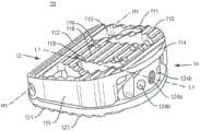
图1是根据本公开的原理的处于闭合配置的可扩展脊柱植入物的一个实施例的透视图;1 is a perspective view of one embodiment of an expandable spinal implant in a closed configuration in accordance with the principles of the present disclosure;
图2是根据本公开的原理的处于扩展配置的可扩展脊柱植入物的一个实施例的透视图;2 is a perspective view of one embodiment of an expandable spinal implant in an expanded configuration in accordance with the principles of the present disclosure;
图3是根据本公开的原理的处于闭合配置的可扩展脊柱植入物的一个实施例的侧视图;3 is a side view of one embodiment of an expandable spinal implant in a closed configuration in accordance with the principles of the present disclosure;
图4是根据本公开的原理的处于扩展配置的可扩展脊柱植入物的一个实施例的侧视图;4 is a side view of one embodiment of an expandable spinal implant in an expanded configuration in accordance with the principles of the present disclosure;
图5是根据本公开的原理的处于扩展配置的可扩展脊柱植入物的一个实施例的侧视图;5 is a side view of one embodiment of an expandable spinal implant in an expanded configuration in accordance with the principles of the present disclosure;
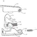
图6是根据本公开的原理的处于扩展配置的可扩展脊柱植入物的一个实施例的分解透视图;6 is an exploded perspective view of one embodiment of an expandable spinal implant in an expanded configuration in accordance with the principles of the present disclosure;
图7是根据本公开的原理的处于扩展配置的可扩展脊柱植入物的一个实施例的分解透视图;7 is an exploded perspective view of one embodiment of an expandable spinal implant in an expanded configuration in accordance with the principles of the present disclosure;
图8是根据本公开的原理的处于扩展配置的可扩展脊柱植入物的一个实施例的分解透视图;8 is an exploded perspective view of one embodiment of an expandable spinal implant in an expanded configuration in accordance with the principles of the present disclosure;
图9是根据本公开的原理的处于扩展配置的可扩展脊柱植入物的一个实施例的分解端视图;9 is an exploded end view of one embodiment of an expandable spinal implant in an expanded configuration in accordance with the principles of the present disclosure;
图10是根据本公开的原理的处于闭合配置的可扩展脊柱植入物的一个实施例的透视图;10 is a perspective view of one embodiment of an expandable spinal implant in a closed configuration in accordance with the principles of the present disclosure;
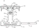
图11是根据本公开的原理的端板的一个实施例的内表面的透视图;11 is a perspective view of an inner surface of one embodiment of an end plate in accordance with principles of the present disclosure;
图12是根据本公开的原理的端板的一个实施例的外表面的透视图;12 is a perspective view of an outer surface of one embodiment of an end plate in accordance with principles of the present disclosure;
图13是根据本公开的原理的可扩展脊柱植入物和插入物的一个实施例的顶部剖视图;13 is a top cross-sectional view of one embodiment of an expandable spinal implant and insert in accordance with the principles of the present disclosure;
图14是根据本公开的原理的处于闭合配置的可扩展脊柱植入物的一个实施例的透视图;14 is a perspective view of one embodiment of an expandable spinal implant in a closed configuration in accordance with the principles of the present disclosure;
图15是根据本公开的原理的处于扩展配置的可扩展脊柱植入物的一个实施例的透视图;15 is a perspective view of one embodiment of an expandable spinal implant in an expanded configuration in accordance with the principles of the present disclosure;
图16是根据本公开的原理的处于闭合配置的可扩展脊柱植入物的一个实施例的侧视图;16 is a side view of one embodiment of an expandable spinal implant in a closed configuration in accordance with the principles of the present disclosure;
图17是根据本公开的原理的处于扩展配置的可扩展脊柱植入物的一个实施例的侧视图;17 is a side view of one embodiment of an expandable spinal implant in an expanded configuration in accordance with the principles of the present disclosure;
图18是根据本公开的原理的处于扩展配置的可扩展脊柱植入物的一个实施例的透视图;18 is a perspective view of one embodiment of an expandable spinal implant in an expanded configuration in accordance with the principles of the present disclosure;
图19是根据本公开的原理的处于扩展配置的可扩展脊柱植入物的一个实施例的透视图;19 is a perspective view of one embodiment of an expandable spinal implant in an expanded configuration in accordance with the principles of the present disclosure;
图20A-B是根据本公开的原理的端板的一个实施例的外表面的(A)透视图和(B)平面图;20A-B are (A) perspective and (B) plan views of the exterior surface of one embodiment of an end plate in accordance with principles of the present disclosure;
图21A-B是根据本公开的原理的端板的一个实施例的外表面的(A)透视图和(B)平面图;21A-B are (A) perspective and (B) plan views of the exterior surface of one embodiment of an end plate in accordance with principles of the present disclosure;
图22A-B是根据本公开的原理的端板的一个实施例的外表面的(A)透视图和(B)平面图;22A-B are (A) perspective and (B) plan views of the exterior surface of one embodiment of an end plate in accordance with principles of the present disclosure;
图23A-B是根据本公开的原理的端板的一个实施例的外表面的(A)透视图和(B)平面图;23A-B are (A) perspective and (B) plan views of the exterior surface of one embodiment of an end plate in accordance with principles of the present disclosure;
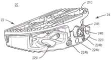
图24A-C描绘了根据本公开的原理的在不同位置(A、B、C)的可扩展脊柱植入物和插入物的一个实施例;24A-C depict one embodiment of an expandable spinal implant and insert in different positions (A, B, C) in accordance with the principles of the present disclosure;
图25是根据本公开的原理的如用于脊柱手术的可扩展脊柱植入物的一个实施例的俯视图;25 is a top view of one embodiment of an expandable spinal implant as used in spinal surgery in accordance with the principles of the present disclosure;
图26是根据本公开的原理的如用于脊柱手术的可扩展脊柱植入物的一个实施例的俯视图;26 is a top view of one embodiment of an expandable spinal implant as used in spinal surgery in accordance with the principles of the present disclosure;
图27是根据本公开的原理的处于闭合配置的可扩展脊柱植入物的一个实施例的侧视图;27 is a side view of one embodiment of an expandable spinal implant in a closed configuration in accordance with the principles of the present disclosure;
图28是根据本公开的原理的处于扩展配置的可扩展脊柱植入物的一个实施例的侧视图;28 is a side view of one embodiment of an expandable spinal implant in an expanded configuration in accordance with the principles of the present disclosure;
图29是根据本公开的原理的处于闭合配置的可扩展脊柱植入物的一个实施例的剖面侧视图;29 is a cross-sectional side view of one embodiment of an expandable spinal implant in a closed configuration in accordance with the principles of the present disclosure;
图30是根据本公开的原理的处于部分扩展配置的可扩展脊柱植入物的一个实施例的透视图;30 is a perspective view of one embodiment of an expandable spinal implant in a partially expanded configuration in accordance with the principles of the present disclosure;
图31A-B是根据本公开的原理的端板的一个实施例的外表面的(A)透视图和(B)平面图;31A-B are (A) perspective and (B) plan views of the exterior surface of one embodiment of an end plate in accordance with principles of the present disclosure;
图32A-B是根据本公开的原理的端板的一个实施例的外表面的(A)透视图和(B)平面图;32A-B are (A) perspective and (B) plan views of the exterior surface of one embodiment of an end plate in accordance with principles of the present disclosure;
图33A-B是根据本公开的原理的端板的一个实施例的外表面的(A)透视图和(B)平面图;33A-B are (A) perspective and (B) plan views of the exterior surface of one embodiment of an end plate in accordance with principles of the present disclosure;
图34A-B是根据本公开的原理的端板的一个实施例的外表面的(A)透视图和(B)平面图;34A-B are (A) perspective and (B) plan views of the exterior surface of one embodiment of an end plate in accordance with principles of the present disclosure;
图35是根据本公开的原理的扩展机构楔形件的一个实施例的端视图;35 is an end view of one embodiment of an expansion mechanism wedge in accordance with the principles of the present disclosure;
图36是根据本公开的原理的端板的一个实施例的俯视图;36 is a top view of one embodiment of an end plate in accordance with the principles of the present disclosure;
图37是根据本公开的原理的如用于脊柱手术的可扩展脊柱植入物的一个实施例的侧视图;37 is a side view of one embodiment of an expandable spinal implant as used in spinal surgery in accordance with the principles of the present disclosure;
图38是根据本公开的原理的如用于脊柱手术的可扩展脊柱植入物的一个实施例的侧视图;38 is a side view of one embodiment of an expandable spinal implant as used in spinal surgery in accordance with the principles of the present disclosure;
图39是根据本公开的原理的如用于脊柱手术的可扩展脊柱植入物的一个实施例的侧视图。39 is a side view of one embodiment of an expandable spinal implant as used in spinal surgery in accordance with the principles of the present disclosure.
图1-39中的共同编号方案(例如,1xx、2xx和3xx)指示植入物10、20和30的类似组件。The common numbering schemes (eg, 1xx, 2xx, and 3xx) in FIGS. 1-39 indicate similar components of
具体实施方式Detailed ways
在用于治疗肌肉骨骼病症的医疗装置方面,并且更具体地在可扩展外科手术植入物系统和/或用于治疗脊柱的一种或多种方法方面,讨论了所公开的外科手术系统和相关使用方法的示例性实施例,所述可扩展外科手术植入物系统可以包含可扩展脊柱植入物、插入器械、专用器械,如可扩展牵开器和使患者在不同方向上旋转和弯曲的脊柱外科手术台。The disclosed surgical systems and methods are discussed in terms of medical devices for treating musculoskeletal disorders, and more particularly in terms of expandable surgical implant systems and/or one or more methods for treating the spine. Exemplary embodiments of related methods of use, the expandable surgical implant system may include expandable spinal implants, insertion instruments, specialized instruments such as expandable retractors and rotating and flexing the patient in different directions spine surgery table.
在一些实施例中,本系统包含适合于从倾斜的、后外侧手术和/或经椎间孔腰椎椎体间融合术(有时称为TLIF手术)、直接后路(有时称为PLIF手术)、直接外侧入路(有时称为DLIF手术)、前路腰椎椎体间融合术(有时称为ALIF手术)或这些手术的变型插入的可扩展脊柱植入物,其中将本植入物插入到椎体间空间中,并且然后扩展以便赋予和/或增大脊柱的脊柱前凸和/或脊柱后凸曲线。In some embodiments, the present system comprises a system suitable for surgery from oblique, posterolateral, and/or transforaminal lumbar interbody fusion (sometimes referred to as TLIF procedures), direct posterior approaches (sometimes referred to as PLIF procedures), Expandable spinal implants inserted by direct lateral approach (sometimes called DLIF surgery), anterior lumbar interbody fusion (sometimes called ALIF surgery), or variations of these in the interbody space, and then expanded to impart and/or augment the lordotic and/or kyphotic curve of the spine.
在一些实施例中,所述脊柱植入物系统还可以用于通过在脊柱植入物被植入并扩展的选定水平处增加和/或恢复椎体之间的适当的脊柱前凸和/或脊柱后凸角度来恢复和/或赋予患者矢状平衡。在所描述的各个实施例中,所述脊柱植入物系统在用于治疗超出一级融合的脊柱病状的各种复杂脊柱手术中可以是有用的。此外,在封闭实施例中所描述的脊柱植入物系统也可以用作具有可扩展高度的融合装置,所述融合装置用于将植入物定制到特定椎体间椎间盘空间,以恢复邻近椎体之间的间隔并促进邻近椎体之间的脊柱融合。In some embodiments, the spinal implant system can also be used to increase and/or restore proper lordosis and/or lordosis between vertebral bodies at selected levels at which the spinal implant is implanted and expanded. or kyphosis angle to restore and/or impart sagittal balance to the patient. In the various embodiments described, the spinal implant system can be useful in a variety of complex spinal procedures for treating spinal conditions beyond primary fusion. In addition, the spinal implant system described in the closed embodiment can also be used as a fusion device with an expandable height for tailoring the implant to a specific interbody disc space to restore adjacent vertebrae Space between bodies and promote spinal fusion between adjacent vertebral bodies.
在一些实施例中,并且如上所述,本公开可以用于治疗脊柱病症,如退行性椎间盘疾病、椎间盘突出、骨质疏松症、脊椎滑脱、狭窄、脊柱侧凸和其它弯曲异常、脊柱后凸、肿瘤和骨折。在一些实施例中,本公开可以与其它骨骼和骨相关应用一起使用,所述应用包含与诊断和治疗相关的那些应用。在一些实施例中,所公开的脊柱植入物系统可以可替代地用于对处于俯卧或仰卧位置的患者进行外科手术治疗,和/或对脊柱采用各种外科手术方法,包含前路、后路、后正中入路、直接外侧入路、后外侧斜入路和/或前外侧斜入路方法,以及在其它身体区域中。本公开还可以可替代地与用于治疗脊柱的腰椎、颈椎、胸椎、骶骨和骨盆区域的手术一起使用。本公开的脊柱植入物系统还可以用于动物、骨模型和其它非生物基质上,例如,在训练、测试和演示中。In some embodiments, and as described above, the present disclosure may be used to treat spinal disorders such as degenerative disc disease, disc herniation, osteoporosis, spondylolisthesis, stenosis, scoliosis and other curvature abnormalities, kyphosis , tumors and fractures. In some embodiments, the present disclosure may be used with other bone and bone-related applications, including those related to diagnosis and therapy. In some embodiments, the disclosed spinal implant systems may alternatively be used for surgical treatment of patients in prone or supine positions, and/or for various surgical approaches to the spine, including anterior, posterior approach, posterior median approach, direct lateral approach, posterolateral oblique approach, and/or anterolateral oblique approach approaches, and in other body regions. The present disclosure may also alternatively be used with procedures for treating the lumbar, cervical, thoracic, sacral, and pelvic regions of the spine. The spinal implant systems of the present disclosure can also be used on animals, bone models, and other non-biological substrates, eg, in training, testing, and demonstrations.
可以通过参考结合附图的实施例的以下详细描述更容易地理解本公开,所述附图形成本公开的一部分。应当理解,本申请不限于本文描述和/或示出的具体装置、方法、条件或参数,并且本文使用的术语仅出于通过实例描述特定实施例的目的,并不旨在是限制性的。在一些实施例中,如在说明书中使用并且包含所附权利要求书,单数形式“一种(a)”,“一个(an)”和“所述(the)”包含复数指代物,并且除非上下文另有明确规定,否则对特定数值的引用包含至少所述特定值。在本文中范围可以表示为从“约(about)”或“大约(approximately)”一个特定值和/或到“约”或“大约”另一个特定值。当表示这样的范围时,另一个实施例包含从一个特定值和/或到另一个特定值。类似地,当通过使用先行词“约”来将值表示为近似值时,应该理解,所述特定值形成了另一个实施例。还应当理解,所有空间参考,例如水平、垂直、顶部、上部、下部、底部、左侧和右侧,仅用于说明目的,并且可以在本公开的范围内变化。例如,参考“上部”和“下部”是相对的并且仅在上下文中用于另一个,并且不一定是“上方”和“下方”。通常,不同方面或组件的类似空间参考(例如,端板的“第一端部”和楔形件的“第一端部”)指示类似的空间朝向和/或定位,即每个“第一端部”位于或朝着所述装置的同一端部。进一步地,本文中各种空间术语的使用不应当被解释为限制植入物相对于脊柱中的位置的各种插入技术或朝向。The present disclosure may be more readily understood by reference to the following detailed description of the embodiments taken in conjunction with the accompanying drawings, which form a part hereof. It is to be understood that this application is not limited to the specific devices, methods, conditions or parameters described and/or illustrated herein and that the terminology used herein is for the purpose of describing particular embodiments by way of example only and is not intended to be limiting. In some embodiments, as used in this specification and including the appended claims, the singular forms "a (a)," "an (an)," and "the (the)" include plural referents, and unless The context clearly dictates otherwise, and references to a particular value otherwise include at least that particular value. Ranges may be expressed herein as from "about" or "approximately" one particular value and/or to "about" or "approximately" another particular value. When expressing such a range, another embodiment encompasses from one particular value and/or to another particular value. Similarly, when values are expressed as approximations, by use of the antecedent "about," it will be understood that the particular value forms another embodiment. It should also be understood that all spatial references, such as horizontal, vertical, top, upper, lower, bottom, left and right, are for illustrative purposes only and may vary within the scope of the present disclosure. For example, references to "upper" and "lower" are relative and only used in the context of one another, and not necessarily "above" and "below." Typically, similar spatial references to different aspects or components (eg, the "first end" of the end plate and the "first end" of the wedge) indicate similar spatial orientations and/or orientations, that is, each "first end" part" at or towards the same end of the device. Further, the use of various spatial terms herein should not be construed as limiting the various insertion techniques or orientations of the implant relative to the position in the spine.
如在说明书中使用并且包含所附权利要求书,疾病或病状的“治疗(treating/treatment)”是指执行手术,所述手术可以包含向患者(人、正常的或非正常的人或其它哺乳动物)施用一种或多种药物、生物制品、骨移植物(例如包含同种异体移植物、自体移植物、异种移植物)或骨生长促进性材料、采用可植入装置和/或采用治疗疾病的器械,例如用于去除凸出部分或椎间盘突出和/或骨刺的微型椎间盘切除器械,以努力缓解疾病或病状的体征或症状。缓解可以发生在疾病或病状的体征或症状出现之前,以及发生在其出现之后。因此,治疗或治疗包含预防或预防疾病或不期望病状(例如,预防疾病在可能倾向于患有疾病但尚未被诊断为患有疾病的患者身上发生)。此外,治疗或治疗不需要体征或症状的完全缓解,不需要治愈,并且具体包含对患者仅具有边际效果的手术。治疗可以包含抑制疾病,例如阻止其发展,或缓解疾病,例如引起疾病消退。例如,治疗可以包含减少急性或慢性炎症;缓解疼痛,并减轻和诱发新韧带、骨和其它组织的再生;作为外科手术中的辅助手段;和/或任何修复手术。此外,如在说明书中使用并且包含所附权利要求书,术语“组织”包含软组织、韧带、腱、软骨和/或骨,除非另有特别说明。如本文所使用的术语“骨生长促进性材料”可以包含但不限于:各种形式和组成(包含但不限于颗粒性骨移植物)的骨移植物(自体移植物、同种异体移植物、异种移植物);骨诱导材料,如骨形态发生蛋白(BMP)(包含但不限于可从美敦力(Medtronic)获得的

以下讨论包含对包含一个或多个脊柱植入物、相关组件的外科手术系统和采用根据本公开的原理的外科手术系统的方法的描述。公开了各种替代性实施例,并且每个实施例的单独组件可以与其它实施例一起使用。详细参考在附图中展示的本公开的示例性实施例。转到图1-36,展示了外科手术系统的组件,例如可扩展脊柱植入物10、20和30。The following discussion contains descriptions of surgical systems that include one or more spinal implants, related components, and methods of employing surgical systems in accordance with the principles of the present disclosure. Various alternative embodiments are disclosed, and individual components of each embodiment may be used with other embodiments. Reference is made in detail to the exemplary embodiments of the present disclosure which are illustrated in the accompanying drawings. 1-36, components of a surgical system, such as expandable
本文所描述的可扩展脊柱植入物系统的组件可以由适合于医疗应用的生物学上可接受的材料(包含金属、合成聚合物、陶瓷和骨材料和/或其复合材料)制造。例如,可扩展脊柱植入物系统的组件可以单独地或共同地由以下材料制造:如不锈钢合金、工业纯钛、钛合金、5级钛、超弹性钛合金、钴-铬合金、不锈钢合金、超弹性金属合金(例如,镍钛诺、超弹性塑料金属,如GUM
脊柱植入物系统的各种组件可以由材料复合材料形成或构造,包含但不限于上述材料,以实现如强度、刚度、弹性、顺从性、生物力学性能、耐久性和射线可透性或成像偏好等各种期望的特性。可扩展脊柱植入物系统的组件还可以单独地或共同地由异质材料制造,如上述材料中的两种或更多种的组合。可扩展脊柱植入物系统的组件可以被整体形成、一体连接或包含紧固元件和/或器械,如本文所述。例如,在一些实施例中,可扩展脊柱植入物系统可以包括可扩展脊柱植入物10、20、30,所述可扩展脊柱植入物包括具有选择性放置在植入物中的射线可透过的标记物(如钽销和/或钉)的PEEK和/或钛结构,以便在可扩展脊柱植入物10、20、30被放置在脊柱中时向执业医师提供放置和/或大小信息。可扩展脊柱植入物系统的组件可以使用各种减材和增材制造技术来形成,包含但不限于机加工、铣削、挤出、模制、3D打印、烧结、涂层、气相沉积和激光/光束熔化。此外,可扩展脊柱植入物系统的各种组件可以用各种增材或涂层涂覆或处理,以改善生物相容性、骨生长促进或其它特征。例如,端板110、120、210、220、310、320可以选择性地涂覆有骨生长促进性表面处理或骨上生长促进性表面处理(bone ongrowth promoting surface treatment),所述表面处理可以包含但不限于:钛涂层(固体、多孔或纹理化)、羟基磷灰石涂层或钛板(固体、多孔或纹理化)。The various components of the spinal implant system may be formed or constructed from composite materials of materials, including but not limited to those described above, to achieve properties such as strength, stiffness, elasticity, compliance, biomechanical properties, durability, and radiolucency or imaging preferences and other desired characteristics. The components of the expandable spinal implant system can also be fabricated individually or collectively from heterogeneous materials, such as a combination of two or more of the aforementioned materials. The components of the expandable spinal implant system may be integrally formed, integrally connected, or contain fastening elements and/or instruments, as described herein. For example, in some embodiments, an expandable spinal implant system can include expandable
可扩展脊柱植入物系统可以例如与包含经皮技术、微开放和开放外科手术技术的微创手术一起使用,以在患者体内的外科手术部位处(例如,脊柱的区段)递送和引入仪器和/或一个或多个脊柱植入物。在一些实施例中,可扩展脊柱植入物系统可以与如本文所述的外科手术和/或例如椎体切除术、椎间盘切除术、融合术和/或固定术治疗一起使用,所述治疗采用脊柱植入物来恢复椎骨的机械支撑功能。在一些实施例中,可扩展脊柱植入物系统可以与外科手术方法一起使用,所述方法包含但不限于:前路腰椎椎体间融合术(ALIF)、后路腰椎椎体间融合术(PLIF)、斜腰椎椎体间融合术、经椎间孔腰椎椎体间融合术(TLIF)、各种类型的前路融合术手术以及脊柱的任何部分(例如,骶骨、腰椎、胸椎和颈椎)中的任何融合术手术。The expandable spinal implant system can be used, for example, with minimally invasive procedures including percutaneous techniques, micro-open and open surgical techniques, to deliver and introduce instruments at a surgical site (eg, a segment of the spine) within a patient's body and/or one or more spinal implants. In some embodiments, the expandable spinal implant system may be used with surgical procedures as described herein and/or treatments such as vertebrectomy, discectomy, fusion, and/or fixation employing Spinal implants to restore the mechanical support function of the vertebrae. In some embodiments, the expandable spinal implant system may be used with surgical methods including, but not limited to: anterior lumbar interbody fusion (ALIF), posterior lumbar interbody fusion ( PLIF), oblique lumbar interbody fusion, transforaminal lumbar interbody fusion (TLIF), various types of anterior fusion procedures, and any part of the spine (eg, sacrum, lumbar, thoracic, and cervical) any fusion surgery.
通常在图1-36中,示出了可扩展脊柱植入物10、20和30的三个示例性实施例(植入物10在示例性图1-13中突出显示,植入物20在示例性图14-26中突出显示,并且植入物30在示例性图27-36中突出显示)。可扩展脊柱植入物10、20和30可以包括通过铰链机构可操作地接合的第一端板和第二端板,所述铰链机构通过垂直于铰链接头(hinge joint)的轴线驱动的楔形件机构使端板相对于彼此前凸地(lordotically)或成角度地扩展。在一些实施例中,楔形件驱动方向可以被朝向成与铰链轴线成0与90度之间的斜角。在一些实施例中,当楔形件机构被朝着所述铰链驱动时,第一和第二端板可以前凸地扩展。在其它实施例中,当楔形件机构被驱动远离所述铰链时,第一和第二端板可以前凸地扩展。Generally in Figures 1-36, three exemplary embodiments of expandable
如图1-13所示,可扩展脊柱植入物10被配置成插入邻近椎体之间的椎间盘空间中。植入物10包含第一端部12和第二端部14,所述第一端部和第二端部限定其间的中间纵向轴线L1-L1。在一些实施例中,可扩展脊柱植入物10包括第一端板110和第二端板120。第一端板110包含第一端部112、第二端部114、两个相对的侧表面115、内表面116和外表面118,所述两个相对的侧表面从第一端板的第一端部112延伸到第一端板的第二端部114的一部分,并且其中第一端板位于所述两个相对的侧表面之间。第二端板120包含第一端部122、第二端部124、两个相对的侧表面125、内表面126和外表面128,所述两个相对的侧表面从第二端板的第一端部122延伸到第二端板的第二端部124的一部分,并且其中第二端板位于所述两个相对的侧表面之间。在一个实施例中,端板110、120包含突出部111、121,所述突出部被配置成接合邻近椎体(未示出)的端板的表面。突出部111、121可以包括各种抗迁移、抗排出和/或骨整合特征,包含但不限于:脊、齿、孔和涂层(包含但不限于多孔钛涂层,如可从美敦力获得的Capstone PTCTM植入物上提供的涂层)。端板110、120可以进一步包括限定在其中的至少一个开口113、123,所述至少一个开口被配置成允许骨生长材料被包装、放置或装载到植入物10中。As shown in Figures 1-13, the expandable
通常参考图1-12,端板110、120可以通过位于第一端部112和122附近或其上的铰链机构可操作地接合。例如,如图7所示,第一端板110的第一端部112可以包括第一和第二铰链突出部117,所述第一和第二铰链突出部沿着第一端部112的长度的垂直于中间纵向轴线L1-L1的至少一部分延伸。在一些实施例中,第一和第二铰链突出部是圆柱形的,并且从侧向侧表面115朝着中间纵向轴线L1-L1延伸,并且进一步包括穿过所述第一和第二铰链突出部延伸的管腔117b。第二端板120的第一端部122还可以包括铰链突出部127。在一些实施例中,铰链突出部127是圆柱形的,并且沿着第一端部122侧向延伸,并且进一步包括穿过所述铰链突出部延伸的管腔127b。第一和第二铰链突出部117的管腔和铰链突出部127的管腔可以沿着铰链轴线H1-H1同轴对准。销130可以安置在铰链突出部117、127的管腔内,以将第一端板110可枢转地接合到第二端板120。以这种方式,第一端板110可以远离第二端板120铰接和/或旋转,使得第二端部114与124之间的距离沿着径向弧R增加。虽然在一些图示实施例中示出了简单的销和管腔铰链,但是应当理解,还可以使用其它类型的铰链和/或连接机构来可操作地接合植入物的端板110、120。例如,在一些实施例中,可以利用“活动铰链”,其中端板110、120至少部分地一体形成在铰接点处,但是具有允许端板110、120绕铰链连接旋转的切口或挠曲点。端板110、120可以以许多不同的方式可操作地接合,包含但不限于:一体的连接、可分离的连接、使用紧固件或粘合剂的机械地固定连接、可释放的连接(包含但不限于键槽和部分打开的铰链)以及其它连接类型。在一些实施例中,端板110、120可以使用增材制造技术一体形成(如3D打印、烧结激光/光束熔化、铸造、挤出或使用来自一种或多种原料的减材制造技术以一体的形式机加工。Referring generally to FIGS. 1-12 , the
如本文所述,植入物10可以包含用于扩展端板110、120以增加植入物10的脊柱前凸角度R的扩展机构。在一些实施例中,植入物10的扩展机构包含具有纵向轴线E3-E3的杆组合件140,所述杆组合件包括杆142、固定销143和安装在第一端板110与第二端板120之间的植入物内的楔形件150。楔形件150可以包括第一端部152、第二端部154、上表面158、下表面156以及在第一端部与第二端部之间延伸的相对的侧面155。楔形件150可以进一步包括在第一端部与第二端部之间的孔口151。杆组合件140可以包括安置在孔口151内的杆142。在一些实施例中,杆142包括螺纹外表面141,所述螺纹外表面被配置成与楔形件150的孔口151的互补内螺纹表面接合,使得当杆142相对于楔形件150旋转时,楔形件150在植入物10的第一端部与第二端部之间沿着杆142向前和向后行进。在一些实施例中,杆142和固定销143可以一体形成,并且在此类实施例中,应当理解,一体的杆组合件140可以在下文的讨论中与杆142互换。As described herein, the
植入物10的扩展机构可以与第一端板110或第二端板120可操作地接合。在一些实施例中,植入物10的扩展机构固定到第二端板120。第二端板120的铰链突出部127可以包括穿过铰链突出部127的壁并且总体上垂直于穿过所述铰链突出部的管腔127b的第一端部孔口127a。第二端板120的第二端部124可以进一步包括穿过其中的孔口124a。在一些实施例中,孔口127a和124a通常是同轴的。杆组合件140的一个端部或两个端部可以沿着第一端部122固定在第二端部124的孔口124a和铰链突出部127的第一孔口127a中的一个或两个内,以可操作地将植入物10的扩展机构与第二端板120接合。在所示的实施例中,杆142的第二端部固定在孔口124a内,并且穿过孔口127a安置的圆柱形固定销143同轴接合杆142的端部,以进一步将扩展机构固定在植入物10内。安置在铰链突出部117、127的管腔内的销130可以包含切口部分131,以允许杆142和/或圆柱形固定销143被安置成穿过孔口127a。在一些实施例中,杆组合件140被安置成使得纵向轴线E1-E1基本上平行于植入物10的中间纵向轴线L1-L1(即,垂直于铰链轴线H1-H1)。在一些实施例中,孔口124a和127a可以对准,使得杆组合件140被安置成使得纵向轴线E1-E1与植入物10的中间纵向轴线L1-L1成斜角(例如,在零与90度之间)。The expansion mechanism of the
杆142可以在孔口124a、127a内相对于植入物10是可旋转的。第一端板110的内表面116可以包括远离第一端板110的内表面116延伸的导向壁116a。在一些实施例中,导向壁116a远离第一端板110的内表面116垂直地延伸。在一些实施例中,导向壁116a被朝向成基本上平行于杆142的纵向轴线L,并且被安置成彼此相隔宽度W。在一些实施例中,宽度W基本上类似于楔形件150的宽度,其中楔形件150被安置在导向壁116a之间。楔形件150的侧向侧155与导向壁116a接合,从而防止楔形件150相对于植入物10旋转。以这种方式,当杆142旋转时,螺纹表面141、151之间的相互作用使得楔形件150沿着杆142的纵向轴线L平移。The
楔形件150可以包含上表面158,所述上表面被配置成与第一端板110的内表面116接合,并且当楔形件150朝着植入物10的第一端部12移动时,使第一端板110远离第二端板120前凸地扩展。例如,上表面158可以是倾斜的或楔形的,并且适合于推动第一端板110内部上的互补倾斜的或波状外形的表面,以便在楔形件150沿着杆142朝着第一端部12前进时,使第一端板140逐渐远离第二端板150移动。在所描绘的实施例中,第一端板110的内表面116可以进一步包括斜坡116b,以接合楔形件150的上表面158。在一些实施例中,扩展机构可以被配置成使得楔形件150的下表面156接合第二端板120的内表面126,可替代地或另外地,接合第一端板110的内表面116的上表面158。在一些实施例中,扩展机构可以被配置成当楔形件150朝着植入物10的第二端部14移动时,使植入物10前凸地扩展。The
在一些实施例中,斜坡机构158/116b可以与一个或多个成对的侧柱155a和通道116c系统配合,以优化植入物10的打开和/或扩展。导向壁116a可以包括侧通道116c。通道116c可以是成角度的或部分成角度的,以提供用于在楔形件150沿着杆142朝着植入物10的第一端部12处的铰链前进时辅助植入物10的扩展的机构。楔形件150可以包括与通道116c接合的一个或多个侧柱155a以提供扩展机构,所述扩展机构被配置成当楔形件150朝着植入物10的第一端部12移动时,推动第一端板110远离第二端板120。柱155a和通道116c机构还可以帮助使植入物10的扩展基本上可逆,使得当楔形件150远离铰链移动时,侧柱155a在侧通道116c中在第二方向上移动,以使第一端板110朝着第二端板120收缩(这可以导致植入物10返回到图1总体所示的闭合或未扩展配置)。这种可逆特征与杆142与楔形件150之间的螺纹相互作用结合,使得植入物10能够在基本上无限可调节运动范围(仅由通道116c的长度界定)内递增地扩展或收缩。可以调节通道116c的长度和朝向以确定脊柱前凸扩展的量。在一些实施例中,扩展机构的设计(包含通道116c的长度和朝向)被配置成在楔形件150朝着铰链组合件移动时,允许高达30度、35度、40度、45度、50度或60度或从0度到60度的这些量之间或更多的任何量的脊柱前凸扩展。In some embodiments,
在一些实施例中,可以使用各种设计来优化楔形件150与第一端板110的相互作用。这种配置可以包含但不限于:具有不同角度的连续斜坡或锥形表面;通向更高角度的连续斜坡或锥形表面的浅角度的连续斜坡或锥形表面,以及其它打开机构(如上述的侧柱155a和通道116c系统,所述侧柱和系统可以结合以辅助斜坡扩展植入物10)。In some embodiments, various designs may be used to optimize the interaction of the
如上所述,植入物10的扩展机构140、150固定到第二端板120,使得当楔形件150朝着植入物10的第一端部12移动时,第一端板110被推动远离扩展机构140、150和第二端板120。在一些实施例中,仅杆组合件140的第一端部145可以固定到第一端板110和/或第二端板120,使得在植入物10扩展或收缩时,杆组合件140的第二端部146可以相对于端板110、120移动。在此类实施例中,楔形件150的下表面156可以是倾斜的或楔形的,并且适合于推动第二端板120内部上的互补倾斜的或波状外形的表面,以便在楔形件150沿着杆142前进时,使端板110、120逐渐远离彼此移动。第二端板120的内表面126包括斜坡以接合楔形件150的下表面156,和/或可以包括导向壁,其中通道安置在所述导向壁中,以接合从楔形件150延伸的侧柱,类似于上述针对楔形件150的上表面158与第一端板110的内表面116的相互作用描述的那些。在一些实施例中,可以使用各种设计来优化楔形件150与端板110、120的相互作用。这种配置可以包含但不限于:具有不同角度的连续斜坡或锥形表面;通向更高角度的连续斜坡或锥形表面的浅角度的连续斜坡或锥形表面,以及其它打开机构(如上述的侧柱155a和通道116c系统,所述侧柱和系统可以结合以辅助斜坡扩展植入物10)。As described above, the
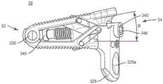
随着楔形件150朝着铰链移动,所述机构失去了机械优势,因为楔形件与铰链接头之间的杠杆臂在扩展期间减小。这为使用植入物10的执业医师提供了增加的力反馈,从而给予执业医师更好的解剖学约束的感觉。为了补充扩展力,植入物10可以与操纵脊柱的其它外科手术器械特别配对或一起使用。这些外科手术器械包含例如外科手术台、患者定位框架等,其操纵患者,并且可以例如通过在不同方向上弯曲患者的脊柱并调节患者的朝向以方便或促进进入一个或多个脊柱外科手术位置来进一步促进和/或调节进入一个或多个椎间盘空间。示例性外科手术台、患者定位框架等以及使用其的相关方法包含在例如美国专利申请序列号15/239,239、15/239,256、15/337,157、15/638,802、15/639,080、15/672,005和15/674,456中描述的那些,所有所述美国专利申请通过引用整体并入本文。As the
在一些实施例中,杆142的第二端部146可以包括接口144,所述接口被配置成由驱动轴(未示出)可操作地接合以使杆142旋转。杆接口144可以包括驱动插座,所述驱动插座被配置成与驱动轴的植入物接合端部配合。驱动器轴与杆接口144之间的驱动连接可以包括各种驱动接口,包含但不限于:多叶驱动器;六叶驱动器;十字驱动器或菲利普斯头驱动器(Phillips head drive);直线或“平头”驱动器;方形或其它多边形驱动器;和/或其组合。在其它实施例中,杆组合件140的第一端部145(通过杆142或固定销143)可以进一步包括接口,所述接口被配置成由驱动轴可操作地接合以使杆组合件140旋转。以这种方式,本公开的植入物可以从前路入路/斜入路和后路入路两者扩展。In some embodiments, the
在一些实施例中,植入物10可以进一步包括椎体端板接合组件170,所述椎体端板接合组件被配置成在植入物10扩展时接合椎体端板。在一些实施例中,椎体端板接合组件170可以是爪形或钩形的。可以设想,椎体端板接合组件170可以包括适合于接合椎体端板的各种配置,以减小或防止装置从椎间空间的潜在迁移或排出。如图1和3所示,当植入物10处于塌缩、闭合或未扩展状态时,椎体端板接合组件170可以在装置内缩回,以允许容易地插入到椎间盘空间中。如图2和4所示,在植入物10扩展时,并且椎体端板接合组件170从植入物10突出并接合椎体端板,以减小装置的潜在迁移。在图1-12所描绘的实施例中,椎体端板接合组件170安装在导向壁116a之间,并且被安置成邻近楔形件150的上表面158。导向壁116a可以各自包括孔口171,销172被安置成穿过所述孔口以将椎体端板接合组件170安装到第一端板110。在一些实施例中,椎体端板接合组件170可至少部分地绕销172旋转。椎体端板接合组件170可以成形为在楔形件150朝着植入物10的第一端部12移动时接合楔形件150的上表面158,使得齿170部分地绕销172旋转并且突出穿过第一端板110的孔口119并接合椎体端板。在楔形件150远离第一端部12移动时,椎体端板接合组件170的单独部分可以接合楔形件150的上表面158,以将椎体端板接合组件170缩回到植入物10的内部中。在替代性实施例(未示出)中,椎体端板接合组件170可以结合到活塞中。在植入物10扩展时,楔形件150将接合活塞。在另一个实施例(未示出)中,椎体端板接合组件170可以安装在旋转齿轮上。在楔形件150使植入物10扩展时,楔形件150上的配对齿轮将接合旋转齿轮并且使椎体端板接合组件170旋转成与椎体端板接合。在另一个实施例(未示出)中,杆组合件140可以通过例如螺纹外表面141直接接合椎体端板接合组件170。In some embodiments, the
尽管图1-12描绘了仅从第一端板110突出的椎体端板接合组件170,但是其它实施例可以包含从第二端板120或从端板110、120两者突出的椎体端板接合组件。在一些实施例中,植入物10可以通过穿过端板110或120的内表面与外表面之间的孔口放置的固有螺钉(intrinsic screw)来固定(如针对图18、19中的植入物20所描绘的和下文所讨论的)。这些螺钉可以进一步由外部锁定机构(如垫圈、弹簧、板或盖)保持在适当位置,所述外部锁定机构覆盖或推动螺钉顶部或头部的至少一部分。在其它实施例中,所述螺钉可以通过过盈配合在螺钉孔中和/或通过所述螺钉孔中的特征而被保持在适当位置,从而向螺钉顶部或头部添加摩擦配合和/或保持力。在其它实施例中,植入物10可以通过端板110或120上的集成凸片(integrated tab)(如针对图30中的植入物30所描绘的和如下文所讨论的)或可以覆盖椎间植入物的一部分的可分离的板来固定。Although FIGS. 1-12 depict the vertebral body
图13示出了根据一个实施例的与插入器械40一起使用以形成可扩展脊柱植入物系统的植入物10。如图13总体所示,所述系统可以包括插入器械40,所述插入器械包括附接套管410和驱动器套管420。插入器械40可以进一步包括可移除地并且可旋转地安置在附接套管410内的附接轴411和可移除地并且可旋转地安置在驱动器套管420内的驱动轴421。附接轴411的植入物接合端部可以包括螺纹外表面。插入器械40可以进一步包括驱动接合组件422,所述驱动接合组件通过例如u形接头423连接到驱动轴421的端部。Figure 13 illustrates
所述系统还可以进一步包括可扩展脊柱植入物10,所述可扩展脊柱植入物被配置成使用各种机构与插入器械40可操作地接合。如本文所述,植入物10的第二端部14可以被配置成收容插入器械40的工具端部,以操纵可扩展植入物10。在一个实施例中,植入物10的第二端板120的第二端部124包括邻近孔口124a侧向安置的附接孔口124b。这些孔口124b可以根据特定外科手术技术的需要相对于植入物10的中间纵向轴线L1-L1间隔开和成角度。在一些实施例中,孔口124b可以平行于植入物10的中间纵向轴线L1-L1。在所描绘的实施例中,孔口124b的轴线相对于中间纵向轴线L1-L1成大约15度的角度。孔口124b可以包括用于接合附接轴411的植入物接合端部上的螺纹外表面的内螺纹表面。在其它实施例中,附接轴411的植入物接合端部可以与由端板110、120中的一者或两者限定的凸片或狭槽相互作用。附接轴411可以同轴地放置在附接套管410内,并且使用附接套管的手动端部(未示出)在其中旋转。附接轴411的手动端部可以包括带键或刻面表面,所述带键或刻面表面被配置成用于与快速释放手柄(未示出)或用于使附接轴411旋转的动力驱动器(未示出)接合。The system may also further include an expandable
在一些实施例中,如图13所示,杆142的接口144可以被配置成由驱动轴421的植入物接合端部可操作地接合,以沿着杆142平移(例如,通过螺纹旋转)楔形件150。驱动轴421可以同轴地放置在驱动套管420内,并且可以使用驱动轴421的手动端部(未示出)在其中旋转。驱动轴421的手动端部可以包括带键或刻面表面,所述带键或刻面表面被配置成用于与快速释放手柄(未示出)或用于使驱动轴421旋转的动力驱动器(未示出)接合。此外,杆接口144可以包括驱动插座,所述驱动插座被配置成与驱动轴421的植入物接合端部配合。驱动轴421与杆接口144之间的驱动连接可以包括各种驱动接口,包含但不限于:多叶驱动器;六叶驱动器;十字驱动器或菲利普斯头驱动器(Phillips head drive);直线或“平头”驱动器;方形或其它多边形驱动器;和/或其组合。在一些实施例中,驱动轴421通过驱动接合组件422接合杆接口144,所述驱动接合组件通过例如u形接头423连接到驱动轴421的端部。u形接头423允许驱动轴421与杆组合件140之间成角度。In some embodiments, as shown in FIG. 13 , the
图14-26示出了根据本公开的植入物20实施例的各种配置。植入物20在构造上总体类似于上述植入物10和下述植入物30,并且包括第一端板210和第二端板220以及扩展机构,所述第一端板和第二端板沿着植入物第一端部22通过铰链机构可操作地彼此接合,所述扩展机构包括杆组合件240和安置在所述第一端板和第二端板之间的楔形件250。第一端板210包含第一端部212、第二端部214、相对的侧表面215、内表面216和外表面218,所述相对的侧表面从第一端板的第一端部212延伸到第一端板的第二端部214的一部分,并且其中第一端板位于所述相对的侧表面之间。第二端板220包含第一端部222、第二端部224、两个相对的侧表面225、内表面226和外表面228,所述两个相对的侧表面从第二端板的第一端部222延伸到第二端板的第二端部224的一部分,并且其中第二端板位于所述两个相对的侧表面之间。在一个实施例中,端板210、220包含突出部211、221,所述突出部被配置成接合邻近椎体(未示出)的端板的表面。突出部211、221可以包括各种抗迁移、抗排出和/或骨整合特征,包含但不限于:脊、齿、孔和涂层(包含但不限于多孔钛涂层,如可从美敦力获得的Capstone PTCTM植入物上提供的涂层)。端板210、220可以进一步包括限定在其中的至少一个开口213、223,所述至少一个开口被配置成允许骨生长材料被包装、放置或装载到植入物20中。14-26 illustrate various configurations of
端板210、220可以通过位于第一端部212和222附近或其上的铰链机构可操作地接合。例如,第一端板210的第一端部212可以包括第一和第二铰链突出部217,所述第一和第二铰链突出部沿着第一端部212的长度的垂直于中间纵向轴线L2-L2的至少一部分延伸。在一些实施例中,第一和第二铰链突出部是圆柱形的,并且从侧向侧表面215朝着中间纵向轴线L2-L2延伸,并且进一步包括穿过所述第一和第二铰链突出部延伸的管腔217b。第二端板220的第一端部222还可以包括铰链突出部227。在一些实施例中,铰链突出部227是圆柱形的,并且沿着第一端部122侧向延伸,并且进一步包括穿过所述铰链突出部延伸的管腔227b。铰链突出部217、227的管腔217b、227b可以沿着铰链轴线H2-H2同轴对准。销230可以安置在铰链突出部217、227的管腔217b、227b内,以将第一端板210可枢转地接合到第二端板220。The
扩展机构240、250被设计成在楔形件250沿着杆组合件240朝着植入物20的第二端部24平移时,使第一端板210和第二端板220远离彼此扩展。杆组合件240可以一体形成,或可以由多个组件形成,以便例如易于制造和/或组装,如同上文的杆组合件140。杆组合件240可以在杆第一端部245处固定到第一端板210和/或第二端板220,使得在植入物20扩展或收缩时(即,移动到打开或闭合的配置中),第二杆端部246可以相对于端板210、220移动。在一些实施例中,扩展机构240、250的纵向轴线E2-E2可以沿着植入物20的中间纵向轴线L2-L2对准。在其它实施例中,扩展机构240、250的纵向轴线E2-E2可以从植入物20的中间纵向轴线L2-L2偏移,如图25所描绘的,和/或可以与中间纵向轴线L2-L2倾斜地成角度,如图26所描绘的。如上文针对植入物10所描述的,杆组合件240的第二端部246可以包括接口244,所述接口被配置成由驱动轴(未示出)可操作地接合,以使杆组合件240旋转。杆接口244可以包括驱动插座,所述驱动插座被配置成与驱动轴的植入物接合端部配合。驱动轴与杆接口244之间的驱动连接可以包括各种驱动接口,包含但不限于:多叶驱动器;六叶驱动器;十字驱动器或菲利普斯头驱动器(Phillips head drive);直线或“平头”驱动器;方形或其它多边形驱动器;和/或其组合。在其它实施例中,杆组合件240的第一端部245可以进一步包括接口,所述接口被配置成由驱动轴可操作地接合以使杆组合件240旋转。以这种方式,本公开的植入物可以从前路入路/斜入路和后路入路两者扩展,如图25和26所描绘的。The
在一些实施例中,楔形件250的上表面258和下表面256可以是倾斜的或楔形的,并且适合于推动端板210、220内部上的互补倾斜的或波状外形的表面,以便在楔形件250沿着杆组合件240朝着植入物20的第二端部24前进时,使端板210、220逐渐远离彼此移动。在一些实施例中,可以使用各种设计来优化楔形件250与端板210、220的相互作用。这种配置可以包含但不限于:具有不同角度的连续斜坡或锥形表面;通向更高角度的连续斜坡或锥形表面的浅角度的连续斜坡或锥形表面,以及其它打开机构(如侧柱和通道系统)。如图21和23所示,端板210、220的内表面216、226可以包括导向壁216a、226a,其中侧通道216c、226c安置在所述导向壁中,以接合从楔形件250延伸的侧柱255a。由柱255a和通道216c、226c提供的机构还可以帮助使植入物20的扩展基本上可逆。例如,在所描绘的实施例中,当楔形件250朝着植入物20的第二端部24移动时,柱255a在通道216c、226c中在第一方向上移动,以使第一端板210和第二端板220远离彼此扩展(这可以导致植入物20打开到图15总体所示的扩展配置),并且当楔形件250朝着植入物20的第一端部22移动时,柱255a在通道216c、226c中在第二方向上移动,以使第一端板210和第二端板220朝着彼此收缩(这可以导致植入物20返回到图14总体所示的闭合或未扩展配置)。这种可逆特征与杆组合件240与楔形件250之间的螺纹相互作用结合,使得植入物20能够在基本上无限可调节运动范围(仅由通道216c、226c的长度界定)内递增地扩展或收缩。可以调节扩展机构的设计(包含通道216c、226c的长度和朝向)以确定脊柱前凸扩展的量。在一些实施例中,在处于塌缩/闭合状态时,植入物20提供12度的脊柱前凸矫正,并且在楔形件250朝着植入物20的第二端部24移动时,所述植入物能够提供高达32度、60度或更多的脊柱前凸扩展或高脊柱前凸扩展。In some embodiments, the
在所描绘的实施例中,第二端板220可以包括孔口229,一个或多个螺钉270可以被安置成穿过所述孔口,以将端板220固定在椎间空间内。螺钉270可以包括与孔口229的内表面接合的螺纹外表面271,所述孔口也可以是螺纹的。螺纹外表面271与孔口229的内表面之间的接合可以通过螺距锁定、主/次锁定(major/minor lock)或任何其它螺纹/螺距接口进行。In the depicted embodiment, the
在一些实施例中,植入物20的第二端板220的第二端部224包括插入物孔口224b,以与插入器械50接合,从而形成可扩展脊柱植入物系统。如图24A-C所示,插入物孔口224b的数量和布置允许插入器械50以多个朝向附接到植入物20。这为用户提供了将植入物20放置在椎间空间内的灵活性,其中第一端板210位于第二端板220的上方,或其中第一端板210位于第二端板220的下方,使得螺钉270可以放置在向头侧或向尾部椎体中。在一个实施例中,所述插入物孔口从中间纵向轴线偏移,这允许插入物以15度角度附接,从而允许所述装置以斜入路放置。In some embodiments, the
图27-36示出了根据本公开的植入物30实施例的各种配置。植入物30在构造上总体类似于上述植入物10、20,并且包括第一端板310和第二端板320以及扩展机构,所述第一端板和第二端板沿着第一端部32通过铰链机构可操作地彼此接合,所述扩展机构包括杆组合件340和安置在第一端板310与第二端板320之间的楔形件350。第一端板310包含第一端部312、第二端部314、相对的侧表面315、内表面316和外表面318,所述相对的侧表面从第一端板的第一端部312延伸到第一端板的第二端部314的一部分,并且其中第一端板位于所述相对的侧表面之间。第二端板320包含第一端部322、第二端部324、相对的侧表面325、内表面326和外表面328,所述相对的侧表面从第二端板的第一端部322延伸到第二端板的第二端部324的一部分,并且其中第二端板位于所述相对的侧表面之间。在一个实施例中,端板310、320包含突出部311、321,所述突出部被配置成接合邻近椎体(未示出)的端板的表面。突出部311、321可以包括各种抗迁移、抗排出和/或骨整合特征,包含但不限于:脊、齿、孔和涂层(包含但不限于多孔钛涂层,如可从美敦力获得的Capstone PTCTM植入物上提供的涂层)。E端板310、320可以进一步包括限定在其中的至少一个开口313、323,所述至少一个开口被配置成允许骨生长材料被包装、放置或装载到植入物30中。27-36 illustrate various configurations of
端板310、320可以通过位于第一端部312和322附近或其上的铰链机构可操作地接合。例如,第一端板310的第一端部312可以包括第一和第二铰链突出部317,所述第一和第二铰链突出部沿着第一端部312的长度的垂直于中间纵向轴线L3-L3的至少一部分延伸。在一些实施例中,第一和第二铰链突出部是圆柱形的,并且从侧向侧表面315朝着中间纵向轴线L3-L3延伸,并且进一步包括穿过所述第一和第二铰链突出部延伸的管腔317b。第二端板320的第一端部322还可以包括铰链突出部327。在一些实施例中,铰链突出部327是圆柱形的,并且沿着第一端部322侧向延伸,并且进一步包括穿过所述铰链突出部延伸的管腔327b。铰链突出部317、327的管腔317b、327b可以沿着铰链轴线H3-H3同轴对准。销330可以安置在铰链突出部317、327的管腔217b、327b内,以将第一端板310可枢转地接合到第二端板320。The
扩展机构340、350被设计成在楔形件350沿着杆组合件340朝着植入物30的第二端部34平移时,使第一端板310和第二端板320远离彼此扩展。杆组合件340可以一体形成,或可以由多个组件形成,以便例如易于制造和/或组装,如同上文的杆组合件140。杆组合件340可以在第一端部345处固定到第一端板310和/或第二端板320,使得在植入物30扩展或收缩时,第二端部346可以相对于端板310、320移动。在一些实施例中,扩展机构340、350的纵向轴线E3-E3可以与中间纵向轴线L3-L3以角度θ倾斜地成角度,如图36所描绘的。所示装置以15度成角度,以优化斜入路的进入。如图32、34和35所描绘的,第一端板310、第二端板320和楔形件350被设计成具有复合表面角度,以确保楔形件350与端板310、320在整个平移范围内的适当接触。The
如上文针对植入物10、20所描述的,杆组合件340的第二端部346可以包括接口344,所述接口被配置成由驱动轴(未示出)可操作地接合,以使杆组合件340旋转。杆接口344可以包括驱动插座,所述驱动插座被配置成与驱动轴的植入物接合端部配合。驱动轴与杆接口344之间的驱动连接可以包括各种驱动接口,包含但不限于:多叶驱动器;六叶驱动器;十字驱动器或菲利普斯头驱动器(Phillips head drive);直线或“平头”驱动器;方形或其它多边形驱动器;和/或其组合。在其它实施例中,杆组合件340的第一端部345可以进一步包括接口,所述接口被配置成由驱动轴可操作地接合以使杆组合件340旋转。以这种方式,本公开的植入物可以从前路入路/斜入路和后路入路两者扩展,如图36所描绘的。As described above for the
在一些实施例中,楔形件350的上表面358和下表面356可以是倾斜的或楔形的,并且适合于推动端板310、320的内表面316、326上的互补倾斜的或波状外形的表面,以便在楔形件350沿着杆组合件340前进时,使端板310、320逐渐远离彼此移动。在一些实施例中,可以使用各种设计来优化楔形件350与端板210、220的相互作用。例如,如图35所描绘的,楔形件350的一个侧向侧355可以高于楔形件350的相对的侧向侧355,使得上表面358和下表面356可以成角度。端板310、320的内表面316、326以互补的方式成角度,以便在楔形件350沿着杆组合件340以相对于植入物30的中间纵向轴线L3-L3倾斜的角度平移时,确保楔形件350与端板310、320之间的适当接触。其它配置可以包含但不限于:具有不同角度的连续斜坡或锥形表面;通向更高角度的连续斜坡或锥形表面的浅角度的连续斜坡或锥形表面,以及其它打开机构(如侧柱和通道系统)。在一些实施例中,端板310、320的内表面316、326可以包括导向壁316a、326a,其中侧通道316c、326c安置在所述导向壁中,以接合从楔形件350延伸的侧柱355a。由柱355a和通道316c、326c提供的机构还可以帮助使植入物30的扩展基本上可逆。例如,在所描绘的实施例中,当楔形件350朝着植入物30的第二端部34移动时,柱355a在通道316c、326c中在第一方向上移动,以使第一端板310和第二端板320远离彼此扩展(这可以导致植入物30打开到图28总体所示的扩展配置),并且当楔形件350朝着植入物30的第二端部32移动时,柱355a在通道316c、326c中在第二方向上移动,以使第一端板310和第二端板320朝着彼此收缩(这可以导致植入物30返回到图27总体所示的闭合或未扩展配置)。这种可逆特征与杆组合件340与楔形件350之间的螺纹相互作用结合,使得植入物30能够在基本上无限可调节运动范围(仅由通道316c、326c的长度界定)内递增地扩展或收缩。可以调节扩展机构的设计(包含通道316c、326c的长度和朝向)以确定脊柱前凸扩展的量。在一些实施例中,在处于塌缩/闭合状态时,植入物30提供12度的脊柱前凸矫正,并且在楔形件350朝着植入物30的第二端部34移动时,所述植入物能够提供高达30度、60度或更多的脊柱前凸扩展或高脊柱前凸扩展。In some embodiments, the
在一些实施例中,端板320可以包括一个或多个凸片329,所述凸片包括孔口329a,一个或多个螺钉370可以被安置成穿过所述孔口,以将端板320固定在椎间空间内。螺钉370可以包括与孔口329a的内表面接合的螺纹外表面371,所述孔口也可以是螺纹的。螺纹外表面371与孔口329a的内表面之间的接合可以通过螺距锁定、主/次锁定或任何其它螺纹/螺距接口进行。In some embodiments, the
在一些实施例中,植入物30的第二端板320的第二端部324包括插入物孔口324b,以与插入器械(未示出)接合,从而形成可扩展脊柱植入物系统。插入物孔口324b的数量和布置允许插入器械以多个朝向附接到植入物30。这为用户提供了将植入物30放置在椎间空间内的灵活性,其中第一端板310位于第二端板320的上方,或其中第一端板310位于第二端板320的下方,使得凸片329可以用于将第二端板320固定在向头侧或向尾部椎体中。In some embodiments, the
本公开的脊柱植入物系统可以与外科手术关节固定术手术,例如用于治疗脊柱的受影响区段和体内的邻近区域(例如,邻近椎骨之间的椎间盘空间)的适用病状或损伤的椎体间融合术一起使用,并且与另外的外科手术和方法一起使用。在一些实施例中,脊柱植入物系统可以包含椎间植入物,所述椎间植入物可以插入有椎间盘空间,以将关节接头表面(articular joint surface)间隔开、提供支撑并使椎骨的稳定性最大化。在一些实施例中,脊柱植入物系统可以与一个或多个椎骨一起使用。The spinal implant systems of the present disclosure can be used in conjunction with surgical arthrodesis procedures, such as for treating affected segments of the spine and adjacent regions in the body (eg, the disc space between adjacent vertebrae) for applicable conditions or injured vertebrae Interbody fusion is used in conjunction with other surgical procedures and methods. In some embodiments, a spinal implant system can include an intervertebral implant that can be inserted into the intervertebral disc space to space articular joint surfaces apart, provide support and allow the vertebrae to maximize the stability. In some embodiments, a spinal implant system may be used with one or more vertebrae.
执业医师例如,通过切口和回缩组织获得进入包含椎骨的外科手术部位。本公开的脊柱植入物系统可以用于任何现有的外科手术方法或技术,包含开放手术、微型开放手术、微创手术和经皮手术植入,由此通过向所述区域提供受保护通道的微切口、牵开器、管或套筒进入椎骨,包含例如可扩展牵开器,其中所述套筒由多个部分形成,所述部分可以分开移动或一起移动,并且可以在所述部分闭合或在一起的情况下被插入,并且然后被扩展以允许插入大小大于未扩展的牵开器部分的闭合横截面的植入物。在一个实施例中,脊柱植入物系统的组件沿着外科手术入路通过外科手术路径递送到外科手术部位进入到椎骨之间的椎间盘空间。可以使用各种外科手术入路和路径。例如,图37-39描绘了使用本公开的脊柱植入物的典型前路腰椎椎体间融合术(ALIF)入路的各种视图。还可以使用单侧入路(如经椎间孔腰椎椎体间融合术(TLIF)入路),以将植入物放置在相对于椎骨的基本上倾斜的位置中。如在美国专利第9,730,684号中公开的多侧入路等多侧入路还可以与本公开的脊柱植入物系统一起使用,所述美国专利通过引用整体并入本文。Practitioners, for example, gain access to surgical sites containing vertebrae by incising and retracting tissue. The spinal implant system of the present disclosure can be used with any existing surgical method or technique, including open surgery, micro-open surgery, minimally invasive surgery, and percutaneous implantation, thereby providing protected access to the region by Microincisions, retractors, tubes or sleeves into the vertebrae, including, for example, expandable retractors, wherein the sleeve is formed from multiple parts that can move separately or together and can be Inserted closed or together, and then expanded to allow insertion of an implant of a size larger than the closed cross-section of the unexpanded retractor portion. In one embodiment, the components of the spinal implant system are delivered to a surgical site through a surgical pathway along a surgical approach into the intervertebral disc space between the vertebrae. Various surgical approaches and approaches can be used. For example, Figures 37-39 depict various views of a typical anterior lumbar interbody fusion (ALIF) approach using the spinal implants of the present disclosure. A unilateral approach, such as a transforaminal lumbar interbody fusion (TLIF) approach, can also be used to place the implant in a substantially oblique position relative to the vertebra. Multilateral approaches, such as the one disclosed in US Patent No. 9,730,684, which is incorporated herein by reference in its entirety, may also be used with the spinal implant systems of the present disclosure.
如本领域技术人员将理解的,可以使用制备器械(未示出)来去除椎间盘组织、流体、邻近组织和/或骨,并且从第一椎骨的端板表面和/或第二椎骨的端板表面刮擦和/或去除组织,从而为利用本公开的系统的手术做准备或作为其的一部分。在一些实施例中,植入物10、20、30的大小是在使用可能近似于植入物10、20、30的大小和构造配置的试验器械(未示出)进行试验之后选择的。在一些实施例中,这种试验可以在大小上是固定的和/或装配有类似于本文所述的各种植入物10、20、30实施例的扩展机构。在一些实施例中,植入物10可以通过荧光检查可视化,并且在引入到椎间盘空间中之前被朝向。此外,插入器械40、50和植入物10、20、30可以装配有基准标记物,以使得能够在手术之前和/或手术期间使用图像指导的外科手术导航。As will be understood by those skilled in the art, a preparation instrument (not shown) may be used to remove disc tissue, fluid, adjacent tissue and/or bone, and remove disc tissue, fluid, adjacent tissue and/or bone from the surface of the endplate of the first vertebra and/or the endplate of the second vertebra. The surface scrapes and/or removes tissue in preparation for or as part of a procedure utilizing the system of the present disclosure. In some embodiments, the size of the
包含植入物10、20、30的本公开的脊柱植入物系统的组件可以作为预组装装置递送或植入,或可以原位组装。包含植入物10、20、30的脊柱植入物系统的组件可以原位扩展、收缩、完全或部分修改、去除或替换。在一些实施例中,脊柱植入物系统10、20、30的组件中的一个或所有组件可以通过机械操纵和/或徒手技术(free hand technique)递送到外科手术部位。The components of the disclosed spinal implant
在一些实施例中,脊柱植入物系统包含药剂,包含但不限于本文所述的骨生长促进性材料,所述药剂可以被安置、包装、涂覆或分层在脊柱植入物系统的组件和/或表面内、上或周围。在一些实施例中,骨生长促进性材料可以预先包装在植入物的内部,和/或可以在植入物的植入期间或之后通过管、套管、注射器或这些或其它进入器械的组合进行包装,并且可以在植入之前、期间或之后进一步填塞到植入物中。在一些实施例中,药剂可以包含骨生长促进性材料,以增强植入物10、20、30与骨结构的固定。在一些实施例中,药剂可以包含一种或多种治疗剂和/或用于释放(包含持续释放)以治疗例如疼痛、炎症以及退化的药理学药剂。In some embodiments, the spinal implant system comprises an agent, including but not limited to the bone growth promoting materials described herein, which agent can be placed, packaged, coated or layered on the components of the spinal implant system and/or in, on or around surfaces. In some embodiments, the bone growth promoting material may be prepackaged inside the implant, and/or may be passed through a tube, cannula, syringe, or a combination of these or other access devices during or after implantation of the implant It is packaged and can be further stuffed into the implant before, during, or after implantation. In some embodiments, the medicament may include a bone growth promoting material to enhance the fixation of the
在一个实施例中,植入物10、20、30可以包含紧固元件,所述紧固元件可以包含锁定结构,所述锁定结构被配置用于与椎骨固定,以固定接头表面并且提供与椎体区域的互补稳定和固定。在一些实施例中,锁定结构可以包含紧固元件,例如杆、板、夹、钩、粘合剂和/或凸缘。在一些实施例中,脊柱植入物系统20、30的组件可以与螺钉一起使用以增强固定。脊柱植入物系统的组件可以由如聚合物等射线可透过的材料制成。可以包含不透射线的标记物用于在x射线、荧光检查、CT或其它成像技术下进行识别。插入器械40、50可以是射线可透过的,并且可以任选地包含添加在插入器械40、50和管中的一个或两个的尖端处和/或沿着其长度的标记,以允许其在前进到患者体内的同时在荧光检查/x射线上看到。如果植入物10、20、30包含放置在端部附近的射线可透过的标记物,这可以允许朝着植入物10、20、30的第二端部14、24、34移动的管的尖端的接近度的可视化。In one embodiment, the
在一些实施例中,借助于脊柱植入物系统,显微外科手术、微创技术和图像指导的技术的用途可以用于进入、查看并修复脊柱恶化或损伤。在手术完成后,可以去除脊柱植入物系统的非植入组件、外科手术器械和组合件,并且闭合切口。在一些实施例中,所公开的各种器械可以设置有基准标记物或适合于与外科手术导航系统(包含但不限于可从美敦力获得的
应当理解,根据各个实施例,本文所述的可扩展脊柱植入物10、20、30和插入器械40、50的各种独立组件可以以不同的方式组合。It should be appreciated that the various individual components of the expandable
应应理解,可以对本文公开的实施例作各种修改。通过考虑本文所公开的本发明的说明书和实践,本发明的其它实施例对于本领域技术人员而言将是显而易见的。说明书和实例仅旨在被认为是示例性的,而本发明的真实范围和精神由所附权利要求指示。It should be understood that various modifications may be made to the embodiments disclosed herein. Other embodiments of the invention will be apparent to those skilled in the art from consideration of the specification and practice of the invention disclosed herein. The specification and examples are intended to be regarded as exemplary only, with the true scope and spirit of the invention being indicated by the appended claims.
Claims (20)
Applications Claiming Priority (3)
| Application Number | Priority Date | Filing Date | Title |
|---|---|---|---|
| US201862633952P | 2018-02-22 | 2018-02-22 | |
| US62/633,952 | 2018-02-22 | ||
| PCT/US2019/019060WO2019165152A1 (en) | 2018-02-22 | 2019-02-22 | Expandable spinal implant system and method of using same |
Publications (1)
| Publication Number | Publication Date |
|---|---|
| CN111655203Atrue CN111655203A (en) | 2020-09-11 |
Family
ID=67617375
Family Applications (1)
| Application Number | Title | Priority Date | Filing Date |
|---|---|---|---|
| CN201980010758.4APendingCN111655203A (en) | 2018-02-22 | 2019-02-22 | Expandable spinal implant system and method of use |
Country Status (5)
| Country | Link |
|---|---|
| US (1) | US11020239B2 (en) |
| EP (1) | EP3755272B1 (en) |
| CN (1) | CN111655203A (en) |
| AU (1) | AU2019226097A1 (en) |
| WO (1) | WO2019165152A1 (en) |
Cited By (1)
| Publication number | Priority date | Publication date | Assignee | Title |
|---|---|---|---|---|
| CN114521999A (en)* | 2022-03-13 | 2022-05-24 | 黄振强 | Lumbar posterior zero-notch fusion device, driving system and driving method |
Families Citing this family (53)
| Publication number | Priority date | Publication date | Assignee | Title |
|---|---|---|---|---|
| US11564807B2 (en)* | 2009-10-15 | 2023-01-31 | Globus Medical, Inc. | Expandable fusion device and method of installation thereof |
| US9265620B2 (en) | 2011-03-18 | 2016-02-23 | Raed M. Ali, M.D., Inc. | Devices and methods for transpedicular stabilization of the spine |
| US12193948B2 (en) | 2013-03-13 | 2025-01-14 | Life Spine, Inc. | Expandable implant assembly |
| US10426632B2 (en) | 2013-03-13 | 2019-10-01 | Life Spine, Inc. | Expandable spinal interbody assembly |
| US10687962B2 (en) | 2013-03-14 | 2020-06-23 | Raed M. Ali, M.D., Inc. | Interbody fusion devices, systems and methods |
| US9861495B2 (en) | 2013-03-14 | 2018-01-09 | Raed M. Ali, M.D., Inc. | Lateral interbody fusion devices, systems and methods |
| US10786367B2 (en)* | 2016-07-21 | 2020-09-29 | Seaspine, Inc. | Expandable implant |
| US11896494B2 (en) | 2017-07-10 | 2024-02-13 | Life Spine, Inc. | Expandable implant assembly |
| US11166764B2 (en) | 2017-07-27 | 2021-11-09 | Carlsmed, Inc. | Systems and methods for assisting and augmenting surgical procedures |
| US11083586B2 (en) | 2017-12-04 | 2021-08-10 | Carlsmed, Inc. | Systems and methods for multi-planar orthopedic alignment |
| US11806250B2 (en) | 2018-02-22 | 2023-11-07 | Warsaw Orthopedic, Inc. | Expandable spinal implant system and method of using same |
| US11439514B2 (en) | 2018-04-16 | 2022-09-13 | Carlsmed, Inc. | Systems and methods for orthopedic implant fixation |
| WO2020056186A1 (en) | 2018-09-12 | 2020-03-19 | Carlsmed, Inc. | Systems and methods for orthopedic implants |
| US11382764B2 (en) | 2019-06-10 | 2022-07-12 | Life Spine, Inc. | Expandable implant assembly with compression features |
| US12042395B2 (en) | 2019-06-11 | 2024-07-23 | Life Spine, Inc. | Expandable implant assembly |
| US12133805B2 (en)* | 2019-09-11 | 2024-11-05 | Gary R. McLuen | Bone fusion device, system and method |
| WO2021055323A1 (en)* | 2019-09-16 | 2021-03-25 | Mayo Foundation For Medical Education And Research | Spinal fixation system and kit |
| KR102147077B1 (en)* | 2019-10-07 | 2020-08-24 | (주)엘앤케이바이오메드 | Expandable Spinal Fusion Cage |
| US11376076B2 (en) | 2020-01-06 | 2022-07-05 | Carlsmed, Inc. | Patient-specific medical systems, devices, and methods |
| US10902944B1 (en) | 2020-01-06 | 2021-01-26 | Carlsmed, Inc. | Patient-specific medical procedures and devices, and associated systems and methods |
| US11857432B2 (en) | 2020-04-13 | 2024-01-02 | Life Spine, Inc. | Expandable implant assembly |
| US11602439B2 (en) | 2020-04-16 | 2023-03-14 | Life Spine, Inc. | Expandable implant assembly |
| US11890060B2 (en) | 2020-04-29 | 2024-02-06 | Medtronic Navigation, Inc. | System and method for navigating and illustrating a procedure |
| US11816831B2 (en)* | 2020-04-29 | 2023-11-14 | Medtronic Navigation, Inc. | System and method for navigating and illustrating a procedure |
| US12336917B2 (en) | 2020-05-15 | 2025-06-24 | Life Spine, Inc. | Steerable implant assembly |
| US11602440B2 (en) | 2020-06-25 | 2023-03-14 | Life Spine, Inc. | Expandable implant assembly |
| US11554020B2 (en) | 2020-09-08 | 2023-01-17 | Life Spine, Inc. | Expandable implant with pivoting control assembly |
| US11376134B1 (en) | 2020-11-05 | 2022-07-05 | Warsaw Orthopedic, Inc. | Dual expanding spinal implant, system, and method of use |
| US11517443B2 (en) | 2020-11-05 | 2022-12-06 | Warsaw Orthopedic, Inc. | Dual wedge expandable implant, system and method of use |
| US12121453B2 (en) | 2020-11-05 | 2024-10-22 | Warsaw Orthopedic, Inc. | Dual wedge expandable implant with eyelets, system, and method of use |
| US12171439B2 (en) | 2020-11-05 | 2024-12-24 | Warsaw Orthopedic, Inc. | Protected drill |
| US11517363B2 (en) | 2020-11-05 | 2022-12-06 | Warsaw Orthopedic, Inc. | Screw driver and complimentary screws |
| US12239544B2 (en) | 2020-11-05 | 2025-03-04 | Warsaw Orthopedic, Inc. | Rhomboid shaped implants |
| US11285014B1 (en) | 2020-11-05 | 2022-03-29 | Warsaw Orthopedic, Inc. | Expandable inter-body device, system, and method |
| US11395743B1 (en) | 2021-05-04 | 2022-07-26 | Warsaw Orthopedic, Inc. | Externally driven expandable interbody and related methods |
| US11291554B1 (en) | 2021-05-03 | 2022-04-05 | Medtronic, Inc. | Unibody dual expanding interbody implant |
| US12318308B2 (en) | 2020-11-05 | 2025-06-03 | Warsaw Orthopedic, Inc. | Dual expandable inter-body device |
| US11638653B2 (en) | 2020-11-05 | 2023-05-02 | Warsaw Orthopedic, Inc. | Surgery instruments with a movable handle |
| US11833059B2 (en) | 2020-11-05 | 2023-12-05 | Warsaw Orthopedic, Inc. | Expandable inter-body device, expandable plate system, and associated methods |
| US11963881B2 (en) | 2020-11-05 | 2024-04-23 | Warsaw Orthopedic, Inc. | Expandable inter-body device, system, and method |
| US12232980B2 (en) | 2021-06-08 | 2025-02-25 | Carlsmed, Inc. | Patient-specific expandable spinal implants and associated systems and methods |
| US11612499B2 (en) | 2021-06-24 | 2023-03-28 | Warsaw Orthopedic, Inc. | Expandable interbody implant |
| US12295865B2 (en) | 2021-06-24 | 2025-05-13 | Warsaw Orthopedic, Inc. | Expandable interbody implant and corresponding inserter |
| WO2022271280A1 (en) | 2021-06-24 | 2022-12-29 | Warsaw Orthopedic, Inc. | Expandable interbody implant and corresponding surgical tool |
| US12268614B2 (en) | 2021-06-24 | 2025-04-08 | Warsaw Orthopedic, Inc. | Interbody implant with adjusting shims |
| US11730608B2 (en) | 2021-07-13 | 2023-08-22 | Warsaw Orthopedic, Inc. | Monoblock expandable interbody implant |
| WO2023285675A1 (en) | 2021-07-16 | 2023-01-19 | Blue Ocean Spine Gmbh | Adjustable intervertebral cage, associated instrument and manufacturing process therefor |
| JP2024542048A (en) | 2021-11-01 | 2024-11-13 | カールスメッド インコーポレイテッド | Reduced Subsidence Spinal Implants and Surgical Procedures, and Related Systems and Methods - Patent application |
| US11850163B2 (en) | 2022-02-01 | 2023-12-26 | Warsaw Orthopedic, Inc. | Interbody implant with adjusting shims |
| US20230320864A1 (en)* | 2022-04-07 | 2023-10-12 | Linares Spinal Devices, Llc | Expandable worm screw jack for installation between upper and lower succeeding articular processes and having enhanced bone gripping geometry and teeth profiles |
| US11806241B1 (en) | 2022-09-22 | 2023-11-07 | Carlsmed, Inc. | System for manufacturing and pre-operative inspecting of patient-specific implants |
| US11793577B1 (en) | 2023-01-27 | 2023-10-24 | Carlsmed, Inc. | Techniques to map three-dimensional human anatomy data to two-dimensional human anatomy data |
| WO2024241245A1 (en)* | 2023-05-23 | 2024-11-28 | Warsaw Orthopedic, Inc. | Expandable cervical interbody and instruments thereof |
Citations (11)
| Publication number | Priority date | Publication date | Assignee | Title |
|---|---|---|---|---|
| US5609635A (en)* | 1988-06-28 | 1997-03-11 | Michelson; Gary K. | Lordotic interbody spinal fusion implants |
| US6102950A (en)* | 1999-01-19 | 2000-08-15 | Vaccaro; Alex | Intervertebral body fusion device |
| US20050033429A1 (en)* | 2003-08-05 | 2005-02-10 | Kuo Robert W. H. | Spinal expansion apparatus |
| CN102481148A (en)* | 2009-02-11 | 2012-05-30 | 斯百诺辛普利斯提有限责任公司 | Interspinous process implants having deployable engagement arms |
| US20160367377A1 (en)* | 2015-06-17 | 2016-12-22 | Globus Medical, Inc. | Variable lordotic interbody spacer |
| US20170105844A1 (en)* | 2015-10-16 | 2017-04-20 | Warsaw Orthopedic, Inc. | Expandable spinal implant system and method |
| US9713536B2 (en)* | 2015-08-12 | 2017-07-25 | Warsaw Orthopedic, Inc. | Expandable spinal implant and method of implanting same |
| US20170246006A1 (en)* | 2016-02-26 | 2017-08-31 | K2M, Inc. | Insertion instrument for expandable spinal implants |
| WO2017168208A1 (en)* | 2016-03-30 | 2017-10-05 | Apifix Ltd. | Adjustable spinal cage |
| US20170296352A1 (en)* | 2014-09-30 | 2017-10-19 | Yellowsteps | Interbody fusion cage with adjustable cover, and related manufacture method |
| US20180036138A1 (en)* | 2014-10-28 | 2018-02-08 | Spectrum Spine Ip Holdings, Llc | Expandable, adjustable inter-body fusion devices and methods |
Family Cites Families (160)
| Publication number | Priority date | Publication date | Assignee | Title |
|---|---|---|---|---|
| GB2083754B (en) | 1980-09-15 | 1984-04-26 | Rezaian Seyed Mahmoud | Spinal fixator |
| US4553273A (en) | 1983-11-23 | 1985-11-19 | Henry Ford Hospital | Vertebral body prosthesis and spine stabilizing method |
| US4636217A (en) | 1985-04-23 | 1987-01-13 | Regents Of The University Of Minnesota | Anterior spinal implant |
| US6923810B1 (en) | 1988-06-13 | 2005-08-02 | Gary Karlin Michelson | Frusto-conical interbody spinal fusion implants |
| CA1333209C (en) | 1988-06-28 | 1994-11-29 | Gary Karlin Michelson | Artificial spinal fusion implants |
| US5059193A (en) | 1989-11-20 | 1991-10-22 | Spine-Tech, Inc. | Expandable spinal implant and surgical method |
| US5171278A (en) | 1991-02-22 | 1992-12-15 | Madhavan Pisharodi | Middle expandable intervertebral disk implants |
| US5390683A (en) | 1991-02-22 | 1995-02-21 | Pisharodi; Madhavan | Spinal implantation methods utilizing a middle expandable implant |
| DE69209494T2 (en) | 1991-02-22 | 1996-10-31 | Pisharodi Madhavan | IMPLANT FROM AN EXPANDABLE INTERMEDIATE DISC |
| US5336223A (en) | 1993-02-04 | 1994-08-09 | Rogers Charles L | Telescoping spinal fixator |
| FR2715293B1 (en) | 1994-01-26 | 1996-03-22 | Biomat | Vertebral interbody fusion cage. |
| US5658336A (en) | 1994-03-18 | 1997-08-19 | Pisharodi; Madhavan | Rotating, locking, middle-expanded intervertebral disk stabilizer |
| US5893890A (en) | 1994-03-18 | 1999-04-13 | Perumala Corporation | Rotating, locking intervertebral disk stabilizer and applicator |
| US5697977A (en) | 1994-03-18 | 1997-12-16 | Pisharodi; Madhavan | Method and apparatus for spondylolisthesis reduction |
| US6309421B1 (en) | 1994-03-18 | 2001-10-30 | Madhavan Pisharodi | Rotating, locking intervertebral disk stabilizer and applicator |
| US5653762A (en) | 1994-03-18 | 1997-08-05 | Pisharodi; Madhavan | Method of stabilizing adjacent vertebrae with rotating, lockable, middle-expanded intervertebral disk stabilizer |
| FR2719763B1 (en) | 1994-05-11 | 1996-09-27 | Jean Taylor | Vertebral implant. |
| DE9407806U1 (en) | 1994-05-11 | 1994-07-14 | Aesculap AG & Co. KG, 78532 Tuttlingen | Intervertebral implant |
| US5980522A (en) | 1994-07-22 | 1999-11-09 | Koros; Tibor | Expandable spinal implants |
| ES2259169T3 (en) | 1994-12-09 | 2006-09-16 | Sdgi Holdings, Inc. | REPLACEMENT OF ADJUSTABLE VERTEBRAL BODY. |
| US5665122A (en) | 1995-01-31 | 1997-09-09 | Kambin; Parviz | Expandable intervertebral cage and surgical method |
| US5575790A (en) | 1995-03-28 | 1996-11-19 | Rensselaer Polytechnic Institute | Shape memory alloy internal linear actuator for use in orthopedic correction |
| US5702391A (en) | 1995-05-16 | 1997-12-30 | Lin; Chih-I | Intervertebral fusion device |
| AU6144496A (en) | 1995-06-19 | 1997-01-15 | Sven Olerud | An adjustable spacing device and a method of adjusting the distance between two vertebrae with the aid of said spacing device in spinal surgical operations |
| DE19529605C2 (en) | 1995-08-11 | 1997-10-09 | Bernhard Zientek | Intervertebral implant |
| US6143031A (en) | 1995-10-20 | 2000-11-07 | Synthes (U.S.A.) | Intervertebral implant with compressible shaped hollow element |
| US5800550A (en) | 1996-03-13 | 1998-09-01 | Sertich; Mario M. | Interbody fusion cage |
| US5702455A (en) | 1996-07-03 | 1997-12-30 | Saggar; Rahul | Expandable prosthesis for spinal fusion |
| FR2753368B1 (en) | 1996-09-13 | 1999-01-08 | Chauvin Jean Luc | EXPANSIONAL OSTEOSYNTHESIS CAGE |
| US6190414B1 (en) | 1996-10-31 | 2001-02-20 | Surgical Dynamics Inc. | Apparatus for fusion of adjacent bone structures |
| US6045579A (en) | 1997-05-01 | 2000-04-04 | Spinal Concepts, Inc. | Adjustable height fusion device |
| FR2763836B1 (en) | 1997-05-30 | 1999-07-23 | Biomat | CERVICAL INTERVERTEBRAL CAGE |
| WO1999007312A1 (en) | 1997-08-06 | 1999-02-18 | Synthes Ag Chur | Intervertebral implant whereof the parts can be spaced |
| US5865848A (en) | 1997-09-12 | 1999-02-02 | Artifex, Ltd. | Dynamic intervertebral spacer and method of use |
| FR2771282B1 (en) | 1997-11-25 | 2000-01-28 | Jean Taylor | VERTEBRAL IMPLANT SUITABLE FOR INTRODUCTION BY A POSTERIOR ROUTE IN AN INTERVERTEBRAL SPACE |
| DE19753685C1 (en) | 1997-12-03 | 1999-09-16 | Biedermann Motech Gmbh | Intravertebral surgical implant |
| DE19807236C2 (en) | 1998-02-20 | 2000-06-21 | Biedermann Motech Gmbh | Intervertebral implant |
| US6132465A (en) | 1998-06-04 | 2000-10-17 | Raymedica, Inc. | Tapered prosthetic spinal disc nucleus |
| DE69917026T2 (en) | 1998-06-23 | 2004-10-28 | Dimso Distribution Medicale Du Sud Ouest | INTERSOMATIC SPINE IMPLANT WITH ANCHORING ELEMENTS |
| DE29813139U1 (en) | 1998-07-23 | 1998-12-03 | Howmedica GmbH, 24232 Schönkirchen | Vertebral body reconstruction system |
| US6099531A (en) | 1998-08-20 | 2000-08-08 | Bonutti; Peter M. | Changing relationship between bones |
| FR2782632B1 (en) | 1998-08-28 | 2000-12-29 | Materiel Orthopedique En Abreg | EXPANSIBLE INTERSOMATIC FUSION CAGE |
| US6117174A (en) | 1998-09-16 | 2000-09-12 | Nolan; Wesley A. | Spinal implant device |
| EP1123054A4 (en) | 1998-10-21 | 2006-06-21 | Roger P Jackson | Spinal fusion apparatus and method |
| US6159211A (en) | 1998-10-22 | 2000-12-12 | Depuy Acromed, Inc. | Stackable cage system for corpectomy/vertebrectomy |
| US6193757B1 (en) | 1998-10-29 | 2001-02-27 | Sdgi Holdings, Inc. | Expandable intervertebral spacers |
| US6159244A (en) | 1999-07-30 | 2000-12-12 | Suddaby; Loubert | Expandable variable angle intervertebral fusion implant |
| US6245108B1 (en) | 1999-02-25 | 2001-06-12 | Spineco | Spinal fusion implant |
| US6113638A (en) | 1999-02-26 | 2000-09-05 | Williams; Lytton A. | Method and apparatus for intervertebral implant anchorage |
| US6342074B1 (en) | 1999-04-30 | 2002-01-29 | Nathan S. Simpson | Anterior lumbar interbody fusion implant and method for fusing adjacent vertebrae |
| US6520991B2 (en) | 1999-05-11 | 2003-02-18 | Donald R. Huene | Expandable implant for inter-vertebral stabilization, and a method of stabilizing vertebrae |
| US6491724B1 (en) | 1999-08-13 | 2002-12-10 | Bret Ferree | Spinal fusion cage with lordosis correction |
| US6770096B2 (en) | 1999-07-01 | 2004-08-03 | Spinevision S.A. | Interbody spinal stabilization cage and spinal stabilization method |
| FR2795945B1 (en) | 1999-07-09 | 2001-10-26 | Scient X | ANATOMICAL INTERSOMATIC IMPLANT AND GRIPPER FOR SUCH AN IMPLANT |
| US6454806B1 (en) | 1999-07-26 | 2002-09-24 | Advanced Prosthetic Technologies, Inc. | Spinal surgical prosthesis |
| US20040249461A1 (en) | 1999-08-13 | 2004-12-09 | Ferree Bret A. | Coupled artificial disc replacements methods and apparatus |
| US6461359B1 (en) | 1999-11-10 | 2002-10-08 | Clifford Tribus | Spine stabilization device |
| US6432106B1 (en) | 1999-11-24 | 2002-08-13 | Depuy Acromed, Inc. | Anterior lumbar interbody fusion cage with locking plate |
| US6814756B1 (en) | 2000-02-04 | 2004-11-09 | Gary K. Michelson | Expandable threaded arcuate interbody spinal fusion implant with lordotic configuration during insertion |
| US6821298B1 (en) | 2000-04-18 | 2004-11-23 | Roger P. Jackson | Anterior expandable spinal fusion cage system |
| EP1284707A4 (en) | 2000-05-30 | 2003-06-25 | Paul S Lin | Implant for placement between cervical vertebrae |
| US6629998B1 (en) | 2000-08-23 | 2003-10-07 | Chih-I Lin | Intervertebral retrieval device |
| US6723128B2 (en) | 2000-10-17 | 2004-04-20 | Chang Jong Uk | Prosthetic device for correcting deformity of spine |
| US6454807B1 (en) | 2000-11-30 | 2002-09-24 | Roger P. Jackson | Articulated expandable spinal fusion cage system |
| US6443989B1 (en) | 2000-12-04 | 2002-09-03 | Roger P. Jackson | Posterior expandable fusion cage |
| US6773460B2 (en) | 2000-12-05 | 2004-08-10 | Roger P. Jackson | Anterior variable expandable fusion cage |
| US6520993B2 (en) | 2000-12-29 | 2003-02-18 | Depuy Acromed, Inc. | Spinal implant |
| DE60224850T2 (en) | 2001-02-04 | 2009-01-22 | Warsaw Orthopedic, Inc., Warsaw | Instrumentation for introducing and positioning an expandable intervertebral fusion implant |
| US6849093B2 (en) | 2001-03-09 | 2005-02-01 | Gary K. Michelson | Expansion constraining member adapted for use with an expandable interbody spinal fusion implant and method for use thereof |
| FR2822674B1 (en) | 2001-04-03 | 2003-06-27 | Scient X | STABILIZED INTERSOMATIC MELTING SYSTEM FOR VERTEBERS |
| WO2002080823A1 (en) | 2001-04-04 | 2002-10-17 | Rapp Lawrence G | Interbody spinal fusion device |
| JP3629557B2 (en) | 2001-04-28 | 2005-03-16 | 李 春澤 | Spinal fusion transfer |
| US6974480B2 (en) | 2001-05-03 | 2005-12-13 | Synthes (Usa) | Intervertebral implant for transforaminal posterior lumbar interbody fusion procedure |
| US6471725B1 (en) | 2001-07-16 | 2002-10-29 | Third Millenium Engineering, Llc | Porous intervertebral distraction spacers |
| US6648917B2 (en) | 2001-10-17 | 2003-11-18 | Medicinelodge, Inc. | Adjustable bone fusion implant and method |
| US6923814B1 (en) | 2001-10-30 | 2005-08-02 | Nuvasive, Inc. | System and methods for cervical spinal fusion |
| US7238203B2 (en) | 2001-12-12 | 2007-07-03 | Vita Special Purpose Corporation | Bioactive spinal implants and method of manufacture thereof |
| AR038680A1 (en) | 2002-02-19 | 2005-01-26 | Synthes Ag | INTERVERTEBRAL IMPLANT |
| WO2003105673A2 (en) | 2002-06-17 | 2003-12-24 | Trimedyne, Inc. | Devices and methods for minimally invasive treatment of degenerated spinal discs |
| US7070598B2 (en) | 2002-06-25 | 2006-07-04 | Sdgi Holdings, Inc. | Minimally invasive expanding spacer and method |
| JP4088495B2 (en) | 2002-08-20 | 2008-05-21 | 昭和医科工業株式会社 | Intervertebral cage |
| AU2003286531A1 (en) | 2002-10-21 | 2004-05-13 | 3Hbfm, Llc | Intervertebral disk prosthesis |
| US6723126B1 (en)* | 2002-11-01 | 2004-04-20 | Sdgi Holdings, Inc. | Laterally expandable cage |
| US6685742B1 (en) | 2002-11-12 | 2004-02-03 | Roger P. Jackson | Articulated anterior expandable spinal fusion cage system |
| CA2515247C (en) | 2003-02-06 | 2010-10-05 | Synthes (U.S.A.) | Intervertebral implant |
| US7112222B2 (en) | 2003-03-31 | 2006-09-26 | Depuy Spine, Inc. | Anterior lumbar interbody fusion cage with locking plate |
| US6984234B2 (en) | 2003-04-21 | 2006-01-10 | Rsb Spine Llc | Bone plate stabilization system and method for its use |
| DE602004023039D1 (en) | 2003-07-23 | 2009-10-22 | Ebi Llc | Expandable intervertebral implant |
| US7806932B2 (en) | 2003-08-01 | 2010-10-05 | Zimmer Spine, Inc. | Spinal implant |
| US7909869B2 (en) | 2003-08-05 | 2011-03-22 | Flexuspine, Inc. | Artificial spinal unit assemblies |
| US7753958B2 (en) | 2003-08-05 | 2010-07-13 | Gordon Charles R | Expandable intervertebral implant |
| US7316714B2 (en) | 2003-08-05 | 2008-01-08 | Flexuspine, Inc. | Artificial functional spinal unit assemblies |
| US7204853B2 (en) | 2003-08-05 | 2007-04-17 | Flexuspine, Inc. | Artificial functional spinal unit assemblies |
| US7137997B2 (en) | 2003-12-29 | 2006-11-21 | Globus Medical, Inc. | Spinal fusion implant |
| US7850733B2 (en) | 2004-02-10 | 2010-12-14 | Atlas Spine, Inc. | PLIF opposing wedge ramp |
| US20060095136A1 (en) | 2004-11-03 | 2006-05-04 | Mcluen Design, Inc. | Bone fusion device |
| US9801733B2 (en) | 2005-03-31 | 2017-10-31 | Life Spine, Inc. | Expandable spinal interbody and intravertebral body devices |
| US7942903B2 (en) | 2005-04-12 | 2011-05-17 | Moskowitz Ahmnon D | Bi-directional fixating transvertebral body screws and posterior cervical and lumbar interarticulating joint calibrated stapling devices for spinal fusion |
| US9532821B2 (en) | 2005-04-12 | 2017-01-03 | Nathan C. Moskowitz | Bi-directional fixating/locking transvertebral body screw/intervertebral cage stand-alone constructs with vertical hemi-bracket screw locking mechanism |
| US7972363B2 (en) | 2005-04-12 | 2011-07-05 | Moskowitz Ahmnon D | Bi-directional fixating/locking transvertebral body screw/intervertebral cage stand-alone constructs and posterior cervical and lumbar interarticulating joint stapling guns and devices for spinal fusion |
| US7815682B1 (en) | 2005-09-24 | 2010-10-19 | Nuvasive, Inc. | Spinal fusion implant and related methods |
| US7850731B2 (en) | 2006-10-04 | 2010-12-14 | Seaspine, Inc. | Articulating spinal implant |
| JP2011502708A (en) | 2007-11-16 | 2011-01-27 | ジンテス ゲゼルシャフト ミット ベシュレンクテル ハフツング | Low profile intervertebral implant |
| US8088163B1 (en) | 2008-02-06 | 2012-01-03 | Kleiner Jeffrey B | Tools and methods for spinal fusion |
| US8709083B2 (en) | 2009-06-04 | 2014-04-29 | William E. Duffield | Intervertebral fusion implant |
| US8328872B2 (en) | 2008-09-02 | 2012-12-11 | Globus Medical, Inc. | Intervertebral fusion implant |
| US8545566B2 (en) | 2008-10-13 | 2013-10-01 | Globus Medical, Inc. | Articulating spacer |
| US8147554B2 (en) | 2008-10-13 | 2012-04-03 | Globus Medical, Inc. | Intervertebral spacer |
| US8182539B2 (en) | 2008-10-23 | 2012-05-22 | Aesculap Implant Systems, Llc | Dynamic interbody with motion control mechanisms |
| US10045860B2 (en) | 2008-12-19 | 2018-08-14 | Amicus Design Group, Llc | Interbody vertebral prosthetic device with self-deploying screws |
| US9351845B1 (en) | 2009-04-16 | 2016-05-31 | Nuvasive, Inc. | Method and apparatus for performing spine surgery |
| US8287597B1 (en) | 2009-04-16 | 2012-10-16 | Nuvasive, Inc. | Method and apparatus for performing spine surgery |
| US9629729B2 (en) | 2009-09-18 | 2017-04-25 | Spinal Surgical Strategies, Llc | Biological delivery system with adaptable fusion cage interface |
| US9186193B2 (en) | 2009-09-18 | 2015-11-17 | Spinal Surgical Strategies, Llc | Fusion cage with combined biological delivery system |
| US9060877B2 (en) | 2009-09-18 | 2015-06-23 | Spinal Surgical Strategies, Llc | Fusion cage with combined biological delivery system |
| US8685098B2 (en) | 2010-06-25 | 2014-04-01 | Globus Medical, Inc. | Expandable fusion device and method of installation thereof |
| US8556979B2 (en) | 2009-10-15 | 2013-10-15 | Globus Medical, Inc. | Expandable fusion device and method of installation thereof |
| US8709086B2 (en) | 2009-10-15 | 2014-04-29 | Globus Medical, Inc. | Expandable fusion device and method of installation thereof |
| US8062375B2 (en) | 2009-10-15 | 2011-11-22 | Globus Medical, Inc. | Expandable fusion device and method of installation thereof |
| US9216095B2 (en) | 2009-10-15 | 2015-12-22 | Globus Medical, Inc. | Expandable fusion device and method of installation thereof |
| WO2011057181A1 (en) | 2009-11-09 | 2011-05-12 | Centinel Spine, Inc. | Spinal implant configured for lateral insertion |
| US8795366B2 (en) | 2010-01-11 | 2014-08-05 | Innova Spinal Technologies, Llc | Expandable intervertebral implant and associated surgical method |
| US9155631B2 (en) | 2010-04-08 | 2015-10-13 | Globus Medical Inc. | Intervertbral implant |
| US8852282B2 (en) | 2010-08-27 | 2014-10-07 | Daniel K. Farley | Methods and systems for interbody implant and bone graft delivery |
| US9480576B2 (en) | 2010-08-27 | 2016-11-01 | Thompson Mis | Methods and systems for interbody implant and bone graft delivery |
| US9566168B2 (en) | 2010-09-03 | 2017-02-14 | Globus Medical, Inc. | Expandable fusion device and method of installation thereof |
| US8632595B2 (en) | 2010-09-03 | 2014-01-21 | Globus Medical, Inc. | Expandable fusion device and method of installation thereof |
| US8435298B2 (en) | 2010-09-03 | 2013-05-07 | Globus Medical, Inc. | Expandable fusion device and method of installation thereof |
| US9351848B2 (en) | 2010-09-03 | 2016-05-31 | Globus Medical, Inc. | Expandable fusion device and method of installation thereof |
| US9474625B2 (en) | 2010-09-03 | 2016-10-25 | Globus Medical, Inc | Expandable fusion device and method of installation thereof |
| US8491659B2 (en) | 2010-09-03 | 2013-07-23 | Globus Medical, Inc. | Expandable fusion device and method of installation thereof |
| JP5663674B2 (en) | 2011-03-11 | 2015-02-04 | エフビーシー デバイス エーピーエス | Spine implant, pretreatment instrument and method of use |
| US9132021B2 (en) | 2011-10-07 | 2015-09-15 | Pioneer Surgical Technology, Inc. | Intervertebral implant |
| US9655746B2 (en) | 2011-11-09 | 2017-05-23 | Globus Medical, Inc. | Intervertebral spinal implant |
| US9370435B2 (en) | 2011-11-17 | 2016-06-21 | Zimmer Biomet Spine, Inc. | Modular anchor bone fusion cage |
| US9044342B2 (en) | 2012-05-30 | 2015-06-02 | Globus Medical, Inc. | Expandable interbody spacer |
| US8814912B2 (en) | 2012-07-27 | 2014-08-26 | Zimmer Spine, Inc. | Bone stabilization member with bone screw retention mechanism |
| US9839527B2 (en)* | 2012-10-24 | 2017-12-12 | Spectrum Spine Ip Holdings, Llc | Expandable inter-body fusion devices and methods |
| US9492288B2 (en) | 2013-02-20 | 2016-11-15 | Flexuspine, Inc. | Expandable fusion device for positioning between adjacent vertebral bodies |
| US9717601B2 (en) | 2013-02-28 | 2017-08-01 | DePuy Synthes Products, Inc. | Expandable intervertebral implant, system, kit and method |
| US9198772B2 (en) | 2013-03-01 | 2015-12-01 | Globus Medical, Inc. | Articulating expandable intervertebral implant |
| US10154911B2 (en)* | 2013-03-13 | 2018-12-18 | Life Spine, Inc. | Expandable implant assembly |
| US9456906B2 (en) | 2013-03-15 | 2016-10-04 | Globus Medical, Inc. | Expandable intervertebral implant |
| US9149367B2 (en) | 2013-03-15 | 2015-10-06 | Globus Medical Inc | Expandable intervertebral implant |
| US9233009B2 (en) | 2013-03-15 | 2016-01-12 | Globus Medical, Inc. | Expandable intervertebral implant |
| US9186258B2 (en) | 2013-03-15 | 2015-11-17 | Globus Medical, Inc. | Expandable intervertebral implant |
| US9572677B2 (en) | 2013-03-15 | 2017-02-21 | Globus Medical, Inc. | Expandable intervertebral implant |
| CA2906531C (en) | 2013-03-15 | 2020-10-06 | Neuropro Technologies, Inc. | Bodiless bone fusion device, apparatus and method |
| US9034045B2 (en) | 2013-03-15 | 2015-05-19 | Globus Medical, Inc | Expandable intervertebral implant |
| US9662224B2 (en) | 2014-02-07 | 2017-05-30 | Globus Medical, Inc. | Variable lordosis spacer and related methods of use |
| US9730684B2 (en) | 2014-07-07 | 2017-08-15 | Warsaw Orthopedic, Inc. | Multiple spinal surgical pathways systems and methods |
| US9585762B2 (en)* | 2014-10-09 | 2017-03-07 | K2M, Inc. | Expandable spinal interbody spacer and method of use |
| AU2016308175B2 (en) | 2015-08-17 | 2021-04-01 | Warsaw Orthopedic, Inc. | Surgical frame facilitating articulatable support for a patient during surgery |
| US10548796B2 (en) | 2015-08-17 | 2020-02-04 | Warsaw Orthopedic, Inc. | Surgical frame and method for use thereof facilitating articulatable support for a patient during surgery |
| US10940072B2 (en) | 2016-10-28 | 2021-03-09 | Warsaw Orthopedic, Inc. | Surgical table and method for use thereof |
| US10238503B2 (en)* | 2016-11-01 | 2019-03-26 | Warsaw Orthopedic, Inc. | Expandable spinal implant system with a biased tip and method of using same |
| US10576006B2 (en) | 2017-06-30 | 2020-03-03 | Warsaw Orthopedic, Inc. | Surgical frame having translating lower beam and method for use thereof |
| US10874570B2 (en) | 2017-06-30 | 2020-12-29 | Warsaw Orthopedic, Inc. | Surgical frame and method for use thereof facilitating patient transfer |
| US11020304B2 (en) | 2017-08-08 | 2021-06-01 | Warsaw Orthopedic, Inc. | Surgical frame including main beam for facilitating patient access |
| US10543142B2 (en) | 2017-08-10 | 2020-01-28 | Warsaw Orthopedic, Inc. | Surgical frame including torso-sling and method for use thereof |
- 2019
- 2019-02-22CNCN201980010758.4Apatent/CN111655203A/enactivePending
- 2019-02-22EPEP19756905.6Apatent/EP3755272B1/enactiveActive
- 2019-02-22AUAU2019226097Apatent/AU2019226097A1/ennot_activeAbandoned
- 2019-02-22USUS16/282,654patent/US11020239B2/enactiveActive
- 2019-02-22WOPCT/US2019/019060patent/WO2019165152A1/ennot_activeCeased
Patent Citations (11)
| Publication number | Priority date | Publication date | Assignee | Title |
|---|---|---|---|---|
| US5609635A (en)* | 1988-06-28 | 1997-03-11 | Michelson; Gary K. | Lordotic interbody spinal fusion implants |
| US6102950A (en)* | 1999-01-19 | 2000-08-15 | Vaccaro; Alex | Intervertebral body fusion device |
| US20050033429A1 (en)* | 2003-08-05 | 2005-02-10 | Kuo Robert W. H. | Spinal expansion apparatus |
| CN102481148A (en)* | 2009-02-11 | 2012-05-30 | 斯百诺辛普利斯提有限责任公司 | Interspinous process implants having deployable engagement arms |
| US20170296352A1 (en)* | 2014-09-30 | 2017-10-19 | Yellowsteps | Interbody fusion cage with adjustable cover, and related manufacture method |
| US20180036138A1 (en)* | 2014-10-28 | 2018-02-08 | Spectrum Spine Ip Holdings, Llc | Expandable, adjustable inter-body fusion devices and methods |
| US20160367377A1 (en)* | 2015-06-17 | 2016-12-22 | Globus Medical, Inc. | Variable lordotic interbody spacer |
| US9713536B2 (en)* | 2015-08-12 | 2017-07-25 | Warsaw Orthopedic, Inc. | Expandable spinal implant and method of implanting same |
| US20170105844A1 (en)* | 2015-10-16 | 2017-04-20 | Warsaw Orthopedic, Inc. | Expandable spinal implant system and method |
| US20170246006A1 (en)* | 2016-02-26 | 2017-08-31 | K2M, Inc. | Insertion instrument for expandable spinal implants |
| WO2017168208A1 (en)* | 2016-03-30 | 2017-10-05 | Apifix Ltd. | Adjustable spinal cage |
Cited By (1)
| Publication number | Priority date | Publication date | Assignee | Title |
|---|---|---|---|---|
| CN114521999A (en)* | 2022-03-13 | 2022-05-24 | 黄振强 | Lumbar posterior zero-notch fusion device, driving system and driving method |
Also Published As
| Publication number | Publication date |
|---|---|
| EP3755272B1 (en) | 2025-04-09 |
| US11020239B2 (en) | 2021-06-01 |
| US20190254838A1 (en) | 2019-08-22 |
| EP3755272A1 (en) | 2020-12-30 |
| WO2019165152A1 (en) | 2019-08-29 |
| EP3755272A4 (en) | 2021-11-17 |
| AU2019226097A1 (en) | 2020-08-20 |
Similar Documents
| Publication | Publication Date | Title |
|---|---|---|
| US11020239B2 (en) | Expandable spinal implant system and method of using same | |
| US12036132B2 (en) | Expandable spinal implant system and method of using same | |
| US11752005B2 (en) | Expandable spinal implant system and method of using same | |
| US12433765B2 (en) | Expandable spinal implant system and method | |
| US12403018B2 (en) | Expandable spinal implant system and method of using same | |
| CN106999288B (en) | Spinal implant system and method | |
| CN113967108A (en) | Expandable interbody implant and method |
Legal Events
| Date | Code | Title | Description |
|---|---|---|---|
| PB01 | Publication | ||
| PB01 | Publication | ||
| SE01 | Entry into force of request for substantive examination | ||
| SE01 | Entry into force of request for substantive examination | ||
| RJ01 | Rejection of invention patent application after publication | ||
| RJ01 | Rejection of invention patent application after publication | Application publication date:20200911 |