CN111649668A - Diagnostic equipment position matching method, device, laser tracker and diagnostic equipment calibration system - Google Patents
Diagnostic equipment position matching method, device, laser tracker and diagnostic equipment calibration systemDownload PDFInfo
- Publication number
- CN111649668A CN111649668ACN202010486925.7ACN202010486925ACN111649668ACN 111649668 ACN111649668 ACN 111649668ACN 202010486925 ACN202010486925 ACN 202010486925ACN 111649668 ACN111649668 ACN 111649668A
- Authority
- CN
- China
- Prior art keywords
- position information
- target
- reflection
- coordinate system
- diagnostic device
- Prior art date
- Legal status (The legal status is an assumption and is not a legal conclusion. Google has not performed a legal analysis and makes no representation as to the accuracy of the status listed.)
- Granted
Links
- 238000000034methodMethods0.000titleclaimsabstractdescription55
- 238000005259measurementMethods0.000claimsdescription63
- 230000033001locomotionEffects0.000claimsdescription29
- 238000003745diagnosisMethods0.000claimsdescription25
- 230000008569processEffects0.000abstractdescription11
- 238000010586diagramMethods0.000description12
- 238000004364calculation methodMethods0.000description10
- 230000006870functionEffects0.000description8
- 238000012544monitoring processMethods0.000description5
- 238000004590computer programMethods0.000description4
- 238000012545processingMethods0.000description4
- 230000008685targetingEffects0.000description4
- 238000002474experimental methodMethods0.000description2
- 230000004927fusionEffects0.000description2
- 238000004891communicationMethods0.000description1
- 230000009977dual effectEffects0.000description1
- 230000003993interactionEffects0.000description1
- 230000008054signal transmissionEffects0.000description1
- 238000006467substitution reactionMethods0.000description1
Images


Classifications
- G—PHYSICS
- G01—MEASURING; TESTING
- G01B—MEASURING LENGTH, THICKNESS OR SIMILAR LINEAR DIMENSIONS; MEASURING ANGLES; MEASURING AREAS; MEASURING IRREGULARITIES OF SURFACES OR CONTOURS
- G01B11/00—Measuring arrangements characterised by the use of optical techniques
- G01B11/002—Measuring arrangements characterised by the use of optical techniques for measuring two or more coordinates
- G—PHYSICS
- G01—MEASURING; TESTING
- G01C—MEASURING DISTANCES, LEVELS OR BEARINGS; SURVEYING; NAVIGATION; GYROSCOPIC INSTRUMENTS; PHOTOGRAMMETRY OR VIDEOGRAMMETRY
- G01C15/00—Surveying instruments or accessories not provided for in groups G01C1/00 - G01C13/00
- G—PHYSICS
- G01—MEASURING; TESTING
- G01C—MEASURING DISTANCES, LEVELS OR BEARINGS; SURVEYING; NAVIGATION; GYROSCOPIC INSTRUMENTS; PHOTOGRAMMETRY OR VIDEOGRAMMETRY
- G01C25/00—Manufacturing, calibrating, cleaning, or repairing instruments or devices referred to in the other groups of this subclass
- G—PHYSICS
- G21—NUCLEAR PHYSICS; NUCLEAR ENGINEERING
- G21B—FUSION REACTORS
- G21B1/00—Thermonuclear fusion reactors
- G21B1/03—Thermonuclear fusion reactors with inertial plasma confinement
- Y—GENERAL TAGGING OF NEW TECHNOLOGICAL DEVELOPMENTS; GENERAL TAGGING OF CROSS-SECTIONAL TECHNOLOGIES SPANNING OVER SEVERAL SECTIONS OF THE IPC; TECHNICAL SUBJECTS COVERED BY FORMER USPC CROSS-REFERENCE ART COLLECTIONS [XRACs] AND DIGESTS
- Y02—TECHNOLOGIES OR APPLICATIONS FOR MITIGATION OR ADAPTATION AGAINST CLIMATE CHANGE
- Y02E—REDUCTION OF GREENHOUSE GAS [GHG] EMISSIONS, RELATED TO ENERGY GENERATION, TRANSMISSION OR DISTRIBUTION
- Y02E30/00—Energy generation of nuclear origin
- Y02E30/10—Nuclear fusion reactors
Landscapes
- Physics & Mathematics (AREA)
- Engineering & Computer Science (AREA)
- General Physics & Mathematics (AREA)
- Radar, Positioning & Navigation (AREA)
- Remote Sensing (AREA)
- Manufacturing & Machinery (AREA)
- Plasma & Fusion (AREA)
- General Engineering & Computer Science (AREA)
- High Energy & Nuclear Physics (AREA)
- Length Measuring Devices By Optical Means (AREA)
Abstract
Translated fromChinese
Description
Translated fromChinese技术领域technical field
本申请涉及自动瞄准技术领域,具体而言,涉及一种诊断设备位置匹配方法、装置、激光跟踪仪和诊断设备标定系统。The present application relates to the technical field of automatic aiming, and in particular, to a method, device, laser tracker, and diagnostic equipment calibration system for position matching of diagnostic equipment.
背景技术Background technique
惯性约束聚变实验需要各种诊断设备进行准确的监测。要获取准确的实验数据,大部分诊断设备要对打靶目标进行精确地瞄准,由于其自身并不具备瞄准功能,需要搭载在通用诊断搭载平台上进行瞄准。Inertial confinement fusion experiments require a variety of diagnostic equipment for accurate monitoring. To obtain accurate experimental data, most diagnostic equipment needs to accurately target the target. Since it does not have the targeting function, it needs to be mounted on a general diagnostic platform for targeting.
采用激光跟踪仪完成瞄准主要步骤有:靶场基准的建立,诊断设备离线标定,靶传感器在线标定,诊断设备在线瞄准。其中,诊断设备离线标定过程需在离线情况确定出靶点与诊断设备的相对位置关系,而瞄准监视系统只能测得靶点位置而无法测得诊断设备的位置,激光跟踪仪可根据靶标测得诊断设备的位置而无法测得靶点的位置,使得在同一个坐标系下建立起靶点和诊断设备的关系存在困难,目前采用球面拟合确定靶点坐标的方法实现难度大,过程复杂。The main steps of using the laser tracker to complete the aiming are: the establishment of the shooting range benchmark, the offline calibration of the diagnostic equipment, the online calibration of the target sensor, and the online aiming of the diagnostic equipment. Among them, the offline calibration process of the diagnostic equipment needs to determine the relative positional relationship between the target point and the diagnostic equipment in the offline situation, while the aiming monitoring system can only measure the position of the target point but cannot measure the position of the diagnostic equipment. It is difficult to establish the relationship between the target point and the diagnostic equipment in the same coordinate system because the position of the diagnostic equipment cannot be measured but the position of the target point cannot be measured. .
发明内容SUMMARY OF THE INVENTION
有鉴于此,本申请提供了一种诊断设备位置匹配方法、装置、激光跟踪仪和诊断设备标定系统,以改善上述问题。In view of this, the present application provides a method, device, laser tracker and diagnostic equipment calibration system for the position matching of diagnostic equipment to improve the above problems.
本申请的实施例可以这样实现:The embodiments of the present application can be implemented as follows:
第一方面,本申请实施例提供一种诊断设备位置匹配方法,应用于诊断设备标定系统中的激光跟踪仪,所述诊断设备标定系统还包括诊断设备、第二反射靶标和多个第一反射靶标,所述多个第一反射靶标设置于所述诊断设备上,所述第二反射靶标设置于所述诊断设备以外的预设位置,所述方法包括:In a first aspect, an embodiment of the present application provides a method for matching the position of a diagnostic device, which is applied to a laser tracker in a diagnostic device calibration system, where the diagnostic device calibration system further includes a diagnostic device, a second reflection target, and a plurality of first reflections A target, the plurality of first reflection targets are arranged on the diagnostic equipment, the second reflection targets are arranged at a preset position outside the diagnosis equipment, and the method includes:
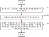
基于所述多个第一反射靶标,测量所述诊断设备在测量坐标系中的第一位置信息;based on the plurality of first reflection targets, measuring first position information of the diagnostic device in the measurement coordinate system;
测量所述第二反射靶标在所述测量坐标系中的第二位置信息;measuring the second position information of the second reflection target in the measurement coordinate system;
根据所述第一位置信息和所述第二位置信息,计算得到所述第二反射靶标在诊断设备的诊断坐标系中的最终位置信息,以根据所述最终位置信息,确定处于在线状态时的诊断设备的位置,进行诊断设备位置匹配。According to the first position information and the second position information, the final position information of the second reflection target in the diagnostic coordinate system of the diagnostic equipment is calculated, so as to determine the online state according to the final position information. The location of the diagnostic device is matched to the location of the diagnostic device.
在可选的实施方式中,所述根据所述第一位置信息和所述第二位置信息,计算得到所述第二反射靶标在诊断设备的诊断坐标系中的最终位置信息的步骤包括:In an optional implementation manner, the step of calculating and obtaining the final position information of the second reflection target in the diagnostic coordinate system of the diagnostic equipment according to the first position information and the second position information includes:
根据以下公式计算得到所述最终位置信息:The final position information is calculated according to the following formula:
DRPT=LTDR)-1·LPTDR PT =L TDR )-1 ·L PT
其中,LTDR为所述第一位置信息,LPT为所述第二位置信息,DRPT为所述最终位置信息。Wherein,L TDR is the first location information,L PT is the second location information, andDR PT is the final location information.
在可选的实施方式中,所述诊断设备标定系统还包括弧摆仪及安装于所述弧摆仪的支撑转动结构,所述第二反射靶标设置于所述支撑转动结构上;In an optional embodiment, the diagnostic equipment calibration system further comprises an arc pendulum and a support rotating structure mounted on the arc pendulum, and the second reflection target is disposed on the support rotating structure;
所述测量所述第二反射靶标在所述测量坐标系中的第二位置信息的步骤包括:The step of measuring the second position information of the second reflection target in the measuring coordinate system includes:
获取所述第二反射靶标跟随所述支撑转动结构在多个预设位置进行旋转运动,得到的多个旋转轨迹信息,其中,每个预设位置是通过所述弧摆仪带动所述支撑转动结构进行弧摆运动达到的;Acquiring a plurality of rotation trajectory information obtained by the second reflection target following the supporting and rotating structure to rotate at a plurality of preset positions, wherein each preset position is driven by the arc pendulum to drive the support to rotate The structure is achieved by the arc pendulum motion;
根据所有旋转轨迹信息,计算得到所述第二反射靶标在多个预设位置进行旋转运动的旋转中心点信息;According to all the rotation trajectory information, calculate and obtain the rotation center point information of the second reflective target rotating at a plurality of preset positions;
根据所述旋转中心点信息,计算得到所述第二反射靶标在多个预设位置进行旋转运动时所在的多条轴线;According to the rotation center point information, calculate and obtain a plurality of axes on which the second reflection target rotates at a plurality of preset positions;
预设位置根据所述多条轴线确定所述第二反射靶标在所述测量坐标系中的第二位置信息。The preset position determines second position information of the second reflection target in the measurement coordinate system according to the multiple axes.
在可选的实施方式中,所述根据所述多条轴线确定所述第二反射靶标在所述测量坐标系中的第二位置信息的步骤包括:In an optional embodiment, the step of determining the second position information of the second reflection target in the measurement coordinate system according to the multiple axes includes:
对预设离散区域内的运动轨迹信息进行离散化处理,得到多个离散点;Perform discretization processing on the motion trajectory information in the preset discrete area to obtain a plurality of discrete points;
计算各离散点与每个轴线之间的距离;Calculate the distance between each discrete point and each axis;
基于该距离,计算各离散点距离所有轴线之和,将距离所有轴线之和最小的离散点的位置信息,作为所述第二反射靶标在所述测量坐标系中的第二位置信息。Based on the distance, the sum of the distances from each discrete point to all axes is calculated, and the position information of the discrete point with the smallest distance from the sum of all axes is used as the second position information of the second reflection target in the measurement coordinate system.
在可选的实施方式中,所述根据所述多条轴线确定所述第二反射靶标在所述测量坐标系中的第二位置信息的步骤包括:In an optional embodiment, the step of determining the second position information of the second reflection target in the measurement coordinate system according to the multiple axes includes:
计算所述多条轴线的交点;calculating an intersection of the plurality of axes;
将该交点的位置信息,作为所述第二反射靶标在所述测量坐标系中的第二位置信息。The position information of the intersection is used as the second position information of the second reflection target in the measurement coordinate system.
第二方面,本申请实施例提供一种诊断设备位置匹配装置,所述装置应用于诊断设备标定系统中的激光跟踪仪,所述诊断设备标定系统还包括诊断设备、第二反射靶标和多个第一反射靶标,所述多个第一反射靶标设置于所述诊断设备,所述第二反射靶标设置于所述诊断设备以外的预设位置,所述装置包括:In a second aspect, an embodiment of the present application provides a device for matching the position of a diagnostic device, the device is applied to a laser tracker in a diagnostic device calibration system, and the diagnostic device calibration system further includes a diagnostic device, a second reflection target, and a plurality of A first reflection target, the plurality of first reflection targets are arranged on the diagnostic equipment, the second reflection targets are arranged at a preset position outside the diagnosis equipment, and the device includes:
第一测量模块,用于基于所述多个第一反射靶标,测量诊断设备在测量坐标系中的第一位置信息;a first measurement module, configured to measure the first position information of the diagnostic device in the measurement coordinate system based on the plurality of first reflection targets;
第二测量模块,用于测量所述第二反射靶标在所述测量坐标系中的第二位置信息;a second measurement module, configured to measure the second position information of the second reflection target in the measurement coordinate system;
计算模块,用于根据所述第一位置信息和所述第二位置信息,计算得到所述第二反射靶标在诊断设备的诊断坐标系中的最终位置信息,以根据所述最终位置信息,确定处于在线状态时的诊断设备的位置,进行诊断设备位置匹配。The calculation module is used to calculate and obtain the final position information of the second reflection target in the diagnostic coordinate system of the diagnostic equipment according to the first position information and the second position information, so as to determine the final position information according to the final position information. The location of the diagnostic device when it is in the online state, and the location of the diagnostic device is matched.
第三方面,本申请实施例提供一种激光跟踪仪,所述激光跟踪仪包括处理器、存储器及总线,所述存储器存储有所述处理器可执行的机器可读指令,当激光跟踪仪运行时,所述处理器及所述存储器之间通过总线通信,所述处理器执行所述机器可读指令,以执行前述实施方式中任意一项所述的诊断设备位置匹配方法的步骤。In a third aspect, an embodiment of the present application provides a laser tracker, where the laser tracker includes a processor, a memory, and a bus, and the memory stores machine-readable instructions executable by the processor. When the laser tracker runs When the processor and the memory communicate via a bus, the processor executes the machine-readable instructions to execute the steps of the method for matching the position of a diagnostic device according to any one of the foregoing embodiments.
第四方面,本申请实施例提供一种诊断设备标定系统,所述诊断设备标定系统包括激光跟踪仪、诊断设备、第二反射靶标和多个第一反射靶标,所述多个第一反射靶标设置于所述诊断设备,所述第二反射靶标设置于所述诊断设备以外的预设位置;In a fourth aspect, an embodiment of the present application provides a diagnostic device calibration system, the diagnostic device calibration system includes a laser tracker, a diagnostic device, a second reflection target, and a plurality of first reflection targets, the plurality of first reflection targets set on the diagnostic equipment, and the second reflection target is set at a preset position outside the diagnostic equipment;
所述激光跟踪仪,用于:The laser tracker is used for:
基于所述多个第一反射靶标,测量诊断设备在测量坐标系中的第一位置信息;Based on the plurality of first reflection targets, measure the first position information of the diagnostic device in the measurement coordinate system;
测量所述第二反射靶标在所述测量坐标系中的第二位置信息;measuring the second position information of the second reflection target in the measurement coordinate system;
根据所述第一位置信息和所述第二位置信息,计算得到所述第二反射靶标在诊断设备的诊断坐标系中的最终位置信息,以根据所述最终位置信息,确定处于在线状态时的诊断设备的位置,进行诊断设备位置匹配。According to the first position information and the second position information, the final position information of the second reflection target in the diagnostic coordinate system of the diagnostic equipment is calculated, so as to determine the online state according to the final position information. The location of the diagnostic device is matched to the location of the diagnostic device.
在可选的实施方式中,所述诊断设备标定系统还包括弧摆仪及安装于所述弧摆仪的支撑转动结构,所述第二反射靶标设置于所述支撑转动结构;In an optional implementation manner, the diagnostic equipment calibration system further includes an arc pendulum and a support rotating structure mounted on the arc pendulum, and the second reflection target is disposed on the support rotating structure;
所述弧摆仪,用于带动所述支撑转动结构进行弧摆运动,以使所述第二反射靶标进行弧摆运动;The arc pendulum instrument is used to drive the supporting and rotating structure to perform arc pendulum motion, so as to make the second reflection target perform arc pendulum motion;
所述激光跟踪仪,还用于:The laser tracker is also used for:
获取所述第二反射靶标跟随所述支撑转动结构在多个预设位置进行旋转运动,得到的多个旋转轨迹信息,其中,每个预设位置是通过所述弧摆仪带动所述支撑转动结构进行弧摆运动达到的;Acquiring a plurality of rotation trajectory information obtained by the second reflection target following the supporting and rotating structure to rotate at a plurality of preset positions, wherein each preset position is driven by the arc pendulum to drive the support to rotate The structure is achieved by the arc pendulum motion;
根据所有旋转轨迹信息,计算得到所述第二反射靶标在多个预设位置进行旋转运动的旋转中心点信息;According to all the rotation trajectory information, calculate and obtain the rotation center point information of the second reflective target rotating at a plurality of preset positions;
根据所述旋转中心点信息,计算得到所述第二反射靶标在多个预设位置进行旋转运动时所在的多条轴线;According to the rotation center point information, calculate and obtain a plurality of axes on which the second reflection target rotates at a plurality of preset positions;
预设位置根据所述多条轴线确定所述第二反射靶标在所述测量坐标系中的第二位置信息。The preset position determines second position information of the second reflection target in the measurement coordinate system according to the multiple axes.
在可选的实施方式中,所述诊断设备标定系统还包括瞄准监视器;In an optional embodiment, the diagnostic equipment calibration system further includes an aiming monitor;
所述瞄准监视器,用于获取第二反射靶标所在的实时位置,比对所述实时位置与所述预设位置,以发送控制信息至弧摆仪;The aiming monitor is used to obtain the real-time position of the second reflection target, compare the real-time position with the preset position, and send control information to the arc pendulum;
所述弧摆仪,用于根据所述控制信息带动所述第二反射靶标运动至所述预设位置。The arc pendulum is used to drive the second reflection target to move to the preset position according to the control information.
本申请实施例提供了一种诊断设备位置匹配方法、装置、激光跟踪仪和诊断设备标定系统,该方法应用于诊断设备标定系统中的激光跟踪仪,诊断设备标定系统还包括诊断设备第二反射靶标和多个第一反射靶标,多个第一反射靶标设置于诊断设备上,第二反射靶标设置于诊断设备以外的预设位置,方法首先基于多个第一反射靶标,测量诊断设备在测量坐标系中的第一位置信息。同时测量第二反射靶标在测量坐标系中的第二位置信息。最后根据第一位置信息和第二位置信息,计算得到第二反射靶标在诊断设备的诊断坐标系中的最终位置信息,以根据所述最终位置信息,确定处于在线状态时的诊断设备的位置,进行诊断设备位置匹配。通过第一位置信息和第二位置信息,简单快速地建立起靶点和诊断设备在同一个坐标系下的相对位置关系,从而简化了位置匹配过程,提高了位置匹配精度。Embodiments of the present application provide a method, device, laser tracker, and diagnostic equipment calibration system for position matching of diagnostic equipment. The method is applied to the laser tracker in the diagnostic equipment calibration system. The diagnostic equipment calibration system further includes a second reflection of the diagnostic equipment. The target and a plurality of first reflection targets, the plurality of first reflection targets are arranged on the diagnostic equipment, and the second reflection targets are arranged at a preset position outside the diagnosis equipment. The method is firstly based on the plurality of first reflection targets. First position information in the coordinate system. At the same time, the second position information of the second reflection target in the measurement coordinate system is measured. Finally, according to the first position information and the second position information, the final position information of the second reflection target in the diagnostic coordinate system of the diagnostic equipment is calculated, so as to determine the position of the diagnostic equipment in an online state according to the final position information, Perform diagnostic device location matching. Through the first position information and the second position information, the relative positional relationship between the target point and the diagnostic equipment in the same coordinate system is simply and quickly established, thereby simplifying the position matching process and improving the position matching accuracy.
附图说明Description of drawings
为了更清楚地说明本申请实施例的技术方案,下面将对实施例中所需要使用的附图作简单地介绍,应当理解,以下附图仅示出了本申请的某些实施例,因此不应被看作是对范围的限定,对于本领域普通技术人员来讲,在不付出创造性劳动的前提下,还可以根据这些附图获得其他相关的附图。In order to illustrate the technical solutions of the embodiments of the present application more clearly, the following drawings will briefly introduce the drawings that need to be used in the embodiments. It should be understood that the following drawings only show some embodiments of the present application, and therefore do not It should be regarded as a limitation of the scope, and for those of ordinary skill in the art, other related drawings can also be obtained according to these drawings without any creative effort.
图1为本申请实施例提供的一种诊断设备标定系统的示意图。FIG. 1 is a schematic diagram of a diagnostic equipment calibration system according to an embodiment of the present application.
图2为本申请实施例提供的一种激光跟踪仪的结构框图。FIG. 2 is a structural block diagram of a laser tracker provided by an embodiment of the present application.
图3为本申请实施例提供的诊断设备位置匹配方法的流程图。FIG. 3 is a flowchart of a method for matching a location of a diagnostic device provided by an embodiment of the present application.
图4为本申请实施例提供的支撑转动结构在多个预设位置的示意图。FIG. 4 is a schematic diagram of the supporting and rotating structure in a plurality of preset positions according to an embodiment of the present application.
图5为本申请实施例提供的诊断设备位置匹配装置的功能模块框图。FIG. 5 is a block diagram of functional modules of the apparatus for matching a position of a diagnostic equipment provided by an embodiment of the present application.
图标:1-诊断设备标定系统;100-激光跟踪仪;110-存储器;120-处理器;130-诊断设备位置匹配装置;131-第一测量模块;132-第二测量模块;133-计算模块;200-诊断设备;300-第二反射靶标;400-第一反射靶标;500-支撑转动结构。Icons: 1-diagnostic equipment calibration system; 100-laser tracker; 110-memory; 120-processor; 130-diagnostic equipment position matching device; 131-first measurement module; 132-second measurement module; 133-calculation module 200-diagnostic equipment; 300-second reflection target; 400-first reflection target; 500-support rotating structure.
具体实施方式Detailed ways
为使本申请实施例的目的、技术方案和优点更加清楚,下面将结合本申请实施例中的附图,对本申请实施例中的技术方案进行清楚、完整地描述,显然,所描述的实施例是本申请一部分实施例,而不是全部的实施例。通常在此处附图中描述和示出的本申请实施例的组件可以以各种不同的配置来布置和设计。In order to make the purposes, technical solutions and advantages of the embodiments of the present application clearer, the technical solutions in the embodiments of the present application will be described clearly and completely below with reference to the drawings in the embodiments of the present application. Obviously, the described embodiments It is a part of the embodiments of the present application, but not all of the embodiments. The components of the embodiments of the present application generally described and illustrated in the drawings herein may be arranged and designed in a variety of different configurations.
因此,以下对在附图中提供的本申请的实施例的详细描述并非旨在限制要求保护的本申请的范围,而是仅仅表示本申请的选定实施例。基于本申请中的实施例,本领域普通技术人员在没有作出创造性劳动前提下所获得的所有其他实施例,都属于本申请保护的范围。Thus, the following detailed description of the embodiments of the application provided in the accompanying drawings is not intended to limit the scope of the application as claimed, but is merely representative of selected embodiments of the application. Based on the embodiments in the present application, all other embodiments obtained by those of ordinary skill in the art without creative work fall within the protection scope of the present application.
应注意到:相似的标号和字母在下面的附图中表示类似项,因此,一旦某一项在一个附图中被定义,则在随后的附图中不需要对其进行进一步定义和解释。It should be noted that like numerals and letters refer to like items in the following figures, so once an item is defined in one figure, it does not require further definition and explanation in subsequent figures.
在本申请的描述中,需要说明的是,若出现术语“上”、“下”、“内”、“外”等指示的方位或位置关系为基于附图所示的方位或位置关系,或者是该发明产品使用时惯常摆放的方位或位置关系,仅是为了便于描述本申请和简化描述,而不是指示或暗示所指的装置或元件必须具有特定的方位、以特定的方位构造和操作,因此不能理解为对本申请的限制。In the description of this application, it should be noted that, if the terms "upper", "lower", "inner", "outer", etc. appear, the orientation or positional relationship indicated is based on the orientation or positional relationship shown in the drawings, or It is the usual orientation or positional relationship when the product of the invention is used, which is only for the convenience of describing the application and simplifying the description, rather than indicating or implying that the device or element referred to must have a specific orientation, be constructed and operated in a specific orientation , so it cannot be construed as a limitation on this application.
此外,若出现术语“第一”、“第二”等仅用于区分描述,而不能理解为指示或暗示相对重要性。In addition, where the terms "first", "second" and the like appear, they are only used to differentiate the description, and should not be construed as indicating or implying relative importance.
需要说明的是,在不冲突的情况下,本申请的实施例中的特征可以相互结合。It should be noted that the features in the embodiments of the present application may be combined with each other under the condition of no conflict.
如背景技术所介绍,惯性约束聚变实验需要各种诊断设备200进行准确地监测。要获取准确的实验数据,大部分诊断设备200要对打靶目标进行精确地瞄准,由于其自身并不具备瞄准功能,需要搭载在通用诊断搭载平台上进行瞄准。As described in the background, inertial confinement fusion experiments require various
美国早期采用对置端口对准系统和腔室内部监视系统,这一方式需要占用较多法兰口,瞄准效率低;我国激光装置上当前诊断设备的瞄准采用双目瞄准,需进行单台套瞄准,耗时较长;法国兆焦耳装置采用双激光束实现诊断设备的瞄准,精度在25-250μm;美国大型激光装置NIF上从2017年开始采用激光跟踪仪进行瞄准,瞄准精度在200μm以内,不需要靶室照明,能够适应各种形状的靶,且能够同时实现多台诊断设备的瞄准。In the early days of the United States, the opposite port alignment system and the internal monitoring system of the chamber were adopted. This method requires a lot of flange ports and has low aiming efficiency; the current diagnostic equipment on the laser device in our country adopts binocular aiming, which requires a single set of Aiming takes a long time; the French megajoule device uses dual laser beams to achieve the aiming of the diagnostic equipment, with an accuracy of 25-250 μm; the large-scale laser device NIF in the United States has used a laser tracker for aiming since 2017, and the aiming accuracy is within 200 μm, It does not need target room lighting, can adapt to targets of various shapes, and can simultaneously achieve the targeting of multiple diagnostic equipment.
通常采用激光跟踪仪完成瞄准主要步骤有:靶场基准的建立,诊断设备离线标定,靶传感器在线标定,诊断设备在线瞄准。其中,诊断设备离线标定过程需在离线情况确定出靶点与诊断设备的相对位置关系,而瞄准监视系统只能测得靶点位置而无法测得诊断设备的位置,激光跟踪仪可根据靶标测得诊断设备的位置而无法测得靶点的位置,使得在同一个坐标系下建立起靶点和诊断设备的关系存在困难,目前采用球面拟合确定靶点坐标的方法实现难度大,过程复杂。Usually, the main steps of using laser tracker to complete aiming are: establishment of shooting range benchmark, offline calibration of diagnostic equipment, online calibration of target sensor, and online targeting of diagnostic equipment. Among them, the offline calibration process of the diagnostic equipment needs to determine the relative positional relationship between the target point and the diagnostic equipment in the offline situation, while the aiming monitoring system can only measure the position of the target point but cannot measure the position of the diagnostic equipment. It is difficult to establish the relationship between the target point and the diagnostic equipment in the same coordinate system because the position of the diagnostic equipment cannot be measured but the position of the target point cannot be measured. .
因此,如何简单快速地得到靶点和诊断设备在同一坐标系下的关系,进而得到靶点在诊断设坐标系下的坐标,是值得研究的技术问题。Therefore, how to simply and quickly obtain the relationship between the target point and the diagnostic equipment in the same coordinate system, and then obtain the coordinates of the target point in the diagnostic coordinate system, is a technical problem worth studying.
基于上述发现,本申请实施例提供了一种诊断设备位置匹配方法、装置、激光跟踪仪和诊断设备标定系统。该诊断设备位置匹配方法通过在诊断设备上设置第一反射靶标,在预设位置设置第二反射靶标,进而确定出诊断设备的位置信息及靶点的位置信息,利用上述诊断设备的位置信息及靶点的位置信息建立起靶点和诊断设备在同一个坐标系下的关系,进而得到靶点在诊断设备坐标系下的坐标。下面对上述方案进行详细阐述。Based on the above findings, the embodiments of the present application provide a method, device, laser tracker, and diagnostic equipment calibration system for position matching of diagnostic equipment. The method for matching the position of the diagnostic equipment includes setting the first reflective target on the diagnostic equipment and setting the second reflective target at the preset position, thereby determining the position information of the diagnostic equipment and the position information of the target point, and using the position information of the diagnostic equipment and the position information of the target point. The position information of the target point establishes the relationship between the target point and the diagnostic equipment in the same coordinate system, and then obtains the coordinates of the target point in the coordinate system of the diagnostic equipment. The above scheme will be described in detail below.
请参阅图1,图1为本申请实施例提供的一种诊断设备标定系统1的结构框图。诊断设备标定系统1包括激光跟踪仪100、诊断设备200、第二反射靶标300和多个第一反射靶标400,多个第一反射靶标400设置于诊断设备200,第二反射靶标300设置于诊断设备200以外的预设位置。Please refer to FIG. 1. FIG. 1 is a structural block diagram of a diagnostic
激光跟踪仪100,用于基于多个第一反射靶标400,测量诊断设备200在测量坐标系中的第一位置信息。同时测量第二反射靶标300在测量坐标系中的第二位置信息。最后根据第一位置信息和第二位置信息,计算得到第二反射靶标300在诊断设备200的诊断坐标系中的最终位置信息。The
其中,第一反射靶标400或第二反射靶标300均可以是反射球跟踪球靶或反射镜。同时上述预设位置可基于测量物及测量原理的不同,根据经验值或理论值确定。第一反射靶标400至少为6个,安装在诊断设备200的不同方位。Wherein, both the
如此,将诊断设备200与第二反射靶标300在测量坐标系中的位置信息转换为在诊断设备200的诊断坐标系的位置信息,从而使得诊断设备200处于在线状态时,能根据第二反射靶标300在诊断坐标系中的位置信息进行位置匹配,简化了位置匹配过程,提高了位置匹配精度。In this way, the position information of the
进一步地,诊断设备标定系统1还包括弧摆仪及安装于弧摆仪的支撑转动结构500,第二反射靶标300设置于支撑转动结构500。Further, the diagnostic
弧摆仪,用于带动支撑转动结构500进行弧摆运动,以使第二反射靶标300进行弧摆运动。The arc pendulum is used to drive the supporting and
可以理解的是,弧摆仪可以是二维弧摆台或者可以实现弧摆运动的仪器。例如,该弧摆仪包括多个圆形轨道,每个圆形轨道的圆心均位于靶点位置,支撑转动结构500设置于圆形轨道上,支撑转动结构500沿圆形轨道进行弧摆运动。It can be understood that the arc pendulum instrument can be a two-dimensional arc pendulum table or an instrument that can realize arc pendulum motion. For example, the arc pendulum includes a plurality of circular orbits, the center of each circular orbit is located at the target position, the supporting and
激光跟踪仪100,还用于获取所述第二反射靶标300跟随所述支撑转动结构500在多个预设位置进行旋转运动,得到的多个旋转轨迹信息,其中,每个预设位置是通过弧摆仪带动所述支撑转动结构500进行弧摆运动达到的;根据所有旋转轨迹信息,计算得到所述第二反射靶标300在多个预设位置进行旋转运动的旋转中心点信息;根据所述旋转中心点信息,计算得到所述第二反射靶标300在多个预设位置进行旋转运动时所在的多条轴线。最后,根据多条轴线确定第二反射靶标300在测量坐标系中的第二位置信息。The
其中,一方面,由于第二反射靶标300体积较小,为了使得激光跟踪仪得到的测量数据更加准确,第二反射靶标300可以为多个。另一方面,若第二反射靶标300的数量为1个,则1个第二反射靶标300跟随支撑转动结构500旋转后,测量计算得到的是一个旋转中心点,然而,一个点无法确定一条线。因此,作为一种优选的实施方式,第二反射靶标300的数量可以为两个。Wherein, on the one hand, since the volume of the second
两个第二反射靶标300跟随支撑转动结构500旋转后,则可以测量计算得到两个旋转中心点,如此,则可根据两个旋转中心点确定一条轴线。After the two second
进一步地,本申请实施例还通过在多个预设位置对第二反射靶标300进行旋转运动,从而得到第二反射靶标300在多个预设位置处的轴线,从而提高激光跟踪仪100测量的准确度,进而提高位置匹配时的对准精度。Further, in the embodiment of the present application, the second
进一步地,诊断设备标定系统1还包括瞄准监视器。Further, the diagnostic
瞄准监视器,用于获取第二反射靶标300所在的实时位置,比对实时位置与预设位置,以发送控制信息至弧摆仪。The aiming monitor is used to obtain the real-time position of the second
弧摆仪,用于根据控制信息带动第二反射靶标300运动至预设位置。The arc pendulum is used to drive the
通过瞄准监视器监控第二反射靶标300的实时位置,并将实时位置与预设位置进行比较,以通过弧摆仪将第二反射靶标300准确地放置于预设位置。The real-time position of the
请结合参阅图2,图2为本申请实施例提供的一种激光跟踪仪100的结构框图。设备可以包括处理器120、存储器110、诊断设备位置匹配装置130及总线,存储器110存储有处理器120可执行的机器可读指令,当激光跟踪仪100运行时,处理器120及存储器110之间通过总线通信,处理器120执行机器可读指令,并执行诊断设备位置匹配方法的步骤。Please refer to FIG. 2 , which is a structural block diagram of a
存储器110、处理器120以及其他各元件相互之间直接或间接地电性连接,以实现信号的传输或交互。The memory 110 , the processor 120 and other components are directly or indirectly electrically connected to each other to realize signal transmission or interaction.
例如,这些元件相互之间可通过一条或多条通讯总线或信号线实现电性连接。诊断设备位置匹配装置130包括至少一个可以软件或固件(firmware)的形式存储于存储器110中的软件功能模块。处理器120用于执行存储器110中存储的可执行模块,例如诊断设备位置匹配装置130所包括的软件功能模块或计算机程序。For example, these elements may be electrically connected to each other through one or more communication buses or signal lines. The diagnostic equipment
其中,存储器110可以是,但不限于,随机读取存储器(Random ACCess memory,RAM),只读存储器(Read Only Memory,ROM),可编程只读存储器(Programmable Read-OnlyMemory,PROM),可擦除只读存储器(Erasable Programmable Read-Only Memory,EPROM),电可擦除只读存储器(Electric Erasable Programmable Read-Only Memory,EEPROM)等。The memory 110 may be, but not limited to, a random access memory (Random ACCess memory, RAM), a read only memory (Read Only Memory, ROM), a programmable read only memory (Programmable Read-Only Memory, PROM), an erasable memory In addition to read-only memory (Erasable Programmable Read-Only Memory, EPROM), Electrical Erasable Programmable Read-Only Memory (Electric Erasable Programmable Read-Only Memory, EEPROM) and the like.
处理器120可以是一种集成电路芯片,具有信号处理能力。上述处理器120可以是通用处理器,包括中央处理器(Central Processing Unit,简称CPU)、网络处理器(NetworkProcessor,简称NP)等。The processor 120 may be an integrated circuit chip with signal processing capability. The foregoing processor 120 may be a general-purpose processor, including a central processing unit (Central Processing Unit, CPU for short), a network processor (Network Processor, NP for short), and the like.
还可以是数字信号处理器(DSP)、专用集成电路(ASIC)、现场可编程门阵列(FPGA)或者其他可编程逻辑器件、分立门或者晶体管逻辑器件、分立硬件组件。可以实现或者执行本申请实施例中的公开的各方法、步骤及逻辑框图。通用处理器可以是微处理器或者该处理器也可以是任何常规的处理器等。It may also be a digital signal processor (DSP), application specific integrated circuit (ASIC), field programmable gate array (FPGA) or other programmable logic device, discrete gate or transistor logic device, discrete hardware components. The methods, steps, and logic block diagrams disclosed in the embodiments of this application can be implemented or executed. A general purpose processor may be a microprocessor or the processor may be any conventional processor or the like.
本申请实施例中,存储器110用于存储程序,处理器120用于在接收到执行指令后,执行程序。本申请实施例任一实施方式所揭示的流程定义的方法可以应用于处理器120中,或者由处理器120实现。In this embodiment of the present application, the memory 110 is used to store the program, and the processor 120 is used to execute the program after receiving the execution instruction. The method for process definition disclosed in any implementation manner of this embodiment of the present application may be applied to the processor 120 or implemented by the processor 120 .
进一步地,激光跟踪仪100还可以包括应用计算机,该应用计算机用于发出测量指令和接收测量数据。激光跟踪仪100还可以包括气象站,该气象站用于记录空气压力和温度,并通过串行接口传送给应用计算机。激光跟踪仪100还可以包括三角支架、推车等,该三角支架及推车用于固定激光跟踪仪的本体,调整高度,保证测量时的稳定性。Further, the
可以理解,图2所示的结构仅为示意。激光跟踪仪100还可以具有比图2所示更多或者更少的组件,或者具有与图2所示不同的配置。图2所示的各组件可以采用硬件、软件或其组合实现。It can be understood that the structure shown in FIG. 2 is for illustration only. The
作为一种可能的实施方式,本申请实施例提供了一种诊断设备位置匹配方法,请结合参阅3,图3为本申请实施例提供的诊断设备位置匹配方法的流程图。该诊断设备位置匹配方法应用于上述诊断设备标定系统1中的激光跟踪仪100。下面结合图3所示的具体流程进行详细描述。As a possible implementation manner, an embodiment of the present application provides a method for matching the position of a diagnostic device. Please refer to 3 in conjunction. FIG. 3 is a flowchart of the method for matching the position of a diagnostic device provided by the embodiment of the present application. The method for matching the position of the diagnostic equipment is applied to the
步骤S1,基于多个第一反射靶标400,测量诊断设备200在测量坐标系中的第一位置信息。Step S1, based on the plurality of first reflection targets 400, measure the first position information of the
步骤S2,测量第二反射靶标300在测量坐标系中的第二位置信息。Step S2, measuring the second position information of the second
步骤S3,根据第一位置信息和第二位置信息,计算得到第二反射靶标300在诊断设备200的诊断坐标系中的最终位置信息,以根据所述最终位置信息,确定处于在线状态时的诊断设备200的位置,进行诊断设备位置匹配。Step S3, according to the first position information and the second position information, calculate and obtain the final position information of the
如此,将可简单快速地将诊断设备200与第二反射靶标300在测量坐标系中的位置信息转换为在诊断设备200的诊断坐标系的位置信息,从而使得诊断设备200处于在线状态时,能根据第二反射靶标300在诊断坐标系中的位置信息进行位置匹配,简化了位置匹配过程,提高了位置匹配精度。In this way, the position information of the
应当理解,在其它实施例中,本实施例的诊断设备位置匹配方法中的部分步骤的顺序可以根据实际需要相互交换,或者其中的部分步骤也可以省略或删除。It should be understood that, in other embodiments, the order of some steps in the method for matching the position of a diagnostic device in this embodiment may be exchanged according to actual needs, or some steps may be omitted or deleted.
进一步地,作为一种可能的实施方式,可根据以下方式由第一位置信息和第二位置信息,计算得到第二反射靶标300在诊断设备200的诊断坐标系中的最终位置信息:Further, as a possible implementation manner, the final position information of the
根据以下公式计算得到最终位置信息:The final position information is calculated according to the following formula:
DRPT=(LTDR)-1·LPTDR PT =(L TDR )-1 ·L PT
其中,LTDR为第一位置信息,LPT为第二位置信息,DRPT为最终位置信息。DR为诊断设备200,T为第二反射靶标300。Wherein,L TDR is the first position information,L PT is the second position information, andDR PT is the final position information. DR is the
获得第二反射靶标300在测量坐标系中的第二位置信息,获得诊断设备200在测量坐标系中的第一位置信息,将第一位置信息和第二位置信息带入上述公式,即可求得第二反射靶标300在诊断坐标系中的最终位置信息。Obtain the second position information of the second
进一步地,请结合参阅图4,作为一种可能的实施方式,可通过以下方式测量第二反射靶标300在测量坐标系中的第二位置信息:Further, referring to FIG. 4 , as a possible implementation manner, the second position information of the second
首先,获取所述第二反射靶标300跟随所述支撑转动结构500在多个预设位置进行旋转运动,得到的多个旋转轨迹信息,其中,每个预设位置是通过弧摆仪带动所述支撑转动结构500进行弧摆运动达到的。First, obtain a plurality of rotational trajectory information obtained by the
接着,根据所有旋转轨迹信息,计算得到所述第二反射靶标300在多个预设位置进行旋转运动的旋转中心点信息。Next, according to all the rotation trajectory information, the rotation center point information of the second
然后,根据所有旋转轨迹信息,计算得到所述第二反射靶标300在多个预设位置进行旋转运动的旋转中心点信息。Then, according to all the rotation trajectory information, the rotation center point information of the second
然后,根据所述旋转中心点信息,计算得到所述第二反射靶标300在多个预设位置进行旋转运动时所在的多条轴线。Then, according to the rotation center point information, a plurality of axes on which the second
最后,根据多条轴线确定第二反射靶标300在测量坐标系中的第二位置信息。Finally, the second position information of the
其中,预设位置可以是沿第一方向转动0-360度,预设位置也可以是沿第二方向转动0-360度。需要注意的是,每一次弧摆运动时,预设位置均不相同。The preset position may be a rotation of 0-360 degrees along the first direction, and the preset position may also be a rotation of 0-360 degrees along the second direction. It should be noted that each time the arc pendulum moves, the preset position is different.
例如,作为一种可能的实施场景,假设第二反射靶标300跟随支撑转动结构500进行了三次弧摆运动,则第一次弧摆运动时,预设位置可以是沿第一方向转动90度;第二次弧摆运动时,预设位置可以是沿第二方向转动90度;第三次弧摆运动时,预设位置可以是沿第一方向转动180度。For example, as a possible implementation scenario, assuming that the second
根据不同的第二反射靶标300在不同预设位置跟随支撑转动结构500进行旋转运动,得到的多个旋转运动轨迹,根据所有旋转轨迹信息,计算得到所述第二反射靶标300在多个预设位置进行旋转运动的旋转中心点信息,根据所述旋转中心点信息,计算得到所述第二反射靶标300在多个预设位置进行旋转运动时所在的多条轴线。According to different second
例如,当支撑转动结构500在沿第一方向转动90度时的轴线、当支撑转动结构500在沿第二方向转动90度时的轴线以及当支撑转动结构500在沿第一方向转动180度时的轴线。For example, the axis when the
其中,作为一种可能的实施方式,根据多条轴线确定第二位置信息的方式可以包括:Wherein, as a possible implementation manner, the manner of determining the second position information according to the multiple axes may include:
首先,对预设离散区域内的运动轨迹信息进行离散化处理,得到多个离散点。First, the motion trajectory information in the preset discrete area is discretized to obtain a plurality of discrete points.
接着,计算各离散点与每个轴线之间的距离。Next, calculate the distance between each discrete point and each axis.
然后,基于该距离,计算各离散点距离所有轴线之和。Then, based on this distance, the sum of the distances of each discrete point from all axes is calculated.
最后,将距离所有轴线之和最小的离散点的位置信息,作为第二反射靶标300在测量坐标系中的第二位置信息。Finally, the position information of the discrete points with the smallest distance from the sum of all axes is used as the second position information of the
需要理解的是,该预设离散区域应包括第二反射靶标所在的空间区域,同时,该预设离散区域越小,计算的复杂度越低,计算速率越快,其具体范围可根据实际需求进行设定。It should be understood that the preset discrete area should include the spatial area where the second reflective target is located. At the same time, the smaller the preset discrete area is, the lower the computational complexity and the faster the calculation rate. The specific range can be based on actual needs. Make settings.
作为另一种可能的实施方式,根据多条轴线确定第二位置信息的方式还可以包括:As another possible implementation manner, the manner of determining the second position information according to the multiple axes may further include:
首先,计算多条轴线的交点。First, calculate the intersection of multiple axes.
接着,将该交点的位置信息,作为第二反射靶标300在测量坐标系中的第二位置信息。Next, the position information of the intersection is used as the second position information of the
例如,假设拟合得到的轴线1在测量坐标系中的方程为

可以理解的是,轴线还可以是3条、4条、5条等。当轴线为多条时,同样使用上述方式求解超定方程组,求其最小二乘解即可得到多条轴线的交点在测量坐标系中的位置信息。It can be understood that the number of axes can also be 3, 4, 5, etc. When there are multiple axes, the above method is also used to solve the overdetermined equation system, and the position information of the intersection of the multiple axes in the measurement coordinate system can be obtained by finding its least squares solution.
基于同一发明构思,请结合参阅图5,图5为本申请实施例提供的诊断设备位置匹配装置130的功能模块框图。本申请实施例中还提供了与上述诊断设备位置匹配方法对应的诊断设备位置匹配装置130,装置应用于诊断设备标定系统1中的激光跟踪仪100,诊断设备标定系统1还包括诊断设备200、第二反射靶标300和多个第一反射靶标400,多个第一反射靶标400设置于诊断设备200,第二反射靶标300设置于诊断设备200以外的预设位置,装置包括:Based on the same inventive concept, please refer to FIG. 5 , which is a block diagram of functional modules of the
第一测量模块131,用于基于多个第一反射靶标400,测量诊断设备200在测量坐标系中的第一位置信息。The
第二测量模块132,用于测量第二反射靶标300在测量坐标系中的第二位置信息。The
计算模块133,用于根据第一位置信息和第二位置信息,计算得到第二反射靶标300在诊断设备200的诊断坐标系中的最终位置信息,以根据所述最终位置信息,确定处于在线状态时的诊断设备200的位置,进行诊断设备位置匹配。The
由于本申请实施例中的装置解决问题的原理与本申请实施例上述诊断设备位置匹配方法相似,因此装置的实施原理可以参见方法的实施原理,重复之处不再赘述。Since the principle of the device in the embodiment of the present application for solving the problem is similar to the above-mentioned method for matching the position of the diagnostic equipment in the embodiment of the present application, the implementation principle of the device can be referred to the implementation principle of the method, and the repetition will not be repeated.
本申请实施例也提供了一种可读存储介质,可读存储介质中存储有计算机程序,计算机程序被执行时实现上述的诊断设备位置匹配方法。Embodiments of the present application also provide a readable storage medium, where a computer program is stored in the readable storage medium, and when the computer program is executed, the foregoing method for matching the position of a diagnostic device is implemented.
综上所述,本申请实施例提供了一种诊断设备位置匹配方法、装置、激光跟踪仪和诊断设备标定系统,该方法应用于诊断设备标定系统中的激光跟踪仪,诊断设备标定系统还包括诊断设备第二反射靶标和多个第一反射靶标,多个第一反射靶标设置于诊断设备上,第二反射靶标设置于诊断设备以外的预设位置,方法首先基于多个第一反射靶标,测量诊断设备在测量坐标系中的第一位置信息。同时测量第二反射靶标在测量坐标系中的第二位置信息。最后根据第一位置信息和第二位置信息,计算得到第二反射靶标在诊断设备的诊断坐标系中的最终位置信息,以根据所述最终位置信息,确定处于在线状态时的诊断设备的位置,进行诊断设备位置匹配。通过第一位置信息和第二位置信息,简单快速地建立起靶点和诊断设备在同一个坐标系下的相对位置关系,从而简化了位置匹配过程,提高了位置匹配精度。To sum up, the embodiments of the present application provide a method, device, laser tracker, and diagnostic equipment calibration system for position matching of diagnostic equipment. The method is applied to the laser tracker in the diagnostic equipment calibration system. The diagnostic equipment calibration system further includes: The diagnostic equipment includes a second reflection target and a plurality of first reflection targets, the plurality of first reflection targets are arranged on the diagnosis equipment, and the second reflection targets are arranged at a preset position outside the diagnosis equipment. The method is firstly based on the plurality of first reflection targets, Measure the first position information of the diagnostic device in the measurement coordinate system. At the same time, the second position information of the second reflection target in the measurement coordinate system is measured. Finally, according to the first position information and the second position information, the final position information of the second reflection target in the diagnostic coordinate system of the diagnostic equipment is calculated, so as to determine the position of the diagnostic equipment in an online state according to the final position information, Perform diagnostic device location matching. Through the first position information and the second position information, the relative positional relationship between the target point and the diagnostic equipment in the same coordinate system is simply and quickly established, thereby simplifying the position matching process and improving the position matching accuracy.
在本申请所提供的实施例中,应该理解到,所揭露的装置和方法,也可以通过其它的方式实现。以上所描述的装置实施例仅仅是示意性的,例如,附图中的流程图和框图显示了根据本申请的实施例的装置、方法和计算机程序产品的可能实现的体系架构、功能和操作。在这点上,流程图或框图中的每个方框可以代表一个模块、程序段或代码的一部分,所述模块、程序段或代码的一部分包含一个或多个用于实现规定的逻辑功能的可执行指令。也应当注意,在有些作为替换的实现方式中,方框中所标注的功能也可以以不同于附图中所标注的顺序发生。例如,两个连续的方框实际上可以基本并行地执行,它们有时也可以按相反的顺序执行,这依所涉及的功能而定。也要注意的是,框图和/或流程图中的每个方框、以及框图和/或流程图中的方框的组合,可以用执行规定的功能或动作的专用的基于硬件的系统来实现,或者可以用专用硬件与计算机指令的组合来实现。In the embodiments provided in this application, it should be understood that the disclosed apparatus and method may also be implemented in other manners. The apparatus embodiments described above are merely illustrative, eg, the flowcharts and block diagrams in the accompanying drawings illustrate the architecture, functionality and operation of possible implementations of apparatuses, methods and computer program products according to embodiments of the present application. In this regard, each block in the flowchart or block diagrams may represent a module, segment, or portion of code that contains one or more functions for implementing the specified logical function(s) executable instructions. It should also be noted that, in some alternative implementations, the functions noted in the block may occur out of the order noted in the figures. For example, two blocks in succession may, in fact, be executed substantially concurrently, or the blocks may sometimes be executed in the reverse order, depending upon the functionality involved. It is also noted that each block of the block diagrams and/or flowchart illustrations, and combinations of blocks in the block diagrams and/or flowchart illustrations, can be implemented in dedicated hardware-based systems that perform the specified functions or actions , or can be implemented in a combination of dedicated hardware and computer instructions.
需要说明的是,在本文中,术语“包括”、“包含”或者其任何其他变体意在涵盖非排他性的包含,从而使得包括一系列要素的过程、方法、物品或者设备不仅包括那些要素,而且还包括没有明确列出的其他要素,或者是还包括为这种过程、方法、物品或者设备所固有的要素。在没有更多限制的情况下,由语句“包括一个……”限定的要素,并不排除在包括所述要素的过程、方法、物品或者设备中还存在另外的相同要素。It should be noted that, herein, the terms "comprising", "comprising" or any other variation thereof are intended to encompass non-exclusive inclusion, such that a process, method, article or device comprising a series of elements includes not only those elements, It also includes other elements not expressly listed or inherent to such a process, method, article or apparatus. Without further limitation, an element qualified by the phrase "comprising a..." does not preclude the presence of additional identical elements in a process, method, article or apparatus that includes the element.
以上所述,仅为本申请的具体实施方式,但本申请的保护范围并不局限于此,任何熟悉本技术领域的技术人员在本申请揭露的技术范围内,可轻易想到的变化或替换,都应涵盖在本申请的保护范围之内。因此,本申请的保护范围应以所述权利要求的保护范围为准。The above are only specific embodiments of the present application, but the protection scope of the present application is not limited to this. Any person skilled in the art can easily think of changes or substitutions within the technical scope disclosed in the present application, All should be covered within the scope of protection of this application. Therefore, the protection scope of the present application should be subject to the protection scope of the claims.
Claims (10)
Priority Applications (1)
| Application Number | Priority Date | Filing Date | Title |
|---|---|---|---|
| CN202010486925.7ACN111649668B (en) | 2020-06-01 | 2020-06-01 | Diagnostic equipment position matching method, device, laser tracker and diagnostic equipment calibration system |
Applications Claiming Priority (1)
| Application Number | Priority Date | Filing Date | Title |
|---|---|---|---|
| CN202010486925.7ACN111649668B (en) | 2020-06-01 | 2020-06-01 | Diagnostic equipment position matching method, device, laser tracker and diagnostic equipment calibration system |
Publications (2)
| Publication Number | Publication Date |
|---|---|
| CN111649668Atrue CN111649668A (en) | 2020-09-11 |
| CN111649668B CN111649668B (en) | 2022-02-15 |
Family
ID=72347095
Family Applications (1)
| Application Number | Title | Priority Date | Filing Date |
|---|---|---|---|
| CN202010486925.7AActiveCN111649668B (en) | 2020-06-01 | 2020-06-01 | Diagnostic equipment position matching method, device, laser tracker and diagnostic equipment calibration system |
Country Status (1)
| Country | Link |
|---|---|
| CN (1) | CN111649668B (en) |
Cited By (1)
| Publication number | Priority date | Publication date | Assignee | Title |
|---|---|---|---|---|
| CN117854751A (en)* | 2024-01-09 | 2024-04-09 | 北京星环聚能科技有限公司 | State detection method and system of nuclear fusion reaction device and nuclear fusion reaction system |
Citations (6)
| Publication number | Priority date | Publication date | Assignee | Title |
|---|---|---|---|---|
| US20050119569A1 (en)* | 2003-10-22 | 2005-06-02 | Aloka Co., Ltd. | Ultrasound diagnosis apparatus |
| CN106595654A (en)* | 2016-12-13 | 2017-04-26 | 天津大学 | Continuous tracking measurement method and device for laser tracking measurement system |
| CN108871195A (en)* | 2018-07-25 | 2018-11-23 | 中国工程物理研究院激光聚变研究中心 | Physical diagnosis equipment method of sight based on reflection sphere tracking ball target |
| CN108921901A (en)* | 2018-05-04 | 2018-11-30 | 北京航空航天大学 | A kind of big visual field camera calibration method based on accurate two-axis platcform and laser tracker |
| CN109269408A (en)* | 2018-10-10 | 2019-01-25 | 中国航空工业集团公司洛阳电光设备研究所 | A kind of target plate device and target plate localization method based on laser tracking technology |
| CN109903333A (en)* | 2019-02-02 | 2019-06-18 | 宁波吉利汽车研究开发有限公司 | Coordinate system correction method, device and electronic equipment of robot workpiece |
- 2020
- 2020-06-01CNCN202010486925.7Apatent/CN111649668B/enactiveActive
Patent Citations (6)
| Publication number | Priority date | Publication date | Assignee | Title |
|---|---|---|---|---|
| US20050119569A1 (en)* | 2003-10-22 | 2005-06-02 | Aloka Co., Ltd. | Ultrasound diagnosis apparatus |
| CN106595654A (en)* | 2016-12-13 | 2017-04-26 | 天津大学 | Continuous tracking measurement method and device for laser tracking measurement system |
| CN108921901A (en)* | 2018-05-04 | 2018-11-30 | 北京航空航天大学 | A kind of big visual field camera calibration method based on accurate two-axis platcform and laser tracker |
| CN108871195A (en)* | 2018-07-25 | 2018-11-23 | 中国工程物理研究院激光聚变研究中心 | Physical diagnosis equipment method of sight based on reflection sphere tracking ball target |
| CN109269408A (en)* | 2018-10-10 | 2019-01-25 | 中国航空工业集团公司洛阳电光设备研究所 | A kind of target plate device and target plate localization method based on laser tracking technology |
| CN109903333A (en)* | 2019-02-02 | 2019-06-18 | 宁波吉利汽车研究开发有限公司 | Coordinate system correction method, device and electronic equipment of robot workpiece |
Cited By (1)
| Publication number | Priority date | Publication date | Assignee | Title |
|---|---|---|---|---|
| CN117854751A (en)* | 2024-01-09 | 2024-04-09 | 北京星环聚能科技有限公司 | State detection method and system of nuclear fusion reaction device and nuclear fusion reaction system |
Also Published As
| Publication number | Publication date |
|---|---|
| CN111649668B (en) | 2022-02-15 |
Similar Documents
| Publication | Publication Date | Title |
|---|---|---|
| US8773667B2 (en) | Sphere bar probe | |
| US7742176B2 (en) | Method and system for determining the spatial position of a hand-held measuring appliance | |
| EP3693759B1 (en) | System and method for tracking motion of target in indoor environment | |
| CN111123280B (en) | Laser radar positioning method, device, system, electronic equipment and storage medium | |
| US20140185059A1 (en) | Automatic measurement of dimensional data with a laser tracker | |
| US20040160594A1 (en) | Measurement of spatial coordinates | |
| CN106802412B (en) | Short-distance mobile positioning system and method based on laser and wireless technology | |
| CN103969625A (en) | Wireless positioning method | |
| CN108513353B (en) | Method for realizing mobile robot positioning based on double beacon nodes | |
| CN111649668B (en) | Diagnostic equipment position matching method, device, laser tracker and diagnostic equipment calibration system | |
| JP7341632B2 (en) | reflective target | |
| WO2020113391A1 (en) | Heading determining method and device, storage medium, and moving platform | |
| EP3934777B1 (en) | Thermopile array fusion tracking | |
| CN103033182B (en) | Determine the detent mechanism of the 3rd target | |
| CN114690179A (en) | Indoor tracking and positioning method and device based on short-distance radar and strapdown inertial navigation | |
| GB2510510A (en) | Automatic measurement of dimensional data with a laser tracker | |
| EP3540463B1 (en) | Radar and ultrasound sensor based real time tracking of a moving object | |
| Depenthal | Path tracking with IGPS | |
| US11709269B2 (en) | Method, processing unit and surveying instrument for improved tracking of a target | |
| RU2667115C1 (en) | Method of positioning object with azimuth cutting from first measuring point and angle of site with the range - from second | |
| US20220182853A1 (en) | Automatic handling of network communication failure in two-dimensional and three-dimensional coordinate measurement devices | |
| CN110988895A (en) | Measuring device, system and method | |
| CN211786100U (en) | Measuring device and system | |
| CN106908029A (en) | Point target space ranging positioner and method | |
| US20250163674A1 (en) | Six-way blade orientation determination from lifting movement |
Legal Events
| Date | Code | Title | Description |
|---|---|---|---|
| PB01 | Publication | ||
| PB01 | Publication | ||
| SE01 | Entry into force of request for substantive examination | ||
| SE01 | Entry into force of request for substantive examination | ||
| GR01 | Patent grant | ||
| GR01 | Patent grant |