CN111643223B - Grafts to repair or replace the heart's own valves - Google Patents
Grafts to repair or replace the heart's own valvesDownload PDFInfo
- Publication number
- CN111643223B CN111643223BCN202010401941.1ACN202010401941ACN111643223BCN 111643223 BCN111643223 BCN 111643223BCN 202010401941 ACN202010401941 ACN 202010401941ACN 111643223 BCN111643223 BCN 111643223B
- Authority
- CN
- China
- Prior art keywords
- graft
- stent
- valve
- ventricular
- annulus
- Prior art date
- Legal status (The legal status is an assumption and is not a legal conclusion. Google has not performed a legal analysis and makes no representation as to the accuracy of the status listed.)
- Active
Links
Images


Classifications
- A—HUMAN NECESSITIES
- A61—MEDICAL OR VETERINARY SCIENCE; HYGIENE
- A61F—FILTERS IMPLANTABLE INTO BLOOD VESSELS; PROSTHESES; DEVICES PROVIDING PATENCY TO, OR PREVENTING COLLAPSING OF, TUBULAR STRUCTURES OF THE BODY, e.g. STENTS; ORTHOPAEDIC, NURSING OR CONTRACEPTIVE DEVICES; FOMENTATION; TREATMENT OR PROTECTION OF EYES OR EARS; BANDAGES, DRESSINGS OR ABSORBENT PADS; FIRST-AID KITS
- A61F2/00—Filters implantable into blood vessels; Prostheses, i.e. artificial substitutes or replacements for parts of the body; Appliances for connecting them with the body; Devices providing patency to, or preventing collapsing of, tubular structures of the body, e.g. stents
- A61F2/02—Prostheses implantable into the body
- A61F2/24—Heart valves ; Vascular valves, e.g. venous valves; Heart implants, e.g. passive devices for improving the function of the native valve or the heart muscle; Transmyocardial revascularisation [TMR] devices; Valves implantable in the body
- A61F2/2412—Heart valves ; Vascular valves, e.g. venous valves; Heart implants, e.g. passive devices for improving the function of the native valve or the heart muscle; Transmyocardial revascularisation [TMR] devices; Valves implantable in the body with soft flexible valve members, e.g. tissue valves shaped like natural valves
- A61F2/2418—Scaffolds therefor, e.g. support stents
- A—HUMAN NECESSITIES
- A61—MEDICAL OR VETERINARY SCIENCE; HYGIENE
- A61F—FILTERS IMPLANTABLE INTO BLOOD VESSELS; PROSTHESES; DEVICES PROVIDING PATENCY TO, OR PREVENTING COLLAPSING OF, TUBULAR STRUCTURES OF THE BODY, e.g. STENTS; ORTHOPAEDIC, NURSING OR CONTRACEPTIVE DEVICES; FOMENTATION; TREATMENT OR PROTECTION OF EYES OR EARS; BANDAGES, DRESSINGS OR ABSORBENT PADS; FIRST-AID KITS
- A61F2/00—Filters implantable into blood vessels; Prostheses, i.e. artificial substitutes or replacements for parts of the body; Appliances for connecting them with the body; Devices providing patency to, or preventing collapsing of, tubular structures of the body, e.g. stents
- A61F2/02—Prostheses implantable into the body
- A61F2/24—Heart valves ; Vascular valves, e.g. venous valves; Heart implants, e.g. passive devices for improving the function of the native valve or the heart muscle; Transmyocardial revascularisation [TMR] devices; Valves implantable in the body
- A61F2/2409—Support rings therefor, e.g. for connecting valves to tissue
- A—HUMAN NECESSITIES
- A61—MEDICAL OR VETERINARY SCIENCE; HYGIENE
- A61F—FILTERS IMPLANTABLE INTO BLOOD VESSELS; PROSTHESES; DEVICES PROVIDING PATENCY TO, OR PREVENTING COLLAPSING OF, TUBULAR STRUCTURES OF THE BODY, e.g. STENTS; ORTHOPAEDIC, NURSING OR CONTRACEPTIVE DEVICES; FOMENTATION; TREATMENT OR PROTECTION OF EYES OR EARS; BANDAGES, DRESSINGS OR ABSORBENT PADS; FIRST-AID KITS
- A61F2/00—Filters implantable into blood vessels; Prostheses, i.e. artificial substitutes or replacements for parts of the body; Appliances for connecting them with the body; Devices providing patency to, or preventing collapsing of, tubular structures of the body, e.g. stents
- A61F2/02—Prostheses implantable into the body
- A61F2/24—Heart valves ; Vascular valves, e.g. venous valves; Heart implants, e.g. passive devices for improving the function of the native valve or the heart muscle; Transmyocardial revascularisation [TMR] devices; Valves implantable in the body
- A61F2/2475—Venous valves
Landscapes
- Health & Medical Sciences (AREA)
- Cardiology (AREA)
- Engineering & Computer Science (AREA)
- Biomedical Technology (AREA)
- Heart & Thoracic Surgery (AREA)
- Transplantation (AREA)
- Oral & Maxillofacial Surgery (AREA)
- Vascular Medicine (AREA)
- Life Sciences & Earth Sciences (AREA)
- Animal Behavior & Ethology (AREA)
- General Health & Medical Sciences (AREA)
- Public Health (AREA)
- Veterinary Medicine (AREA)
- Prostheses (AREA)
Abstract
Translated fromChinese
Description
Translated fromChinese技术领域technical field
本发明涉及医疗器械技术领域,具体地,涉及一种适用于修复或替换心脏的自体瓣膜的移植物。The invention relates to the technical field of medical devices, in particular to a graft suitable for repairing or replacing a heart's own valve.
背景技术Background technique
心脏瓣膜指心房与心室之间或心室与动脉间的瓣膜。瓣膜在心脏永不停止的血液循环活动中扮演的角色既普通又关键:瓣膜相当于门卫,阻止血液回流于刚刚离开的心房(房室瓣)或心室(半月瓣)。很多原因可以造成心脏瓣膜损伤,如先天畸形、老化和心肌梗塞等,而风湿热留下的损伤是最常见的原因,其中位于左心室和左心房之间的二尖瓣是最容易受损伤的。Heart valve refers to the valve between atrium and ventricle or between ventricle and artery. The role of the valves in the heart's never-ending pumping of blood is as mundane as it is crucial: They act as gatekeepers, preventing backflow of blood into the atria (atrioventricular valves) or ventricles (semilunar valves) that have just left. Heart valve damage can be caused by many reasons, such as congenital malformation, aging and myocardial infarction, etc., and the damage left by rheumatic fever is the most common reason, among which the mitral valve located between the left ventricle and left atrium is the most vulnerable .
二尖瓣病变是最为常见的心脏瓣膜病,随着风湿性瓣膜病的明显下降二尖瓣狭窄发病率已大大降低,而随着人口老龄化的进程,退行性、缺血性因素等引起的二尖瓣反流(Mitral Regurgitation,MR)人群发病率达到1.7%,在65岁以上人群中有明显二尖瓣反流的患者更为常见。Mitral valve disease is the most common heart valve disease. With the obvious decline of rheumatic valve disease, the incidence of mitral valve stenosis has been greatly reduced. With the aging of the population, degenerative and ischemic factors, etc. The incidence rate of mitral regurgitation (Mitral Regurgitation, MR) population reaches 1.7%, and patients with obvious mitral regurgitation are more common in people over 65 years old.
二尖瓣修复术或置换术是MR治疗方法的金标准,但一些研究表明多达一半的症状严重的MR患者未选择手术治疗,其原因很大一定程度上与其手术风险相关。这一大部分对外科手术耐受性较差的患者迫切需要一种创伤较小的治疗方法作为替代方案,介入二尖瓣治疗技术应势而生。所述介入二尖瓣治疗技术分为介入修复及置换两个分支。Mitral valve repair or replacement is the gold standard for MR treatment, but some studies have shown that as many as half of patients with severe MR do not choose surgical treatment, and the reason is largely related to its surgical risk. Most of these patients who are poorly tolerant to surgery urgently need a less invasive treatment method as an alternative, and interventional mitral valve therapy technology emerges accordingly. The interventional mitral valve treatment technology is divided into two branches: interventional repair and replacement.
虽然目前研究进展较介入修复技术较慢,经导管二尖瓣置换术(transcanthetermitral valve replacement,TMVR)理论上仍较经导管修复有着先天的优势。考虑到二尖瓣疾病的复杂性和异质性,研制一种经导管二尖瓣修复装置适合治疗所有二尖瓣病变解剖类型和风险水平的患者有着极大的挑战。TMVR为二尖瓣疾病的治疗提供了一个具有通用性全覆盖治疗的概念(即无论任何类型的二尖瓣的病理学改变),同时MR的治疗效果可以更可靠地预测(生物瓣膜的耐久性已经得到充分验证),手术创伤性又远远小于传统的外科术式。Although the current research progress is slower than that of interventional repair techniques, transcatheter mitral valve replacement (TMVR) still has inherent advantages over transcatheter repair in theory. Considering the complexity and heterogeneity of mitral valve disease, developing a transcatheter mitral valve repair device suitable for treating patients with all anatomical types and risk levels of mitral valve disease is extremely challenging. TMVR provides a concept with universal coverage for the treatment of mitral valve disease (i.e., regardless of any type of mitral valve pathology), while the treatment effect of MR can be more reliably predicted (durability of bioprosthetic valve It has been fully verified), and the trauma of the operation is far less than that of traditional surgery.
MR的病理生理和解剖结构复杂且个体间差异大。在经导管主动脉瓣膜置换术(TAVR)中,人工瓣膜的着陆区是管状的刚性钙化结构,与此不同的是,用于治疗自体瓣膜MR的人工介入瓣膜往往需要锚定在动态的马鞍型非钙化结构中。因此,TMVR技术发展的主要挑战之一是获得类似于外科二尖瓣置换的瓣膜稳定性。The pathophysiology and anatomy of MR are complex and vary widely among individuals. Unlike transcatheter aortic valve replacement (TAVR), where the landing zone of the prosthetic valve is a tubular, rigid calcified structure, the prosthetic valve used to treat native valve MR often needs to be anchored in a dynamic saddle-shaped in non-calcified structures. Therefore, one of the main challenges in the development of TMVR technology is to achieve valve stability similar to surgical mitral valve replacement.
同时,二尖瓣环的复杂的三维(3D)马鞍形解剖结构、动态形态以及收缩期心室产生的更高的压力梯度,可能导致瓣膜植入后发生明显瓣周漏。因此,瓣膜周围的密封性也是TMVR的一个主要挑战。Meanwhile, the complex three-dimensional (3D) saddle-shaped anatomy of the mitral annulus, its dynamic morphology, and the higher pressure gradient generated by the ventricle during systole may lead to significant paravalvular leak after valve implantation. Therefore, perivalvular sealing is also a major challenge for TMVR.
此外,研究显示在外科二尖瓣环成形术和人工瓣膜术后,左心室流出道(LVOT)的面积会出现减少,二尖瓣外科术后的LVOT梗阻也时有报道。目前报道的经导管二尖瓣环内瓣手术急性LVOT梗阻的发生率高达8.2%,在严重二尖瓣环钙化的情况下,TMVR后LVOT梗阻发生率甚至会增加至9.3%。因此,降低TMVR后LVOT梗阻发生率也是TMVR的一个主要挑战。In addition, studies have shown that the area of the left ventricular outflow tract (LVOT) decreases after surgical mitral annuloplasty and prosthetic valves, and LVOT obstruction after mitral valve surgery has also been reported from time to time. Currently, the reported incidence of acute LVOT obstruction in transcatheter mitral annular valve surgery is as high as 8.2%. In the case of severe mitral annular calcification, the incidence of LVOT obstruction after TMVR can even increase to 9.3%. Therefore, reducing the incidence of LVOT obstruction after TMVR is also a major challenge for TMVR.
发明内容Contents of the invention
本发明的实施方式提供了一种用于修复或替换心脏的自体瓣膜的移植物以应对目前TMVR的上述部分或全部主要挑战。Embodiments of the present invention provide a graft for repairing or replacing a native valve of the heart to address some or all of the above-mentioned major challenges of current TMVR.
根据本发明的实施方式,提供了一种用于修复或替换心脏的自体瓣膜的移植物,所述自体瓣膜包括瓣环、连接到所述瓣环的自体瓣叶以及瓣下结构,其中,所述移植物至少具有用于输送的压缩状态和用于部署的展开状态,并且,所述移植物可以包括:According to an embodiment of the present invention, there is provided a graft for repairing or replacing a native valve of the heart, the native valve comprising a valve annulus, a native valve leaflet connected to the valve annulus, and a subvalvular structure, wherein the The graft has at least a compressed state for delivery and an expanded state for deployment, and the graft may comprise:
第一覆膜支架,在展开状态下,其具有第一内部通道,在所述第一内部通道内固定连接有用于替换所述自体瓣叶的人工瓣叶;The first stent-graft has a first internal channel in an expanded state, and an artificial valve leaflet for replacing the native valve leaflet is fixedly connected in the first internal channel;
第二覆膜支架,在展开状态下,其具有第二内部通道,所述第一覆膜支架位于所述第二内部通道内并且与所述第二覆膜支架固定连接,并且,所述第二覆膜支架适于在压缩状态下穿过所述瓣环以及在展开状态下锚定在所述瓣环和瓣下结构;The second stent-graft has a second internal channel in the deployed state, the first stent-graft is located in the second internal channel and is fixedly connected with the second stent-graft, and the first stent-graft is fixedly connected to the second stent-graft. two stent-grafts adapted to pass through the annulus in a compressed state and anchored to the annulus and subvalvular structures in an expanded state;
其中,在展开状态下,所述第二覆膜支架的心房侧具有径向延伸的凸缘,该凸缘适于位于所述瓣环的心房侧,并且所述第二覆膜支架的心房侧的端部口径大于其心室侧的端部口径。Wherein, in the deployed state, the atrial side of the second stent-graft has a radially extending flange, which is adapted to be located on the atrial side of the annulus, and the atrial side of the second stent-graft The caliber of the end is larger than the caliber of the ventricular side.
由上述可知,本发明实施方式的用于修复或替换心脏的自体瓣膜的移植物采用双层支架结构,可以增加其锚定力,提高稳定性。It can be seen from the above that the graft for repairing or replacing the autogenous valve of the heart according to the embodiment of the present invention adopts a double-layer stent structure, which can increase its anchoring force and improve stability.
在本发明的一些实施方式中,在展开状态下,所述第二覆膜支架的内径从心室侧朝心房侧逐渐变大。本发明实施方式通过将外层支架设置成喇叭状或锥形结构,以预防并减少瓣周漏的发生。In some embodiments of the present invention, in the expanded state, the inner diameter of the second stent-graft gradually increases from the ventricle side to the atrium side. In the embodiment of the present invention, the outer stent is arranged in a trumpet-shaped or conical structure to prevent and reduce the occurrence of paravalvular leakage.
在本发明的一些实施方式中,所述第二覆膜支架的心室侧端部与所述第一覆膜支架的心室侧端部固定连接。In some embodiments of the present invention, the ventricle-side end of the second stent-graft is fixedly connected to the ventricle-side end of the first stent-graft.
在本发明的一些实施方式中,所述第一覆膜支架包括位于所述第二覆膜支架的第二内部通道内的第一部分和从所述第二内部通道朝心房侧延伸出的第二部分,其中,所述第一部分的长度(H1)为10-40mm,优选20mm,其第二部分的长度(H2)为5-15mm,优选10mm。相比于现有移植物将内外支架均设于心室侧,本发明实施方式通过降低第一覆膜支架在心室侧高度,预防LOVTO(左室流出道梗阻)的发生。在本发明的一些实施方式中,所述第一覆膜支架的第一部分为从其心室侧端部至对应于所述第二覆膜支架的凸缘的位置的一段,即位于所述第二覆膜支架内部的一段;其第二部分为从所述对应于所述第二覆膜支架的凸缘的位置至其心房侧端部的一段,即位于所述第二覆膜支架外部的一段。In some embodiments of the present invention, the first stent-graft includes a first portion located in the second internal channel of the second stent-graft and a second portion extending from the second internal channel toward the atrium side. part, wherein the length (H1) of the first part is 10-40 mm, preferably 20 mm, and the length (H2) of the second part is 5-15 mm, preferably 10 mm. Compared with existing grafts where both the inner and outer stents are placed on the ventricle side, the embodiment of the present invention prevents the occurrence of LOVTO (left ventricular outflow tract obstruction) by reducing the height of the first covered stent graft on the ventricle side. In some embodiments of the present invention, the first part of the first stent-graft is a section from its ventricle-side end to a position corresponding to the flange of the second stent-graft, that is, it is located on the second stent-graft. A section inside the stent-graft; its second part is a section from the position corresponding to the flange of the second stent-graft to its atrial side end, that is, a section outside the second stent-graft .
在本发明的一些实施方式中,所述第一覆膜支架的口径为18-34mm。In some embodiments of the present invention, the diameter of the first stent-graft is 18-34 mm.
在本发明的一些实施方式中,所述第一覆膜支架的第一部分的长度与其第二部分的长度之比为1:1到4:1。在本发明的一些实施方式中,第一覆膜支架的心室侧端部距离所述第二覆膜支架的凸缘的长度可以为:5-15mm。本发明实施方式通过降低心室侧高度,预防LOVTO(左室流出道梗阻)的发生。In some embodiments of the present invention, the ratio of the length of the first part of the first stent-graft to the length of the second part is 1:1 to 4:1. In some embodiments of the present invention, the distance between the ventricle-side end of the first stent-graft and the flange of the second stent-graft may be 5-15 mm. The embodiment of the present invention prevents the occurrence of LOVTO (left ventricular outflow tract obstruction) by reducing the height of the ventricular side.
在本发明的一些实施方式中,所述第一覆膜支架的心室侧的端部至所述凸缘的部分即所述第二部分可以为未覆膜的裸支架。本发明实施方式通过进一步降低心室侧高度,预防LOVTO(左室流出道梗阻)的发生。In some embodiments of the present invention, the portion from the end of the first stent-graft on the ventricle side to the flange, that is, the second portion may be a bare stent without a stent-graft. The embodiment of the present invention prevents the occurrence of LOVTO (left ventricular outflow tract obstruction) by further reducing the height of the ventricular side.
在本发明的一些实施方式中,所述第二覆膜支架的心室侧的口径(D0)为20-36mm。所述第二覆膜支架的心房侧的端部口径(D1)为30-50mm。In some embodiments of the present invention, the diameter (D0) of the ventricle side of the second stent-graft is 20-36 mm. The diameter (D1) of the end of the atrium side of the second covered stent is 30-50 mm.
在本发明的一些实施方式中,所述第二覆膜支架的心房侧凸缘的外径(D2)为32-60mm。In some embodiments of the present invention, the outer diameter (D2) of the atrial side flange of the second stent-graft is 32-60 mm.
在本发明的一些实施方式中,所述第二覆膜支架的内壁与所述第一覆膜支架的外壁之间夹角为5-45°。本发明实施方式通过优化外层支架与内侧支架的夹角,以预防并减少瓣周漏的发生。In some embodiments of the present invention, the angle between the inner wall of the second stent-graft and the outer wall of the first stent-graft is 5-45°. In the embodiment of the present invention, the angle between the outer stent and the inner stent is optimized to prevent and reduce the occurrence of paravalvular leakage.
在本发明的一些实施方式中,所述第二覆膜支架的心房侧的端部至其心室侧的端部的距离为10-40mm,优选20mm。In some embodiments of the present invention, the distance from the end of the second stent-graft on the side of the atrium to the end of the second stent-graft on the side of the ventricle is 10-40 mm, preferably 20 mm.
在本发明的一些实施方式中,所述第二覆膜支架的凸缘的面向心室侧的表面可设有适于连接所述瓣环的倒刺。所述倒刺的长度为0.5-5mm,优选2mm。由此,可以增加其锚定力,提高稳定性。In some embodiments of the present invention, the surface of the flange of the second stent-graft facing the ventricle side may be provided with barbs suitable for connecting with the valve annulus. The length of the barb is 0.5-5mm, preferably 2mm. Thereby, its anchoring force can be increased, and stability can be improved.
在本发明的一些实施方式中,所述第二覆膜支架的外周设有适于连接所述瓣下结构的倒刺。所述倒刺的长度为0.5-5mm,优选为1.5mm。由此,可以增加其锚定力,提高稳定性。In some embodiments of the present invention, the outer periphery of the second stent-graft is provided with barbs suitable for connecting with the subvalvular structure. The length of the barb is 0.5-5mm, preferably 1.5mm. Thereby, its anchoring force can be increased, and stability can be improved.
在本发明的一些实施方式中,所述倒刺设置在所述第二覆膜支架的骨架上。由此,可以进一步增加其锚定力,提高稳定性。In some embodiments of the present invention, the barbs are disposed on the skeleton of the second stent-graft. Thereby, the anchoring force thereof can be further increased, and the stability can be improved.
在本发明的一些实施方式中,所述第二覆膜支架的骨架与所述第一覆膜支架的骨架固定连接,可为刚性连接(例如,铆接,焊接),也可为柔性连接(例如,绳连接),由此,可以进一步提高移植物的稳定性。In some embodiments of the present invention, the skeleton of the second stent-graft is fixedly connected to the skeleton of the first stent-graft, which may be a rigid connection (for example, riveting, welding), or a flexible connection (such as , rope connection), thus, the stability of the graft can be further improved.
在本发明的一些实施方式中,所述人工瓣叶包括三叶牛心包、猪心包、猪颈静脉瓣膜、猪主动脉瓣、驴心包瓣三叶瓣膜等生物材料。In some embodiments of the present invention, the artificial valve leaves include biological materials such as trilobate bovine pericardium, porcine pericardium, porcine jugular valve, porcine aortic valve, and donkey pericardium trilobate valve.
在本发明的一些实施方式中,所述第二覆膜支架的凸缘的覆膜与所述第一覆膜支架的覆膜连接,由此,相当于缝上去了一个盖子,覆膜包绕凸缘的同时填补了内外支架之间夹角空隙。可选地,并且所述第一覆膜支架的心室侧端部距离所述第二覆膜支架的凸缘的长度可以为:0-25mm。In some embodiments of the present invention, the membrane of the flange of the second stent-graft is connected to the membrane of the first stent-graft, thus, it is equivalent to sewing up a cover, and the membrane wraps around At the same time, the flange fills the angular gap between the inner and outer brackets. Optionally, the distance between the ventricle-side end of the first stent-graft and the flange of the second stent-graft may be 0-25 mm.
由上述可知,采用本发明实施方式提供的一种用于修复或替换心脏的自体瓣膜的移植物采用双层支架结构,可以增加其锚定力,提高稳定性,能够应对目前TMVR的上述主要挑战。It can be seen from the above that a kind of graft for repairing or replacing the autogenous valve of the heart provided by the embodiment of the present invention adopts a double-layer stent structure, which can increase its anchoring force and stability, and can cope with the above-mentioned main challenges of current TMVR .
本发明实施方式的各个方面、特征、优点等将在下文结合附图进行具体描述。根据以下结合附图的具体描述,本发明的上述方面、特征、优点等将会变得更加清楚。Various aspects, features, advantages, etc. of the embodiments of the present invention will be specifically described below with reference to the accompanying drawings. According to the following detailed description in conjunction with the accompanying drawings, the above-mentioned aspects, features, advantages, etc. of the present invention will become more clear.
附图说明Description of drawings
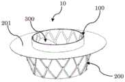
图1是根据本发明示例性实施方式的处于展开状态的用于修复或替换心脏的自体瓣膜的移植物的立体图。FIG. 1 is a perspective view of a graft for repairing or replacing a native valve of the heart in a deployed state according to an exemplary embodiment of the present invention.
图2是图1所示的移植物的主视图,其省略了外支架的覆膜。FIG. 2 is a front view of the graft shown in FIG. 1 , omitting the covering of the outer stent.
图3是图1所示的移植物的俯视图。Figure 3 is a top view of the graft shown in Figure 1 .
图4是图1所示的移植物的仰视立体图。FIG. 4 is a bottom perspective view of the implant shown in FIG. 1 .
图5是图1所示的移植物的仰视图。Figure 5 is a bottom view of the graft shown in Figure 1 .
图6示意性地示出了根据本发明示例性实施方式的用于制造用于修复或替换心脏的自体瓣膜的移植物的内支架骨架。Fig. 6 schematically shows an inner stent skeleton for manufacturing a graft for repairing or replacing a native valve of the heart according to an exemplary embodiment of the present invention.
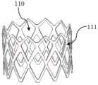
图7是从心房侧示出在使用图6所示的骨架构成的内支架内部设置人工瓣叶的内支架立体图。Fig. 7 is a perspective view showing an inner stent in which artificial valve leaflets are placed inside the inner stent constructed using the framework shown in Fig. 6 from the atrium side.
图8是从心室侧示出在使用图6所示的骨架构成的内支架内部设置人工瓣叶的内支架立体图。Fig. 8 is a perspective view of the inner stent in which artificial valve leaflets are placed inside the inner stent constructed using the framework shown in Fig. 6, from the ventricle side.
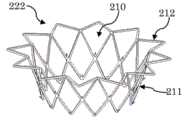
图9示意性地示出了根据本发明示例性实施方式的用于制造用于修复或替换心脏的自体瓣膜的移植物的外支架骨架。Fig. 9 schematically shows an outer stent skeleton for manufacturing a graft for repairing or replacing a native valve of the heart according to an exemplary embodiment of the present invention.
具体实施方式Detailed ways
为了便于理解本发明技术方案的各个方面、特征以及优点,下面结合附图对本发明进行具体描述。应当理解,下述的各种实施方式只用于举例说明,而非用于限制本发明的保护范围。In order to facilitate the understanding of various aspects, features and advantages of the technical solutions of the present invention, the present invention will be specifically described below in conjunction with the accompanying drawings. It should be understood that the various embodiments described below are only for illustration, rather than limiting the protection scope of the present invention.
在本文中,本领域技术人员应当理解,术语“心室侧”是指移植物朝向、靠近、或位于心室的一侧,术语“心房侧”是指移植物朝向、靠近、或位于心房的一侧。Herein, those skilled in the art should understand that the term "ventricular side" refers to the side of the graft facing, close to, or located in the ventricle, and the term "atrial side" refers to the side of the graft facing, close to, or located in the atrium. .
图1至图5示出了根据本发明示例性实施方式的用于修复或替换心脏的自体瓣膜的移植物。其中,所述自体瓣膜包括瓣环、连接到所述瓣环的自体瓣叶以及瓣下结构。在本发明的一种示例性实施方式中,所述移植物可以用于修复或替换心脏的二尖瓣,二尖瓣主要包含三种结构:二尖瓣叶、二尖瓣环、腱索和乳头肌。1 to 5 illustrate a graft for repairing or replacing a native valve of the heart according to an exemplary embodiment of the present invention. Wherein, the native valve includes a valve ring, native valve leaflets connected to the valve ring, and subvalvular structures. In an exemplary embodiment of the present invention, the graft can be used to repair or replace the mitral valve of the heart, and the mitral valve mainly includes three structures: mitral valve leaflets, mitral valve ring, chordae and papillary muscles.
根据本发明的示例性实施方式,所述移植物至少具有用于输送的压缩状态和用于部署的展开状态。图1示出了处于展开状态的移植物10。所述移植物10可以包括:内支架100(即第一覆膜支架)、外支架200(即第二覆膜支架)以及人工瓣叶300。在本发明的一种实施方式中,如图6至图8所示,通过在可折叠的内支架骨架111上覆膜构成内支架100。在展开状态下,内支架100大致呈圆筒状,并且具有第一内部通道110,在所述第一内部通道110内固定连接有用于替换自体瓣叶(例如,二尖瓣叶)的人工瓣叶300。在本发明的一些实施方式中,所述人工瓣叶由三叶牛心包、猪心包、猪颈静脉瓣膜、猪主动脉瓣、驴心包瓣三叶瓣膜等生物材料制成。在本发明的一种实施方式中,如图9所示,通过在可折叠的外支架骨架222上覆膜而构成外支架200,其中,外支架骨架222包括展开大致呈圆台形的骨架211和自骨架211的大径端横向弯折的骨架212。骨架211通过覆膜形成外支架200的主体部,该主体部具有第二内部通道210,返回参考图1和图2,内支架100位于所述第二内部通道210内并且与所述外支架200固定连接,并且,在展开状态下,所述第二内部通道210心房侧的端部口径大于其心室侧的端部口径。此外,骨架212通过覆膜形成凸缘201,在展开状态下,所述凸缘201自所述外支架200的心房端径向延伸,所述凸缘201适于位于所述瓣环(例如,二尖瓣环)的心房侧。所述外支架200适于在压缩状态下穿过所述瓣环以及在展开状态下锚定在所述瓣环和瓣下结构(例如,腱索和乳头肌)。移植物10为采用内支架100和外支架200构成的双层支架结构,可以增加其锚定力,提高稳定性。在本发明的示例性实施方式中,制作支架的骨架可以为自膨支架和球扩支架。制作支架的覆膜材料可以包括涤纶及PTFE(聚四氟乙烯)等。According to an exemplary embodiment of the present invention, the graft has at least a compressed state for delivery and an expanded state for deployment. Figure 1 shows the
在本发明各实施方式中,在展开状态下,内支架100大致呈圆筒状,其口径可以为18-34mm。外支架200的内径(即第二内部通道210)从心室侧朝心房侧逐渐变大,构成为喇叭状、圆台状或锥形结构,从而,可以预防并减少瓣周漏的发生。其中,所述外支架200的心室侧的端部口径D0可以为20-36mm,心房侧端部口径D1可以为30-50mm,外支架200的长度可为10-40mm,心房侧凸缘外径D2为32-60mm。在本发明的示例性实施方式中,所述内支架100的口径可以为26mm,所述外支架200的凸缘201的外径D2为50mm,其心房侧的端部口径D1为34mm,心室侧的端部口径D0可以为28mm。该尺寸的选取考虑到人体解剖学的特点,如人体的二尖瓣瓣环的口径在40mm左右。In various embodiments of the present invention, in the unfolded state, the
在可选的实施方式中,内支架100可以与外支架200可具有相同的形状,例如,同为喇叭状。在其他实施方式中,外支架200也可以构成为其他形状,例如喇叭状的D型。In an optional embodiment, the
在本发明的一些实施方式中,所述外支架200的内壁与所述内支架100的外壁之间夹角为5-45°。在本发明的示例性实施方式中,所述外支架200的内壁与所述内支架100的外壁之间夹角为15°,该值的选取考虑人体解剖学的特点及内支架和外支架的口径大小。由此,通过优化外支架与内支架的夹角,以预防并减少瓣周漏的发生。In some embodiments of the present invention, the angle between the inner wall of the
在本发明的示例性实施方式中,如图2和图4所示,外支架200的心室侧端部与内支架100的心室侧端部两者的骨架固定连接,例如,可为刚性连接(例如,铆接,焊接),也可为柔性连接(例如,绳连接)。并且,如图1和图3所示,外支架200的凸缘201的覆膜与内支架100的覆膜连接,由此,相当于缝上去了一个盖子,覆膜包绕凸缘201的同时填补了内外支架之间的空隙。相连部位用覆膜相连的优势在于可有效减缓产品植入人体后的瓣周漏的量问题。在可选的实施方式中,外支架200的心室侧端部的覆膜与内支架100的心室侧端部的覆膜连接,并且外支架200的凸缘201的覆膜与内支架100的覆膜连接。In an exemplary embodiment of the present invention, as shown in FIG. 2 and FIG. 4 , the skeleton of the ventricular side end of the
在本发明的各实施方式中,内支架100包括位于外支架200的第二内部通道内的第一部分和从所述第二内部通道朝心房侧延伸出的第二部分。所述内支架100的第一部分为从其心室侧端部至对应于所述外支架200的凸缘201的位置的一段,即,位于所述外支架200内部的一段;其第二部分为从所述对应于所述外支架200的凸缘的位置至其心房侧端部的一段,即位于所述外支架200外部的一段。在本发明的示例性实施方式中,所述内支架的所述第一部分的长度H1与其第二部分的长度H2之比可以为1:1到4:1之间。所述第一部分的长度H1可以为10-40mm,其第二部分的长度H2可以为5-15mm。在本发明的示例性实施方式中,H1可以为15mm,H2可以为5mm。在本发明的可选实施方式中,H1可以为15mm,H2可以为5mm。在本发明的其他实施方式中,H1可以为10mm,H2可以为5mm,该值的选取考虑到内支架口径的大小,口径越小,高度越小。在本发明的一些实施方式中,内支架100的心室侧端部距离所述外支架200的凸缘201的长度可以为:0-15mm。相比于现有移植物将内外支架均设于心室侧,本发明实施方式通过降低内支架在心室侧的高度(即H1),预防LOVTO(左室流出道梗阻)的发生。In various embodiments of the present invention, the
在本发明的可选实施方式中,所述内支架100的所述第二部分可以为未覆膜的裸支架,由此进一步降低心室侧高度,预防LOVTO(左室流出道梗阻)的发生。In an optional embodiment of the present invention, the second part of the
在本发明的各实施方式中,所述外支架200的心房侧的端部至其心室侧的端部的距离(即外支架的长度)可以为10-30mm。外支架的长度不足10mm,不利于人工瓣膜的缝制;超过30mm,则支架会与左室流出道出现干涉。在本发明的示例性实施方式中,所述外支架200的心房侧的端部至其心室侧的端部的距离优选为15mm。In various embodiments of the present invention, the distance from the end of the
在本发明的示例性实施方式中,外支架200的外周设有适于连接所述瓣下结构的倒刺202。所述倒刺的长度为0.5-5mm,优选为1.5mm。由此,可以增加其锚定力,提高稳定性。在本发明的一些实施方式中,倒刺202可以设置在外支架200的骨架上,例如,如图9所示,在骨架211各丝相互交联的位置设有倒刺。在本发明的可选实施方式中,可以在骨架211周向上同一圆周设置多个倒刺。In an exemplary embodiment of the present invention, the outer periphery of the
在本发明的可选实施方式中,外支架200的凸缘201面向心室侧的表面也可设有适于连接所述瓣环的倒刺,所述倒刺的长度为0.5-5mm,优选2mm。由此,进一步可以增加其锚定力,提高稳定性。在本发明的示例性实施方式中,所述倒刺可以设置在凸缘201的骨架上。由此,可以进一步增加其锚定力,提高稳定性。In an optional embodiment of the present invention, the surface of the
本领技术人员应当理解,以上所公开的仅为本发明的实施方式而已,当然不能以此来限定本发明之权利范围,依本发明实施方式所作的等同变化,仍属本发明权利要求所涵盖的范围。Those skilled in the art should understand that what is disclosed above is only the embodiment of the present invention, and of course it cannot limit the scope of rights of the present invention. The equivalent changes made according to the embodiments of the present invention are still covered by the claims of the present invention. scope.
Claims (19)
Priority Applications (1)
| Application Number | Priority Date | Filing Date | Title |
|---|---|---|---|
| CN202010401941.1ACN111643223B (en) | 2020-05-13 | 2020-05-13 | Grafts to repair or replace the heart's own valves |
Applications Claiming Priority (1)
| Application Number | Priority Date | Filing Date | Title |
|---|---|---|---|
| CN202010401941.1ACN111643223B (en) | 2020-05-13 | 2020-05-13 | Grafts to repair or replace the heart's own valves |
Publications (2)
| Publication Number | Publication Date |
|---|---|
| CN111643223A CN111643223A (en) | 2020-09-11 |
| CN111643223Btrue CN111643223B (en) | 2023-04-14 |
Family
ID=72348249
Family Applications (1)
| Application Number | Title | Priority Date | Filing Date |
|---|---|---|---|
| CN202010401941.1AActiveCN111643223B (en) | 2020-05-13 | 2020-05-13 | Grafts to repair or replace the heart's own valves |
Country Status (1)
| Country | Link |
|---|---|
| CN (1) | CN111643223B (en) |
Families Citing this family (6)
| Publication number | Priority date | Publication date | Assignee | Title |
|---|---|---|---|---|
| CN113081394B (en)* | 2021-04-12 | 2022-08-05 | 苏州茵络医疗器械有限公司 | Artificial heart valve |
| WO2022236929A1 (en)* | 2021-05-14 | 2022-11-17 | 上海臻亿医疗科技有限公司 | Heart valve prosthesis apparatus |
| CN114271995B (en)* | 2022-01-17 | 2023-06-30 | 上海捍宇医疗科技股份有限公司 | Interventional prosthetic valve by apex anchoring |
| WO2024000835A1 (en)* | 2022-06-30 | 2024-01-04 | 上海翰凌医疗器械有限公司 | Transcatheter valve replacement device and stent thereof |
| CN117100458A (en)* | 2023-08-24 | 2023-11-24 | 上海诠昕医疗科技有限公司 | Valve prosthesis device with selectively distributed barbs |
| CN117159228B (en)* | 2023-08-24 | 2025-04-04 | 上海诠昕医疗科技有限公司 | A valve prosthesis device with segmented conical structure |
Family Cites Families (7)
| Publication number | Priority date | Publication date | Assignee | Title |
|---|---|---|---|---|
| CN102292053A (en)* | 2008-09-29 | 2011-12-21 | 卡迪尔克阀门技术公司 | Heart valve |
| EP3613383B1 (en)* | 2008-11-21 | 2023-08-30 | Percutaneous Cardiovascular Solutions Pty Limited | Heart valve prosthesis |
| JP6133309B2 (en)* | 2011-10-19 | 2017-05-24 | トゥエルヴ, インコーポレイテッド | Prosthetic heart valve device |
| CN109091272B (en)* | 2015-11-06 | 2021-10-22 | 麦克尔有限公司 | mitral valve prosthesis |
| US10492907B2 (en)* | 2016-11-07 | 2019-12-03 | Medtronic Vascular, Inc. | Valve delivery system |
| US10368988B2 (en)* | 2016-11-09 | 2019-08-06 | Medtronic Vascular, Inc. | Valve delivery system having an integral displacement component for managing chordae tendineae in situ and methods of use thereof |
| CN111067666B (en)* | 2019-12-17 | 2021-08-27 | 宁波健世科技股份有限公司 | Transcatheter valve replacement system |
- 2020
- 2020-05-13CNCN202010401941.1Apatent/CN111643223B/enactiveActive
Also Published As
| Publication number | Publication date |
|---|---|
| CN111643223A (en) | 2020-09-11 |
Similar Documents
| Publication | Publication Date | Title |
|---|---|---|
| CN111643223B (en) | Grafts to repair or replace the heart's own valves | |
| US12268593B2 (en) | Valve anchor and installation method | |
| US11833038B2 (en) | Valve prosthesis and method for delivery | |
| US10945841B2 (en) | Valve prosthesis and method for delivery | |
| US10548723B2 (en) | Prosthetic heart valve devices and methods of valve replacement | |
| US10660750B2 (en) | Heart valve assembly systems and methods | |
| CN107613907B (en) | heart valve components | |
| JP2022120041A (en) | Expandable frames and paravalvular leak mitigation systems for implantable prosthetic heart valve devices | |
| US20160220366A1 (en) | Vascular implant | |
| TW202017538A (en) | Stent loading device with fluid reservoir | |
| CN117100458A (en) | Valve prosthesis device with selectively distributed barbs | |
| CN117159228A (en) | Valve prosthesis device with sectional conical structure | |
| CN116492110A (en) | Valve support and prosthetic valve assembly | |
| US20200253729A1 (en) | Universal heart valve device | |
| HK1249393B (en) | Heart valve assembly |
Legal Events
| Date | Code | Title | Description |
|---|---|---|---|
| PB01 | Publication | ||
| PB01 | Publication | ||
| SE01 | Entry into force of request for substantive examination | ||
| SE01 | Entry into force of request for substantive examination | ||
| CB02 | Change of applicant information | Address after:200433 No. 168 Changhai Road, Shanghai, Yangpu District Applicant after:The First Affiliated Hospital of Navy Military Medical University of PLA Address before:200433 No. 168 Changhai Road, Shanghai, Yangpu District Applicant before:SHANGHAI CHANGHAI Hospital | |
| CB02 | Change of applicant information | ||
| TA01 | Transfer of patent application right | Effective date of registration:20210827 Address after:200433 No. 168 Changhai Road, Shanghai, Yangpu District Applicant after:The First Affiliated Hospital of Navy Military Medical University of PLA Applicant after:Beijing Xinwei Medical Technology Co.,Ltd. Address before:200433 No. 168 Changhai Road, Shanghai, Yangpu District Applicant before:The First Affiliated Hospital of Navy Military Medical University of PLA | |
| TA01 | Transfer of patent application right | ||
| GR01 | Patent grant | ||
| GR01 | Patent grant |