CN111630342B - Gap detection method and system for visual welding system - Google Patents
Gap detection method and system for visual welding systemDownload PDFInfo
- Publication number
- CN111630342B CN111630342BCN201880087341.3ACN201880087341ACN111630342BCN 111630342 BCN111630342 BCN 111630342BCN 201880087341 ACN201880087341 ACN 201880087341ACN 111630342 BCN111630342 BCN 111630342B
- Authority
- CN
- China
- Prior art keywords
- metal parts
- gap
- image
- point
- visual inspection
- Prior art date
- Legal status (The legal status is an assumption and is not a legal conclusion. Google has not performed a legal analysis and makes no representation as to the accuracy of the status listed.)
- Active
Links
Images


Classifications
- G—PHYSICS
- G01—MEASURING; TESTING
- G01B—MEASURING LENGTH, THICKNESS OR SIMILAR LINEAR DIMENSIONS; MEASURING ANGLES; MEASURING AREAS; MEASURING IRREGULARITIES OF SURFACES OR CONTOURS
- G01B11/00—Measuring arrangements characterised by the use of optical techniques
- G01B11/14—Measuring arrangements characterised by the use of optical techniques for measuring distance or clearance between spaced objects or spaced apertures
Landscapes
- Physics & Mathematics (AREA)
- General Physics & Mathematics (AREA)
- Length Measuring Devices By Optical Means (AREA)
Abstract
Translated fromChinese
Description
Translated fromChinese技术领域technical field
本申请涉及到缝隙检测领域,特别是涉及一种视觉焊接系统的缝隙检测方法以及系统。The present application relates to the field of gap detection, and in particular, to a gap detection method and system for a visual welding system.
背景技术Background technique
在焊接领域中,如何检测待焊接金属间是否存在缝隙尤为重要,但是现如今的单相机的视觉系统难以对需要焊接的立体金属间存在的缝隙进行有效的检测,同时,在现有技术下,空间以及3D视觉系统比较昂贵,难以实现量产,因此引用了2D视觉系统,但是一般的光用2D视觉系统在查看金属存在诸多的问题;例如:视觉角度、金属表面的反光不均匀、金属与周围环境的相似灰度不好区分等。In the field of welding, how to detect whether there is a gap between the metals to be welded is particularly important, but the current single-camera vision system is difficult to effectively detect the gap between the three-dimensional metals to be welded. At the same time, under the existing technology, Space and 3D vision systems are expensive and difficult to achieve mass production. Therefore, 2D vision systems are used. However, there are many problems in viewing metals with general light 2D vision systems; for example, viewing angles, uneven reflections on metal surfaces, and Similar grayscales of the surrounding environment are not easy to distinguish, etc.
发明内容SUMMARY OF THE INVENTION
本申请提供一种视觉焊接系统的缝隙检测方法以及系统,以解决如今缝隙检测难度较大或成本较高的问题。The present application provides a gap detection method and system for a visual welding system, so as to solve the problem that gap detection is difficult or costly.
本申请采用的一个技术方案是:提供一种视觉焊接系统的缝隙检测方法,包括步骤:通过视觉检测方式确定待焊接区域的两个金属部件的排布关系;当两个金属部件为空间异面设置时,向两个金属部件投射点状形激光图案;根据点状形激光图案以结构光检测方式确定两个金属部件之间的缝隙信息。A technical solution adopted in the present application is to provide a method for detecting gaps in a visual welding system, comprising the steps of: determining the arrangement relationship of two metal parts in the area to be welded by visual inspection; When setting, project a dot-shaped laser pattern to the two metal parts; according to the dot-shaped laser pattern, the gap information between the two metal parts is determined in a structured light detection manner.
为解决上述技术问题,本申请采用的另一个技术方案是:一种视觉焊接系统,包括视觉检测系统,用于通过视觉检测方式确定待焊接区域的两个金属部件的排布关系;激光投射装置,用于对确定排布方式为空间异面设置的两个金属部件投射点状激光图案;所述视觉检测系统进一步根据所述点状图案以结构光检测方式确定所述两个金属部件之间的缝隙信息。In order to solve the above technical problems, another technical solution adopted in the present application is: a visual welding system, including a visual inspection system, for determining the arrangement relationship of two metal parts in the area to be welded by visual inspection; a laser projection device , which is used to project a dot-shaped laser pattern on two metal parts whose arrangement is determined to be spatially different; the visual inspection system further determines the distance between the two metal parts by structured light detection according to the dot-shaped pattern. gap information.
为解决上述技术问题,本申请采用的另一个技术方案是:一种计算机存储介质,存储有能够实现上述任一方法的程序文件。In order to solve the above technical problem, another technical solution adopted in the present application is: a computer storage medium storing a program file capable of implementing any of the above methods.
本申请的有益效果是:一种视觉焊接系统的缝隙检测方法以及系统,通过视觉检测方式确定待焊接区域的两个金属部件的排布关系,当确定两个金属部件为空间异面设置时,向两个金属部件投射点状形激光图案,并根据点状形激光图案以结构光检测方式确定两个金属部件之间的缝隙信息,从而可以实现对焊接区域的两个金属部件进行缝隙检测。The beneficial effects of the present application are: a gap detection method and system for a visual welding system, the arrangement relationship of two metal parts in a to-be-welded area is determined by a visual detection method, and when it is determined that the two metal parts are arranged on different planes in space, Projecting a dot-shaped laser pattern to two metal parts, and determining the gap information between the two metal parts by structured light detection according to the dot-shaped laser pattern, so that the gap detection of the two metal parts in the welding area can be realized.
附图说明Description of drawings
图1是本申请视觉焊接系统的缝隙检测的方法第一实施方式的流程示意图;1 is a schematic flowchart of a first embodiment of a method for gap detection in a visual welding system of the present application;
图2是本申请视觉焊接系统的缝隙检测的方法第二实施方式的流程示意图;FIG. 2 is a schematic flowchart of the second embodiment of the method for gap detection of the visual welding system of the present application;
图3是本申请视觉焊接系统的缝隙检测的方法第三实施方式的流程示意图;3 is a schematic flowchart of a third embodiment of the method for gap detection of the visual welding system of the present application;
图4是本申请视觉焊接系统的缝隙检测的方法第四实施方式的流程示意图;4 is a schematic flowchart of a fourth embodiment of the method for gap detection of the visual welding system of the present application;
图5是图3以及图4实施例的一个具体实施例示意图;Fig. 5 is a schematic diagram of a specific embodiment of the embodiment of Fig. 3 and Fig. 4;
图6是图5所示具体实施例中坐标计算的简单原理示意图;Fig. 6 is the simple principle schematic diagram of coordinate calculation in the specific embodiment shown in Fig. 5;
图7是图5所示具体实施例中坐标计算的另简单原理示意图;Fig. 7 is another simple principle schematic diagram of coordinate calculation in the specific embodiment shown in Fig. 5;
图8是本申请视觉焊接系统的一实施方式的结构示意图;8 is a schematic structural diagram of an embodiment of the visual welding system of the present application;
图9是本申请计算机存储介质的一实施方式的结构示意图。FIG. 9 is a schematic structural diagram of an embodiment of a computer storage medium of the present application.
具体实施方式Detailed ways
下面将结合本申请实施例中的附图,对本申请实施例中的技术方案进行清楚、完整地描述,显然,所描述的实施例仅是本申请的一部分实施例,而不是全部的实施例。基于本申请中的实施例,本领域普通技术人员在没有做出创造性劳动前提下所获得的所有其他实施例,都属于本申请保护的范围。The technical solutions in the embodiments of the present application will be clearly and completely described below with reference to the drawings in the embodiments of the present application. Obviously, the described embodiments are only a part of the embodiments of the present application, but not all of the embodiments. Based on the embodiments in the present application, all other embodiments obtained by those of ordinary skill in the art without creative efforts shall fall within the protection scope of the present application.
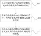
请参阅图1,图1是本申请视觉焊接系统的缝隙检测方法第一实施方式的流程示意图,具体的缝隙检测方法包括以下步骤:Please refer to FIG. 1. FIG. 1 is a schematic flowchart of the first embodiment of the gap detection method of the visual welding system of the present application. The specific gap detection method includes the following steps:
S11,通过视觉检测方式确定焊接区域的两个金属部件的排布关系。S11, the arrangement relationship of the two metal parts in the welding area is determined by visual inspection.
在本实施例中,由于对不同的排布的金属部件采用的是不同的焊接方法,所以首先要对焊接区域的两个金属部件进行检测,具体是通过视觉检测的方式对两个金属进行图像采集、图像识别以及处理。In this embodiment, since different welding methods are used for different arranged metal parts, firstly, the two metal parts in the welding area must be inspected, specifically, the two metals are imaged by visual inspection. Acquisition, image recognition, and processing.
在具体的实施例中,两个金属部件的排布方式分别是空间异面以及空间共面设置。In a specific embodiment, the two metal components are arranged in a spatially different plane and a spatially coplanar arrangement, respectively.
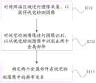
参阅图2,图2是本申请视觉焊接系统的缝隙检测方法第二实施方式的流程示意图,且是步骤S11的子实施例,具体包括如下步骤:Referring to FIG. 2, FIG. 2 is a schematic flowchart of the second embodiment of the gap detection method of the visual welding system of the present application, and is a sub-example of step S11, which specifically includes the following steps:
S111,对待焊接区域进行图像采集,以获得视觉检测图像。S111, image acquisition of the area to be welded is performed to obtain a visual inspection image.
在本实施例中,采用是自动化的方法对待焊接区域进行检测,首先需要进行图像采集,主要是通过机器对整个焊接区域进行图像采集,从而获得焊接区域的两个金属部件的视觉检测图像。In this embodiment, an automated method is used to detect the to-be-welded area. First, image acquisition is required, mainly through image acquisition of the entire welding area by a machine, so as to obtain visual inspection images of two metal parts in the welded area.
S112,对视觉检测图像进行图像识别,以从视觉检测图像中识别出两个金属部件。S112: Perform image recognition on the visual inspection image to identify two metal parts from the visual inspection image.
本申请主要通过将激光图案投射到金属部件表面从而完成缝隙检测,需要确定两个金属部件的位置信息,包括具体的坐标、位置排布等等,从而需要对含有金属部件的视觉检测图像进行识别,识别出金属部件。This application mainly completes gap detection by projecting a laser pattern on the surface of metal parts. It is necessary to determine the position information of two metal parts, including specific coordinates, position arrangement, etc., so it is necessary to identify the visual inspection images containing metal parts. , metal parts are identified.
S113,确定两个金属部件在视觉检测图像中的排布关系。S113, determine the arrangement relationship of the two metal parts in the visual inspection image.
在本申请中,由于对于不同的金属焊接方式采取不同的检测方式,即对于金属的不同排布方式采用不同的检测方式,因此通过识别后,对两个金属部件的位置信息进行处理,从而得出其位置关系。In this application, since different detection methods are adopted for different metal welding methods, that is, different detection methods are adopted for different metal arrangements, after identification, the position information of the two metal parts is processed to obtain out of its positional relationship.
当测视觉检测图像中两个金属部件的排布方式为空间异面的时候,则采用结构光检测方式;当两个金属部件的排布方式为空间共面的时候,则采用亮度检测方式。When the arrangement of the two metal parts in the visual inspection image is spatially different, the structured light detection method is used; when the arrangement of the two metal parts is spatially coplanar, the brightness detection method is used.
上述实施方式中,通过对焊接区域进行图像采集,并识别所采集到的视觉检测图像中的两个金属部件,随后确定两个金属部件的排布关系,从而完成对焊接区域两个金属的视觉检测与识别,并通过排布方式确定接下来使用的检测方式。In the above-mentioned embodiment, by collecting images of the welding area, identifying the two metal parts in the collected visual inspection images, and then determining the arrangement relationship of the two metal parts, the vision of the two metals in the welding area is completed. Detect and identify, and determine the next detection method through the arrangement.
S13,当两个金属部件为空间异面设置时,采用结构光检测方式进行检测。S13, when the two metal parts are arranged on different planes in space, a structured light detection method is used for detection.
当检测出的两个金属部件为空间异面设置时,则采用结构光检测方式,在本实施例中,具体是通过向两个金属部件投射点状激光形图案,然后进行图像的采集、识别以及处理确定是否两个金属部件存在缝隙,其中缝隙信息包括是否存在缝隙及缝隙的大小信息。When the detected two metal parts are arranged on different planes in space, the structured light detection method is adopted. In this embodiment, the point-like laser pattern is projected onto the two metal parts, and then the image is collected and recognized. And processing determines whether there is a gap between the two metal parts, wherein the gap information includes whether there is a gap and size information of the gap.
上述实施方式中,通过对两个金属部件进行排布检测,再通过不同检测结果确定不同的缝隙检测方式。In the above-mentioned embodiment, the arrangement detection of the two metal components is performed, and then different gap detection methods are determined according to different detection results.
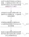
参阅图3,图3是本申请视觉焊接系统的缝隙检测方法第三实施方式的流程示意图,在本实施例中,是通过在两个金属部件表面上形成相应的激光图案,继而得到投射到金属部件上的激光图案的空间位置信息,从而得到与激光图案对应的金属部件的位置,最后确定出两个金属之间的缝隙信息,其中缝隙信息包括是否存在缝隙以及缝隙的大小信息。具体包括如下步骤:Referring to FIG. 3, FIG. 3 is a schematic flowchart of the third embodiment of the gap detection method of the visual welding system of the present application. In this embodiment, the corresponding laser patterns are formed on the surfaces of two metal parts, and then the projection onto the metal parts is obtained. The spatial position information of the laser pattern on the component is obtained to obtain the position of the metal component corresponding to the laser pattern, and finally the gap information between the two metals is determined, wherein the gap information includes whether there is a gap and the size of the gap. Specifically include the following steps:
S131,向两个金属部件投射点状形激光图案,以使得分别作用于两个金属部件的表面上的点状激光图案的数量不少于两个。S131 , projecting a spot-shaped laser pattern to the two metal parts, so that the number of spot-shaped laser patterns respectively acting on the surfaces of the two metal parts is not less than two.
在本实施例中,需要向两个金属部件投射点状形的激光图案,包括第一激光图案与第二激光图案,其中,至少有两个点状激光图案作用于两个处于空间异面设置的金属部件的其中一个金属部件表面上,形成一个激光图案,至少有两个点状激光图案作用于两个金属部件中的另外一个金属部件表面上,同样形成相应激光图案。In this embodiment, it is necessary to project a point-shaped laser pattern on two metal parts, including a first laser pattern and a second laser pattern, wherein at least two point-shaped laser patterns act on the two metal parts arranged on different planes in space A laser pattern is formed on the surface of one of the metal parts of the metal parts, and at least two point-shaped laser patterns act on the surface of the other metal part of the two metal parts, and corresponding laser patterns are also formed.
S132,对投射有点状形激光图案的两个金属部件进行图像采集,以获取缝隙检测图像。S132 , image acquisition is performed on the two metal parts projecting a dot-shaped laser pattern to obtain a gap detection image.
在向两个金属部件投射点状形激光图案并在分别两个金属部件的表面上形成相关的激光图案后,需要去采集获取缝隙检测图像,其中,缝隙检测图像中相对视觉检测图像多了相应的激光图案。After projecting a dot-shaped laser pattern on the two metal parts and forming the relevant laser patterns on the surfaces of the two metal parts, it is necessary to collect and obtain a gap detection image, wherein the gap detection image is more corresponding to the visual detection image than the visual detection image. laser pattern.
S133,对缝隙检测图像进行图像识别,以从缝隙检测图像中识别出点状形激光图案。S133 , performing image recognition on the gap detection image, so as to identify a point-shaped laser pattern from the gap detection image.
在本实施例中,由于点状形激光图案作用于两个金属部件的表面并形成相应的激光图案,即点状形激光图案的空间位置信息其实就是相当于这个点状形激光图案所在的金属部件的空间位置信息,首先需要将缝隙检测图像中激光图案识别出来。In this embodiment, since the dot-shaped laser pattern acts on the surfaces of the two metal parts and forms corresponding laser patterns, that is, the spatial position information of the dot-shaped laser pattern is actually equivalent to the metal where the dot-shaped laser pattern is located. To obtain the spatial position information of the part, it is first necessary to identify the laser pattern in the gap detection image.
S134,根据点状形激光图案在缝隙检测图像中的位置信息确定两个金属部件之间的缝隙信息。S134: Determine the gap information between the two metal parts according to the position information of the dot-shaped laser pattern in the gap detection image.
从缝隙检测图像检测出点状形激光图案后,通过计算得到点状形激光图案的位置信息,继而得到所对应的金属部件的位置信息,然后通过比对、确定得到两个金属部件之间的缝隙信息。After detecting the point-shaped laser pattern from the gap detection image, the position information of the point-shaped laser pattern is obtained by calculation, and then the position information of the corresponding metal part is obtained, and then the difference between the two metal parts is obtained by comparison and determination. gap information.
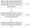
参阅图4,图4是本申请视觉焊接系统的缝隙检测方法第四实施方式的流程示意图,且图4是图3步骤S134的子实施例,通过对识别出来的点状形激光图案进行选点、确定直线、计算距离以及比对来得到两个金属部件是否存在缝隙,具体包括如下步骤:Referring to FIG. 4, FIG. 4 is a schematic flowchart of the fourth embodiment of the gap detection method of the visual welding system of the present application, and FIG. 4 is a sub-example of step S134 in FIG. , determine the straight line, calculate the distance and compare to get whether there is a gap between the two metal parts, which includes the following steps:
S1341,根据点状形激光图案在缝隙检测图像中的位置信息分别确定两个金属部件的表面上的至少两个参考点的空间坐标。S1341 , respectively determining the spatial coordinates of at least two reference points on the surfaces of the two metal parts according to the position information of the dot-shaped laser pattern in the gap detection image.
在上述的实施例中已经说明,作用于金属部件上的激光图案的位置相当于其所在的金属部件的位置信息,即只要计算点状形激光图案所在的直线的空间位置信息,即金属部件的空间位置信息,具体的,计算一条直线需要至少两点的信息。具体的,根据激光图案在缝隙检测图像中的位置信息,从而得到其中激光图案中至少两个点的空间坐标。In the above-mentioned embodiments, it has been explained that the position of the laser pattern acting on the metal part is equivalent to the position information of the metal part where it is located, that is, as long as the spatial position information of the straight line where the dot-shaped laser pattern is located is calculated, that is, the position of the metal part is Spatial position information, specifically, calculating a straight line requires information of at least two points. Specifically, according to the position information of the laser pattern in the gap detection image, the spatial coordinates of at least two points in the laser pattern are obtained.
请进一步参阅图5,图5是图3以及图4实施例的一个具体实施例示意图,其中,在本实施例中,采用的是通过投射点状激光对两个金属部件进行检测。Please further refer to FIG. 5 , which is a schematic diagram of a specific embodiment of the embodiments of FIGS. 3 and 4 , wherein, in this embodiment, two metal parts are detected by projecting a spot laser.
其中,焊接区域包括了两个金属部件分别是M以及N,通过向两个金属部件投射点状激光,使得至少两个点状激光图案作用于金属部件M表面上,在本实施例中,采用最优原则,只形成两个点状激光图案,分别是点状激光E以及点状激光G,同样的,在金属部件N表面形成点状激光F以及点状激光H。The welding area includes two metal parts M and N, respectively. By projecting point lasers to the two metal parts, at least two point laser patterns act on the surface of the metal part M. In this embodiment, using The optimal principle is to form only two point laser patterns, namely point laser E and point laser G. Similarly, point laser F and point laser H are formed on the surface of metal part N.
在具体的实施例中,从两个金属部件上的激光图案上分别取两点,根据结构光的检测原理,一方面可以通过图像确定所取点的横纵轴坐标,一方面根据图像的偏移角度以及距离信息来确定所取点的竖轴坐标,从而可以得出所取点的空间坐标,其中金属部件M取E以及G点,坐标分别是是E(x1,y1,z1),G(x2,y2,z2),所对应的直线为L1;金属部件N取F以及H点,其坐标是F(X1,Y1,Z1),H(X2,Y2,Z2),所对应的直线为L2,即金属部件M对应直线L1,金属部件N对应直线L2。In a specific embodiment, two points are respectively taken from the laser patterns on the two metal parts. According to the detection principle of structured light, on the one hand, the horizontal and vertical axis coordinates of the taken points can be determined by the image, and on the other hand, according to the deviation of the image Shift angle and distance information to determine the vertical axis coordinates of the point taken, so that the spatial coordinates of the point can be obtained, wherein the metal part M takes points E and G, and the coordinates are E(x1, y1, z1), G( x2, y2, z2), the corresponding straight line is L1; the metal part N takes points F and H, whose coordinates are F(X1, Y1, Z1), H(X2, Y2, Z2), and the corresponding straight line is L2 That is, the metal part M corresponds to the straight line L1, and the metal part N corresponds to the straight line L2.
上述所述的通过2D摄像头进行检测其点的三维坐标具体可以通过如下方法:The above-mentioned three-dimensional coordinates of the points detected by the 2D camera can be detected by the following methods:
如图6,光源21的激光打在金属M表面形成一个激光图案,取其中一个落点m,图像传感器11与金属M所在的平面的交点为Q点,因此m、图像传感器11、Q点一起构成一个直角三角形,其中一个直角为θ1,这里是图像传感器11在进行采集m点时候的偏移角,是已知的,其L1为m点到Q点的偏移距离,可以通过图像采集后的两点距离进行得出,因此在一个直角三角形中,已知一条直角边一个非直角的角度值,根据三角函数可以得出另外一个边的距离值,即图像传感器21到Q点的距离,建立坐标轴,可以得到其横纵竖坐标。As shown in Fig. 6, the laser of the
同理,对于金属N而言,其落点为n,交点为P,偏移角为θ2,偏移距离为L2,也可以得出图像传感器21到P点的距离。Similarly, for metal N, its drop point is n, the intersection point is P, the offset angle is θ2, and the offset distance is L2, and the distance from the
在其他实施例中,也可以是垂直向金属部件投射激光图案,并在金属部件取一点P,此时光源、摄像机、P点构成一个直角三角形,同样的采用三角函数的方法进行计算,此时偏移位移为光源与摄像机的相对距离。In other embodiments, the laser pattern can also be projected vertically to the metal part, and a point P is taken on the metal part. At this time, the light source, the camera, and the point P form a right triangle, and the same trigonometric function is used for calculation. The offset displacement is the relative distance of the light source from the camera.
在又一实施例中,可以采用构建多个平面及坐标系的方法进行获取,如图7所示,光源21在向金属部件M投射点状激光图案后,光源21与两条光线分别形成横向光平面πh与纵向光平面πv,其中πc为图像平面,构建图像传感器11的坐标系为Ocxcyczc,其中Op为图像传感器11采集到的光轴与图像平面πc的交点,无畸变图像坐标系为Ouxuyu。三维世界坐标系为Owxwywzw,其中定义Ocxc平行于Ouxu和Oczc垂直于πc。In yet another embodiment, the method of constructing multiple planes and coordinate systems can be used for acquisition. As shown in FIG. 7 , after the
设πh或者πv上任意一点P在πc上的透视投影点为p,设P的三维世界坐标为(xw,yw,zw),p的无畸变图像坐标系坐标为(xu,yu)。Let the perspective projection point of any point P on πh or πv on πc be p, let the three-dimensional world coordinates of P be (xw , yw , zw ), and the coordinates of the undistorted image coordinate system of p are (xu, yu) .
则整个图像传感器21的模型可以表示为:Then the model of the

其中,ρ不为0,(fx,fy)为图像传感器11在x,y方向上的有效焦距,(u0,v0)为图像传感器11的主点坐标。ri(i=1…9)为正交旋转矩阵R的元素,tx,ty,tz为平移矢量T的元素。Among them, ρ is not 0, (fx, fy) is the effective focal length of the
由(1)式可知,空间点P在图像平面πc有唯一投影点p,即点p对应空间的唯一射线Ocp,且P位于Ocp上。It can be seen from formula (1) that the spatial point P has a unique projection point p on the image plane πc, that is, the unique ray Oc p of the space corresponding to the point p, and P is located on Oc p.
设πh上任意点坐标为PcH=[xcHycHzcH]T,则πh的方程为:Let the coordinate of any point on πh be PcH =[xcH ycH zcH ]T , then the equation of πh is:
aHxcH+bHycH+cHzcH+dH=0………(2)aH xcH + bH ycH + cH zcH + dH = 0 …(2)
类似的,πv上任意点坐标为PcH=[xcVycVzcV]T,则πv的方程为:Similarly, the coordinate of any point on πv is PcH =[xcV ycV zcV ]T , then the equation of πv is:
avxcv+bvycv+cvzcv+dv=0………(3)av xcv +bv ycv +cv zcv +dv =0…………(3)
由(1)-(3)式可知,由(1)式可以确定射线Ocp的方程,由(2)和(3)式分别确定光平面πh与πv的方程,由Ocp和πh或者πv的交点可以位移确定点P在OcxcycZc三维坐标。It can be known from equations (1)-(3) that the equation of ray Oc p can be determined by equation (1), the equations of πh and πv of the light plane can be determined by equations (2) and (3) respectively, and the equations of πh and πv of the light plane can be determined by equation (2) and (3) respectively, and the equations of πh and πv of the light plane can be determined by equation (1) and πh or πv respectively. The point of intersection can be displaced to determine the three-dimensional coordinates of point P in Oc xc yc Zc .
上述方式均可以采用2D摄像机得到关于投射点的一个三维坐标信息,在具体实施例中不限于上述方式。All of the above methods can use a 2D camera to obtain a three-dimensional coordinate information about the projection point, which is not limited to the above methods in specific embodiments.
S1342,根据各金属部件上的至少两个参考点的空间坐标确定各金属部件对应的空间直线方程。S1342 , determining a spatial straight line equation corresponding to each metal component according to the spatial coordinates of at least two reference points on each metal component.
在得到激光图案中的至少两个点的空间坐标后,通过空间直线方程计算出所对应的直线方程:After the spatial coordinates of at least two points in the laser pattern are obtained, the corresponding straight line equation is calculated through the spatial straight line equation:
LI:(x-x1)/(x2-x1)=(y-y1)/(y2-y1)=(z-z1)/(z2-z1),所对应的为金属部件M。LI: (x-x1)/(x2-x1)=(y-y1)/(y2-y1)=(z-z1)/(z2-z1), which corresponds to the metal part M.
L2:(x-X1)/(X2-X1)=(y-Y1)/(Y2-Y1)=(z-Z1)/(Z2-Z1),所对应的为金属部件N。L2: (x-X1)/(X2-X1)=(y-Y1)/(Y2-Y1)=(z-Z1)/(Z2-Z1), which corresponds to the metal part N.
即L1的空间位置对应是金属部件M,L2的空间位置对应的是金属部件N,即上述的两个方程则分别为两个金属部件的空间位置信息方程。That is, the spatial position of L1 corresponds to the metal part M, and the spatial position of L2 corresponds to the metal part N, that is, the above two equations are respectively the spatial position information equations of the two metal parts.
S1343,根据各金属部件的空间直线方程确定两个金属部件之间缝隙信息。S1343 , determining gap information between two metal parts according to the spatial straight line equation of each metal part.
由于上述步骤已经确定两金属部件为空间异面设置,即L1与L2必定属于空间异面直线。Since the above steps have determined that the two metal parts are arranged on different planes in space, that is, L1 and L2 must belong to straight lines with different planes in space.
具体的,需要通过计算两直线之间的公垂线段的长度,可以通过在L1上选取任意一点Q,过点Q作一条平行于L2的直线L3,此时,L1以及L3构成一个平面O,然后在L2上取任意一点W,此时,只要求出点W到平面O的距离则可,这个具体就是L1,L2之间的公垂线段的长度,上述只是异面空间直线距离的一种求法,在其他实施例中,可以是其他任何求两直线之间距离的方法,不作任何限定。Specifically, it is necessary to calculate the length of the common vertical line segment between the two straight lines. You can select any point Q on L1 and pass the point Q to make a straight line L3 parallel to L2. At this time, L1 and L3 form a plane O, Then take any point W on L2. At this time, only the distance from the point W to the plane O is required. This is the length of the common vertical line segment between L1 and L2. The above is only a kind of straight line distance in different plane space The finding method, in other embodiments, may be any other method for finding the distance between two straight lines, without any limitation.
继而要将这个公垂线段的长度与长度阈值进行比较,因为在具体的实施例中,金属部件是会存在一定的厚度,即两个直线之间是一定会存在距离的,则将公垂线段的长度与设定的长度阈值作差,根据差值信息确定两个金属部件之间的缝隙信息,如果公垂线段的长度大于阈值长度,即差值大于0,则代表两个金属部件的距离大于金属部件的厚度,即代表两个金属部件存在有缝隙,并且这个差值的具体数值即为两个金属部件的缝隙大小;如果所述公垂线段的长度与预设的长度阈值的差值等于0,则判定所述两个金属部件之间不存在缝隙。Then compare the length of this common vertical line segment with the length threshold, because in a specific embodiment, the metal part will have a certain thickness, that is, there will definitely be a distance between the two straight lines, then the common vertical line segment will be compared. The difference between the length and the set length threshold, and the gap information between the two metal parts is determined according to the difference information. If the length of the common vertical line segment is greater than the threshold length, that is, the difference is greater than 0, it represents the distance between the two metal parts If the thickness is greater than the thickness of the metal parts, it means that there is a gap between the two metal parts, and the specific value of this difference is the size of the gap between the two metal parts; if the difference between the length of the common vertical line segment and the preset length threshold If it is equal to 0, it is determined that there is no gap between the two metal parts.
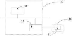
请参阅图8,图8是本申请视觉焊接系统的一实施方式的结构示意图。Please refer to FIG. 8 , which is a schematic structural diagram of an embodiment of the visual welding system of the present application.
本实施例中,视觉焊接系统包括:视觉检测系统10以及激光投射装置20。In this embodiment, the visual welding system includes: a
其中,视觉检测系统10用于对焊接区域内的两个金属部件进行视觉检测,获得两个金属部件的排布方式后,激光投射装置20对确定为空间异面的两个金属部件投射点状激光图案,视觉检测系统10进一步根据点状激光图案以结构光检测方式确定两个金属部件之间的缝隙信息。Wherein, the
其中,视觉检测系统11具体包括了图像传感器及处理器12,在具体实施例中,首先图像传感器11对焊接区域进行图像采集,从而获得视觉检测图像,然后处理器12对图像传感器11所采集到的视觉检测图像进行处理,识别出视觉检测图像中的需要进行缝隙检测的两个金属部件,进一步的,并确定识别出的两个金属部件的具体的排布关系以及位置信息,并将位置与排布信息发送激光投射装置20。The
激光投射装置20主要包括光源,当视觉检测系统10确定了两个金属部件的位置以及具体的排布关系,通过视觉检测系统10发送过来两个金属部件的位置信息以及排布方式来确定激光检测的方式,具体的,及通过处理器12传来的信息,光源21通过所得到的两个金属部件的位置信息以及排布信息来投射不同激光图案。The
可选的,视觉检测系统10传来消息为的两个金属的排布关系为空间异面设置时:Optionally, when the message from the
则激光投射装置20的光源21投射点状激光图案到两个金属部件上,并根据金属部件具体的位置信息,使得分别作用于所述两个金属部件的表面上的所述点状激光图案的数量不少于两个。Then, the
在光源21将预设的激光图案投射到两个金属部件表面后,图像传感器11负责对两个金属部件进行图像采集,从而获取到缝隙检测图像,处理器12通过获取到的缝隙检测图像,从缝隙检测图像中分别出两个金属表面的激光图案,并根据激光图案缝隙图像中的位置信息分别两个金属部件表面的至少两个参考点的空间坐标,在根据各金属部件上的至少两个参考点的空间坐标确定各金属部件对应的空间直线方程,进一步根据各金属部件的空间直线方程计算两个金属部件之间缝隙信息。After the
其具体的检测方式,上述实施例中已经进行过叙述,这里不再赘述。The specific detection method has been described in the above embodiments, and will not be repeated here.
需要知道的,本实施例提供的图像传感器11采用的是成本较低2D图像传感器,其通过与处理器12、光源21进行配合,构成一个光源21、金属部件、图像传感器11的3D结构模型,基于结构光原理,通过对金属部件上的图像进行采集,一方面所取点的平面位置信息得到所取点的横纵轴坐标,一方面根据图像相对光源21、图像传感器11的偏移度来获取到所取点的竖轴坐标。It should be known that the
同时,本实施例提供的处理器12不仅仅限制于图像处理,还可以进行其他的处理,如控制光源20投射的方向,控制图像传感器11的采集角度等,在其他实施例中,处理器12也可以通过外接来实现,为了节省成本,处理器12也可以同时对多个系统进行相关处理。Meanwhile, the
参阅图9,图9为本申请计算机存储介质一实施方式的结构示意图,有能够实现上述所有方法的程序文件31,该程序文件31可以以软件产品的形式存储在上述存储装置中,同时还是记录各种计算的数据,包括若干指令用以使得一台计算机设备(可以是个人计算机,服务器,或者网络设备等)或处理器(processor)执行本申请各个实施方式方法的全部或部分步骤。Referring to FIG. 9, FIG. 9 is a schematic structural diagram of an embodiment of the computer storage medium of the application, and there is a
而前述的存储装置包括:U盘、移动硬盘、只读存储器(ROM,Read-Only Memory)、随机存取存储器(RAM,Random Access Memory)、磁碟或者光盘等各种可以存储程序代码的介质,或者是计算机、服务器、手机、平板等终端设备。The aforementioned storage devices include: U disk, removable hard disk, Read-Only Memory (ROM, Read-Only Memory), Random Access Memory (RAM, Random Access Memory), magnetic disk or optical disk and other media that can store program codes , or terminal devices such as computers, servers, mobile phones, and tablets.
综上,本领域技术人员容易理解,本申请提供一种视觉焊接系统的缝隙检测方法以及系统,通过对焊接区域的两个金属部件的位置视觉检测以及排布方式,选择相应激光检测方式向两个金属部件投射预设形状的激光图案,并根据采集到的激光图案,计算出激光图案的位置关系,进一步计算出两个金属部件之间的缝隙信息,通过上述方法,通过采用2D视觉系统缝隙检测代替了昂贵的3D视觉系统缝隙检测,且对减少了光源的使用,从而优化了缝隙检测方法,提高了工作效率,并且降低了成本。To sum up, those skilled in the art can easily understand that the present application provides a method and system for gap detection of a visual welding system, through visual detection and arrangement of the positions of two metal parts in the welding area, selecting a corresponding laser detection method to the two metal parts. Each metal part projects a laser pattern of a preset shape, and according to the collected laser pattern, the positional relationship of the laser pattern is calculated, and the gap information between the two metal parts is further calculated. Through the above method, by using the 2D vision system gap The detection replaces the expensive 3D vision system gap detection and reduces the use of light sources, thereby optimizing the gap detection method, improving work efficiency and reducing costs.
以上仅为本申请的实施方式,并非因此限制本申请的专利范围,凡是利用本申请说明书及附图内容所作的等效结构或等效流程变换,或直接或间接运用在其他相关的技术领域,均同理包括在本申请的专利保护范围内。The above are only the embodiments of the present application, and are not intended to limit the scope of the patent of the present application. Any equivalent structure or equivalent process transformation made by using the contents of the description and drawings of the present application, or directly or indirectly applied in other related technical fields, All are similarly included in the scope of patent protection of the present application.
Claims (7)
Translated fromChineseApplications Claiming Priority (1)
| Application Number | Priority Date | Filing Date | Title |
|---|---|---|---|
| PCT/CN2018/103077WO2020042032A1 (en) | 2018-08-29 | 2018-08-29 | Method and system for detecting gap of visual welding system |
Publications (2)
| Publication Number | Publication Date |
|---|---|
| CN111630342A CN111630342A (en) | 2020-09-04 |
| CN111630342Btrue CN111630342B (en) | 2022-04-15 |
Family
ID=69644899
Family Applications (1)
| Application Number | Title | Priority Date | Filing Date |
|---|---|---|---|
| CN201880087341.3AActiveCN111630342B (en) | 2018-08-29 | 2018-08-29 | Gap detection method and system for visual welding system |
Country Status (2)
| Country | Link |
|---|---|
| CN (1) | CN111630342B (en) |
| WO (1) | WO2020042032A1 (en) |
Families Citing this family (5)
| Publication number | Priority date | Publication date | Assignee | Title |
|---|---|---|---|---|
| CN113414762B (en)* | 2021-06-09 | 2024-05-03 | 配天机器人技术有限公司 | Method and device for shifting welding path, robot and storage device |
| CN113570654A (en)* | 2021-06-16 | 2021-10-29 | 上海工程技术大学 | Automobile surface gap size detection method based on minimum external rectangle and application thereof |
| EP4286789A4 (en) | 2021-12-29 | 2024-08-14 | Contemporary Amperex Technology Co., Limited | Machine vision detection method, detection apparatus and detection system thereof |
| CN116067280B (en)* | 2022-12-30 | 2023-11-14 | 广东富华机械装备制造有限公司 | Container welding position detection method, device, storage medium and equipment |
| CN116882063A (en)* | 2023-07-24 | 2023-10-13 | 深圳市南方众悦科技有限公司 | Self-adaptive selection analysis method and system for automobile parts |
Citations (12)
| Publication number | Priority date | Publication date | Assignee | Title |
|---|---|---|---|---|
| JPS5928608A (en)* | 1982-08-09 | 1984-02-15 | Matsushita Electric Ind Co Ltd | Detector for weld line |
| WO1990007096A1 (en)* | 1988-12-21 | 1990-06-28 | Gmf Robotics Corporation | Method and system for automatically determining the position and orientation of an object in 3-d space |
| WO1993003579A1 (en)* | 1991-07-26 | 1993-02-18 | Isis Innovation Limited | Three-dimensional vision system |
| JP2000088542A (en)* | 1998-09-09 | 2000-03-31 | Mitsubishi Heavy Ind Ltd | Apparatus and method for inspecting soldering |
| CN1617009A (en)* | 2004-09-20 | 2005-05-18 | 深圳大学 | 3D Digital Imaging Method Based on Spatial Lattice Projection |
| US7429999B2 (en)* | 2004-05-24 | 2008-09-30 | CENTRE DE RECHERCHE INDUSTRIELLE DU QUéBEC | Camera calibrating apparatus and method |
| CN104002021A (en)* | 2014-06-06 | 2014-08-27 | 哈尔滨工业大学 | Device for automatic identification and tracking of multi-layer and multi-run welds |
| CN104408732A (en)* | 2014-12-10 | 2015-03-11 | 东北大学 | Large-view-field depth measuring system and method based on omni-directional structured light |
| CN105203072A (en)* | 2014-06-23 | 2015-12-30 | 联想(北京)有限公司 | Information processing method and electronic equipment |
| CN106382884A (en)* | 2016-08-18 | 2017-02-08 | 广东工业大学 | Point light source welding seam scanning detection method |
| CN106984926A (en)* | 2017-05-03 | 2017-07-28 | 武汉科技大学 | A kind of seam tracking system and welding seam tracking method |
| JP6279060B1 (en)* | 2016-12-02 | 2018-02-14 | ジャパンマリンユナイテッド株式会社 | Laser sensor and measuring method |
Family Cites Families (3)
| Publication number | Priority date | Publication date | Assignee | Title |
|---|---|---|---|---|
| JPH0724575A (en)* | 1993-07-13 | 1995-01-27 | Sekisui Chem Co Ltd | Method for measuring distance of gap |
| CN105571502B (en)* | 2015-12-29 | 2019-08-09 | 上海交通大学 | Measurement Method of Weld Gap in Friction Stir Welding |
| CN107824940A (en)* | 2017-12-07 | 2018-03-23 | 淮安信息职业技术学院 | Welding seam traking system and method based on laser structure light |
- 2018
- 2018-08-29CNCN201880087341.3Apatent/CN111630342B/enactiveActive
- 2018-08-29WOPCT/CN2018/103077patent/WO2020042032A1/ennot_activeCeased
Patent Citations (12)
| Publication number | Priority date | Publication date | Assignee | Title |
|---|---|---|---|---|
| JPS5928608A (en)* | 1982-08-09 | 1984-02-15 | Matsushita Electric Ind Co Ltd | Detector for weld line |
| WO1990007096A1 (en)* | 1988-12-21 | 1990-06-28 | Gmf Robotics Corporation | Method and system for automatically determining the position and orientation of an object in 3-d space |
| WO1993003579A1 (en)* | 1991-07-26 | 1993-02-18 | Isis Innovation Limited | Three-dimensional vision system |
| JP2000088542A (en)* | 1998-09-09 | 2000-03-31 | Mitsubishi Heavy Ind Ltd | Apparatus and method for inspecting soldering |
| US7429999B2 (en)* | 2004-05-24 | 2008-09-30 | CENTRE DE RECHERCHE INDUSTRIELLE DU QUéBEC | Camera calibrating apparatus and method |
| CN1617009A (en)* | 2004-09-20 | 2005-05-18 | 深圳大学 | 3D Digital Imaging Method Based on Spatial Lattice Projection |
| CN104002021A (en)* | 2014-06-06 | 2014-08-27 | 哈尔滨工业大学 | Device for automatic identification and tracking of multi-layer and multi-run welds |
| CN105203072A (en)* | 2014-06-23 | 2015-12-30 | 联想(北京)有限公司 | Information processing method and electronic equipment |
| CN104408732A (en)* | 2014-12-10 | 2015-03-11 | 东北大学 | Large-view-field depth measuring system and method based on omni-directional structured light |
| CN106382884A (en)* | 2016-08-18 | 2017-02-08 | 广东工业大学 | Point light source welding seam scanning detection method |
| JP6279060B1 (en)* | 2016-12-02 | 2018-02-14 | ジャパンマリンユナイテッド株式会社 | Laser sensor and measuring method |
| CN106984926A (en)* | 2017-05-03 | 2017-07-28 | 武汉科技大学 | A kind of seam tracking system and welding seam tracking method |
Non-Patent Citations (3)
| Title |
|---|
| 3D reconstruction of complex spatial weld seam for autonomous welding by laser structured light scanning;Ke Zhang等;《Journal of Manufacturing Processes》;20190331;第39卷;第200-207页* |
| 基于点阵结构光视觉技术的轴径测量;王睿;《中国优秀硕士学位论文全文数据库(信息科技辑)》;20141015(第10期);正文第51-58页* |
| 多目视觉在壳体空间异面直线检测中的应用;叶剑波等;《中国包装工业》;20150831;第83-85页* |
Also Published As
| Publication number | Publication date |
|---|---|
| CN111630342A (en) | 2020-09-04 |
| WO2020042032A1 (en) | 2020-03-05 |
Similar Documents
| Publication | Publication Date | Title |
|---|---|---|
| CN111630342B (en) | Gap detection method and system for visual welding system | |
| Dinham et al. | Autonomous weld seam identification and localisation using eye-in-hand stereo vision for robotic arc welding | |
| CN101019096B (en) | Apparatus and method for detecting a pointer relative to a touch surface | |
| JP5713159B2 (en) | Three-dimensional position / orientation measurement apparatus, method and program using stereo images | |
| US9607406B2 (en) | Size measurement device and size measurement method | |
| JP6506731B2 (en) | System and method for scoring clutter used for 3D point cloud matching in vision system | |
| US20130106833A1 (en) | Method and apparatus for optical tracking of 3d pose using complex markers | |
| TW201520540A (en) | Inspection apparatus, method, and computer program product for machine vision inspection | |
| JP2015040856A (en) | Three-dimensional scanner | |
| AU2011207109A1 (en) | Optical overhead wire measurement | |
| CN114581368B (en) | Bar welding method and device based on binocular vision | |
| CN114638795A (en) | Multi-structure light measurement unit online measurement method and system | |
| CN110398215A (en) | Image processing apparatus and method, system, article manufacturing method, storage medium | |
| Rodrigues et al. | Robot trajectory planning using OLP and structured light 3D machine vision | |
| CN113034605B (en) | Method, device, electronic device and storage medium for determining location of target object | |
| US20220292717A1 (en) | 3D Object Detection Using Random Forests | |
| CN204944450U (en) | Depth data measuring system | |
| WO2020042030A1 (en) | Gap detection method and system for visual welding system | |
| CN113804195B (en) | Information processing method and equipment and indoor map positioning method and equipment | |
| CN118822995A (en) | Circular weld detection method, device and terminal equipment | |
| EP3786633A1 (en) | Display control system, inspection control system, display control method, and storage medium | |
| CN117906613A (en) | Paver navigation method, paver navigation device, paver navigation equipment, storage medium and paver | |
| JP2015085434A (en) | Robot, image processing method and robot system | |
| CN104677911A (en) | Inspection apparatus and method for machine vision inspection | |
| WO2020042031A1 (en) | Seam inspection method of vision-based welding system, and system |
Legal Events
| Date | Code | Title | Description |
|---|---|---|---|
| PB01 | Publication | ||
| PB01 | Publication | ||
| SE01 | Entry into force of request for substantive examination | ||
| SE01 | Entry into force of request for substantive examination | ||
| GR01 | Patent grant | ||
| GR01 | Patent grant |