CN111629778A - Offset lead connectors for operating room cable assemblies and methods of making and using the same - Google Patents
Offset lead connectors for operating room cable assemblies and methods of making and using the sameDownload PDFInfo
- Publication number
- CN111629778A CN111629778ACN201880060074.0ACN201880060074ACN111629778ACN 111629778 ACN111629778 ACN 111629778ACN 201880060074 ACN201880060074 ACN 201880060074ACN 111629778 ACN111629778 ACN 111629778A
- Authority
- CN
- China
- Prior art keywords
- lead
- operating room
- room cable
- housing
- connector
- Prior art date
- Legal status (The legal status is an assumption and is not a legal conclusion. Google has not performed a legal analysis and makes no representation as to the accuracy of the status listed.)
- Granted
Links
Images


Classifications
- A—HUMAN NECESSITIES
- A61—MEDICAL OR VETERINARY SCIENCE; HYGIENE
- A61N—ELECTROTHERAPY; MAGNETOTHERAPY; RADIATION THERAPY; ULTRASOUND THERAPY
- A61N1/00—Electrotherapy; Circuits therefor
- A61N1/18—Applying electric currents by contact electrodes
- A61N1/32—Applying electric currents by contact electrodes alternating or intermittent currents
- A61N1/36—Applying electric currents by contact electrodes alternating or intermittent currents for stimulation
- A61N1/372—Arrangements in connection with the implantation of stimulators
- A61N1/375—Constructional arrangements, e.g. casings
- A61N1/3752—Details of casing-lead connections
- A—HUMAN NECESSITIES
- A61—MEDICAL OR VETERINARY SCIENCE; HYGIENE
- A61N—ELECTROTHERAPY; MAGNETOTHERAPY; RADIATION THERAPY; ULTRASOUND THERAPY
- A61N1/00—Electrotherapy; Circuits therefor
- A61N1/02—Details
- A61N1/04—Electrodes
- A61N1/05—Electrodes for implantation or insertion into the body, e.g. heart electrode
- A61N1/0502—Skin piercing electrodes
- A—HUMAN NECESSITIES
- A61—MEDICAL OR VETERINARY SCIENCE; HYGIENE
- A61N—ELECTROTHERAPY; MAGNETOTHERAPY; RADIATION THERAPY; ULTRASOUND THERAPY
- A61N1/00—Electrotherapy; Circuits therefor
- A61N1/18—Applying electric currents by contact electrodes
- A61N1/32—Applying electric currents by contact electrodes alternating or intermittent currents
- A61N1/36—Applying electric currents by contact electrodes alternating or intermittent currents for stimulation
- A61N1/36014—External stimulators, e.g. with patch electrodes
- A61N1/36017—External stimulators, e.g. with patch electrodes with leads or electrodes penetrating the skin
- A—HUMAN NECESSITIES
- A61—MEDICAL OR VETERINARY SCIENCE; HYGIENE
- A61N—ELECTROTHERAPY; MAGNETOTHERAPY; RADIATION THERAPY; ULTRASOUND THERAPY
- A61N1/00—Electrotherapy; Circuits therefor
- A61N1/18—Applying electric currents by contact electrodes
- A61N1/32—Applying electric currents by contact electrodes alternating or intermittent currents
- A61N1/36—Applying electric currents by contact electrodes alternating or intermittent currents for stimulation
- A61N1/372—Arrangements in connection with the implantation of stimulators
- A61N1/37211—Means for communicating with stimulators
- A61N1/37235—Aspects of the external programmer
- A61N1/37241—Aspects of the external programmer providing test stimulations
Landscapes
- Health & Medical Sciences (AREA)
- Life Sciences & Earth Sciences (AREA)
- Animal Behavior & Ethology (AREA)
- Nuclear Medicine, Radiotherapy & Molecular Imaging (AREA)
- Radiology & Medical Imaging (AREA)
- Biomedical Technology (AREA)
- Engineering & Computer Science (AREA)
- General Health & Medical Sciences (AREA)
- Public Health (AREA)
- Veterinary Medicine (AREA)
- Heart & Thoracic Surgery (AREA)
- Cardiology (AREA)
- Biophysics (AREA)
- Electrotherapy Devices (AREA)
Abstract
Description
Translated fromChinese相关申请的交叉引用CROSS-REFERENCE TO RELATED APPLICATIONS
本申请要求于2017年9月15日提交的美国临时专利申请序列号62/559,195的在35U.S.C.§119(e)下的权益,其通过引用并入本文。This application claims the benefit of US Provisional Patent Application Serial No. 62/559,195, filed September 15, 2017, under 35 U.S.C. §119(e), which is incorporated herein by reference.
技术领域technical field
本发明涉及可植入电刺激系统和制造和使用所述系统的方法的领域。本发明还涉及用于与可植入电刺激系统一起使用的手术室线缆组件的偏置引线连接器,以及制造和使用所述手术室线缆组件的方法。The present invention relates to the field of implantable electrical stimulation systems and methods of making and using the same. The present invention also relates to bias lead connectors for operating room cable assemblies for use with implantable electrical stimulation systems, and methods of making and using the same.
背景技术Background technique
可植入电刺激系统已被证明在多种疾病和病症中具有治疗性。例如,脊髓刺激系统已被用作治疗慢性疼痛综合征的治疗形式。外周神经刺激已经被用于治疗慢性疼痛综合征和失禁,具有许多在调查研究中的其他应用。功能性电刺激系统已被应用来为脊髓损伤患者中的瘫痪的四肢(extremities)恢复一些功能。大脑的刺激,例如深部脑刺激,可用于治疗各种疾病或病症。Implantable electrical stimulation systems have been shown to be therapeutic in a variety of diseases and conditions. For example, spinal cord stimulation systems have been used as a form of therapy for chronic pain syndromes. Peripheral nerve stimulation has been used to treat chronic pain syndromes and incontinence, with many other applications under investigation. Functional electrical stimulation systems have been applied to restore some function to paralyzed extremities in spinal cord injury patients. Brain stimulation, such as deep brain stimulation, can be used to treat various diseases or conditions.
刺激器已被开发以提供用于多种治疗的治疗。刺激器可以包括控制模块(具有脉冲发生器)、一个或多个引线,以及每个引线上的刺激器电极的阵列。刺激器电极与待刺激的神经、肌肉或其他组织接触或接近。控制模块中的脉冲发生器产生由电极递送到身体组织的电脉冲。Stimulators have been developed to provide therapy for a variety of treatments. The stimulator may include a control module (with a pulse generator), one or more leads, and an array of stimulator electrodes on each lead. The stimulator electrodes are in contact with or in proximity to the nerve, muscle or other tissue to be stimulated. A pulse generator in the control module generates electrical pulses that are delivered by the electrodes to body tissue.
发明内容SUMMARY OF THE INVENTION
一个实施例是一种用于电刺激系统的手术室线缆组件(operating room cableassembly),该电刺激系统包括引线连接器:具有壳体、从壳体中的第一开口向内延伸并且被配置和布置成容纳引线或引线延伸部的一部分的引线腔,以及布置在壳体内并且被配置和布置成相对于壳体移动的触头组件。触头组件被配置和布置成移动到负载位置并且被偏置以返回到锁定位置。触头组件包括触头,触头被配置和布置成当触头组件处于锁定位置时接合引线腔内的任何引线或引线延伸部的一部分,并且当触头组件处于负载位置时从在引线腔内的引线或引线延伸部的部分脱离。One embodiment is an operating room cable assembly for an electrical stimulation system including a lead connector having a housing, extending inwardly from a first opening in the housing, and being configured and a lead cavity arranged to receive a lead or a portion of a lead extension, and a contact assembly disposed within the housing and configured and arranged to move relative to the housing. The contact assembly is configured and arranged to move to the load position and to be biased to return to the locked position. The contact assembly includes a contact configured and arranged to engage any lead or a portion of a lead extension within the lead cavity when the contact assembly is in the locked position and from within the lead cavity when the contact assembly is in the load position. part of the lead or lead extension is detached.
在至少一些实施例中,手术室线缆组件还包括耦合到触头组件、设置在外壳内并且相对于外壳可移动的按钮,其中该按钮被配置和布置成当按钮被推动时将触头组件移动到负载位置,并且当按钮被释放时将触头组件返回到锁定位置。在至少一些实施例中,按钮包括滑架,并且触头组件被紧固到滑架。在至少一些实施例中,滑架包括引线接合部分,该引线接合部分被配置和布置成当触头组件处于锁定位置时接合该引线或引线延伸部的部分以促进该引线或引线延伸部的保持。In at least some embodiments, the operating room cable assembly further includes a button coupled to the contact assembly, disposed within the housing and movable relative to the housing, wherein the button is configured and arranged to push the contact assembly when the button is pushed Move to the load position and return the contact assembly to the locked position when the button is released. In at least some embodiments, the button includes a carriage, and the contact assembly is fastened to the carriage. In at least some embodiments, the carriage includes a wire bond portion configured and arranged to engage a portion of the wire or wire extension to facilitate retention of the wire or wire extension when the contact assembly is in the locked position .
在至少一些实施例中,手术室线缆组件还包括细长主体,该细长主体耦合到引线连接器并从引线连接器延伸,并且包括导体,每一个导体耦合到引线连接器的触头组件的至少一个触头。在至少一些实施例中,手术室线缆组件还包括试验刺激器连接器,该试验刺激器连接器耦合到细长主体并且包括耦合到细长主体的导体的至少一个触头。In at least some embodiments, the operating room cable assembly further includes an elongated body coupled to and extending from the lead connector, and including conductors, each conductor coupled to a contact assembly of the lead connector at least one contact. In at least some embodiments, the operating room cable assembly further includes a trial stimulator connector coupled to the elongated body and including at least one contact coupled to the conductor of the elongated body.
在至少一些实施例中,手术室线缆组件还包括至少一个弹簧,该弹簧设置在触头组件和壳体之间并且被配置和布置成将触头组件偏置到锁定位置。在至少一些实施例中,手术室线缆组件还包括设置在壳体内并且限定引线腔的至少一部分的引线腔壳体。在至少一些实施例中,引线腔壳体还限定多个触头开口,该多个触头开口与引线腔相交,并且触头组件的触头可以通过触头开口在负载位置和锁定位置之间移动。In at least some embodiments, the operating room cable assembly further includes at least one spring disposed between the contact assembly and the housing and configured and arranged to bias the contact assembly to the locked position. In at least some embodiments, the operating room cable assembly further includes a lead lumen housing disposed within the housing and defining at least a portion of the lead lumen. In at least some embodiments, the lead cavity housing further defines a plurality of contact openings that intersect the lead cavity and through which the contacts of the contact assembly can pass between the loaded position and the locked position move.
在至少一些实施例中,手术室线缆组件还包括从壳体中的第二开口向内延伸的探针腔,该第二开口与引线腔相对并且与引线腔相交。在至少一些实施例中,手术室线缆组件还包括围绕第一开口设置在壳体上的视觉上不同的标记。在至少一些实施例中,触头为“M”型引脚。在至少一些实施例中,触头组件包括具有附接到基部的触头基部。在至少一些实施例中,按钮包括滑架,并且基部是滑架的一部分。In at least some embodiments, the operating room cable assembly further includes a probe lumen extending inwardly from a second opening in the housing, the second opening being opposite and intersecting the lead lumen. In at least some embodiments, the operating room cable assembly further includes visually distinct indicia disposed on the housing around the first opening. In at least some embodiments, the contacts are "M" shaped pins. In at least some embodiments, the contact assembly includes a base having a contact attached to the base. In at least some embodiments, the button includes a carriage, and the base is part of the carriage.
另一个实施例是试验刺激系统,其包括试验刺激器;以及上述手术室线缆组件中的任一个,并且可耦合(或耦合)到试验刺激器。试验刺激系统可选地包括可耦合到手术室线缆组件的引线连接器的引线。试验刺激系统可选地包括可耦合到手术室线缆组件的引线和引线连接器的引线延伸部。Another embodiment is a trial stimulation system comprising a trial stimulator; and any of the aforementioned operating room cable assemblies, and couplable (or coupled) to the trial stimulator. The trial stimulation system optionally includes leads that can be coupled to lead connectors of the operating room cable assembly. The trial stimulation system optionally includes a lead extension that can be coupled to the lead of the operating room cable assembly and the lead connector.
另一个实施例是一种插入套件,其包括上述手术室线缆组件中的任一个和至少一个电刺激引线,每个电刺激引线具有远端端部部分和近端端部部分,并且包括沿着电刺激引线的远端端部部分设置的电极、沿着电刺激引线的近端端部部分设置的端子,以及将电极耦合到端子的导体,其中电刺激引线的近端端部部分可插入手术室线缆组件的引线连接器中。Another embodiment is an insertion kit comprising any one of the operating room cable assemblies described above and at least one electrical stimulation lead, each electrical stimulation lead having a distal end portion and a proximal end portion, and including Electrodes disposed against the distal end portion of the electrical stimulation lead, terminals disposed along the proximal end portion of the electrical stimulation lead, and conductors coupling the electrodes to the terminals, wherein the proximal end portion of the electrical stimulation lead is insertable In the lead connector of the operating room cable assembly.
又一个实施例是一种用于对患者执行试验刺激的方法。该方法包括提供上述手术室线缆组件中的任一个;将电刺激引线的远端端部部分推进(advancing)到患者体内,其中电刺激引线的近端端部部分从患者向外延伸,其中电刺激引线的远端端部部分被推进到沿着电刺激引线的远端端部部分设置的多个电极接近目标刺激位置所处的位置;在触点组件处于负载位置时,将电刺激引线的近端端部部分放置到手术室线缆组件的引线连接器中;以及允许触头组件返回到锁定位置,以将引线的近端端部部分锁定在引线连接器中。Yet another embodiment is a method for performing a trial stimulus on a patient. The method includes providing any one of the operating room cable assemblies described above; advancing a distal end portion of the electrical stimulation lead into the patient, wherein the proximal end portion of the electrical stimulation lead extends outwardly from the patient, wherein The distal end portion of the electrical stimulation lead is advanced to a position where a plurality of electrodes disposed along the distal end portion of the electrical stimulation lead are proximate to the target stimulation site; when the contact assembly is in the load position, the electrical stimulation lead is inserted placing the proximal end portion of the lead into the lead connector of the operating room cable assembly; and allowing the contact assembly to return to the locked position to lock the proximal end portion of the lead in the lead connector.
又一个实施例是一种用于对患者执行试验刺激的方法。该方法包括提供上述手术室线缆组件中的任一个;将电刺激引线的远端端部部分推进到患者体内,其中电刺激引线的近端端部部分从患者向外延伸,其中电刺激引线的远端端部部分被推进到沿着电刺激引线的远端端部部分设置的多个电极接近目标刺激位置所处的位置;将所述引线耦合到引线延伸部;在所述触头组件处于所述负载位置时,将所述引线延伸部的近端端部部分放置到所述手术室线缆组件的所述引线连接器中;以及允许触头组件返回到锁定位置,以将引线延伸部的近端端部部分锁定在引线连接器中。Yet another embodiment is a method for performing a trial stimulus on a patient. The method includes providing any one of the aforementioned operating room cable assemblies; advancing a distal end portion of the electrical stimulation lead into the patient, wherein the proximal end portion of the electrical stimulation lead extends outwardly from the patient, wherein the electrical stimulation lead The distal end portion of the electrical stimulation lead is advanced to a position where a plurality of electrodes disposed along the distal end portion of the electrical stimulation lead is proximate to the target stimulation site; the lead is coupled to the lead extension; the contact assembly is placing the proximal end portion of the lead extension into the lead connector of the operating room cable assembly when in the loaded position; and allowing the contact assembly to return to the locked position to extend the lead The proximal end portion of the portion is locked in the lead connector.
附图说明Description of drawings
参照以下附图描述本发明的非限制性和非穷举性实施例。在附图中,除非另外指明,否则在各个附图中,相同的附图标记指代相同的部件。Non-limiting and non-exhaustive embodiments of the present invention are described with reference to the following figures. In the drawings, the same reference numerals refer to the same parts throughout the various figures unless otherwise indicated.
为了更好地理解本发明,将参考下面的详细描述,其将结合附图进行阅读,其中:For a better understanding of the present invention, reference is made to the following detailed description, which is to be read in conjunction with the accompanying drawings, in which:
图1是根据本发明的电刺激系统的一个实施例的示意图,该电刺激系统包括电耦合到控制模块的桨状引线;1 is a schematic diagram of one embodiment of an electrical stimulation system according to the present invention, the electrical stimulation system including a paddle lead electrically coupled to a control module;
图2是根据本发明的电刺激系统的一个实施例的示意图,该电刺激系统包括电耦合到控制模块的经皮引线;2 is a schematic diagram of one embodiment of an electrical stimulation system according to the present invention, the electrical stimulation system including a percutaneous lead electrically coupled to a control module;
图3A是根据本发明的图1的控制模块的一个实施例的示意图,该控制模块被配置和布置成电耦合至细长装置。3A is a schematic diagram of one embodiment of the control module of FIG. 1 configured and arranged to be electrically coupled to an elongated device in accordance with the present invention.
图3B是根据本发明的引线延伸部的一个实施例的示意图,该引线延伸部被配置和布置成将图2的细长装置电耦合到图1的控制模块;3B is a schematic diagram of one embodiment of a lead extension configured and arranged to electrically couple the elongated device of FIG. 2 to the control module of FIG. 1 in accordance with the present invention;
图4是根据本发明的试验刺激系统的一个实施例的部件的示意图;Figure 4 is a schematic diagram of the components of one embodiment of a trial stimulation system according to the present invention;
图5A是根据本发明的手术室线缆组件的一个实施例的示意性透视图;5A is a schematic perspective view of one embodiment of an operating room cable assembly in accordance with the present invention;
图5B是根据本发明的图5A的手术室线缆组件的引线连接器的示意性透视图;5B is a schematic perspective view of a lead connector of the operating room cable assembly of FIG. 5A in accordance with the present invention;
图5C是根据本发明的图5A的手术室线缆组件的引线连接器的示意性侧视图;5C is a schematic side view of the lead connector of the operating room cable assembly of FIG. 5A in accordance with the present invention;
图6A是根据本发明的图5A的手术室线缆组件的引线连接器的示意性分解图;6A is a schematic exploded view of a lead connector of the operating room cable assembly of FIG. 5A in accordance with the present invention;
图6B是根据本发明的图5A的手术室线缆组件的引线连接器的示意性横截面;6B is a schematic cross-section of a lead connector of the operating room cable assembly of FIG. 5A in accordance with the present invention;
图6C是根据本发明的图5A的手术室线缆组件的引线连接器的按钮、滑架和触头组件的部分的示意性剖视图;以及6C is a schematic cross-sectional view of a portion of a button, carriage, and contact assembly of the lead connector of the operating room cable assembly of FIG. 5A in accordance with the present invention; and
图7是根据本发明的包括设置在控制模块内的电子子组件的刺激系统的部件的一个实施例的示意图。7 is a schematic diagram of one embodiment of the components of a stimulation system including electronic subassemblies disposed within a control module according to the present invention.
具体实施方式Detailed ways
本发明涉及可植入电刺激系统和制造和使用所述系统的方法的领域。本发明还涉及用于与可植入电刺激系统一起使用的手术室线缆组件的按钮引线连接器,以及制造和使用所述手术室线缆组件的方法。The present invention relates to the field of implantable electrical stimulation systems and methods of making and using the same. The present invention also relates to button lead connectors for operating room cable assemblies for use with implantable electrical stimulation systems, and methods of making and using the operating room cable assemblies.
合适的可植入电刺激系统包括但不限于:至少一个引线,其具有沿着引线的远端端部设置的一个或多个电极以及沿着引线的一个或多个近侧端部设置的一个或多个端子。引线包括例如经皮引线、桨状引线和套箍引线。具有引线的电刺激系统的实例可见于例如美国专利号6,181,969;6516227;6,609,029;6,609,032;6,741,892;7,949,395;7,244,150;7,672,734;7,761,165;7,974,706;8,175,710;8,224,450;和8,364,278;以及美国专利申请公开号2007/0150036,其全部通过引用并入本文。Suitable implantable electrical stimulation systems include, but are not limited to, at least one lead having one or more electrodes disposed along the distal end of the lead and one or more electrodes disposed along one or more proximal ends of the lead. or multiple terminals. Leads include, for example, percutaneous leads, paddle leads, and ferrule leads.具有引线的电刺激系统的实例可见于例如美国专利号6,181,969;6516227;6,609,029;6,609,032;6,741,892;7,949,395;7,244,150;7,672,734;7,761,165;7,974,706;8,175,710;8,224,450;和8,364,278;以及美国专利申请公开号2007/0150036 , which are incorporated herein by reference in their entirety.
图1示意性地示出了电刺激系统100的一个实施例。电刺激系统包括控制模块(例如,刺激器或脉冲发生器)102和可耦合到控制模块102的引线103。引线103包括桨状主体104和一个或多个引线主体106。在图1中,引线103示出为具有两个引线主体106。应当理解,引线103可以包括任何合适数量的引线主体,包括例如一个、两个、三个、四个、五个、六个、七个、八个或更多个引线主体106。诸如电极134的电极的阵列133设置在桨状主体104上,并且端子阵列(例如,图3A-3B中的310)沿着一个或多个引线主体106中的每一个设置。FIG. 1 schematically illustrates one embodiment of an
应当理解,电刺激系统可以包括更多、更少或不同的部件,并且可以具有各种不同的配置,包括本文引用的电刺激系统参考中公开的那些配置。例如,代替桨状主体,电极可以设置在形成经皮引线的引线主体的远端处或附近的阵列中。It should be understood that an electrical stimulation system may include more, fewer, or different components, and may have a variety of different configurations, including those disclosed in the electrical stimulation system references cited herein. For example, instead of a paddle body, electrodes may be provided in an array at or near the distal end of the lead body forming the percutaneous lead.
图2示意性地示出了电刺激系统100的另一个实施例,其中引线103是经皮引线。在图2中,示出了沿一个或多个引线主体106设置的电极134。在至少一些实施例中,引线103沿着引线主体106的纵向长度是等直径的。FIG. 2 schematically illustrates another embodiment of an
引线103可以以任何合适的方式耦合到控制模块102。在图1中,引线103被示出为直接耦合到控制模块102。在至少一些其他实施例中,引线103经由一个或多个中间装置(图3B中的324)耦合到控制模块102。例如,在至少一些实施例中,一个或多个引线延伸部324(见例如图3B)可以设置在引线103和控制模块102之间,以延长引线103和控制模块102之间的距离。除了一个或多个引线延伸部之外或代替一个或多个引线延伸部,可以使用其他中间装置,包括例如分路器、适配器等或其组合。应当理解,在电刺激系统100包括设置在引线103和控制模块102之间的多个细长装置的情况下,中间装置可以被配置成任何合适的布置。
在图2中,电刺激系统100被示出为具有被配置和布置成便于将引线103耦合到控制模块102的分路器107。该分路器107包括被配置为耦合到引线103的近端端部的分路器连接器108,以及一个或多个被配置和布置成耦合到控制模块102(或另一分流器、引线延伸部、适配器等)分路器尾部109A和109B。In FIG. 2 , the
参照图1和图2,控制模块102通常包括连接器壳体112和密封的电子壳体114。电子子组件110和可选的电源120设置在电子壳体114中。控制模块连接器144设置在连接器壳体112中。控制模块连接器144被配置和布置为在控制模块102的引线103和电子子组件110之间形成电连接。Referring to FIGS. 1 and 2 , the
电刺激系统或电刺激系统的部件(包括桨状主体104、一个或多个导线主体106和控制模块102)通常被植入患者体内。电刺激系统可用于多种应用,包括但不限于深部脑刺激、神经刺激、脊髓刺激、肌肉刺激等。The electrical stimulation system or components of the electrical stimulation system, including the
电极134可使用任何导电的生物相容性材料形成。合适的材料的实例包括金属、合金、导电聚合物、导电碳等及其组合。在至少一些实施例中,电极134中的一个或多个由铂、铂铱、钯、钯铑或钛中的一个或多个形成。
任何合适数量的电极134可以设置在引线上,包括例如4个、5个、6个、7个、8个、9个、10个、11个、12个、14个、16个、24个、32个或更多个电极134。在桨状引线的情况下,电极134可以以任何合适的布置设置在桨状主体104上。在图1中,电极134被布置成两列,其中每列具有八个电极134。Any suitable number of
桨状主体104(或一个或多个引线主体106)的电极通常设置在非导电的生物相容性材料(例如,硅树脂、聚氨酯、聚醚醚酮(“PEEK”)、环氧树脂等或其组合)中或由其分离。一个或多个引线主体106和(如果适用的话)桨状主体104可以通过包括例如模制(包括注射模制)、铸造等的任何工艺形成期望的形状。非导电材料通常从一个或多个引线主体106的远端端部延伸到一个或多个引线主体106中的每一个的近端端部。The electrodes of the paddle body 104 (or one or more lead bodies 106) are typically disposed in a non-conductive biocompatible material (eg, silicone, polyurethane, polyetheretherketone ("PEEK"), epoxy, etc. or combination thereof) or isolated therefrom. The one or more
在桨状引线的情况下,非导电材料通常从桨状主体104延伸到一个或一个以上引线主体106中的每一个的近端端部。另外,桨状主体104和一个或多个引线主体106的非导电、生物相容性材料可以相同或不同。此外,桨状主体104和一个或多个引线主体106可以是整体结构,或者可以形成永久地或可拆卸地耦合在一起的两个单独的结构。In the case of a paddle lead, the non-conductive material typically extends from the
端子(例如,图3A-3B中的310)通常沿着电刺激系统100的一个或多个引线主体106(以及任何分路器、引线延伸部、适配器等)的近端端部设置,以用于电连接到对应的连接器触头(例如,图3A中的314)。连接器触头布置在连接器(例如,图1-3B中的144;以及图3B中的322)中,其继而设置在例如控制模块102(或引线延伸部、分路器、适配器等)上。导电线、线缆等(未示出)从端子延伸到电极134。通常,一个或多个电极134电耦合到每个端子。在至少一些实施例中,每个端子仅连接到一个电极134。Terminals (eg, 310 in FIGS. 3A-3B ) are typically provided along the proximal end of one or more lead bodies 106 (and any shunts, lead extensions, adapters, etc.) of
导电线(“导体”)可以嵌入在引线主体106的非导电材料中,或者可以设置在沿着引线主体106延伸的一个或多个腔(未示出)中。在一些实施例中,每个导体有单独的腔。在其他实施例中,两个或更多个导体延伸穿过腔。还可以有一个或多个腔(未示出),其在一个或多个引线主体106的近端端部处或附近打开,例如,用于插入探针以便于将一个或多个引线主体106放置在患者体内。另外,可以有一个或多个腔(未示出),其在一个或多个引线主体106的远端端部处或附近打开,例如,用于将药品或药物(drugs and medication)注入到一个或多个引线主体106的植入部位中。在至少一个实施例中,一个或多个腔连续地或定期地用盐水、硬膜外流体等冲洗。在至少一些实施例中,一个或多个腔在远端端部处永久性地或可移除地密封。Conductive wires ("conductors") may be embedded in the non-conductive material of
图3A是被配置和布置用于耦合到控制模块连接器144的一个实施例的一个或多个细长装置300的近端端部的一个实施例的示意性侧视图。一个或多个细长装置可包括例如图1的一个或多个引线主体106、一个或多个中间装置(例如,分流器、图3B的引线延伸部324、适配器等或其组合)或其组合。FIG. 3A is a schematic side view of one embodiment of a proximal end of one or more
控制模块连接器144限定至少一个端口,细长装置300的近端端部可插入到该端口中,如方向箭头312a和312b所示。在图3A(以及其他图中)中,连接器壳体112被示出为具有两个端口304a和30b。连接器壳体112可以限定任何合适数量的端口,包括例如一个、两个、三个、四个、五个、六个、七个、八个或更多个端口。The
控制模块连接器144还包括设置在每个端口304a和304b内的多个连接器触头,例如连接器触头314。当细长装置300插入到端口304a和304b中时,连接器触头314可与沿一个或多个细长装置300的一个或多个近端端部设置的多个端子310对准,以将控制模块102电耦合到设置在引线103的桨状主体104上的电极(图1的134)。在例如美国专利号7,244,150和8,224,450中找到了控制模块中的连接器的示例,其通过引用并入本文。The
图3B是电刺激系统100的另一个实施例的示意性侧视图。电刺激系统100包括引线延伸部324,其被配置和布置成将一个或多个细长装置300(例如,图1和2的引线主体106中的一个、图2的分流器107、适配器、另一个引线延伸部等或其组合)耦合到控制模块102。在图3B中,引线延伸部324被示出为耦合到限定在控制模块连接器144中的单个端口304。另外,引线延伸部324被示出为配置和布置成耦合到单个细长装置300。在替代实施例中,引线延伸部324被配置和布置成耦合到限定在控制模块连接器144中的多个端口304,或者接收多个细长装置300或两者。FIG. 3B is a schematic side view of another embodiment of the
引线延伸部连接器322设置在引线延伸部324上。在图3B中,引线延伸部连接器322被示出为设置在引线延伸部324的远端端部326处。引线延伸部连接器322包括连接器壳体328。连接器壳体328限定至少一个端口330,细长装置300的端子310可以插入到该端口中,如方向箭头338所示。连接器壳体328还包括多个连接器触头,例如连接器触头340。当细长装置300插入端口330中时,设置在连接器壳体328中的连接器触头340可与细长装置300的端子310对准,以将引线延伸部324电耦合到沿引线(图1和图2的103)设置的电极(图1和2中的134)。
在至少一些实施例中,引线延伸部324的近端端部被类似地配置和布置为引线103(或其他细长装置300)的近端端部。引线延伸部324可包括将连接器触头340电耦合到引线延伸部324的与远端端部326相对的近端端部348的多个导电线(未示出)。在至少一些实施例中,设置在引线延伸部324中的导电线可电耦合到沿引线延伸部324的近端端部348设置的多个端子(未示出)。在至少一些实施例中,引线延伸部324的近端端部348被配置和布置成用于插入到设置在另一个引线延伸部中的连接器(或另一中间设备)中。在其他实施例中(并且如图3B所示),引线延伸部324的近端端部348被配置和布置用于插入到控制模块连接器144中。In at least some embodiments, the proximal end of
转向图4,在将引线植入患者体内期间,有时期望在植入完成之前测试患者体内的电极的定位或功能性。测试电极定位或功能的一种方式是将包括电极的引线的远端端部(以及,可选的,一个或多个引线延伸部)植入患者体内。然后引线的近端端部部分(或引线延伸部)可电耦合到试验刺激器,该试验刺激器设置在患者体外以使用电极执行试验刺激。一旦确定电极被正确地定位并且在期望的参数内发挥作用,则试验刺激器可以与引线(或引线延伸部)的近端端部部分解耦,并用可植入的控制模块替换,并且可以完成植入。Turning to Figure 4, during implantation of a lead in a patient, it is sometimes desirable to test the positioning or functionality of the electrodes in the patient before implantation is complete. One way to test electrode positioning or function is to implant the distal end of a lead (and, optionally, one or more lead extensions) that includes the electrode into a patient. The proximal end portion of the lead (or lead extension) can then be electrically coupled to a trial stimulator positioned outside the patient's body to perform trial stimulation using the electrodes. Once it is determined that the electrodes are properly positioned and functioning within the desired parameters, the trial stimulator can be decoupled from the proximal end portion of the lead (or lead extension) and replaced with an implantable control module, and the completion of implant.
在一些实施例中,试验刺激可持续两个、四个、六个、八个、十二个或更多小时或一个、两个、三个、四个、五个或更多天。在这些情况下,患者可以在医院或其他护理设施中。在一些实施例中,试验刺激可以持续一个延长的时间段(例如,2至10天或更长),其中患者与引线、线缆和试验刺激器一起送回家(sent home),以评估治疗的有效性,以确定永久植入系统是否在治疗医疗状况方面将是有效的。在试验刺激期间,引线可通过将引线(或引线延伸部)的近端端部部分电耦合到手术室线缆(“线缆”)(手术室线缆继而电耦合到试验刺激器)而电耦合到试验刺激器。在一些情况下,当多个引线被植入患者体内时,多个引线(或引线延伸部)可以被耦合到线缆。In some embodiments, the trial stimulation may last for two, four, six, eight, twelve or more hours or one, two, three, four, five or more days. In these cases, the patient may be in a hospital or other care facility. In some embodiments, the trial stimulation may be continued for an extended period of time (eg, 2 to 10 days or more), with the patient sent home with the lead, cable, and trial stimulator to evaluate treatment effectiveness to determine whether a permanently implanted system will be effective in treating a medical condition. During trial stimulation, the lead may be electrically coupled by electrically coupling the proximal end portion of the lead (or lead extension) to an operating room cable ("cable"), which in turn is electrically coupled to the trial stimulator. Coupling to the trial stimulator. In some cases, multiple leads (or lead extensions) may be coupled to the cable when the multiple leads are implanted in the patient.
图4是试验刺激装置400的一个实施例的示意图,该试验刺激装置400包括引线403、试验刺激器448和手术室线缆组件450,其将引线403耦合到试验刺激器448。引线403包括电极阵列434和端子阵列410。当手术室线缆组件450耦合到引线403和试验刺激器448中每一个时,端子410被配置和布置成将电极434耦合到试验刺激器448。4 is a schematic diagram of one embodiment of a
在手术期间,电极434设置在患者的体内,而端子410保持在患者体外,如图4中由示意性表示患者皮肤的线462所示。可选地,试验刺激装置400包括一个或多个附加装置(例如,引线延伸部、手术室线缆延伸部、分路器、适配器等或其任何组合)。例如,试验刺激装置可包括引线延伸部,其可耦合到引线403和手术室线缆组件450以及在引线403与手术室线缆组件450之间。During surgery,
手术室线缆组件450包括细长主体458,该细长主体458具有第一端部454和相对的第二端部456、具有连接器触头的引线连接器452、以及可选地具有端子的可选的试验刺激器连接器460(如果手术室线缆组件是永久布线的,则不需要试用刺激器连接器和端子,或以其他方式永久地附接至试验刺激器)。导体(未示出)从引线连接器的连接器触头延伸到试验刺激器连接器的端子。引线连接器452沿着手术室线缆组件450的第一端部454设置,并且引线连接器内的连接器触头可耦合到引线403(或引线延伸部)的端子434。试验刺激器连接器460沿着手术室线缆组件450的第二端部456设置,并且可耦合到试验刺激器448,或者直接地或经由一个或多个手术室线缆延伸部。任何合适的端子可用于手术室线缆组件中,包括环、C形触头、板触头、弹簧引脚(pogo pin)等。端子的示例可以在例如美国专利号7,539,542和8,849,396;美国专利申请公开号2013/0098678;以及美国专利申请序列号14/330,330中找到,其全部通过引用并入本文。The operating
传统上,手术室线缆组件的引线连接器相对较大、庞大且沉重。在一些情况下,传统的引线连接器可能需要两只手来操作。在一些情况下,外科人员可能不清楚如何将引线加载到引线连接器中或如何将引线“锁定”在引线连接器内。Traditionally, the lead connectors of operating room cable assemblies have been relatively large, bulky, and heavy. In some cases, conventional lead connectors may require two hands to operate. In some cases, it may be unclear to the surgeon how to load the lead into the lead connector or how to "lock" the lead within the lead connector.
在下面的描述中,引线将被提及为与引线连接器连接。然而,将理解的是,可以使用引线延伸部来代替用于耦合到具有耦合的引线的引线连接器的继而耦合到引线延伸部的引线中的任何引线。In the following description, the leads will be referred to as being connected with lead connectors. It will be appreciated, however, that lead extensions may be used in place of any of the leads used to couple to a lead connector with coupled leads, which in turn are coupled to the lead extensions.
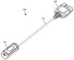
与手术室线缆组件一起使用的引线连接器(或作为引线延伸部上的引线连接器)可包括更简单、更快速且更容易的锁定-解锁机构。在图5A中示出具有细长主体558、引线连接器552和试验刺激器连接器560的手术室线缆组件550的一个实施例。可使用任何合适的试验刺激器连接器560和细长主体558,包括但不限于用于常规或现有手术室线缆组件的那些。例如,细长主体可包括在非导电护层或护套内延伸的多个导体。试验刺激器连接器可以是具有用于连接到试验刺激器的多个触头的任何标准或非标准连接器。替代地,手术室线缆组件560永久地连接到试验刺激器并且不包括试验刺激器连接器。Lead connectors used with operating room cable assemblies (or as lead connectors on lead extensions) may include simpler, faster, and easier locking-unlocking mechanisms. One embodiment of an operating
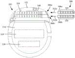
在图5B和5C中的特写视图中示出的引线连接器552包括壳体570和按钮572,按钮572可以朝向引线连接器的中心被推动到用于插入或移除引线(或引线延伸部)的负载位置(参见,图5B、图5C和图6B)。当按钮572被释放时,按钮被偏置以远离引线连接器的中心移动到“锁定位置”,以将引线锁定在引线连接器中。壳体570包括用于插入引线的开口574。可选地,视觉上不同的标记576可以被放置在开口574周围,以促进开口574的视觉识别和引线的插入。例如,标记574可以是与壳体570的周围部分可区分的颜色。包含导体的细长主体558从壳体570延伸并且可包括引导件578以提供稳定性或防止在壳体的出口处的破损,并且可包括应变释放布置。The
图6A示出了引线连接器552的一个实施例的分解图;图6B示出了在负载位置中的该实施例的横截面图;并且图6C示出了引线连接器552的选定部件的一部分(大约一半)的剖视图。除了壳体570和按钮572之外,引线连接器570还包括触头组件580、引线腔壳体582和一个或多个弹簧584。按钮572、壳体570和引线腔壳体582可以由任何合适的材料制成,包括但不限于诸如硅树脂、聚氨酯等或其组合的塑料材料。在至少一些实施例中,按钮572、外壳570和引线腔外壳582仅由非导电材料制成。在一些实施例中,壳体570和引线腔壳体582形成为单件(single piece),并且在其他实施例中,这两个部件是分离的件。6A shows an exploded view of one embodiment of the
触头组件580包括基部590和附接到基部的多个触头592。触头组件580可相对于壳体570移动,并且可移动到用于容纳引线的负载位置。触头组件580被偏置到锁定位置,其中触头组件580接合引线腔内的引线或引线延伸部的一部分,以将引线或引线延伸部的一部分保持或锁定在引线连接器552内。
触头组件580的基部590可以由任何合适的非导电材料制成,例如聚酰亚胺、环氧树脂、其他印刷电路板材料、柔性电路材料、其他塑料等或其组合。触头592由金属或其他导电材料制成,并且当引线(或引线延伸部)的近端部分被正确且完全插入引线连接器570中并且按钮572处于锁定位置时被定位成接合引线(或引线延伸部)的端子。如下面进一步解释的,触头组件580被耦合到按钮572并且与按钮572一起移动以在锁定位置中接合引线(或引线延伸部)或在负载位置中脱离引线(或引线延伸部)。可选地,在锁定位置,触头580可压缩或以其他方式接合引线的端子,以防止引线的近端部分从引线连接器570移除。The
在所示出的实施例中,触头592是“M”形的引脚,但是也可以使用任何其他适当形状的触头。每个触头592被分别电耦合(例如,直接耦合或通过导线耦合)到多个导体594(图6B)中的一个,其从引线连接器552延伸穿过细长主体558(图5A)和延伸到试验刺激器连接器560的对应的触头(图5A)。In the embodiment shown, the
如在图6B中最佳示出的,引线腔壳体582和壳体572限定了引线腔586,该引线腔586从开口574延伸到引线连接器552中并且被布置用于容纳引线(或引线延伸部)的近端部分。可选地,探针开口575和探针腔587也可被限定成使得探针可通过探针开口575和探针腔587插入到引线(或引线延伸部)的近端端部中。引线腔壳体582和壳体572还限定了触头开口596,触头592可以在触头从锁定位置移动到负载位置时穿过触头开口596,反之亦然。As best shown in FIG. 6B,
按钮572包括滑架(carrigae)588,触头组件580附接到该滑架588。可使用任何合适的附接方法,包括但不限于螺钉594、其他紧固件、粘合剂等,并且触头组件580的滑架584和基部590可与例如插入或以其他方式设置在组合布置中的触头一起形成(例如,模制)。在一些实施例中,按钮572和滑架588,而不是如图6B所示的单个整体件,可由通过紧固件、粘合剂等附接在一起的两个或更多个部件制成。
在至少一些实施例中,弹簧584(图6A)位于滑架588和壳体570之间,并且将触头组件580和按钮572推动或偏置到锁定位置。在一些实施例中,壳体570可以包括用于弹簧584的平台或插座。当按钮572被按压到负载位置时,触头组件580移动远离引线腔586。当释放按钮572时,弹簧584将触头组件580和按钮572推进或偏置到锁定位置,其中触头组件580被推向引线腔586。In at least some embodiments, spring 584 (FIG. 6A) is located between
可选地,滑架588包括引线接合部分589,该引线接合部分穿过引线腔壳体582中的开口577以接合或压靠在引线腔586内存在的引线,以便于将引线锁定在引线腔内。图示的实施例具有单个引线接合部分589,但是应当理解,附加的引线接合部分可以被使用并且可以是触头组件580而不是滑架588的一部分。Optionally, the
图7是包括设置在控制模块内的电子子组件710的电刺激系统700的部件的一个实施例的示意图。应当理解,电刺激系统可包括更多、更少或不同的部件,并且可具有各种不同的配置,包括本文引用的刺激器参考文献中公开的那些配置。7 is a schematic diagram of one embodiment of the components of an
如果需要,电刺激系统的一些部件(例如,电源712、天线718、接收器702和处理器704)可以定位在可植入脉冲发生器的密封壳体内的一个或多个电路板或类似载体上。可使用任何电源712,包括例如诸如原电池或可再充电电池的电池。其他电源的实例包括超级电容器、核或原子电池、机械谐振器、红外收集器、热供电能源、弯曲供电能源、生物能电源、燃料电池、生物电电池、渗透压力泵等,包括在美国专利No.7,437,193中描述的电源,在此引入作为参考。If desired, some components of the electrical stimulation system (eg,
作为另一替代方案,可由外部电源经由可选天线718或次级天线通过感应耦合来供应电力。外部电源可以是在安装在用户的皮肤上或以永久或周期性为基础设置在用户附近的单元中的设备中。As another alternative, power may be supplied by inductive coupling from an external power source via
如果需要,如果电源712是可再充电电池,则可以使用可选的天线718对电池进行再充电。可以通过将电池通过天线感应耦合到用户外部的再充电单元716来向电池提供用于再充电的电力。此类布置的示例可在以上所标识的参考文献中找到。If desired, if the
在一个实施例中,电流由桨状或引线主体上的电极134发射,以刺激电刺激系统附近的神经纤维、肌肉纤维或其他身体组织。通常包括处理器704以控制电刺激系统的定时和电特性。例如,如果需要,处理器704可以控制脉冲的定时、频率、强度、持续时间和波形中的一个或多个。另外,如果需要,处理器704可以选择哪个电极可以用于提供刺激。在一些实施例中,处理器704选择是哪个电极是阴极以及哪个电极是阳极。在一些实施例中,处理器704用于识别提供哪个电极对期望组织的最有用的刺激。In one embodiment, electrical current is fired by
任何处理器可以被使用,并且可以像例如以规则间隔产生脉冲的电子设备一样简单,或者该处理器可以能够接收和解释来自允许修改脉冲特性的外部编程单元708的指令。在所说明的实施例中,处理器704耦合到接收器702,继而耦合到可选的天线718。如果需要,这允许处理器704从外部源接收指令,以例如指导脉冲特性和电极的选择。Any processor may be used, and may be as simple as, for example, an electronic device that generates pulses at regular intervals, or the processor may be capable of receiving and interpreting instructions from an
在一个实施例中,天线718能够从由编程单元708编程的外部遥测单元706接收信号(例如,RF信号)。编程单元708可以在遥测单元706的外部,或者是遥测单元706的一部分。如果需要遥测单元706可以是穿戴在用户的皮肤上,或者可以由用户携带的设备,并且可以具有与寻呼机、蜂窝电话或遥控器类似的形式。作为另一个替代方案,遥测单元706可以不由用户穿戴或携带,而是仅可以在家庭站点处或在临床医生的办公室处可用。编程单元708可以是可以向遥测单元706提供信息以传输到电刺激系统700的任何单元。编程单元708可以是遥测单元706的一部分,或者可以经由无线或有线连接向遥测单元706提供信号或信息。合适的编程单元的一个示例是由用户或临床医生操作以向遥测单元706发送信号的计算机。In one embodiment,
经由天线718和接收器702发送到处理器704的信号可以用于修改或以其他方式指导电刺激系统的操作。例如,信号可以用于修改电刺激系统的脉冲,诸如修改脉冲持续时间、脉冲频率、脉冲波形和脉冲强度中的一个或多个。信号还可以指导电刺激系统700停止操作、开始操作、开始对电池充电或停止对电池充电。在其他实施例中,刺激系统不包括天线718或接收器702,并且处理器704按照所编程的操作。Signals sent to
可选地,电刺激系统700可以包括耦合到处理器704和天线718的发射器(未示出),用于将信号发射回到遥测单元706或能够接收信号的另一单元。例如,电刺激系统700可以发送指示电刺激系统700是否正确操作或指示何时需要对电池充电或指示电池中剩余的电荷水平的信号。处理器704还可以能够传输关于脉冲特性的信息,使得用户或临床医生可以确定或验证特性。Optionally,
以上说明书提供了对本发明的制造和使用的描述。因为可以在不脱离本发明的精神和范围的情况下做出本发明的许多实施例,所以本发明也存在于以下所附权利要求中。The above specification provides a description of the manufacture and use of the invention. Since many embodiments of the invention can be made without departing from the spirit and scope of the invention, the invention also resides in the following appended claims.
Claims (15)
Translated fromChineseApplications Claiming Priority (3)
| Application Number | Priority Date | Filing Date | Title |
|---|---|---|---|
| US201762559195P | 2017-09-15 | 2017-09-15 | |
| US62/559,195 | 2017-09-15 | ||
| PCT/US2018/051171WO2019055846A1 (en) | 2017-09-15 | 2018-09-14 | Biased lead connector for operating room cable assembly and methods of making and using |
Publications (2)
| Publication Number | Publication Date |
|---|---|
| CN111629778Atrue CN111629778A (en) | 2020-09-04 |
| CN111629778B CN111629778B (en) | 2024-07-26 |
Family
ID=63963382
Family Applications (1)
| Application Number | Title | Priority Date | Filing Date |
|---|---|---|---|
| CN201880060074.0AActiveCN111629778B (en) | 2017-09-15 | 2018-09-14 | Offset lead connector for operating room cable assemblies and methods of making and using the same |
Country Status (5)
| Country | Link |
|---|---|
| US (2) | US11045656B2 (en) |
| EP (1) | EP3681588B1 (en) |
| CN (1) | CN111629778B (en) |
| AU (1) | AU2018331521B2 (en) |
| WO (1) | WO2019055846A1 (en) |
Families Citing this family (12)
| Publication number | Priority date | Publication date | Assignee | Title |
|---|---|---|---|---|
| US10342983B2 (en) | 2016-01-14 | 2019-07-09 | Boston Scientific Neuromodulation Corporation | Systems and methods for making and using connector contact arrays for electrical stimulation systems |
| US10543374B2 (en) | 2016-09-30 | 2020-01-28 | Boston Scientific Neuromodulation Corporation | Connector assemblies with bending limiters for electrical stimulation systems and methods of making and using same |
| US10905871B2 (en) | 2017-01-27 | 2021-02-02 | Boston Scientific Neuromodulation Corporation | Lead assemblies with arrangements to confirm alignment between terminals and contacts |
| US10814136B2 (en) | 2017-02-28 | 2020-10-27 | Boston Scientific Neuromodulation Corporation | Toolless connector for latching stimulation leads and methods of making and using |
| US10603499B2 (en) | 2017-04-07 | 2020-03-31 | Boston Scientific Neuromodulation Corporation | Tapered implantable lead and connector interface and methods of making and using |
| WO2019023067A1 (en) | 2017-07-25 | 2019-01-31 | Boston Scientific Neuromodulation Corporation | Systems and methods for making and using an enhanced connector of an electrical stimulation system |
| US10639485B2 (en) | 2017-09-15 | 2020-05-05 | Boston Scientific Neuromodulation Corporation | Actuatable lead connector for an operating room cable assembly and methods of making and using |
| US11045656B2 (en) | 2017-09-15 | 2021-06-29 | Boston Scientific Neuromodulation Corporation | Biased lead connector for operating room cable assembly and methods of making and using |
| US11052259B2 (en) | 2018-05-11 | 2021-07-06 | Boston Scientific Neuromodulation Corporation | Connector assembly for an electrical stimulation system and methods of making and using |
| EP3946569B1 (en) | 2019-04-01 | 2023-11-15 | Boston Scientific Neuromodulation Corporation | Low-profile control module for an electrical stimulation system |
| US11357992B2 (en) | 2019-05-03 | 2022-06-14 | Boston Scientific Neuromodulation Corporation | Connector assembly for an electrical stimulation system and methods of making and using |
| US12343547B2 (en) | 2021-08-19 | 2025-07-01 | Boston Scientific Neuromodulation Corporation | Connectors for an electrical stimulation system and methods of making and using |
Citations (5)
| Publication number | Priority date | Publication date | Assignee | Title |
|---|---|---|---|---|
| US5782892A (en)* | 1997-04-25 | 1998-07-21 | Medtronic, Inc. | Medical lead adaptor for external medical device |
| US20130098678A1 (en)* | 2011-10-19 | 2013-04-25 | Boston Scientific Neuromodulation Corporation | Systems and methods for making and using a side-loading operating room cable of an electrical stimulation system |
| CN105451807A (en)* | 2013-08-07 | 2016-03-30 | 波士顿科学神经调制公司 | Systems and methods for making and using lead anchors for leads of electrical stimulation systems |
| WO2016077649A1 (en)* | 2014-11-13 | 2016-05-19 | The Alfred E. Mann Foundation For Scientific Research | Percutaneous lead interface |
| US20160206891A1 (en)* | 2015-01-16 | 2016-07-21 | Boston Scientific Neuromodulation Corporation | Electrical stimulation system with intraoperative cable and methods of making and using |
Family Cites Families (413)
| Publication number | Priority date | Publication date | Assignee | Title |
|---|---|---|---|---|
| US3222471A (en) | 1963-06-10 | 1965-12-07 | Ripley Company Inc | Multiple electrical connector with longitudinal spaced contacts carried by insulating key |
| US3601747A (en) | 1969-09-18 | 1971-08-24 | Singer General Precision | Brush block retractor and alignment device |
| US3771106A (en) | 1971-04-14 | 1973-11-06 | New Nippon Electric Co | Socket suited for revolving the lamp attached thereto |
| US3718142A (en) | 1971-04-23 | 1973-02-27 | Medtronic Inc | Electrically shielded, gas-permeable implantable electro-medical apparatus |
| US3757789A (en) | 1971-10-26 | 1973-09-11 | I Shanker | Electromedical stimulator lead connector |
| US3908668A (en) | 1974-04-26 | 1975-09-30 | Medtronic Inc | Tissue stimulator with sealed lead connector |
| US3951154A (en) | 1974-04-30 | 1976-04-20 | Medtronic, Inc. | Lead connector for electro-medical device |
| US4003616A (en) | 1975-12-03 | 1977-01-18 | Clairol Incorporated | Swivelling electrical connector |
| US3990727A (en) | 1976-01-26 | 1976-11-09 | Stephen Franics Gallagher | Quick detachable coupler |
| US4112953A (en) | 1977-03-11 | 1978-09-12 | Medcor, Inc. | Pacer stimulator with improved lead connector |
| US4180078A (en) | 1978-04-07 | 1979-12-25 | Medtronic, Inc. | Lead connector for a body implantable stimulator |
| US4142532A (en) | 1978-04-07 | 1979-03-06 | Medtronic, Inc. | Body implantable stimulator with novel connector and method |
| USRE31990E (en) | 1978-11-22 | 1985-09-24 | Intermedics, Inc. | Multiple function lead assembly and method for inserting assembly into an implantable tissue stimulator |
| US4245642A (en) | 1979-06-28 | 1981-01-20 | Medtronic, Inc. | Lead connector |
| US4259962A (en) | 1979-08-24 | 1981-04-07 | Cordis Corporation | Sealing system for cardiac pacer lead connector |
| US4310001A (en) | 1980-04-21 | 1982-01-12 | Medtronic, Inc. | Connector assembly for body implantable medical systems |
| US4364625A (en) | 1980-06-12 | 1982-12-21 | Bell Telephone Laboratories, Incorporated | Electrical jack assembly |
| US4367907A (en) | 1980-08-04 | 1983-01-11 | Magnetic Controls Company | Circuit monitoring jack |
| US4630611A (en) | 1981-02-02 | 1986-12-23 | Medtronic, Inc. | Orthogonally-sensing lead |
| US4411276A (en) | 1981-04-28 | 1983-10-25 | Medtronic, Inc. | Implantable multiple connector |
| US4411277A (en) | 1981-04-28 | 1983-10-25 | Medtronic, Inc. | Implantable connector |
| US4461194A (en) | 1982-04-28 | 1984-07-24 | Cardio-Pace Medical, Inc. | Tool for sealing and attaching a lead to a body implantable device |
| US4466441A (en) | 1982-08-02 | 1984-08-21 | Medtronic, Inc. | In-line and bifurcated cardiac pacing lead connector |
| US4516820A (en) | 1983-01-27 | 1985-05-14 | The Commonwealth Of Australia | Cochlear prosthesis package connector |
| US4540236A (en) | 1983-07-18 | 1985-09-10 | Cordis Corporation | Quick lock/quick release connector |
| US4695116A (en) | 1984-02-27 | 1987-09-22 | Switchcraft, Inc. | Stacked electrical jacks |
| US4602624A (en) | 1984-10-11 | 1986-07-29 | Case Western Reserve University | Implantable cuff, method of manufacture, and method of installation |
| US4603696A (en) | 1985-02-14 | 1986-08-05 | Medtronic, Inc. | Lead connector |
| US4614395A (en) | 1985-04-04 | 1986-09-30 | Cordis Corporation | Quick connector to medical electrical lead |
| US4695117A (en) | 1985-06-03 | 1987-09-22 | Switchcraft, Inc. | Jack module and jackfield |
| US4832032A (en) | 1985-08-16 | 1989-05-23 | La Jolla Technology, Inc. | Electrical apparatus protective interconnect |
| JPH0232241Y2 (en) | 1985-10-02 | 1990-09-03 | ||
| US4995389A (en) | 1985-12-16 | 1991-02-26 | Telectronics Pacing Systems, Inc. | Multielectrode quick connect cardiac pacing lead connector assembly |
| US4715380A (en) | 1986-04-03 | 1987-12-29 | Telectronics N.V. | Capped pacer neck containing a connector assembly |
| US4860750A (en) | 1986-04-17 | 1989-08-29 | Intermedics Inc. | Sidelock pacer lead connector |
| US4712557A (en) | 1986-04-28 | 1987-12-15 | Cordis Leads, Inc. | A pacer including a multiple connector assembly with removable wedge and method of use |
| GB2199452B (en) | 1986-12-27 | 1991-09-18 | Iizuka Electric Ind Co Ltd | Electric jack |
| US4744370A (en) | 1987-04-27 | 1988-05-17 | Cordis Leads, Inc. | Lead assembly with selectable electrode connection |
| DE3718913A1 (en) | 1987-06-05 | 1988-12-22 | Siemens Ag | CONNECTING ARRANGEMENT |
| US4784141A (en) | 1987-08-04 | 1988-11-15 | Cordis Leads, Inc. | Lead locking mechanism for cardiac pacers |
| US4850359A (en) | 1987-10-16 | 1989-07-25 | Ad-Tech Medical Instrument Corporation | Electrical brain-contact devices |
| US4869255A (en) | 1987-12-04 | 1989-09-26 | Ad-Tech Medical Instrument Corp. | Electrical connection device |
| US5070605A (en) | 1988-04-22 | 1991-12-10 | Medtronic, Inc. | Method for making an in-line pacemaker connector system |
| US4898173A (en) | 1988-04-22 | 1990-02-06 | Medtronic, Inc. | In-line pacemaker connector system |
| US5007435A (en) | 1988-05-25 | 1991-04-16 | Medtronic, Inc. | Connector for multiconductor pacing leads |
| US4942876A (en)* | 1988-08-02 | 1990-07-24 | Telectronics, N.V. | Pacemaker terminal apparatus |
| US5000194A (en) | 1988-08-25 | 1991-03-19 | Cochlear Corporation | Array of bipolar electrodes |
| US4951687A (en) | 1989-01-31 | 1990-08-28 | Medtronic, Inc. | Medical electrical lead connector |
| US5007864A (en) | 1989-11-27 | 1991-04-16 | Siemens-Pacesetter, Inc. | Device for adapting a pacemaker lead to a pacemaker |
| US5000177A (en) | 1990-01-29 | 1991-03-19 | Cardiac Pacemakers, Inc. | Bipolar lead adapter with resilient housing and rigid retainers for plug seals |
| US5086773A (en) | 1990-09-10 | 1992-02-11 | Cardiac Pacemakers, Inc. | Tool-less pacemaker lead assembly |
| US5069209A (en)* | 1990-09-21 | 1991-12-03 | Telectronics Pacing Systems, Inc. | Electrical terminal |
| US5135001A (en) | 1990-12-05 | 1992-08-04 | C. R. Bard, Inc. | Ultrasound sheath for medical diagnostic instruments |
| US5082453A (en) | 1991-05-16 | 1992-01-21 | Siemens-Pacesetter, Inc. | Multi-contact connector system for an implantable medical device |
| JPH0511600A (en) | 1991-07-06 | 1993-01-22 | Fujitsu Ltd | Electrostatic recording device using one-component developer |
| US5201865A (en) | 1991-10-28 | 1993-04-13 | Medtronic, Inc. | Medical lead impedance measurement system |
| US5241957A (en) | 1991-11-18 | 1993-09-07 | Medtronic, Inc. | Bipolar temporary pacing lead and connector and permanent bipolar nerve wire |
| US5312439A (en) | 1991-12-12 | 1994-05-17 | Loeb Gerald E | Implantable device having an electrolytic storage electrode |
| US5193540A (en) | 1991-12-18 | 1993-03-16 | Alfred E. Mann Foundation For Scientific Research | Structure and method of manufacture of an implantable microstimulator |
| US5193539A (en) | 1991-12-18 | 1993-03-16 | Alfred E. Mann Foundation For Scientific Research | Implantable microstimulator |
| US5358514A (en) | 1991-12-18 | 1994-10-25 | Alfred E. Mann Foundation For Scientific Research | Implantable microdevice with self-attaching electrodes |
| US5261395A (en) | 1992-03-02 | 1993-11-16 | Cardiac Pacemaker, Inc. | Tooless pulse generator to lead connection |
| US5324312A (en) | 1992-05-06 | 1994-06-28 | Medtronic, Inc. | Tool-less threaded connector assembly |
| US5330521A (en) | 1992-06-29 | 1994-07-19 | Cohen Donald M | Low resistance implantable electrical leads |
| EP0580928A1 (en) | 1992-07-31 | 1994-02-02 | ARIES S.r.l. | A spinal electrode catheter |
| US5252090A (en)* | 1992-09-30 | 1993-10-12 | Telectronics Pacing Systems, Inc. | Self-locking implantable stimulating lead connector |
| US5374279A (en) | 1992-10-30 | 1994-12-20 | Medtronic, Inc. | Switchable connector block for implantable defibrillator |
| US5354326A (en) | 1993-01-27 | 1994-10-11 | Medtronic, Inc. | Screening cable connector for interface to implanted lead |
| US5383913A (en) | 1993-04-21 | 1995-01-24 | Schiff; Steven M. | Bidirectional lead connector for left or right sided implantation of pacemakers and/or other implantable electrophysiologic devices and a method for using the same |
| US5336246A (en) | 1993-06-23 | 1994-08-09 | Telectronics Pacing Systems, Inc. | Lead connector assembly for medical device and method of assembly |
| US5348481A (en) | 1993-09-29 | 1994-09-20 | Cardiometrics, Inc. | Rotary connector for use with small diameter flexible elongate member having electrical capabilities |
| US5413595A (en) | 1993-10-15 | 1995-05-09 | Pacesetter, Inc. | Lead retention and seal for implantable medical device |
| ZA948393B (en) | 1993-11-01 | 1995-06-26 | Polartechnics Ltd | Method and apparatus for tissue type recognition |
| US5368496A (en) | 1993-12-10 | 1994-11-29 | Tetrad Corporation | Connector assembly having control lever actuation |
| US5489225A (en) | 1993-12-16 | 1996-02-06 | Ventritex, Inc. | Electrical terminal with a collet grip for a defibrillator |
| US5486202A (en) | 1993-12-17 | 1996-01-23 | Intermedics, Inc. | Cardiac stimulator lead connector |
| US5458629A (en) | 1994-02-18 | 1995-10-17 | Medtronic, Inc. | Implantable lead ring electrode and method of making |
| US5435731A (en) | 1994-05-12 | 1995-07-25 | Kang; Steve | Rotatable hidden connector for telephone transmitter |
| US5522874A (en) | 1994-07-28 | 1996-06-04 | Gates; James T. | Medical lead having segmented electrode |
| US5560358A (en) | 1994-09-08 | 1996-10-01 | Radionics, Inc. | Connector design for multi-contact medical electrode |
| US5582180A (en) | 1994-11-04 | 1996-12-10 | Physio-Control Corporation | Combination three-twelve lead electrocardiogram cable |
| US5534019A (en) | 1994-12-09 | 1996-07-09 | Ventritex, Inc. | Cardiac defibrillator with case that can be electrically active or inactive |
| US5509928A (en) | 1995-03-02 | 1996-04-23 | Pacesetter, Inc. | Internally supported self-sealing septum |
| US5626626A (en) | 1995-05-17 | 1997-05-06 | Ventritex, Inc. | Implantable medical apparatus with magnifying header |
| US5545188A (en) | 1995-06-05 | 1996-08-13 | Intermedics, Inc. | Cardiac pacemaker with collet-type lead connector |
| US5545189A (en) | 1995-11-02 | 1996-08-13 | Ventritex, Inc. | Case-activating switch assembly for an implantable cardiac stimulation device |
| US5669790A (en) | 1995-12-07 | 1997-09-23 | Ventritex, Inc. | Lead lumen sealing device |
| US5679026A (en) | 1995-12-21 | 1997-10-21 | Ventritex, Inc. | Header adapter for an implantable cardiac stimulation device |
| US5766042A (en) | 1995-12-28 | 1998-06-16 | Medtronic, Inc. | Tool-less locking and sealing assembly for implantable medical device |
| SE9600311D0 (en) | 1996-01-29 | 1996-01-29 | Pacesetter Ab | fixation device |
| US6051017A (en) | 1996-02-20 | 2000-04-18 | Advanced Bionics Corporation | Implantable microstimulator and systems employing the same |
| DE19609367A1 (en) | 1996-03-04 | 1997-09-11 | Biotronik Mess & Therapieg | Pacemaker |
| EP0929341B1 (en) | 1996-03-07 | 2005-08-24 | Axon Engineering, Inc. | Polymer-metal foil structure for neural stimulating electrodes |
| US5713922A (en) | 1996-04-25 | 1998-02-03 | Medtronic, Inc. | Techniques for adjusting the locus of excitation of neural tissue in the spinal cord or brain |
| US5711316A (en) | 1996-04-30 | 1998-01-27 | Medtronic, Inc. | Method of treating movement disorders by brain infusion |
| US5951595A (en) | 1996-05-13 | 1999-09-14 | Pacesetteer, Inc. | Setscrewless connector assembly for implantable medical devices |
| DE19622669A1 (en) | 1996-06-05 | 1997-12-11 | Implex Gmbh | Implantable unit |
| US5837006A (en) | 1996-09-10 | 1998-11-17 | Medtronic, Inc. | Retraction stop for helical medical lead electrode |
| US5730628A (en) | 1996-09-25 | 1998-03-24 | Pacesetter, Inc. | Multi-contact connector for an implantable medical device |
| US5843148A (en) | 1996-09-27 | 1998-12-01 | Medtronic, Inc. | High resolution brain stimulation lead and method of use |
| US5796044A (en) | 1997-02-10 | 1998-08-18 | Medtronic, Inc. | Coiled wire conductor insulation for biomedical lead |
| US6208894B1 (en) | 1997-02-26 | 2001-03-27 | Alfred E. Mann Foundation For Scientific Research And Advanced Bionics | System of implantable devices for monitoring and/or affecting body parameters |
| US6164284A (en) | 1997-02-26 | 2000-12-26 | Schulman; Joseph H. | System of implantable devices for monitoring and/or affecting body parameters |
| WO1998037926A1 (en) | 1997-02-26 | 1998-09-03 | Alfred E. Mann Foundation For Scientific Research | Battery-powered patient implantable device |
| JP3774237B2 (en) | 1997-03-25 | 2006-05-10 | ラディ・メディカル・システムズ・アクチェボラーグ | Female connector |
| US5800495A (en) | 1997-03-27 | 1998-09-01 | Sulzer Intermedics Inc. | Endocardial lead assembly |
| US5931861A (en) | 1997-04-25 | 1999-08-03 | Medtronic, Inc. | Medical lead adaptor having rotatable locking clip mechanism |
| US5843141A (en) | 1997-04-25 | 1998-12-01 | Medronic, Inc. | Medical lead connector system |
| US6080188A (en) | 1997-06-16 | 2000-06-27 | Medtronic, Inc. | Setscrew less lead connector system for medical devices |
| FR2765486B1 (en) | 1997-07-03 | 1999-10-01 | Ela Medical Sa | SYSTEM FOR THE MECHANICAL IMMOBILIZATION OF A PROBE CONNECTOR IN AN ACTIVE IMPLANTABLE MEDICAL DEVICE GENERATOR CONNECTOR, IN PARTICULAR FOR A HEART STIMULATOR, DEFIBRILLATOR AND / OR CARDIOVERTER |
| US7231253B2 (en) | 1997-08-01 | 2007-06-12 | Medtronic, Inc. | IMD connector header with grommet retainer |
| US5906634A (en) | 1997-08-08 | 1999-05-25 | Cardiac Pacemakers, Inc. | Implantable device having a quick connect mechanism for leads |
| JPH1169782A (en) | 1997-08-11 | 1999-03-09 | Seiko Epson Corp | Power supply circuit, liquid crystal display device and electronic equipment |
| US6125302A (en) | 1997-09-02 | 2000-09-26 | Advanced Bionics Corporation | Precurved modiolar-hugging cochlear electrode |
| US6006135A (en) | 1997-09-26 | 1999-12-21 | Medtronic, Inc. | Apparatus for interconnecting implantable electrical leads and medical device |
| US5938688A (en) | 1997-10-22 | 1999-08-17 | Cornell Research Foundation, Inc. | Deep brain stimulation method |
| US6198969B1 (en) | 1998-02-12 | 2001-03-06 | Advanced Bionics Corporation | Implantable connector for multi-output neurostimulators |
| US5989077A (en) | 1998-03-13 | 1999-11-23 | Intermedics Inc | Connector for implantable medical device |
| US6167314A (en) | 1998-04-14 | 2000-12-26 | Intermedics Inc. | Cardiac pacemaker lead with pacemaker connector |
| US6161047A (en) | 1998-04-30 | 2000-12-12 | Medtronic Inc. | Apparatus and method for expanding a stimulation lead body in situ |
| US6134478A (en) | 1998-06-05 | 2000-10-17 | Intermedics Inc. | Method for making cardiac leads with zone insulated electrodes |
| US6224450B1 (en) | 1998-08-28 | 2001-05-01 | Laurie J. Norton | Cycling activity belt |
| US6181969B1 (en) | 1998-06-26 | 2001-01-30 | Advanced Bionics Corporation | Programmable current output stimulus stage for implantable device |
| US6322559B1 (en) | 1998-07-06 | 2001-11-27 | Vnus Medical Technologies, Inc. | Electrode catheter having coil structure |
| US6018684A (en) | 1998-07-30 | 2000-01-25 | Cardiac Pacemakers, Inc. | Slotted pacing/shocking electrode |
| US6162101A (en) | 1998-09-03 | 2000-12-19 | Pmt Corporation | Connector assembly for electrodes |
| US6112121A (en) | 1998-09-09 | 2000-08-29 | Intermedics Inc. | Implantable medical device with positive indication of lead connection and connector therefor |
| SE9803692D0 (en) | 1998-10-27 | 1998-10-27 | Pacesetter Ab | A connector for a heart stimulator |
| US6321126B1 (en) | 1998-12-07 | 2001-11-20 | Advanced Bionics Corporation | Implantable connector |
| EP1146816B1 (en) | 1998-12-23 | 2005-10-12 | Nuvasive Inc. | Nerve surveillance cannulae systems |
| US6564078B1 (en) | 1998-12-23 | 2003-05-13 | Nuvasive, Inc. | Nerve surveillance cannula systems |
| US6393325B1 (en) | 1999-01-07 | 2002-05-21 | Advanced Bionics Corporation | Directional programming for implantable electrode arrays |
| US6154678A (en) | 1999-03-19 | 2000-11-28 | Advanced Neuromodulation Systems, Inc. | Stimulation lead connector |
| US6216045B1 (en) | 1999-04-26 | 2001-04-10 | Advanced Neuromodulation Systems, Inc. | Implantable lead and method of manufacture |
| US6167311A (en) | 1999-06-14 | 2000-12-26 | Electro Core Techniques, Llc | Method of treating psychological disorders by brain stimulation within the thalamus |
| US6516227B1 (en) | 1999-07-27 | 2003-02-04 | Advanced Bionics Corporation | Rechargeable spinal cord stimulator system |
| US7949395B2 (en) | 1999-10-01 | 2011-05-24 | Boston Scientific Neuromodulation Corporation | Implantable microdevice with extended lead and remote electrode |
| US6391985B1 (en) | 1999-10-21 | 2002-05-21 | Union Carbide Chemicals & Plastics Technology Corporation | High condensing mode polyolefin production under turbulent conditions in a fluidized bed |
| TW468807U (en) | 1999-11-05 | 2001-12-11 | Hon Hai Prec Ind Co Ltd | Fixed stand for the computer host |
| US6605094B1 (en) | 1999-11-19 | 2003-08-12 | Advanced Bionics Corporation | Integrated subcutaneous tunneling and carrying tool |
| US6556873B1 (en) | 1999-11-29 | 2003-04-29 | Medtronic, Inc. | Medical electrical lead having variable bending stiffness |
| US6609029B1 (en) | 2000-02-04 | 2003-08-19 | Advanced Bionics Corporation | Clip lock mechanism for retaining lead |
| IL151099A0 (en) | 2000-02-09 | 2003-04-10 | Transneuronix Inc | Medical implant device for electrostimulation using discrete micro-electrodes |
| US6271094B1 (en) | 2000-02-14 | 2001-08-07 | International Business Machines Corporation | Method of making MOSFET with high dielectric constant gate insulator and minimum overlap capacitance |
| US6370434B1 (en) | 2000-02-28 | 2002-04-09 | Cardiac Pacemakers, Inc. | Cardiac lead and method for lead implantation |
| US6430442B1 (en) | 2000-02-29 | 2002-08-06 | Medtronic, Inc. | Split contact with super elastic retaining ring for implantable medical device |
| US6473654B1 (en) | 2000-03-08 | 2002-10-29 | Advanced Bionics Corporation | Lead anchor |
| SE0000779D0 (en) | 2000-03-08 | 2000-03-08 | Pacesetter Ab | Process in connection with pacers |
| US6741892B1 (en) | 2000-03-10 | 2004-05-25 | Advanced Bionics Corporation | Movable contact locking mechanism for spinal cord stimulator lead connector |
| US6397108B1 (en) | 2000-04-03 | 2002-05-28 | Medtronic Inc. | Safety adaptor for temporary medical leads |
| US6671534B2 (en) | 2000-04-19 | 2003-12-30 | Ad-Tech Medical Instrument Corporation | Electrical connector for multi-contact medical electrodes |
| US6415168B1 (en) | 2000-04-19 | 2002-07-02 | Ad-Tech Medical Instrument Corporation | Electrical connector for multi-contact medical electrodes |
| US6725096B2 (en)* | 2000-05-05 | 2004-04-20 | Advanced Bionics Corporation | Multiple in-line contact connector |
| US6687538B1 (en)* | 2000-06-19 | 2004-02-03 | Medtronic, Inc. | Trial neuro stimulator with lead diagnostics |
| US6295944B1 (en) | 2000-06-20 | 2001-10-02 | J Timothy Lovett | Automatic tethering system for a floating dock |
| US6510347B2 (en) | 2000-08-17 | 2003-01-21 | William N. Borkan | Spinal cord stimulation leads |
| US6805675B1 (en) | 2000-09-12 | 2004-10-19 | Medtronic, Inc. | Method and apparatus for deflecting a screw-in lead |
| US6757970B1 (en) | 2000-11-07 | 2004-07-06 | Advanced Bionics Corporation | Method of making multi-contact electrode array |
| EP1341579B1 (en) | 2000-12-07 | 2006-11-29 | Medtronic, Inc. | Directional brain stimulation and recording leads |
| US6319021B1 (en) | 2000-12-19 | 2001-11-20 | Hon Hai Precision Ind. Co., Ltd. | Power connector providing improved performance |
| US7033326B1 (en) | 2000-12-29 | 2006-04-25 | Advanced Bionics Corporation | Systems and methods of implanting a lead for brain stimulation |
| US6975906B2 (en) | 2001-02-08 | 2005-12-13 | Wilson Greatbatch Ltd. | One piece header assembly over molded to an implantable medical device |
| US6854994B2 (en) | 2001-04-19 | 2005-02-15 | Medtronic, Inc. | Medical electrical lead connector arrangement including anti-rotation means |
| GB0104982D0 (en) | 2001-02-28 | 2001-04-18 | Gill Steven | Electrode |
| US6498952B2 (en) | 2001-03-08 | 2002-12-24 | Pacesetter, Inc. | Hermetically sealed feedthrough connector using shape memory alloy for implantable medical device |
| US6428368B1 (en) | 2001-03-26 | 2002-08-06 | Pacesetter, Inc. | Side actuated lead connector assembly for implantable tissue stimulation device |
| US6921295B2 (en) | 2001-04-19 | 2005-07-26 | Medtronic, Inc. | Medical lead extension and connection system |
| US6466824B1 (en) | 2001-04-23 | 2002-10-15 | Medtronic, Inc. | Bi-atrial and/or bi-ventricular patient safety cable and methods regarding same |
| US6671553B1 (en) | 2001-05-23 | 2003-12-30 | Pacesetter, Inc. | Implantable cardiac lead having terminating connector strain relief and method of manufacture |
| US6968235B2 (en) | 2001-07-17 | 2005-11-22 | Medtronic, Inc. | Enhanced method and apparatus to identify and connect a small diameter lead with a low profile lead connector |
| US6799991B2 (en) | 2001-09-05 | 2004-10-05 | Medtronic, Inc. | Medical lead connector |
| US6662035B2 (en) | 2001-09-13 | 2003-12-09 | Neuropace, Inc. | Implantable lead connector assembly for implantable devices and methods of using it |
| US7128600B2 (en) | 2001-10-22 | 2006-10-31 | Oscor Inc. | Adapter for electrical stimulation leads |
| US7270568B2 (en) | 2001-10-22 | 2007-09-18 | Oscor Inc. | Adapter for electrical stimulation leads |
| US7904161B2 (en) | 2001-10-22 | 2011-03-08 | Oscor Inc. | Lead adaptor having low resistance conductors and/or encapsulated housing |
| US6678564B2 (en) | 2001-12-06 | 2004-01-13 | Advanced Cochlear Systems, Inc. | Bio-implant and method of making the same |
| US8364278B2 (en) | 2002-01-29 | 2013-01-29 | Boston Scientific Neuromodulation Corporation | Lead assembly for implantable microstimulator |
| US7516447B2 (en) | 2002-02-22 | 2009-04-07 | Bea Systems, Inc. | Methods and apparatus for building, customizing and using software abstractions of external entities |
| US6663570B2 (en) | 2002-02-27 | 2003-12-16 | Volcano Therapeutics, Inc. | Connector for interfacing intravascular sensors to a physiology monitor |
| US6895276B2 (en) | 2002-02-28 | 2005-05-17 | Medtronic, Inc. | In-line lead header for an implantable medical device |
| US8000802B2 (en) | 2002-04-22 | 2011-08-16 | Medtronic, Inc. | Implantable lead with coplanar contact coupling |
| US7027852B2 (en) | 2002-05-21 | 2006-04-11 | Pacesetter, Inc. | Lead with distal tip surface electrodes connected in parallel |
| US6757039B2 (en) | 2002-06-17 | 2004-06-29 | Yao-Dong Ma | Paper white cholesteric displays employing reflective elliptical polarizer |
| US7860570B2 (en) | 2002-06-20 | 2010-12-28 | Boston Scientific Neuromodulation Corporation | Implantable microstimulators and methods for unidirectional propagation of action potentials |
| US7203548B2 (en) | 2002-06-20 | 2007-04-10 | Advanced Bionics Corporation | Cavernous nerve stimulation via unidirectional propagation of action potentials |
| US7292890B2 (en) | 2002-06-20 | 2007-11-06 | Advanced Bionics Corporation | Vagus nerve stimulation via unidirectional propagation of action potentials |
| ES2426255T3 (en) | 2002-06-28 | 2013-10-22 | Boston Scientific Neuromodulation Corporation | Microstimulator that has a built-in power source and a two-way telemetry system |
| FR2841689B1 (en) | 2002-07-01 | 2010-12-10 | Dixi Microtechniques | MULTI-CONTACTING CONNECTOR FOR ELECTRODE FOR EXAMPLE FOR MEDICAL USE |
| US7554493B1 (en) | 2002-07-08 | 2009-06-30 | Boston Scientific Neuromodulation Corporation | Folded monopole antenna for implanted medical device |
| US20040064164A1 (en) | 2002-09-30 | 2004-04-01 | Ries Andrew J. | Connector module jumper for quadrapolar leads |
| US7047084B2 (en) | 2002-11-20 | 2006-05-16 | Advanced Neuromodulation Systems, Inc. | Apparatus for directionally stimulating nerve tissue |
| US7539542B1 (en) | 2003-01-09 | 2009-05-26 | Boston Scientific Neuromodulation Corporation | Lead connector, lead adapter, and lead insertion apparatus |
| US6980863B2 (en) | 2003-03-20 | 2005-12-27 | Medtronic, Inc. | Neurological stimulation lead extension |
| US7110827B2 (en) | 2003-04-25 | 2006-09-19 | Medtronic, Inc. | Electrical connectors for medical lead having weld-less wiring connection |
| US8078280B2 (en) | 2003-04-25 | 2011-12-13 | Medtronic, Inc. | Implantable biomedical electrical connectors having integral side and inner walls |
| US7130699B2 (en) | 2003-05-13 | 2006-10-31 | Medtronic, Inc. | Medical lead adaptor assembly |
| US7242987B2 (en) | 2003-06-19 | 2007-07-10 | Medtronic, Inc. | Medical lead adaptor |
| US7769458B2 (en) | 2003-07-31 | 2010-08-03 | Medtronic, Inc. | Small format connector clip of an implantable medical device |
| US7647111B2 (en) | 2003-07-31 | 2010-01-12 | Medtronic, Inc. | Connector assembly for connecting a lead and an implantable medical device |
| US7164951B2 (en) | 2003-07-31 | 2007-01-16 | Medtronic, Inc. | Electrical connector assembly having integrated conductive element and elastomeric seal for coupling medical leads to implantable medical devices |
| US20050038489A1 (en) | 2003-08-14 | 2005-02-17 | Grill Warren M. | Electrode array for use in medical stimulation and methods thereof |
| US8065008B2 (en) | 2003-08-21 | 2011-11-22 | Medtronic, Inc. | Multi-polar electrical medical lead connector system |
| US8019420B2 (en) | 2003-08-21 | 2011-09-13 | Medtronic, Inc. | Medical lead connector systems with adapters |
| US8147486B2 (en) | 2003-09-22 | 2012-04-03 | St. Jude Medical, Atrial Fibrillation Division, Inc. | Medical device with flexible printed circuit |
| US7286882B2 (en) | 2003-10-03 | 2007-10-23 | Medtronic, Inc. | Implantable electrical connector system |
| US7512446B2 (en) | 2003-10-24 | 2009-03-31 | Medtronic, Inc. | Lead fixation tool |
| WO2005053789A2 (en) | 2003-11-25 | 2005-06-16 | Advanced Neuromodulation Systems, Inc. | Directional stimulation lead and orientation system, and improved percutaneous-insertion needle and method of implanting a lead |
| US6878013B1 (en) | 2003-12-02 | 2005-04-12 | Edgar G. Behan | Connector apparatus for a medical device |
| US7155283B2 (en) | 2003-12-11 | 2006-12-26 | Medtronic, Inc. | Connector header grommet for an implantable medical device |
| US7070455B2 (en) | 2004-02-23 | 2006-07-04 | Bal Seal Engineering Co., Inc. | Stackable assembly for direct connection between a pulse generator and a human body |
| US7108549B2 (en) | 2004-03-30 | 2006-09-19 | Medtronic, Inc. | Medical electrical connector |
| US7489971B1 (en) | 2004-06-05 | 2009-02-10 | Advanced Neuromodulation Systems, Inc. | Notched electrode for electrostimulation lead |
| US20060015163A1 (en) | 2004-07-19 | 2006-01-19 | Team Brown Enterprises, Llc | Lead extender for implantable device |
| US20060025841A1 (en) | 2004-07-27 | 2006-02-02 | Mcintyre Cameron | Thalamic stimulation device |
| US7548788B2 (en) | 2004-08-04 | 2009-06-16 | Boston Scientific Neuromodulation Corporation | Operating room lead connector |
| US7191009B2 (en) | 2004-08-09 | 2007-03-13 | Medtronic, Inc. | Means for increasing implantable medical device electrode surface area |
| US20060030204A1 (en) | 2004-08-09 | 2006-02-09 | Advanced Neuromodulation Systems, Inc. | System and method for providing strain relief for medical device leads |
| JP4751393B2 (en) | 2004-08-26 | 2011-08-17 | バル・シール・エンジニアリング・カンパニー・インコーポレーテッド | Conductive pathway for medical electronic devices |
| CN2740095Y (en) | 2004-09-30 | 2005-11-16 | 汪恩光 | Double Blade Vegetable and Fruit Peeler |
| US7283878B2 (en) | 2004-10-12 | 2007-10-16 | Medtronic, Inc. | Lead stabilizer and extension wire |
| US7083474B1 (en) | 2004-12-08 | 2006-08-01 | Pacesetter, Inc. | System for lead retention and sealing of an implantable medical device |
| JP5112879B2 (en) | 2004-12-22 | 2013-01-09 | プロテウス デジタル ヘルス, インコーポレイテッド | Segmented electrodes that are implantable and addressable |
| US20080077186A1 (en) | 2006-04-18 | 2008-03-27 | Proteus Biomedical, Inc. | High phrenic, low capture threshold pacing devices and methods |
| US7809446B2 (en) | 2005-01-05 | 2010-10-05 | Boston Scientific Neuromodulation Corporation | Devices and methods for brain stimulation |
| US7783359B2 (en) | 2005-01-05 | 2010-08-24 | Boston Scientific Neuromodulation Corporation | Devices and methods using an implantable pulse generator for brain stimulation |
| US8019439B2 (en) | 2005-01-11 | 2011-09-13 | Boston Scientific Neuromodulation Corporation | Lead assembly and method of making same |
| US8066702B2 (en) | 2005-01-11 | 2011-11-29 | Rittman Iii William J | Combination electrical stimulating and infusion medical device and method |
| US20060167522A1 (en) | 2005-01-25 | 2006-07-27 | Malinowski Zdzislaw B | Connector for use in an implantable stimulator device |
| US7422487B2 (en) | 2005-01-27 | 2008-09-09 | Oscos Inc. | Electrical connector and devices using the same |
| WO2006083881A1 (en) | 2005-01-31 | 2006-08-10 | Medtronic, Inc. | Method of manufacturing a medical lead |
| US7168165B2 (en) | 2005-03-07 | 2007-01-30 | Medtronic, Inc. | Fabrication of electrical medical leads employing multi-filar wire conductors |
| US20060224208A1 (en) | 2005-04-05 | 2006-10-05 | Bal Seal Engineering Co., Inc. | Medical electronics electrical implantable medical devices |
| US8565898B2 (en) | 2005-04-28 | 2013-10-22 | Medtronic, Inc. | Rate control during AF using cellular intervention to modulate AV node |
| US8594807B2 (en) | 2005-05-02 | 2013-11-26 | Boston Scientific Neuromodulation Corporation | Compliant stimulating electrodes and leads and methods of manufacture and use |
| US7962213B2 (en) | 2005-05-12 | 2011-06-14 | Cardiac Pacemakers, Inc. | Interconnected electrode assembly for a lead connector and method therefor |
| US7316593B2 (en) | 2005-05-19 | 2008-01-08 | Bal Seal Engineering Co., Inc. | Electrical connector with embedded canted coil spring |
| US7822482B2 (en) | 2005-07-29 | 2010-10-26 | Medtronic, Inc. | Electrical stimulation lead with rounded array of electrodes |
| US7761165B1 (en) | 2005-09-29 | 2010-07-20 | Boston Scientific Neuromodulation Corporation | Implantable stimulator with integrated plastic housing/metal contacts and manufacture and use |
| US8271094B1 (en) | 2005-09-30 | 2012-09-18 | Boston Scientific Neuromodulation Corporation | Devices with cannula and electrode lead for brain stimulation and methods of use and manufacture |
| US7590451B2 (en) | 2005-10-31 | 2009-09-15 | Medtronic, Inc. | Axial lead connector for implantable medical devices |
| US7650184B2 (en) | 2005-12-01 | 2010-01-19 | Boston Scientific Neuromodulation Corporation | Cylindrical multi-contact electrode lead for neural stimulation and method of making same |
| US7610103B2 (en) | 2005-12-19 | 2009-10-27 | Boston Scientific Neuromodulation Corporation | Electrode arrangement for nerve stimulation and methods of treating disorders |
| US8700178B2 (en) | 2005-12-27 | 2014-04-15 | Boston Scientific Neuromodulation Corporation | Stimulator leads and methods for lead fabrication |
| US7672734B2 (en) | 2005-12-27 | 2010-03-02 | Boston Scientific Neuromodulation Corporation | Non-linear electrode array |
| US7244150B1 (en) | 2006-01-09 | 2007-07-17 | Advanced Bionics Corporation | Connector and methods of fabrication |
| US7241180B1 (en) | 2006-01-31 | 2007-07-10 | Medtronic, Inc. | Medical electrical lead connector assembly |
| US8380321B2 (en) | 2006-02-24 | 2013-02-19 | Medtronic, Inc. | Programming interface with a cross-sectional view of a stimulation lead with complex electrode array geometry |
| US7848802B2 (en) | 2006-02-24 | 2010-12-07 | Medtronic, Inc. | Programming interface with a concentric axial view of a stimulation lead with complex electrode array geometry |
| US7822483B2 (en) | 2006-02-24 | 2010-10-26 | Medtronic, Inc. | Electrical and activation field models for configuring stimulation therapy |
| WO2007100277A1 (en) | 2006-03-02 | 2007-09-07 | St.Jude Medical Ab | A medical implantable lead and a method for manufacturing of the same |
| US8175710B2 (en) | 2006-03-14 | 2012-05-08 | Boston Scientific Neuromodulation Corporation | Stimulator system with electrode array and the method of making the same |
| ATE474622T1 (en) | 2006-03-23 | 2010-08-15 | Medtronic Inc | SYSTEMS AND METHODS FOR CONNECTING MEDICAL ELECTRODES |
| US7526339B2 (en) | 2006-03-27 | 2009-04-28 | Medtronic, Inc. | IPG connector headers for implantable medical devices |
| US7974706B2 (en) | 2006-03-30 | 2011-07-05 | Boston Scientific Neuromodulation Corporation | Electrode contact configurations for cuff leads |
| US7583999B2 (en) | 2006-07-31 | 2009-09-01 | Cranial Medical Systems, Inc. | Multi-channel connector for brain stimulation system |
| US8321025B2 (en) | 2006-07-31 | 2012-11-27 | Cranial Medical Systems, Inc. | Lead and methods for brain monitoring and modulation |
| ES2699474T3 (en) | 2006-08-07 | 2019-02-11 | Alpha Omega Neuro Tech Ltd | Brain electrodes |
| US8224450B2 (en) | 2006-09-18 | 2012-07-17 | Boston Scientific Neuromodulation Corporation | Feed through interconnect assembly for an implantable stimulation system and methods of making and using |
| JP5475453B2 (en) | 2006-09-26 | 2014-04-16 | サピエンス ステアリング ブレイン スティムレーション ベー ヴィ | Tissue stimulator |
| US20080103580A1 (en) | 2006-10-31 | 2008-05-01 | Medtronic, Inc. | Implantable medical elongated member with dual purpose conduit |
| US7684873B2 (en) | 2006-10-31 | 2010-03-23 | Medtronic, Inc. | Implantable medical lead including a directional electrode and fixation elements along an interior surface |
| WO2008053789A1 (en) | 2006-10-31 | 2008-05-08 | Semiconductor Energy Laboratory Co., Ltd. | Semiconductor device |
| US20080114230A1 (en) | 2006-11-14 | 2008-05-15 | Bruce Addis | Electrode support |
| US7717754B2 (en) | 2006-12-07 | 2010-05-18 | Medtronic, Inc. | Connector assembly with internal seals and manufacturing method |
| US7979140B2 (en) | 2006-12-12 | 2011-07-12 | Alfred E. Mann Foundation For Scientific Research | Segmented electrode |
| WO2008072125A1 (en) | 2006-12-13 | 2008-06-19 | Koninklijke Philips Electronics, N.V. | First time right placement of a dbs lead |
| US8131370B2 (en) | 2007-01-18 | 2012-03-06 | Medtronic, Inc | Methods of manufacturing a hermetic lead connector |
| US7720538B2 (en) | 2007-01-18 | 2010-05-18 | Medtronic, Inc. | Internal hermetic lead connector for implantable device |
| US7711427B2 (en) | 2007-01-18 | 2010-05-04 | Medtronis, Inc. | Internal hermetic lead connector for implantable device |
| US7711428B2 (en) | 2007-01-18 | 2010-05-04 | Medtronic, Inc. | Hermetic lead connector assembly |
| US7758384B2 (en) | 2007-02-26 | 2010-07-20 | Medtronic, Inc. | Implantable bifurcated neurostimulator adapters |
| WO2008107815A1 (en) | 2007-03-02 | 2008-09-12 | Koninklijke Philips Electronics N.V. | Electrode system for deep brain stimulation |
| US8190259B1 (en) | 2007-04-10 | 2012-05-29 | Advanced Neuromodulation Systems, Inc. | Header design for implantable pulse generator |
| US7668601B2 (en) | 2007-04-26 | 2010-02-23 | Medtronic, Inc. | Implantable medical lead with multiple electrode configurations |
| US7690953B2 (en) | 2007-05-03 | 2010-04-06 | Deringer-Ney, Inc. | Stackable electrical connection apparatus |
| US7822477B2 (en) | 2007-08-15 | 2010-10-26 | Bal Seal Engineering, Inc. | Connector assembly for use with medical devices |
| US20090054947A1 (en) | 2007-08-20 | 2009-02-26 | Medtronic, Inc. | Electrode configurations for directional leads |
| WO2009025828A1 (en) | 2007-08-20 | 2009-02-26 | Medtronic, Inc. | Stimulation field management |
| EP2214773A2 (en) | 2007-10-02 | 2010-08-11 | Medtronic, Inc. | Connector assemblies and contacts for implantable medical electrical systems |
| EP2217325A1 (en) | 2007-10-03 | 2010-08-18 | Medtronic, Inc. | Connector assemblies for implantable medical electrical systems |
| US20090287191A1 (en) | 2007-12-18 | 2009-11-19 | Searete Llc, A Limited Liability Corporation Of The State Of Delaware | Circulatory monitoring systems and methods |
| US9192409B2 (en) | 2008-01-23 | 2015-11-24 | Boston Scientific Neuromodulation Corporation | Steerable stylet handle assembly |
| US9220889B2 (en) | 2008-02-11 | 2015-12-29 | Intelect Medical, Inc. | Directional electrode devices with locating features |
| US8019440B2 (en) | 2008-02-12 | 2011-09-13 | Intelect Medical, Inc. | Directional lead assembly |
| WO2009114607A1 (en) | 2008-03-12 | 2009-09-17 | Boston Scientific Neuromodulation Corporation | Low-profile connector for a neurostimulation lead |
| EP2262442B1 (en) | 2008-04-11 | 2015-03-25 | BAL Seal Engineering | Connector cartridge stack for electrical transmission |
| US8046073B1 (en) | 2008-04-16 | 2011-10-25 | Boston Scientifique Neuromodulation Corporation | Lead connector for an implantable electric stimulation system and methods of making and using |
| WO2009131874A2 (en) | 2008-04-21 | 2009-10-29 | Boston Scientific Neuromodulation Corporation | High-resolution connector for a neurostimulation lead |
| US8600518B2 (en) | 2008-04-30 | 2013-12-03 | Boston Scientific Neuromodulation Corporation | Electrodes for stimulation leads and methods of manufacture and use |
| US8140163B1 (en) | 2008-05-23 | 2012-03-20 | Advanced Neuromodulation Systems, Inc. | Implantable pulse generator and method of use |
| US7736191B1 (en) | 2008-05-27 | 2010-06-15 | Jerzy Roman Sochor | Implantable connector with protected contacts |
| US8676320B2 (en) | 2008-06-03 | 2014-03-18 | Medtronic, Inc. | Lead having radially spaced apart contacts to allow for adjustability |
| US8140172B1 (en) | 2008-07-11 | 2012-03-20 | Advanced Neuromodulation Systems, Inc. | Implantable anchor with locking arm |
| US7803021B1 (en) | 2008-07-21 | 2010-09-28 | Boston Scientific Neuromodulation Corporation | Implantable electrical stimulation systems with leaf spring connective contacts and methods of making and using |
| US8688235B1 (en) | 2008-07-22 | 2014-04-01 | Boston Scientific Neuromodulation Corporation | Lead with transition and methods of manufacture and use |
| US8092260B2 (en) | 2008-07-31 | 2012-01-10 | Bal Seal Engineering, Inc. | Device for securing leads into in-line connector devices |
| US8301255B2 (en) | 2008-08-12 | 2012-10-30 | Boston Scientific Neuromodulation Corporation | Retention assemblies for implantable electric stimulation systems and methods of making and using |
| US7941227B2 (en) | 2008-09-03 | 2011-05-10 | Boston Scientific Neuromodulation Corporation | Implantable electric stimulation system and methods of making and using |
| US8548601B2 (en) | 2008-09-15 | 2013-10-01 | Boston Scientific Neuromodulation Corporation | Lead connection system for an implantable electrical stimulation system and methods for making and using the systems |
| US20100076535A1 (en) | 2008-09-25 | 2010-03-25 | Boston Scientific Neuromodulation Corporation | Leads with non-circular-shaped distal ends for brain stimulation systems and methods of making and using |
| US8335551B2 (en) | 2008-09-29 | 2012-12-18 | Chong Il Lee | Method and means for connecting a large number of electrodes to a measuring device |
| US8359107B2 (en) | 2008-10-09 | 2013-01-22 | Boston Scientific Neuromodulation Corporation | Electrode design for leads of implantable electric stimulation systems and methods of making and using |
| JP5667987B2 (en) | 2008-11-12 | 2015-02-12 | エコーレ ポリテクニーク フェデラーレ デ ローザンヌ (イーピーエフエル) | Micromachined nerve stimulation device |
| US7974705B2 (en) | 2008-11-13 | 2011-07-05 | Proteus Biomedical, Inc. | Multiplexed multi-electrode neurostimulation devices |
| AU2010236196B2 (en) | 2009-04-16 | 2015-11-12 | Boston Scientific Neuromodulation Corporation | Deep brain stimulation current steering with split electrodes |
| US20100273355A1 (en) | 2009-04-22 | 2010-10-28 | Tyco Electronics Corporation | Image guide wire connection |
| US8225504B2 (en) | 2009-04-24 | 2012-07-24 | Advanced Neuromodulation Systems, Inc. | Medical leads with segmented electrodes and methods of fabrication thereof |
| US8250755B2 (en) | 2009-04-24 | 2012-08-28 | Advanced Neuromodulation Systems, Inc. | Process for fabricating a medical lead |
| US8046909B2 (en) | 2009-04-24 | 2011-11-01 | Advanced Neuromodulation Systems, Inc. | Method of fabricating stimulation lead |
| US9352147B2 (en) | 2009-04-27 | 2016-05-31 | Boston Scientific Neuromodulation Corporation | Torque lock anchor and methods and devices using the anchor |
| US20100287770A1 (en) | 2009-05-14 | 2010-11-18 | Cochlear Limited | Manufacturing an electrode carrier for an implantable medical device |
| US8527054B2 (en) | 2009-06-30 | 2013-09-03 | Richard B. North | Implantable medical device connector |
| US8887387B2 (en) | 2009-07-07 | 2014-11-18 | Boston Scientific Neuromodulation Corporation | Methods of manufacture of leads with a radially segmented electrode array |
| US8875391B2 (en) | 2009-07-07 | 2014-11-04 | Boston Scientific Neuromodulation Corporation | Methods for making leads with radially-aligned segmented electrodes for electrical stimulation systems |
| US8600507B2 (en) | 2009-07-21 | 2013-12-03 | Boston Scientific Neuromodulation Corporation | Multi-port modular connector for implantable electrical stimulation systems and methods of making and using |
| US20110047795A1 (en) | 2009-09-01 | 2011-03-03 | Kevin Turner | Medical leads with segmented electrodes and methods of fabrication thereof |
| US8167660B2 (en) | 2009-09-04 | 2012-05-01 | Bal Seal Engineering, Inc. | Connector assemblies for use with implantable medical devices |
| US20110077699A1 (en) | 2009-09-30 | 2011-03-31 | John Swanson | Medical leads with segmented electrodes and methods of fabrication thereof |
| US8874232B2 (en) | 2009-11-30 | 2014-10-28 | Boston Scientific Neuromodulation Corporation | Electrode array having concentric split ring electrodes and methods of making the same |
| US8295944B2 (en) | 2009-11-30 | 2012-10-23 | Boston Scientific Neuromodulation Corporation | Electrode array with electrodes having cutout portions and methods of making the same |
| US8391985B2 (en) | 2009-11-30 | 2013-03-05 | Boston Scientific Neuromodulation Corporation | Electrode array having concentric windowed cylinder electrodes and methods of making the same |
| US8788063B2 (en) | 2009-11-30 | 2014-07-22 | Boston Scientific Neuromodulation Corporation | Electrode array having a rail system and methods of manufacturing the same |
| US8751002B2 (en) | 2010-01-28 | 2014-06-10 | Medtronic, Inc. | Lead connector with glass braze |
| US9403022B2 (en) | 2010-01-29 | 2016-08-02 | Medtronic, Inc. | Header assembly for implantable medical device |
| US8571665B2 (en) | 2010-03-23 | 2013-10-29 | Boston Scientific Neuromodulation Corporation | Helical radial spacing of contacts on a cylindrical lead |
| US8100726B2 (en) | 2010-03-26 | 2012-01-24 | Hon Hai Precision Ind. Co., Ltd. | Waterproof audio jack and method of making the same |
| US8954163B2 (en) | 2010-03-31 | 2015-02-10 | Medtronic, Inc. | Medical cable connector for a medical lead providing an electrical receptacle that is movable relative to an outer body |
| CA2794093A1 (en) | 2010-04-02 | 2011-10-06 | Boston Scientific Neuromodulation Corporation | Directional lead assembly |
| US8968331B1 (en) | 2010-04-24 | 2015-03-03 | Jerzy Roman Sochor | Implantable lead and surgical accessories |
| US9855413B2 (en) | 2010-04-29 | 2018-01-02 | Donatelle Plastics, Inc. | Header for implantable pulse generator and method of making same |
| US20110270330A1 (en) | 2010-04-29 | 2011-11-03 | Medtronic, Inc. | Diffusion bonded lead connector |
| US8761887B2 (en) | 2010-04-29 | 2014-06-24 | Donatelle Plastics, Inc. | Header for implantable pulse generator and method of making same |
| EP2582425B1 (en) | 2010-06-18 | 2018-04-04 | Boston Scientific Neuromodulation Corporation | Method of making electrode array having embedded electrodes |
| US9675795B2 (en) | 2010-07-16 | 2017-06-13 | Boston Scientific Neuromodulation Corporation | Systems and methods for radial steering of electrode arrays |
| US8494652B2 (en)* | 2010-08-09 | 2013-07-23 | Advanced Neuromodulation Systems, Inc. | Implantable medical anchor |
| US20120046710A1 (en) | 2010-08-18 | 2012-02-23 | Boston Scientific Neuromodulation Corporation | Methods, systems, and devices for deep brain stimulation using helical movement of the centroid of stimulation |
| CA2806905A1 (en) | 2010-08-31 | 2012-03-08 | Boston Scientific Neuromodulation Corporation | Control module with a connector assembly retainer |
| US8583237B2 (en) | 2010-09-13 | 2013-11-12 | Cranial Medical Systems, Inc. | Devices and methods for tissue modulation and monitoring |
| AU2011305914B2 (en) | 2010-09-21 | 2016-05-12 | Boston Scientific Neuromodulation Corporation | Systems and methods for making and using radially-aligned segmented electrodes for leads of electrical stimulation systems |
| US8897876B2 (en) | 2010-09-22 | 2014-11-25 | Boston Scientific Neuromodulation Corporation | Systems and methods for making and using connectors for electrical stimulation systems |
| CA2822343A1 (en) | 2010-12-23 | 2012-06-28 | Boston Scientific Neuromodulation Corporation | Methods for making leads with segmented electrodes for electrical stimulation systems |
| US8700179B2 (en) | 2011-02-02 | 2014-04-15 | Boston Scientific Neuromodulation Corporation | Leads with spiral of helical segmented electrode arrays and methods of making and using the leads |
| US20120203316A1 (en) | 2011-02-08 | 2012-08-09 | Boston Scientific Neuromodulation Corporation | Leads with segmented electrodes for electrical stimulation of planar regions and methods of making and using |
| JP2014511227A (en) | 2011-02-08 | 2014-05-15 | ボストン サイエンティフィック ニューロモデュレイション コーポレイション | Method of manufacturing a lead having segmented electrodes for an electrical stimulation system |
| US8965515B2 (en) | 2011-02-08 | 2015-02-24 | Boston Scientific Neuromodulation Corporation | Systems and methods for making and using improved lead extension connectors for electrical stimulation systems |
| ES2801326T3 (en) | 2011-02-08 | 2021-01-11 | Boston Scient Neuromodulation Corp | Spirally arranged lead wires with segmented electrodes and lead wire manufacturing and use procedures |
| US8428724B2 (en) | 2011-03-11 | 2013-04-23 | Greatbatch Ltd. | Low insertion force electrical connector for implantable medical devices |
| US8682439B2 (en) | 2011-04-08 | 2014-03-25 | Boston Scientific Neuromodulation Corporation | Systems and methods for making and using improved connectors for electrical stimulation systems |
| US8784143B2 (en) | 2011-04-20 | 2014-07-22 | Cardiac Pacemakers, Inc. | Cantilevered spring contact for an implantable medical device |
| JP6460790B2 (en) | 2011-06-07 | 2019-01-30 | ボストン サイエンティフィック ニューロモデュレイション コーポレイション | Systems and methods for making and using improved leads for electrical stimulation systems |
| US8560084B2 (en) | 2011-08-30 | 2013-10-15 | Greatbatch Ltd. | Lead body with inner and outer co-axial coils |
| US9517333B2 (en)* | 2011-08-31 | 2016-12-13 | Nuvectra Corporation | Lead identification system |
| US9677587B2 (en) | 2011-09-21 | 2017-06-13 | Bal Seal Engineering, Inc. | Multi-latching mechanisms and related methods |
| US9138576B2 (en) | 2011-10-28 | 2015-09-22 | Medtronic, Inc. | Lead end having inner support |
| EP2773420B1 (en) | 2011-11-02 | 2016-10-26 | Boston Scientific Neuromodulation Corporation | Methods for making improved leads for electrical stimulation systems |
| US20130116754A1 (en) | 2011-11-08 | 2013-05-09 | Vivek Sharma | Medical device contact assemblies for use with implantable leads, and associated systems and methods |
| WO2013112905A1 (en) | 2012-01-26 | 2013-08-01 | Boston Scientific Neuromodulation Corporation | Systems and methods for identifying the circumferential positioning of electrodes of leads for electrical stimulation systems |
| US9138586B2 (en) | 2012-01-27 | 2015-09-22 | Greatbatch Ltd. | Contact block using spherical electrical contacts for electrically contacting implantable leads |
| US9199071B2 (en) | 2012-02-16 | 2015-12-01 | Boston Scientific Neuromodulation Corporation | Systems and methods for making and using implantable electrical systems with leads that couple to multiple connector ports |
| WO2013142734A1 (en) | 2012-03-21 | 2013-09-26 | Bal Seal Engineering, Inc. | Connectors with electrical or signal carrying capabilities and related methods |
| WO2013148092A1 (en) | 2012-03-30 | 2013-10-03 | Boston Scientific Neuromodulation Corporation | Leads with x-ray fluorescent capsules for electrode identification and methods of manufacture and use |
| WO2013162775A2 (en) | 2012-04-27 | 2013-10-31 | Medtronic, Inc. | Structures and techniques for medical lead fabrication |
| US8849396B2 (en) | 2012-05-08 | 2014-09-30 | Boston Scientific Neuromodulation Corporation | Systems and methods for making and using improved connector contacts for electrical stimulation systems |
| WO2013177145A1 (en) | 2012-05-25 | 2013-11-28 | Boston Scientific Neuromodulation Corporation | Methods for stimulating the dorsal root ganglion with a lead having segmented electrodes |
| EP3111989B1 (en) | 2012-06-01 | 2021-09-01 | Boston Scientific Neuromodulation Corporation | Leads with tip electrode for electrical stimulation systems |
| US9555234B2 (en) | 2012-07-26 | 2017-01-31 | Medtronic, Inc. | Implantable medical leads |
| US8897891B2 (en) | 2012-08-03 | 2014-11-25 | Boston Scientific Neuromodulation Corporation | Leads with electrode carrier for segmented electrodes and methods of making and using |
| US9234591B2 (en) | 2013-03-15 | 2016-01-12 | Bal Seal Engineering, Inc. | High pressure lip seals with anti-extrusion and anti-galling properties and related methods |
| WO2014186122A2 (en) | 2013-05-15 | 2014-11-20 | Boston Scientific Neuromodulation Corporation | Systems and methods for making and using tip electrodes for leads of electrical stimulation systems |
| JP2016519984A (en) | 2013-05-31 | 2016-07-11 | ボストン サイエンティフィック ニューロモデュレイション コーポレイション | Segment electrode lead formed from a pre-electrode having a recess or a hole, and a method for manufacturing the same |
| AU2014274414A1 (en) | 2013-05-31 | 2015-11-19 | Boston Scientific Neuromodulation Corporation | Leads with segmented electrodes and methods of making the leads |
| CA2911236A1 (en) | 2013-05-31 | 2014-12-04 | Boston Scientific Neuromodulation Corporation | Methods for manufacturing segmented electrode leads using a removable ring and the leads formed thereby |
| CN105263567A (en) | 2013-05-31 | 2016-01-20 | 波士顿科学神经调制公司 | Segmented electrode leads formed from pre-electrodes with alignment features and mehods of making and using the leads |
| WO2014193762A2 (en) | 2013-05-31 | 2014-12-04 | Boston Scientific Neuromodulation Corporation | Leads containing segmented electrodes with non-perpendicular legs and methods of making and using |
| JP6072986B2 (en) | 2013-07-12 | 2017-02-01 | ボストン サイエンティフィック ニューロモデュレイション コーポレイション | Lead having segment electrode and method of manufacturing and using lead |
| US9504839B2 (en) | 2013-07-15 | 2016-11-29 | Boston Scientific Neuromodulation Corporation | Tension clamp side loading lead anchor and methods and systems using the lead anchor |
| US9662506B2 (en) | 2013-07-18 | 2017-05-30 | Boston Scientific Neuromodulation Corporation | Systems and methods for making and using improved operating-room cables for electrical stimulation systems |
| AU2014293477A1 (en) | 2013-07-22 | 2016-01-28 | Boston Scientific Neuromodulation Corporation | Methods of manufacturing molded segmented electrode leads |
| WO2015021069A1 (en) | 2013-08-07 | 2015-02-12 | Boston Scientific Neuromodulation Corporation | Systems and methods for making and using segmented tip electrodes for leads of electrical simulation systems |
| US9089689B2 (en) | 2013-08-30 | 2015-07-28 | Boston Scientific Neuromodulation Corporation | Methods of making segmented electrode leads using flanged carrier |
| US9302094B2 (en) | 2013-10-25 | 2016-04-05 | Boston Scientific Neuromodulation Corporation | Lead anchor with pivotable paddles and systems and methods using the lead anchor |
| WO2015084745A1 (en) | 2013-12-02 | 2015-06-11 | Boston Scientific Neuromodulation Corporation | Electrical stimulation leads with helically arranged electrodes and methods for their manufacture |
| US9440066B2 (en) | 2014-01-27 | 2016-09-13 | Boston Scientific Neuromodulation Corporation | Systems and methods for making and using connector assemblies for implantable medical device systems |
| WO2015192058A1 (en) | 2014-06-13 | 2015-12-17 | Boston Scientific Neuromodulation Corporation | Leads with electrode carriers for segmented electrodes and methods of making and using |
| US20150374978A1 (en) | 2014-06-27 | 2015-12-31 | Boston Scientific Neuromodulation Corporation | Methods and systems for electrical stimulation including a shielded lead |
| US9770598B2 (en) | 2014-08-29 | 2017-09-26 | Boston Scientific Neuromodulation Corporation | Systems and methods for making and using improved connector contacts for electrical stimulation systems |
| CA2962055C (en) | 2014-09-22 | 2018-10-23 | Boston Scientific Neuromodulation Corporation | Devices and methods to use power spectrum or signal association for pain management |
| EP3197547A1 (en) | 2014-09-22 | 2017-08-02 | Boston Scientific Neuromodulation Corporation | Systems and methods for providing therapy to a patient using intermittent electrical stimulation |
| US9604068B2 (en) | 2014-11-10 | 2017-03-28 | Boston Scientific Neuromodulation Corporation | Systems and methods for making and using improved connector contacts for electrical stimulation systems |
| US9561362B2 (en) | 2014-11-10 | 2017-02-07 | Boston Scientific Neuromodulation Corporation | Systems and methods for making and using improved contact arrays for electrical stimulation systems |
| WO2016094269A1 (en) | 2014-12-09 | 2016-06-16 | Boston Scientific Neuromodulation Corporation | Electrical stimulation system with tool-less lead extension and methods of making |
| US10413739B2 (en) | 2015-01-30 | 2019-09-17 | Boston Scientific Neuromodulation Corporation | Wrap-around container for control module of electrical stimulation systems and methods of making and using |
| EP3229891B1 (en) | 2015-02-06 | 2019-08-14 | Boston Scientific Neuromodulation Corporation | Systems with improved contact arrays for electrical stimulation systems |
| WO2016164361A1 (en) | 2015-04-10 | 2016-10-13 | Boston Scientific Neuromodulation Corporation | Systems and methods for making and using improved contact arrays for electrical stimulation systems |
| US10130806B2 (en) | 2015-06-26 | 2018-11-20 | Boston Scientific Neuromodulation Corporation | Systems and methods for making and using a temporary lead |
| US9656093B2 (en) | 2015-07-16 | 2017-05-23 | Boston Scientific Neuromodulation Corporation | Systems and methods for making and using connector contact arrays for electrical stimulation systems |
| US9956394B2 (en) | 2015-09-10 | 2018-05-01 | Boston Scientific Neuromodulation Corporation | Connectors for electrical stimulation systems and methods of making and using |
| US20170143978A1 (en) | 2015-11-24 | 2017-05-25 | Boston Scientific Neuromodulation Corporation | Connector for electrical stimulation and methods of making and using |
| US10342983B2 (en) | 2016-01-14 | 2019-07-09 | Boston Scientific Neuromodulation Corporation | Systems and methods for making and using connector contact arrays for electrical stimulation systems |
| US9517338B1 (en) | 2016-01-19 | 2016-12-13 | Axonics Modulation Technologies, Inc. | Multichannel clip device and methods of use |
| US10195423B2 (en) | 2016-01-19 | 2019-02-05 | Axonics Modulation Technologies, Inc. | Multichannel clip device and methods of use |
| US10201713B2 (en) | 2016-06-20 | 2019-02-12 | Boston Scientific Neuromodulation Corporation | Threaded connector assembly and methods of making and using the same |
| US10307602B2 (en) | 2016-07-08 | 2019-06-04 | Boston Scientific Neuromodulation Corporation | Threaded connector assembly and methods of making and using the same |
| US20180028820A1 (en) | 2016-07-29 | 2018-02-01 | Boston Scientific Neuromodulation Corporation | Biased ball-spring contacts for electrical stimulation systems and methods of making and using same |
| US10543374B2 (en) | 2016-09-30 | 2020-01-28 | Boston Scientific Neuromodulation Corporation | Connector assemblies with bending limiters for electrical stimulation systems and methods of making and using same |
| US10905871B2 (en) | 2017-01-27 | 2021-02-02 | Boston Scientific Neuromodulation Corporation | Lead assemblies with arrangements to confirm alignment between terminals and contacts |
| US10814136B2 (en) | 2017-02-28 | 2020-10-27 | Boston Scientific Neuromodulation Corporation | Toolless connector for latching stimulation leads and methods of making and using |
| US10603499B2 (en) | 2017-04-07 | 2020-03-31 | Boston Scientific Neuromodulation Corporation | Tapered implantable lead and connector interface and methods of making and using |
| US20180369596A1 (en) | 2017-06-26 | 2018-12-27 | Boston Scientific Neuromodulation Corporation | Systems and methods for providing an auxiliary electrical connection along an electrical stimulation system |
| WO2019023067A1 (en) | 2017-07-25 | 2019-01-31 | Boston Scientific Neuromodulation Corporation | Systems and methods for making and using an enhanced connector of an electrical stimulation system |
| US10639485B2 (en) | 2017-09-15 | 2020-05-05 | Boston Scientific Neuromodulation Corporation | Actuatable lead connector for an operating room cable assembly and methods of making and using |
| US11045656B2 (en) | 2017-09-15 | 2021-06-29 | Boston Scientific Neuromodulation Corporation | Biased lead connector for operating room cable assembly and methods of making and using |
| US11139603B2 (en) | 2017-10-03 | 2021-10-05 | Boston Scientific Neuromodulation Corporation | Connectors with spring contacts for electrical stimulation systems and methods of making and using same |
- 2018
- 2018-09-14USUS16/132,018patent/US11045656B2/enactiveActive
- 2018-09-14WOPCT/US2018/051171patent/WO2019055846A1/ennot_activeCeased
- 2018-09-14CNCN201880060074.0Apatent/CN111629778B/enactiveActive
- 2018-09-14EPEP18792583.9Apatent/EP3681588B1/enactiveActive
- 2018-09-14AUAU2018331521Apatent/AU2018331521B2/enactiveActive
- 2021
- 2021-06-09USUS17/343,559patent/US11951317B2/enactiveActive
Patent Citations (5)
| Publication number | Priority date | Publication date | Assignee | Title |
|---|---|---|---|---|
| US5782892A (en)* | 1997-04-25 | 1998-07-21 | Medtronic, Inc. | Medical lead adaptor for external medical device |
| US20130098678A1 (en)* | 2011-10-19 | 2013-04-25 | Boston Scientific Neuromodulation Corporation | Systems and methods for making and using a side-loading operating room cable of an electrical stimulation system |
| CN105451807A (en)* | 2013-08-07 | 2016-03-30 | 波士顿科学神经调制公司 | Systems and methods for making and using lead anchors for leads of electrical stimulation systems |
| WO2016077649A1 (en)* | 2014-11-13 | 2016-05-19 | The Alfred E. Mann Foundation For Scientific Research | Percutaneous lead interface |
| US20160206891A1 (en)* | 2015-01-16 | 2016-07-21 | Boston Scientific Neuromodulation Corporation | Electrical stimulation system with intraoperative cable and methods of making and using |
Also Published As
| Publication number | Publication date |
|---|---|
| AU2018331521A1 (en) | 2020-04-09 |
| US20210299454A1 (en) | 2021-09-30 |
| US11045656B2 (en) | 2021-06-29 |
| US20190083794A1 (en) | 2019-03-21 |
| WO2019055846A1 (en) | 2019-03-21 |
| AU2018331521B2 (en) | 2021-07-22 |
| EP3681588B1 (en) | 2023-05-10 |
| CN111629778B (en) | 2024-07-26 |
| EP3681588A1 (en) | 2020-07-22 |
| US11951317B2 (en) | 2024-04-09 |
Similar Documents
| Publication | Publication Date | Title |
|---|---|---|
| CN111629778B (en) | Offset lead connector for operating room cable assemblies and methods of making and using the same | |
| AU2018331512B2 (en) | Actuatable lead connector for an operating room cable assembly and methods of making and using | |
| US10130806B2 (en) | Systems and methods for making and using a temporary lead | |
| US10307602B2 (en) | Threaded connector assembly and methods of making and using the same | |
| US10905871B2 (en) | Lead assemblies with arrangements to confirm alignment between terminals and contacts | |
| US8666510B2 (en) | Lead connection system for an implantable electrical stimulation system and methods for making and using the systems | |
| US8983608B2 (en) | Lead connector for an implantable electric stimulation system and methods of making and using | |
| US9956394B2 (en) | Connectors for electrical stimulation systems and methods of making and using | |
| US9662506B2 (en) | Systems and methods for making and using improved operating-room cables for electrical stimulation systems | |
| US8600507B2 (en) | Multi-port modular connector for implantable electrical stimulation systems and methods of making and using | |
| US8849396B2 (en) | Systems and methods for making and using improved connector contacts for electrical stimulation systems | |
| US20170143978A1 (en) | Connector for electrical stimulation and methods of making and using | |
| US20110009933A1 (en) | Piggy-back percutaneous lead insertion kit | |
| US9289600B2 (en) | Electrical stimulation paddle leads and methods of making and using | |
| US20130006316A1 (en) | Systems and methods for electrically disconnecting components of implantable electrical systems | |
| US9180291B2 (en) | Side load lead anchor and methods and systems using the lead anchor | |
| US9604066B2 (en) | Systems and methods for improving RF compatibility of electrical stimulation leads | |
| US8910376B2 (en) | Systems and methods for forming an end of an elongated member of an electrical stimulation system | |
| US20140364869A1 (en) | Systems and methods for steering electrical stimulation leads while coupled to a pulse generator | |
| US20170072206A1 (en) | Electrical stimulation systems suitable for short-term implantation and methods of making and using |
Legal Events
| Date | Code | Title | Description |
|---|---|---|---|
| PB01 | Publication | ||
| PB01 | Publication | ||
| TA01 | Transfer of patent application right | Effective date of registration:20200826 Address after:California, USA Applicant after:BOSTON SCIENTIFIC NEUROMODULATION Corp. Address before:California, USA Applicant before:BOSTON SCIENTIFIC NEUROMODULATION Corp. Applicant before:Aoan en Co.,Ltd. | |
| TA01 | Transfer of patent application right | ||
| SE01 | Entry into force of request for substantive examination | ||
| SE01 | Entry into force of request for substantive examination | ||
| GR01 | Patent grant | ||
| GR01 | Patent grant |