CN111610895A - Mutual hover protection for touchscreens - Google Patents
Mutual hover protection for touchscreensDownload PDFInfo
- Publication number
- CN111610895A CN111610895ACN202010421171.7ACN202010421171ACN111610895ACN 111610895 ACN111610895 ACN 111610895ACN 202010421171 ACN202010421171 ACN 202010421171ACN 111610895 ACN111610895 ACN 111610895A
- Authority
- CN
- China
- Prior art keywords
- capacitance
- voltage
- electrode
- sensed
- change
- Prior art date
- Legal status (The legal status is an assumption and is not a legal conclusion. Google has not performed a legal analysis and makes no representation as to the accuracy of the status listed.)
- Granted
Links
Images


Classifications
- G—PHYSICS
- G06—COMPUTING OR CALCULATING; COUNTING
- G06F—ELECTRIC DIGITAL DATA PROCESSING
- G06F3/00—Input arrangements for transferring data to be processed into a form capable of being handled by the computer; Output arrangements for transferring data from processing unit to output unit, e.g. interface arrangements
- G06F3/01—Input arrangements or combined input and output arrangements for interaction between user and computer
- G06F3/03—Arrangements for converting the position or the displacement of a member into a coded form
- G06F3/041—Digitisers, e.g. for touch screens or touch pads, characterised by the transducing means
- G06F3/044—Digitisers, e.g. for touch screens or touch pads, characterised by the transducing means by capacitive means
- G—PHYSICS
- G06—COMPUTING OR CALCULATING; COUNTING
- G06F—ELECTRIC DIGITAL DATA PROCESSING
- G06F3/00—Input arrangements for transferring data to be processed into a form capable of being handled by the computer; Output arrangements for transferring data from processing unit to output unit, e.g. interface arrangements
- G06F3/01—Input arrangements or combined input and output arrangements for interaction between user and computer
- G06F3/03—Arrangements for converting the position or the displacement of a member into a coded form
- G06F3/041—Digitisers, e.g. for touch screens or touch pads, characterised by the transducing means
- G06F3/0416—Control or interface arrangements specially adapted for digitisers
- G06F3/04166—Details of scanning methods, e.g. sampling time, grouping of sub areas or time sharing with display driving
- G—PHYSICS
- G06—COMPUTING OR CALCULATING; COUNTING
- G06F—ELECTRIC DIGITAL DATA PROCESSING
- G06F3/00—Input arrangements for transferring data to be processed into a form capable of being handled by the computer; Output arrangements for transferring data from processing unit to output unit, e.g. interface arrangements
- G06F3/01—Input arrangements or combined input and output arrangements for interaction between user and computer
- G06F3/03—Arrangements for converting the position or the displacement of a member into a coded form
- G06F3/041—Digitisers, e.g. for touch screens or touch pads, characterised by the transducing means
- G06F3/044—Digitisers, e.g. for touch screens or touch pads, characterised by the transducing means by capacitive means
- G06F3/0443—Digitisers, e.g. for touch screens or touch pads, characterised by the transducing means by capacitive means using a single layer of sensing electrodes
- G—PHYSICS
- G06—COMPUTING OR CALCULATING; COUNTING
- G06F—ELECTRIC DIGITAL DATA PROCESSING
- G06F2203/00—Indexing scheme relating to G06F3/00 - G06F3/048
- G06F2203/041—Indexing scheme relating to G06F3/041 - G06F3/045
- G06F2203/04108—Touchless 2D- digitiser, i.e. digitiser detecting the X/Y position of the input means, finger or stylus, also when it does not touch, but is proximate to the digitiser's interaction surface without distance measurement in the Z direction
Landscapes
- Engineering & Computer Science (AREA)
- General Engineering & Computer Science (AREA)
- Theoretical Computer Science (AREA)
- Human Computer Interaction (AREA)
- Physics & Mathematics (AREA)
- General Physics & Mathematics (AREA)
- Position Input By Displaying (AREA)
- Switches That Are Operated By Magnetic Or Electric Fields (AREA)
Abstract
Translated fromChinese
Description
Translated fromChinese本申请是申请日为2016年9月13日、申请号为201610822838.8、发明名称为“用于触摸屏的相互悬停保护”的中国发明专利申请的分案申请。This application is a divisional application of a Chinese invention patent application with an application date of September 13, 2016, an application number of 201610822838.8, and an invention title of "Mutual Hover Protection for Touch Screens".
技术领域technical field
本披露总体上涉及电容式触摸屏面板,并且更具体地涉及一种用于在电容式触摸屏中使用的触摸传感器格局。The present disclosure relates generally to capacitive touch screen panels, and more particularly to a touch sensor format for use in capacitive touch screens.
背景技术Background technique
常规触摸屏传感器被设计成用于检测用户触摸,其中通常使用手指或触笔来表达用户触摸。许多触笔被设计有用于接触触摸屏装置的小表面积。例如,触笔可以具有直径约为1mm的接触表面积。具有小接触表面积的触笔比具有较大接触表面积的触笔更难以检测。许多常规触摸屏装置通过提高触摸传感器的灵敏度(例如,通过减小触摸传感器的电容检测阈值)来补偿检测具有小接触表面积的触笔的难度。Conventional touch screen sensors are designed to detect user touches, which are typically expressed using a finger or a stylus. Many styluses are designed with a small surface area for contact with touch screen devices. For example, a stylus may have a contact surface area of about 1 mm in diameter. A stylus with a small contact surface area is more difficult to detect than a stylus with a larger contact surface area. Many conventional touch screen devices compensate for the difficulty of detecting a stylus with a small contact surface area by increasing the sensitivity of the touch sensor (eg, by reducing the capacitive detection threshold of the touch sensor).
遗憾的是,当触摸传感器的灵敏度提高时,也增加了错误触摸检测。最常见的是,当用户在触摸传感器之上悬停手指但是实际上没有触摸传感器并且不打算触摸传感器时,出现错误触摸检测。在一些情况下,当手指悬停在触摸屏的表面上方1-3mm时,可能出现错误触摸检测。因为这种错误触摸检测是不令人希望的,在现有技术中存在改善触摸传感器的需要,这些触摸传感器用于电容式触摸屏的单层和多层堆叠构型中。Unfortunately, as the sensitivity of the touch sensor increases, false touch detection also increases. Most commonly, false touch detection occurs when a user hovers a finger over a touch sensor but does not actually have a touch sensor and does not intend to touch the sensor. In some cases, false touch detections may occur when a finger hovers 1-3 mm above the surface of the touchscreen. Because such false touch detection is undesirable, there is a need in the prior art to improve touch sensors for use in single-layer and multi-layer stack configurations of capacitive touch screens.
发明内容SUMMARY OF THE INVENTION
本披露提供了一种电容式感测结构,该电容式感测结构包括:第一感测电极,该第一感测电极被配置成用于感测第一电容并且产生表明所感测的第一电容的第一感测信号;传输电极,该传输电极基本上定位在该第一感测电极的周边周围;第二感测电极,该第二感测电极基本上定位在该传输电极的周边周围,该第二感测电极被配置成用于感测第二电容并且产生表明所感测的第二电容的第二感测信号;以及控制器电路,该控制器电路被配置成用于接收该第一感测信号和该第二感测信号、用于将所感测的第一电容的变化与所感测的第二电容的变化进行比较、并且用于基于所感测的第一电容的变化与所感测的第二电容的变化之间的比较来产生表明用户触摸的输出信号。The present disclosure provides a capacitive sensing structure comprising: a first sensing electrode configured to sense a first capacitance and generate a first sensing electrode indicative of the sensed a first sense signal of capacitance; a transmission electrode positioned substantially around the perimeter of the first sense electrode; a second sense electrode positioned substantially around the perimeter of the transmission electrode , the second sense electrode is configured to sense a second capacitance and generate a second sense signal indicative of the sensed second capacitance; and a controller circuit configured to receive the first capacitance a sensed signal and the second sensed signal for comparing the change in the sensed first capacitance with the change in the sensed second capacitance, and for comparing the change in the sensed first capacitance with the sensed change in the second capacitance A comparison between changes in the second capacitance to generate an output signal indicative of a user touch.
在另一个实施例中,本披露提供了电容式感测电路,该电容式感测电路包括电容式感测结构,该电容式感测结构包括:第一感测电极,该第一感测电极被配置成用于感测第一电容并且产生表明所感测的第一电容的第一感测信号;以及传输电极;第二感测电极,该第二感测电极基本上定位在该电容式感测结构的周边周围,该第二感测电极被配置成用于感测第二电容并且产生表明所感测的第二电容的第二感测信号;以及控制器电路,该控制器电路被配置成用于接收该第一感测信号和该第二感测信号、用于将所感测的第一电容的变化与所感测的第二电容的变化进行比较、并且用于基于所感测的第一电容的变化与所感测的第二电容的变化之间的比较来产生表明用户触摸的输出信号。In another embodiment, the present disclosure provides a capacitive sensing circuit comprising a capacitive sensing structure comprising: a first sensing electrode, the first sensing electrode configured for sensing a first capacitance and generating a first sensing signal indicative of the sensed first capacitance; and a transmission electrode; a second sensing electrode positioned substantially at the capacitive sensing around the perimeter of the sensing structure, the second sensing electrode configured to sense the second capacitance and generate a second sensing signal indicative of the sensed second capacitance; and a controller circuit configured to for receiving the first sensed signal and the second sensed signal, for comparing the change in the sensed first capacitance with the change in the sensed second capacitance, and for basing the sensed first capacitance A comparison between the change in and the sensed change in the second capacitance produces an output signal indicative of a user touch.
在又另一个实施例中,本披露提供了一种用于检测触摸的方法,该方法包括:向电容式感测结构施加力信号,该电容式感测结构包括传输电极和第一感测电极;经由该第一感测电极感测第一电容;生成表明所感测的第一电容的第一感测信号;经由第二感测电极感测第二电容,其中,该第二感测电极基本上定位在该电容式感测结构的周边周围;生成表明所感测的第二电容的第二感测信号;将所感测的第一电容的变化与所感测的第二电容的变化进行比较;并且基于所感测的第一电容的变化与所感测的第二电容的变化之间的比较来生成表明用户触摸的输出信号。In yet another embodiment, the present disclosure provides a method for detecting a touch, the method comprising: applying a force signal to a capacitive sensing structure, the capacitive sensing structure including a transmission electrode and a first sense electrode ; Sensing a first capacitance via the first sensing electrode; generating a first sensing signal indicative of the sensed first capacitance; sensing a second capacitance via a second sensing electrode, wherein the second sensing electrode is substantially positioning on a perimeter of the capacitive sensing structure; generating a second sensing signal indicative of the sensed second capacitance; comparing a change in the sensed first capacitance to a change in the sensed second capacitance; and An output signal indicative of a user touch is generated based on a comparison between the sensed change in the first capacitance and the sensed change in the second capacitance.
本披露的前述和其他特征和优点将通过结合附图进行阅读从以下实施例的详细说明中变得更加明显。详细说明和附图仅仅是对本披露的说明,而不限制所附权利要求书及其等效内容限定的本发明的范围。The foregoing and other features and advantages of the present disclosure will become more apparent from the following detailed description of the embodiments, read in conjunction with the accompanying drawings. The detailed description and drawings are merely illustrative of the present disclosure and do not limit the scope of the invention, which is defined by the appended claims and their equivalents.
附图说明Description of drawings
通过举例在附图中展示了实施例,这些附图不一定按比例绘制,在附图中相同的数字指示相似的部分,并且在附图中:Embodiments are shown by way of example in the accompanying drawings, which are not necessarily to scale, like numerals indicating like parts in the drawings, and in the drawings:
图1展示了用于在电容式触摸屏中使用的常规触摸传感器格局;Figure 1 shows a conventional touch sensor layout for use in capacitive touch screens;
图2展示了根据本披露的用于在电容式触摸屏应用中使用的触摸传感器格局的第一示例实施例;2 illustrates a first example embodiment of a touch sensor configuration for use in capacitive touch screen applications in accordance with the present disclosure;
图3展示了图2的以多层堆叠构型示出的触摸传感器格局的替代实施例;FIG. 3 illustrates an alternate embodiment of the touch sensor layout of FIG. 2 shown in a multi-layer stack configuration;
图4展示了根据本披露的用于在电容式触摸屏应用中使用的触摸传感器格局的第二示例实施例;4 illustrates a second example embodiment of a touch sensor configuration for use in capacitive touch screen applications in accordance with the present disclosure;
图5A、图5B和图5C展示了图4中展示的触摸传感器的横截面视图;5A, 5B, and 5C illustrate cross-sectional views of the touch sensor shown in FIG. 4;
图6展示了控制器电路的示例实施例;FIG. 6 illustrates an example embodiment of a controller circuit;
图7展示了流程图,该流程图展示了根据本披露的方法;Figure 7 presents a flow chart illustrating a method according to the present disclosure;
图8展示了流程图,该流程图展示了根据本披露的方法;并且Figure 8 presents a flowchart illustrating a method according to the present disclosure; and
图9展示了触摸传感器的替代实施例,该触摸传感器具有定位在传输电极与第二感测电极之间的第一感测电极。9 illustrates an alternative embodiment of a touch sensor having a first sense electrode positioned between a transmission electrode and a second sense electrode.
具体实施方式Detailed ways
本披露提供了一种触摸传感器和方法,该触摸传感器和该方法用于检测小接触表面积,而不出现由于用户的手指悬停在触摸传感器之上而产生的错误触摸检测。换言之,所披露的触摸传感器和方法能够在悬停在触摸传感器上方的手指与来自具有小接触表面积的触笔的触摸之间进行区分而不必调整该触摸传感器的灵敏度。The present disclosure provides a touch sensor and method for detecting small contact surface areas without false touch detection due to a user's finger hovering over the touch sensor. In other words, the disclosed touch sensor and method are capable of distinguishing between a finger hovering over the touch sensor and a touch from a stylus having a small contact surface area without having to adjust the sensitivity of the touch sensor.
现参照图1,该图展示了常规触摸传感器100的示例实施例,该常规触摸传感器具有感测电极102和传输电极104。运行时,触摸传感器100接收施加到传输电极104上的力信号。在传输电极104与感测电极102之间存在电容。施加到触摸传感器100上的触摸引起传输电极104与感测电极102之间的电容变化。使用这种电容变化来检测用户触摸。Referring now to FIG. 1 , this figure illustrates an example embodiment of a
例如,在图1中展示的实施例中,传输电极104与感测电极102之间的电容在不存在触摸时具有初始值。当具有1mm的接触表面积的触笔(在本文中被称为“1mm触笔”)在感测电极102上方的位置106处接触触摸传感器100时,传输电极104与感测电极102之间的电容经历足以识别触摸的大幅度电容变化(例如,超过某个电容变化阈值)。类似地,当1mm触笔在传输电极104上方的位置108处接触触摸传感器100时,传输电极104与感测电极102之间的电容再次经历足以被识别为触摸的大幅度变化。因此,1mm触笔几乎触摸触摸传感器100上的任何位置引起足以表明在触摸传感器100上的触摸的大幅度电容变化。For example, in the embodiment shown in FIG. 1, the capacitance between the
尽管常规触摸传感器100能够检测1mm触笔的触摸,但当手指悬停在传感器100上方约1-3mm时传感器100也检测到触摸。例如,具有7mm的近似接触表面积、并且悬停在触摸传感器100上方约1mm的手指能够触发的电容变化与由1mm触笔的实际触摸引起的电容变化相似。如此,使用图1中展示的实施例难以在1mm触笔与悬停在触摸传感器100之上的手指之间进行区分。While a
以下说明涉及一种用于检测触摸的触摸传感器和方法,该触摸传感器和该方法能够在悬停在触摸传感器上方的手指与来自具有小接触表面积的触笔的触摸之间进行区分而不必调整该触摸传感器的灵敏度。本质上,所披露的触摸传感器结合了第二感测电极,该第二感测电极基本上定位在现有触摸传感器电路(即,传输电极和第一感测电极)的周边周围。第一电容存在于第一感测电极与传输电极之间,并且第二电容存在于第二感测电极与传输电极之间。在一些实施例中,将第一电容的变化与第二电容的变化进行比较。当第一电容的变化与第二电容的变化之间的差足够大时,触摸传感器表明检测到触摸。否则,触摸传感器表明没有检测到触摸。在其他实施例中,将第一电容与第二电容进行比较。当第一电容与第二电容之间的差足够大时,触摸传感器表明检测到触摸。否则,触摸传感器表明没有检测到触摸。The following description relates to a touch sensor and method for detecting touch that can differentiate between a finger hovering over the touch sensor and a touch from a stylus with a small contact surface area without having to adjust the The sensitivity of the touch sensor. Essentially, the disclosed touch sensor incorporates second sense electrodes positioned substantially around the perimeter of existing touch sensor circuitry (ie, the transmit electrodes and the first sense electrodes). The first capacitance exists between the first sensing electrode and the transmission electrode, and the second capacitance exists between the second sensing electrode and the transmission electrode. In some embodiments, the change in the first capacitance is compared to the change in the second capacitance. When the difference between the change in the first capacitance and the change in the second capacitance is large enough, the touch sensor indicates that a touch is detected. Otherwise, the touch sensor indicates that no touch was detected. In other embodiments, the first capacitance is compared to the second capacitance. When the difference between the first capacitance and the second capacitance is large enough, the touch sensor indicates that a touch is detected. Otherwise, the touch sensor indicates that no touch was detected.
现参照图2,该图展示了用于检测电容式触摸屏应用中的触摸的触摸传感器200的示例实施例,其中,触摸传感器200能够在悬停在触摸传感器200上方的手指与来自具有小接触表面积的触笔的触摸之间进行区分而不必调整触摸传感器200的灵敏度。触摸传感器200包括第一感测电极202、传输电极204和第二感测电极206。在图2中展示的实施例中,第一感测电极202包括多个指状物结构208,这些指状物结构与传输电极204的多个指状物结构210交叉。第二感测电极206基本上定位在传输电极204的周边周围。在此上下文中,“基本上”指的是传输电极204的周边的至少90%。为了适应单层触摸屏构型、或第一感测电极和第二感测电极在同一层上的构型,第二感测电极206的格局包括开口212,该开口用于允许与传输电极204和/或第一感测电极202的电连接。Referring now to FIG. 2, an example embodiment of a
在图2中展示的示例触摸传感器200包括在交叉的指状物结构208与210每者之间的第一组间隙203。触摸传感器200还包括传输电极204与第二感测电极206之间的间隙205。根据图2中展示的示例实施例,间隙203是0.2mm,间隙205是0.3mm,这些指状物结构208具有0.3mm的宽度w1,这些指状物结构210具有0.8mm的宽度w2,并且第二感测电极206具有0.6mm的宽度w3。应理解,这些测量值并非旨在是限制性的,而是被提供作为示例。The
运行时,控制器电路(未示出)向传输电极204施加力信号。第一电容存在于传输电极204与第一感测电极202之间,并且第二电容存在于传输电极204与第二感测电极206之间。当不存在触摸时,第一电容和第二电容各自具有初始的稳态值。当触笔或手指接近触摸传感器200时,第一电容和第二电容受到正在接近的物体的影响。确切地,当物体接近第二感测电极206时,第二电容变化,并且当物体接近第一感测电极202时,第一电容变化。In operation, a controller circuit (not shown) applies a force signal to the
因此,相应的第一电容和第二电容(或者相应的第一电容和第二电容的变化)表明正在接近的物体相对于第一感测电极202和第二感测电极206的位置。当第一电容(或第一电容的变化)大于第二电容(或第二电容的变化)时,物体与其距第二感测电极206相比而言距第一感测电极202更近。相反,当第二电容(或第二电容的变化)大于第一电容(或第一电容的变化)时,物体与其距第一感测电极202相比而言距第二感测电极206更近。因此,可以鉴于第一感测电极202和第二感测电极206在触摸传感器200中的已知位置通过考虑相应的第一电容和第二电容(或相应的第一电容和第二电容的变化)来确定触摸。此外,悬停在触摸传感器200上方的较大的物体(如手指)可以与来自具有小接触表面积的触笔的触摸区分开来而不必调整触摸传感器200的灵敏度。Accordingly, the corresponding first and second capacitances (or changes in the corresponding first and second capacitances) indicate the position of the approaching object relative to the
例如,在图2中展示的实施例中,第一感测电极202朝触摸传感器200的中心定位,并且第二感测电极206沿触摸传感器200的周边定位。因此,当第一电容(或第一电容的变化)基本上大于第二电容(或第二电容的变化)(例如,大20%)时,触摸物体(即,触笔或手指)被定位成与其距触摸传感器200的周边(第二感测电极206位于该处)相比而言距触摸传感器200的中心更近。当这种情况出现时,控制器电路表明检测到用户触摸。For example, in the embodiment shown in FIG. 2 , the
相反,当第二电容(或第二电容的变化)大于第一电容(或第一电容的变化)时,触摸物体被定位成与其距触摸传感器200的中心相比而言距触摸传感器200的周边更近。当这种情况出现时,控制器电路表明没有检测到用户触摸,因为触摸物体被定位成与其距触摸传感器200的中心相比而言距触摸传感器200的周边更近。Conversely, when the second capacitance (or a change in the second capacitance) is greater than the first capacitance (or a change in the first capacitance), the touch object is positioned to be farther from the periphery of the
类似地,当第一电容(或第一电容的变化)与第二电容(或第二电容的变化)相似时,控制器电路表明没有检测到用户触摸,因为触摸物体基本上没有被定位成与其距触摸传感器200的周边相比而言距触摸传感器200的中心更近。最后这种情况通常表明手指悬停在触摸传感器200上方。Similarly, when the first capacitance (or a change in the first capacitance) is similar to the second capacitance (or a change in the second capacitance), the controller circuit indicates that a user touch is not detected because the touching object is not substantially positioned with it It is closer to the center of the
尽管在图2中所示的触摸传感器200展示为单层触摸屏应用中的传感器,但是触摸传感器200还可以被实施成多层堆叠构型。例如,传输电极204可以包括多层堆叠构型中的第一层,并且第一感测电极202和第二感测电极206可以包括多层堆叠构型中的第二层。可替代地,第一感测电极202和传输电极204可以包括多层堆叠构型中的第一层,并且第二感测电极206可以包括多层堆叠构型中的第二层。在这种实施例中,第二感测电极206可以被定位在传输电极204的整个周边的周围并且可以省略开口212。在图3中示出了这种构型的示例。Although the
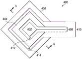
图4展示了根据本披露的触摸传感器400的替代实施例,其中,触摸传感器400能够在悬停在触摸传感器400上方的手指与来自具有小接触表面积的触笔的触摸之间进行区分而不必调整触摸传感器400的灵敏度。触摸传感器400包括第一感测电极402、传输电极404和第二感测电极406。图4中展示的实施例在功能上与图2中示出的实施例类似,但是提供了菱形形状。例如,第一感测电极402是菱形形状的,并且传输电极404基本上围绕第一感测电极402的周边。第二感测电极406基本上围绕传输电极404的周边。4 illustrates an alternative embodiment of a
在图4中展示的实施例中,传输电极404包括开口区域408,从而允许至第一感测电极402的电连接,并且第二感测电极406包括开口区域410,从而允许至第一感测电极402并且至传输电极404的电连接。第一感测电极402和传输电极404由第一间隙412分隔开。传输电极404和第二感测电极406由第二间隙414分隔开。在单层触摸屏应用中示出了图4中展示的触摸传感器400的实施例。然而,触摸传感器400可以实施在多层堆叠构型中,在这种情况下,可以消除这些开口区域408和410中的一者或多者。In the embodiment shown in FIG. 4, the
例如,传输电极404可以包括多层堆叠构型中的第一层,并且第一感测电极402和第二感测电极406可以包括多层堆叠构型中的第二层。在这种实施例中,传输电极404可以定位在第一感测电极402的整个周边的周围并且可以消除开口区域408。可替代地,第一感测电极402和传输电极404可以包括多层堆叠构型中的第一层,并且第二感测电极406可以包括多层堆叠构型中的第二层。在这种实施例中,第二感测电极406可以定位在传输电极404的整个周边的周围并且可以消除开口区域410。For example,
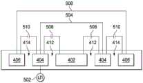
现参照图5A、图5B和图5C来讨论触摸传感器400的运行,这些图展示了沿图4的线A-A来看的触摸触感器400的横截面视图。在图5A中,线504表示传输电极404的展示部分之间的电连接,并且线506展示了第二感测电极406的展示部分之间的电连接。应理解,如关于图5A、图5B和图5C展示和描述的触摸传感器400的运行不局限于图4中展示的传感器格局400,而是还可以应用于根据本披露来设计的其他传感器格局,包括图2中展示的触摸传感器200。Operation of
运行时,控制器电路(未示出)向传输电极404施加力信号502。第一电容508存在于传输电极404与第一感测电极402之间,并且第二电容510存在于传输电极404与第二感测电极406之间。当不存在触摸时,第一电容508和第二电容510各自具有初始稳态值。当触笔或手指接近触摸传感器400时(参见图5B和图5C),第一电容508和第二电容510受到正在接近的物体的影响。确切地,当物体接近第二感测电极406时,第二电容510变化,并且当物体接近第一感测电极402时,第一电容508变化。因此,相应的第一电容508和第二电容510(或者相应的第一电容508和第二电容510的变化)表明正在接近的物体相对于第一感测电极402和第二感测电极406的位置。可以使用这个信息来检测触摸。In operation, a controller circuit (not shown) applies a
当第一电容508(或第一电容508的变化)大于第二电容510(或第二电容510的变化)时,物体与其距第二感测电极406相比而言距第一感测电极402更近。相反,当第二电容510(或第二电容510的变化)大于第一电容508(或第一电容508的变化)时,物体与其距第一感测电极402相比而言距第二感测电极406更近。因此,可以鉴于第一感测电极402和第二感测电极406在触摸传感器400中的已知位置通过考虑相应的第一电容508和第二电容510(或相应的第一电容508和第二电容510的变化)来确定触摸。此外,悬停在触摸传感器400上方的较大的物体(如手指)可以与来自具有小接触表面积的触笔的触摸区分开来而不必调整触摸传感器400的灵敏度。When the first capacitance 508 (or the change of the first capacitance 508 ) is greater than the second capacitance 510 (or the change of the second capacitance 510 ), the object is closer to the
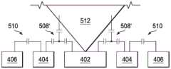
例如,图5B中展示的实施例示出了在第一感测电极402处对触摸传感器400进行触摸的1mm触笔512。由于触笔512的尺寸及其触摸位置,触笔的触摸通过在第二电容510上的最小影响而引起第一电容508的大幅度变化(在图5B中示出为变化后的第一电容508’)。如在图5B中所示,当第一电容508(或第一电容508的变化)基本上大于第二电容510(或第二电容510的变化)(例如,大20%)时,触摸物体被定位成与其距触摸传感器400的周边(第二感测电极406位于该处)相比而言距触摸传感器400的中心更近。当这种情况出现时,控制器电路表明检测到用户触摸。For example, the embodiment shown in FIG. 5B shows a 1
相反,当手指514悬停在触摸传感器400之上时(如在图5C中所示),第一电容508(或第一电容508的变化)(在图5C中示出为变化后的第一电容508’)与第二电容510(或第二电容510的变化)(在图5C中示出为变化后的第二电容510’)相似。当这种情况出现时,控制器电路认为电容变化是由于手指悬停而出现的,并且如此表明没有检测到用户触摸。Conversely, when
现参照图6,该图展示了控制器电路600的示例实施例。在图6中展示的实施例中,控制器电路600包括用于生成力信号604的电路602。控制器电路600在第一感测电极处感测第一电容606,并且在第二感测电极处感测第二电容608。第一电容606是在第一电容电压转换器电路610处感测的并且产生表明所感测的第一电容606的第一电压V1,该第一电容电压转换器电路包括运算放大器612和反馈电容器Cf1。因此,当第一电容606改变时,例如,第一电压V1响应于用户触摸而相应地改变。第二电容608是在第二电容电压转换器电路614处感测的并且产生表明所感测的第二电容608的第二电压V2,该第二电容电压转换器电路包括运算放大器616和反馈电容器Cf2。因此,当第二电容608改变时,例如,第二电压V2响应于用户触摸而相应地改变。可以使用第一电压V1和第二电压V2(或第一电压的变化ΔV1和第二电压的变化ΔV2)来检测触摸,如在以下更详细讨论的。Referring now to FIG. 6 , an example embodiment of a
在逻辑电路618接收第一电压V1和第二电压V2。一旦启动,触摸传感器(包括控制器电路600)就实现稳态,由此第一电容606和第二电容608的稳态值分别被检测到并表示为第一电压V1和第二电压V2的稳态值。在一些实施例中,存储这些稳态电压值,从而与第一电压V1和第二电压V2的实时值进行比较。例如,逻辑电路618可以对第一电压V1和第二电压V2进行采样以确定第一电压的变化ΔV1和第二电压的变化ΔV2,其中,这些变化是相对于第一电压V1和第二电压V2的稳态值来确定的。The first voltage V1 and the second voltage V2 are received at
在一些实施例中,对第一电压的变化ΔV1和第二电压的变化ΔV2进行比较以确定是否发生触摸。确切地,逻辑电路618将第一电压的变化ΔV1与第二电压的变化ΔV2进行比较并且当第一电压的变化ΔV1大幅度大于第二电压的变化ΔV2时表明检测到用户触摸。例如,在一些实施例中,逻辑电路618可以当第一电压的变化ΔV1比第二电压的变化ΔV2约大20%时表明触摸。In some embodiments, the change ΔV1 of the first voltage and the change ΔV2 of the second voltage are compared to determine whether a touch has occurred. Specifically, the
换言之,逻辑电路618相对于第一电压V1的初始值(稳态值)来确定第一电压的变化ΔV1,并且相对于第二电压V2的初始值(稳态值)来确定第二电压的变化ΔV2。逻辑电路618然后从第一电压的变化ΔV1中减去第二电压的变化ΔV2。如果差值大于阈值,则逻辑电路618表明触摸;否则,该逻辑电路表明没有触摸。该阈值可以被选择成任何值。然而在一些实施例中,该阈值等于第二电压的变化ΔV2的20%。在这个实施例中,逻辑电路618当第一电压的变化ΔV1比第二电压的变化ΔV2大20%时表明触摸。In other words, the
在其他实施例中,逻辑电路618对瞬时第一电压值V1和瞬时第二电压值V2进行采样,并且然后从第一电压V1中减去第二电压V2。如果差值大于阈值,则逻辑电路618表明触摸;否则,该逻辑电路表明没有触摸。该阈值可以被选择成任何值。然而在一些实施例中,该阈值等于第二电压V2的20%。在这个实施例中,逻辑电路618当第一电压V1比第二电压V2大20%时表明触摸。In other embodiments, the
逻辑电路618产生表明是否检测到触摸的输出信号620。在主控制器电路650接收输出信号620,该主控制器电路用于响应于(或考虑到)输出信号620而进行操作。The
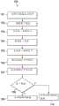
图7展示了流程图700,该流程图展示了根据前述披露的方法,该方法用于使用触摸传感器在悬停在触摸传感器上方的手指与来自具有小接触表面积的触笔的触摸之间进行区分而不必调整触摸传感器的灵敏度。在框701处,向传输电极施加力信号,由此在相应的第一感测电极和第二感测电极处引起第一电容和第二电容。在框702处,使用第一感测电极感测第一电容。在框703处,生成表明所感测的第一电容的第一感测信号。在框704处,使用第二感测电极感测第二电容。在框705处,生成表明所感测的第二电容的第二感测信号。在框706处,对第一感测信号和第二感测信号进行采样以确定第一感测信号相对于第一感测信号的稳态值的变化以及第二感测信号相对于第二感测信号的稳态值的变化。在框707处,从第一感测信号的变化中减去第二感测信号的变化。框708确定第一感测信号的变化与第二感测信号的变化之间的差是否大于阈值(例如,第二感测信号的变化的20%)。如果第一感测信号的变化与第二感测信号的变化之间的差大于阈值,则在框709处,产生表明检测触摸的信号。否则,在框710处,产生表明没有检测到触摸的信号。7 illustrates a
图8展示了流程图800,该流程图展示了根据前述披露的方法,该方法用于使用触摸传感器在悬停在触摸传感器上方的手指与来自具有小接触表面积的触笔的触摸之间进行区分而不必调整触摸传感器的灵敏度。在框801处,向传输电极施加力信号,由此在相应的第一感测电极和第二感测电极处引起第一电容和第二电容。在框802处,使用第一感测电极感测第一电容。在框803处,生成表明所感测的第一电容的第一感测信号。在框804处,使用第二感测电极感测第二电容。在框805处,生成表明所感测的第二电容的第二感测信号。在框806处,对第一感测信号和第二感测信号进行采样以确定第一感测信号和第二感测信号的瞬时值。在框807处,从第一感测信号值中减去第二感测信号值。框808确定第一感测信号值与第二感测信号值之间的差是否大于阈值(例如,第二感测信号的20%)。如果该差大于阈值,则在框809处,产生表明检测到触摸的信号。否则,在框810处,产生表明没有检测到触摸的信号。8 illustrates a
应理解,可以实施除了本文中展示和描述的那些触摸传感器设计之外的其他触摸传感器设计。例如,触摸传感器可以实施例除了具有交叉手指形或菱形的那些传感器格局之外的其他传感器格局。这种替代实施例还可以包括第一感测电极定位在传输电极与第二感测电极之间的那些实施例。It should be understood that other touch sensor designs than those shown and described herein may be implemented. For example, the touch sensor may embody other sensor configurations than those with interdigitated or diamond shapes. Such alternative embodiments may also include those in which the first sense electrode is positioned between the transmission electrode and the second sense electrode.
例如,图9展示了触摸传感器900的这样一个实施例,该触摸传感器具有定位在传输电极904与第二感测电极906之间的第一感测电极902。在图9中展示的实施例进一步包括控制器电路908。正如在本文中讨论的这些实施例,控制器电路908向传输电极904施加力信号910,从而使用第一感测电极902产生第一电容912并且使用第二感测电极906产生第二电容914。控制器908从第一感测电极902接收表明第一电容912的第一感测信号916,并且从第二感测电极906接收表明第二电容914的第二感测信号918。控制器电路908将感测信号916和918的变化进行比较,从而根据前述披露来确定触摸检测。For example, FIG. 9 illustrates one embodiment of a
已经通过示例性且非限制性的示例提供了前面的描述,是对本发明的一个或多个示例性实施例的完整且信息性描述。然而,当结合附图和所附权利要求书进行阅读时,鉴于前面的描述,各种修改和适配对于相关领域技术人员可以变得明显。然而,对本发明教导的所有此类和类似的修改将仍然落入如所附权利要求书所确定的本发明的范围之内。The foregoing description has been presented by way of illustrative and non-limiting example, and is a complete and informative description of one or more exemplary embodiments of the present invention. However, various modifications and adaptations may become apparent to those skilled in the relevant arts in view of the foregoing description, when read in conjunction with the accompanying drawings and the appended claims. However, all such and similar modifications of the teachings of this invention will still fall within the scope of this invention as determined by the appended claims.
例如,在一些实施例中,第一感测电极和传输电极可以被认为是能够独立于第二感测电极运行的单个电容式感测结构。在这种实施例中,第二感测电极基本上定位在电容式感测结构的周边周围。在其他实施例中,传输电极和第二感测电极可以被认为是能够独立于第一感测电极运行的单个电容式感测结构。在这种实施例中,第一感测电极基本上沿该电容式感测结构的内部定位,并且第二感测电极基本上定位在传输电极的周边周围。For example, in some embodiments, the first sensing electrode and the transmitting electrode may be considered a single capacitive sensing structure capable of operating independently of the second sensing electrode. In such an embodiment, the second sensing electrode is positioned substantially around the perimeter of the capacitive sensing structure. In other embodiments, the transmission electrode and the second sense electrode may be considered a single capacitive sensing structure capable of operating independently of the first sense electrode. In such an embodiment, the first sense electrodes are positioned substantially along the interior of the capacitive sensing structure, and the second sense electrodes are positioned substantially around the perimeter of the transmission electrodes.
前述传感器和方法可以结合在多种触摸传感器类型中,例如,包括零维传感器、一维传感器、二维传感器和轮传感器。The aforementioned sensors and methods may be incorporated into a variety of touch sensor types, including, for example, zero-dimensional sensors, one-dimensional sensors, two-dimensional sensors, and wheel sensors.
Claims (29)
Applications Claiming Priority (3)
| Application Number | Priority Date | Filing Date | Title |
|---|---|---|---|
| US14/852,847 | 2015-09-14 | ||
| US14/852,847US10416802B2 (en) | 2015-09-14 | 2015-09-14 | Mutual hover protection for touchscreens |
| CN201610822838.8ACN106527831B (en) | 2015-09-14 | 2016-09-13 | Mutual hover protection for touchscreens |
Related Parent Applications (1)
| Application Number | Title | Priority Date | Filing Date |
|---|---|---|---|
| CN201610822838.8ADivisionCN106527831B (en) | 2015-09-14 | 2016-09-13 | Mutual hover protection for touchscreens |
Publications (2)
| Publication Number | Publication Date |
|---|---|
| CN111610895Atrue CN111610895A (en) | 2020-09-01 |
| CN111610895B CN111610895B (en) | 2025-05-16 |
Family
ID=58236899
Family Applications (3)
| Application Number | Title | Priority Date | Filing Date |
|---|---|---|---|
| CN201621055069.5UActiveCN206301315U (en) | 2015-09-14 | 2016-09-13 | Capacitive sensing structure and capacitive sensing circuit |
| CN202010421171.7AActiveCN111610895B (en) | 2015-09-14 | 2016-09-13 | Mutual hover protection for touch screens |
| CN201610822838.8AActiveCN106527831B (en) | 2015-09-14 | 2016-09-13 | Mutual hover protection for touchscreens |
Family Applications Before (1)
| Application Number | Title | Priority Date | Filing Date |
|---|---|---|---|
| CN201621055069.5UActiveCN206301315U (en) | 2015-09-14 | 2016-09-13 | Capacitive sensing structure and capacitive sensing circuit |
Family Applications After (1)
| Application Number | Title | Priority Date | Filing Date |
|---|---|---|---|
| CN201610822838.8AActiveCN106527831B (en) | 2015-09-14 | 2016-09-13 | Mutual hover protection for touchscreens |
Country Status (2)
| Country | Link |
|---|---|
| US (2) | US10416802B2 (en) |
| CN (3) | CN206301315U (en) |
Families Citing this family (5)
| Publication number | Priority date | Publication date | Assignee | Title |
|---|---|---|---|---|
| US10416802B2 (en)* | 2015-09-14 | 2019-09-17 | Stmicroelectronics Asia Pacific Pte Ltd | Mutual hover protection for touchscreens |
| KR20170084558A (en)* | 2016-01-12 | 2017-07-20 | 삼성전자주식회사 | Electronic Device and Operating Method Thereof |
| DE102017215333A1 (en)* | 2017-09-01 | 2019-03-07 | Witte Automotive Gmbh | Capacitive sensor arrangement and vehicle exterior handle |
| CN111694435B (en)* | 2020-06-16 | 2024-02-02 | 石亦磊 | Wearable touch detection method based on inertial sensing unit |
| CN112612384B (en)* | 2021-01-07 | 2025-07-22 | 无锡变格新材料科技有限公司 | Touch control device |
Citations (6)
| Publication number | Priority date | Publication date | Assignee | Title |
|---|---|---|---|---|
| US20110096025A1 (en)* | 2009-10-27 | 2011-04-28 | Perceptive Pixel Inc. | Projected Capacitive Touch Sensing |
| CN102314275A (en)* | 2010-07-01 | 2012-01-11 | 安森美半导体贸易公司 | The electrostatic capacity type touch sensor |
| CN102483673A (en)* | 2009-07-10 | 2012-05-30 | 苹果公司 | Touch and hover sensing |
| JP2012164082A (en)* | 2011-02-04 | 2012-08-30 | Semiconductor Components Industries Llc | Electrostatic capacity type touch sensor |
| US20140009428A1 (en)* | 2012-07-03 | 2014-01-09 | Sharp Kabushiki Kaisha | Capacitive touch panel with height determination function |
| CN104516716A (en)* | 2015-01-13 | 2015-04-15 | 深圳市亚耕电子科技有限公司 | Electronic equipment, capacitive sensing system and detection method of capacitive sensing system |
Family Cites Families (8)
| Publication number | Priority date | Publication date | Assignee | Title |
|---|---|---|---|---|
| TWI317957B (en)* | 2008-05-05 | 2009-12-01 | Generalplus Technology Inc | Capacitive sensor |
| CN102810031A (en)* | 2011-05-30 | 2012-12-05 | 升达科技股份有限公司 | Multi-point touch detection method and device |
| US8937607B2 (en)* | 2012-03-30 | 2015-01-20 | Sharp Kabushiki Kaisha | Capacitive touch panel with dynamically allocated electrodes |
| KR101439855B1 (en)* | 2013-01-25 | 2014-09-17 | 주식회사 하이딥 | Touch screen controller and method for controlling thereof |
| CN105094395A (en)* | 2014-05-04 | 2015-11-25 | 宸鸿科技(厦门)有限公司 | Touch control apparatus |
| US9304643B2 (en)* | 2014-06-24 | 2016-04-05 | Synaptics Incorporated | Classifying input objects interacting with a capacitive button |
| WO2016022778A1 (en)* | 2014-08-07 | 2016-02-11 | 3M Innovative Properties Company | Force-sensing capacitor elements, deformable membranes and electronic devices fabricated therefrom |
| US10416802B2 (en)* | 2015-09-14 | 2019-09-17 | Stmicroelectronics Asia Pacific Pte Ltd | Mutual hover protection for touchscreens |
- 2015
- 2015-09-14USUS14/852,847patent/US10416802B2/enactiveActive
- 2016
- 2016-09-13CNCN201621055069.5Upatent/CN206301315U/enactiveActive
- 2016-09-13CNCN202010421171.7Apatent/CN111610895B/enactiveActive
- 2016-09-13CNCN201610822838.8Apatent/CN106527831B/enactiveActive
- 2019
- 2019-08-06USUS16/532,872patent/US10942601B2/enactiveActive
Patent Citations (7)
| Publication number | Priority date | Publication date | Assignee | Title |
|---|---|---|---|---|
| CN102483673A (en)* | 2009-07-10 | 2012-05-30 | 苹果公司 | Touch and hover sensing |
| US20110096025A1 (en)* | 2009-10-27 | 2011-04-28 | Perceptive Pixel Inc. | Projected Capacitive Touch Sensing |
| CN102314275A (en)* | 2010-07-01 | 2012-01-11 | 安森美半导体贸易公司 | The electrostatic capacity type touch sensor |
| JP2012164082A (en)* | 2011-02-04 | 2012-08-30 | Semiconductor Components Industries Llc | Electrostatic capacity type touch sensor |
| US20140009428A1 (en)* | 2012-07-03 | 2014-01-09 | Sharp Kabushiki Kaisha | Capacitive touch panel with height determination function |
| CN104428741A (en)* | 2012-07-03 | 2015-03-18 | 夏普株式会社 | A capacitive touch panel with height determination function |
| CN104516716A (en)* | 2015-01-13 | 2015-04-15 | 深圳市亚耕电子科技有限公司 | Electronic equipment, capacitive sensing system and detection method of capacitive sensing system |
Also Published As
| Publication number | Publication date |
|---|---|
| US20170075469A1 (en) | 2017-03-16 |
| US10416802B2 (en) | 2019-09-17 |
| US20190361564A1 (en) | 2019-11-28 |
| CN106527831B (en) | 2020-06-16 |
| CN106527831A (en) | 2017-03-22 |
| CN206301315U (en) | 2017-07-04 |
| US10942601B2 (en) | 2021-03-09 |
| CN111610895B (en) | 2025-05-16 |
Similar Documents
| Publication | Publication Date | Title |
|---|---|---|
| US10942601B2 (en) | Mutual hover protection for touchscreens | |
| US9965079B2 (en) | Pressure-sensitive touch screen and touch display screen and electronic device | |
| KR102404549B1 (en) | Techniques for handling unintentional touch inputs on a touch-sensitive surface | |
| KR102719196B1 (en) | Stylus soft touch detection | |
| KR102110183B1 (en) | Method of calibrating sensitivity of a touch input device and touch input device employing the same | |
| JP5122560B2 (en) | Fingertip touch recognition for digitizers | |
| US20130027344A1 (en) | Apparatus Including a Touch-Sensitive Interface Including a Serpentine Electrode Pattern | |
| US20130088448A1 (en) | Touch screen panel | |
| US10423268B2 (en) | System and method for detecting grounding state of a touch enabled computing device | |
| EP3750039B1 (en) | Touch detection on an ungrounded pen enabled device | |
| JP7294896B2 (en) | Touch detection circuits, input devices, electronic devices | |
| TWI526952B (en) | Touch capacitive device and object identifying method of the capacitive touch device | |
| JP2010113445A (en) | Touch panel and method of detecting operation | |
| EP3652625A1 (en) | Method for touch detection enhancement based on identifying a cover film on a touch-screen | |
| US20150212649A1 (en) | Touchpad input device and touchpad control program | |
| KR101473184B1 (en) | A capacitive touch screen for integrated of fingerprint recognition of swipe type | |
| JP2008165575A (en) | Touch panel device | |
| US9310945B2 (en) | Touch-sensing display device | |
| CN105677121B (en) | Touch-control decision maker and method and display device | |
| CN105468214A (en) | Location based object classification | |
| TW201415301A (en) | Stylus, touch sensitive device and method for recognizing type of input element in contact with capacitive touch screen | |
| KR101763589B1 (en) | Sensor device of capacitance type | |
| US11561111B2 (en) | Displacement sensing | |
| CN209514585U (en) | A kind of touch screen | |
| US10558306B2 (en) | In-cell touch apparatus and a water mode detection method thereof |
Legal Events
| Date | Code | Title | Description |
|---|---|---|---|
| PB01 | Publication | ||
| PB01 | Publication | ||
| SE01 | Entry into force of request for substantive examination | ||
| SE01 | Entry into force of request for substantive examination | ||
| GR01 | Patent grant | ||
| GR01 | Patent grant |