CN111604886A - A kind of ankle joint power-assisted exoskeleton device and power-assisted shoes - Google Patents
A kind of ankle joint power-assisted exoskeleton device and power-assisted shoesDownload PDFInfo
- Publication number
- CN111604886A CN111604886ACN202010378890.5ACN202010378890ACN111604886ACN 111604886 ACN111604886 ACN 111604886ACN 202010378890 ACN202010378890 ACN 202010378890ACN 111604886 ACN111604886 ACN 111604886A
- Authority
- CN
- China
- Prior art keywords
- leg
- assembly
- user
- foot
- frame
- Prior art date
- Legal status (The legal status is an assumption and is not a legal conclusion. Google has not performed a legal analysis and makes no representation as to the accuracy of the status listed.)
- Pending
Links
- 210000000544articulatio talocruralisAnatomy0.000titleclaimsabstractdescription47
- 210000002683footAnatomy0.000claimsabstractdescription126
- 230000005489elastic deformationEffects0.000claimsabstractdescription6
- 210000003423ankleAnatomy0.000claimsdescription9
- 230000000712assemblyEffects0.000claimsdescription4
- 238000000429assemblyMethods0.000claimsdescription4
- 238000000034methodMethods0.000abstractdescription19
- 210000003205muscleAnatomy0.000abstractdescription11
- 230000000694effectsEffects0.000abstractdescription3
- 238000010586diagramMethods0.000description12
- 244000309466calfSpecies0.000description11
- 208000027418Wounds and injuryDiseases0.000description3
- 238000004146energy storageMethods0.000description2
- 230000006835compressionEffects0.000description1
- 238000007906compressionMethods0.000description1
- 230000006378damageEffects0.000description1
- 208000014674injuryDiseases0.000description1
- 210000001503jointAnatomy0.000description1
- 238000004519manufacturing processMethods0.000description1
- 230000009466transformationEffects0.000description1
Images


Classifications
- B—PERFORMING OPERATIONS; TRANSPORTING
- B25—HAND TOOLS; PORTABLE POWER-DRIVEN TOOLS; MANIPULATORS
- B25J—MANIPULATORS; CHAMBERS PROVIDED WITH MANIPULATION DEVICES
- B25J9/00—Programme-controlled manipulators
- B25J9/0006—Exoskeletons, i.e. resembling a human figure
- A—HUMAN NECESSITIES
- A43—FOOTWEAR
- A43B—CHARACTERISTIC FEATURES OF FOOTWEAR; PARTS OF FOOTWEAR
- A43B7/00—Footwear with health or hygienic arrangements
- A43B7/14—Footwear with health or hygienic arrangements with foot-supporting parts
- A43B7/18—Joint supports, e.g. instep supports
- A43B7/20—Ankle-joint supports or holders
Landscapes
- Engineering & Computer Science (AREA)
- Robotics (AREA)
- Mechanical Engineering (AREA)
- Health & Medical Sciences (AREA)
- Epidemiology (AREA)
- General Health & Medical Sciences (AREA)
- Public Health (AREA)
- Rehabilitation Tools (AREA)
Abstract
Translated fromChinese
Description
Translated fromChinese技术领域technical field
本发明涉及外骨骼助力技术领域,尤其涉及一种踝关节助力外骨骼装置及助力鞋。The invention relates to the technical field of exoskeleton assisting, in particular to an ankle joint assisting exoskeleton device and assisting shoes.
背景技术Background technique
工业外骨骼是一种新兴的工业用可穿戴式助力设备,其中,穿戴式行走助力外骨骼能够为用户提供行走的随动支撑力,在自由跟随用户运动的情况下为用户提供助力。The industrial exoskeleton is a new type of industrial wearable power-assisting equipment, in which the wearable walking-assisting exoskeleton can provide the user with a follow-up support force for walking, and provide assistance to the user while freely following the user's movement.
目前,行走助力外骨骼一般分为主动式助力外骨骼和被动式外骨骼;其中,主动式外骨骼一般具有电机或液压等力输出系统,主动提供行走时关节所需要的力;被动式外骨骼是通过储存用户在行走过程中做负功的能量,然后在用户需要做主动功时,反馈给用户;但主动式外骨骼往往系统较重,给用户带来较大的额外消耗,且主动式外骨骼还受电量的约束;而被动式外骨骼则相对较轻,且可靠性高。因此,被动式外骨骼受到人们的广泛关注。At present, walking-assisted exoskeletons are generally divided into active-assisted exoskeletons and passive exoskeletons; among them, active exoskeletons generally have a motor or hydraulic force output system, which actively provides the force required by the joints when walking; passive exoskeletons are driven by Stores the energy of the user's negative work during walking, and then feeds it back to the user when the user needs to do active work; however, the active exoskeleton often has a heavy system, which brings greater additional consumption to the user, and the active exoskeleton It is also constrained by power; passive exoskeletons are relatively light and reliable. Therefore, passive exoskeletons have received extensive attention.
然而,现有的被动式外骨骼是通过柔性绑带直接绑缚在用户的小腿肚上,且弹性件的一端是直接连接在柔性绑带上,为保证弹性件能够在用户行走过程中正常存储或释放能量,需要将柔性绑带紧紧绑缚在用户的小腿肚上,但这样会严重影响用户腿部肌肉的发力。However, the existing passive exoskeleton is directly tied to the user's calf through a flexible strap, and one end of the elastic member is directly connected to the flexible strap. To release energy, the flexible straps need to be tightly tied to the user's calf, but this will seriously affect the strength of the user's leg muscles.
发明内容SUMMARY OF THE INVENTION
本申请提供一种踝关节助力外骨骼装置及助力鞋,该踝关节助力外骨骼装置不仅能够存储用户行走过程中的负功,并在需要做正功时反馈给用户,以为用户提供行走助力,且能够大大降低对用户腿部肌肉发力的影响。The present application provides an ankle joint power-assisted exoskeleton device and a power-assisted shoe. The ankle joint power-assisted exoskeleton device can not only store the negative work during the user's walking process, but also feed back to the user when positive work needs to be done, so as to provide walking assistance for the user, And can greatly reduce the impact on the user's leg muscles.
为解决上述技术问题,本申请采用的一个技术方案是:提供一种踝关节助力外骨骼装置。该装置包括腿部组件、脚部组件和弹性件;其中,腿部组件包括腿部框架,所述腿部框架用于绕设在用户的腿部;脚部组件,与所述腿部框架转动连接,用于穿戴在所述用户的脚部;弹性件,设置在所述腿部框架和所述脚部组件的连接处,用于在所述腿部框架和所述脚部组件之间的夹角在预设角度范围内变化时发生弹性形变或恢复自然状态,以储存或释放能量。In order to solve the above technical problems, a technical solution adopted in the present application is to provide an ankle joint power-assisted exoskeleton device. The device includes a leg assembly, a foot assembly and an elastic part; wherein the leg assembly includes a leg frame, the leg frame is used to be arranged around the user's leg; the foot assembly rotates with the leg frame connection, for wearing on the user's foot; elastic member, arranged at the connection of the leg frame and the foot assembly, for the connection between the leg frame and the foot assembly When the included angle changes within a preset angle range, elastic deformation occurs or returns to its natural state to store or release energy.
其中,所述腿部框架呈半包围结构;且所述腿部组件还包括第一绑带,所述第一绑带与所述腿部框架连接,用于将所述腿部框架与所述用户的腿部固定。Wherein, the leg frame is in a semi-enclosed structure; and the leg assembly further includes a first strap, the first strap is connected with the leg frame, and is used for connecting the leg frame with the The user's legs are fixed.
其中,所述第一绑带包括相对设置的第一左绑带和第一右绑带,所述第一左绑带和所述第一右绑带分别设置在所述腿部框架的两侧,以通过所述第一左绑带和所述第一右绑带将所述腿部框架与所述用户的腿部固定。Wherein, the first strap includes a first left strap and a first right strap that are oppositely arranged, and the first left strap and the first right strap are respectively arranged on both sides of the leg frame , to fix the leg frame with the user's leg by the first left strap and the first right strap.
其中,所述脚部组件包括脚部框架和第二绑带;其中,脚部框架用于与所述用户的鞋底接触;第二绑带与所述脚部框架连接,用于绕设所述用户的鞋面以将所述脚部框架与所述用户的鞋体固定。Wherein, the foot assembly includes a foot frame and a second strap; wherein, the foot frame is used for contacting the sole of the user; the second strap is connected with the foot frame for wrapping the a user's upper to secure the foot frame to the user's shoe body.
其中,所述脚部框架朝向所述用户的鞋底的一侧表面设置有若干防滑凸起。Wherein, a side surface of the foot frame facing the user's sole is provided with several anti-slip protrusions.
其中,所述第二绑带包括第二左绑带和第二右绑带,所述第二左绑带和第二右绑带分别设置在所述脚部框架的相对两侧,以通过所述第二左绑带和第二右绑带将所述脚部框架与所述用户的鞋体固定。Wherein, the second strap includes a second left strap and a second right strap, and the second left strap and the second right strap are respectively arranged on opposite sides of the foot frame to pass through the The second left strap and the second right strap secure the foot frame to the user's shoe body.
其中,所述弹性件为卷簧,所述腿部框架用于与所述脚部组件连接的部位设置有一弧形槽,所述脚部组件用于与所述腿部框架连接的部位设置有一固定孔,所述卷簧的一端伸入所述弧形槽中,以与所述腿部组件滑动连接,所述卷簧的另一端伸入所述固定孔中,以与所述脚部组件固定连接。Wherein, the elastic member is a coil spring, the part of the leg frame for connecting with the foot assembly is provided with an arc-shaped groove, and the part of the foot assembly for connecting with the leg frame is provided with a a fixing hole, one end of the coil spring extends into the arc-shaped groove to be slidably connected with the leg assembly, and the other end of the coil spring extends into the fixing hole to connect with the foot assembly Fixed connection.
其中,还包括两组连接组件,用于连接所述腿部组件、所述弹性件和所述脚部组件。Wherein, two sets of connecting assemblies are also included for connecting the leg assemblies, the elastic members and the foot assemblies.
其中,所述腿部组件用于与所述脚部组件连接的部位还设置有旋转孔,所述脚部组件用于与所述腿部组件连接的部位还设置有一连接孔,所述连接组件包括转动轴和固定件;其中,转动轴依次穿设在所述旋转孔、所述卷簧和所述连接孔中,且所述腿部框架可通过所述旋转孔绕所述转动轴旋转;固定件与所述转动轴配合,以将所述腿部组件、所述弹性件和所述脚部组件固定连接。Wherein, the part of the leg assembly for connecting with the foot assembly is further provided with a rotation hole, the part of the foot assembly for connecting with the leg assembly is further provided with a connecting hole, and the connecting assembly is further provided with a connecting hole. It includes a rotating shaft and a fixing piece; wherein, the rotating shaft is successively penetrated in the rotating hole, the coil spring and the connecting hole, and the leg frame can rotate around the rotating shaft through the rotating hole; The fixing member is matched with the rotating shaft to fixedly connect the leg assembly, the elastic member and the foot assembly.
为解决上述技术问题,本申请采用的另一个技术方案是:提供一种助力鞋,包括:鞋本体以及踝关节助力外骨骼装置,其中,踝关节助力外骨骼装置为上述所涉及的踝关节助力外骨骼装置。In order to solve the above-mentioned technical problem, another technical solution adopted in the present application is to provide a kind of power-assisted shoe, comprising: a shoe body and an ankle-joint power-assisted exoskeleton device, wherein the ankle-joint power-assisted exoskeleton device is the above-mentioned ankle joint power-assisted device Exoskeleton device.
本申请提供的踝关节助力外骨骼装置及助力鞋,该踝关节助力外骨骼装置通过设置腿部组件,将腿部组件设置成包括腿部框架,以通过腿部框架绕设在用户的腿部,相比于现有技术中通过柔性绑带直接绑缚在用户的腿部,可减小腿部组件对用户腿部的束缚力,从而能够降低腿部组件对用户腿部肌肉发力的影响;同时,通过设置脚部组件,以使脚部组件可穿戴在用户的脚部;另外,通过设置弹性件,并将弹性件设置在腿部框架和脚部组件的连接处,以在腿部组件和脚部组件之间的夹角在预设角度范围内变化时,弹性件能够发生弹性形变或恢复自然伸长状态,从而存储或释放能量;其中,由于腿部组件与脚部组件转动连接,且弹性件设置在腿部组件和脚部组件的连接处,从而在用户行走过程中,当用户的腿部和脚部之间的夹角发生变化时,可同时带动腿部组件和脚部组件之间的夹角发生变化,进而可使设置在二者连接处的弹性件发生弹性形变或恢复自然伸长状态,以存储或释放能量,从而为用户行走提供助力;此外,由于弹性件是基于腿部组件和脚部组件之间的夹角变化来引起自身的弹性形变,且在形变过程中弹性件不会对腿部组件产生一朝向脚部组件的牵引力,相比于现有技术中将弹性件直接连接在柔性绑带上,该装置无需因弹性件的牵引力而加大腿部框架与用户腿部之间的作用力,从而能够进一步降低腿部组件对用户腿部肌肉发力的影响。The ankle joint power-assisted exoskeleton device and power-assisted shoes provided by the present application, the ankle joint power-assisted exoskeleton device is provided with a leg assembly, and the leg assembly is set to include a leg frame, so as to be wound around the user's leg through the leg frame Compared with the prior art, the flexible straps are directly tied to the user's leg, which can reduce the binding force of the leg assembly on the user's leg, thereby reducing the impact of the leg assembly on the user's leg muscles. At the same time, by arranging the foot assembly, so that the foot assembly can be worn on the user's feet; in addition, by arranging elastic parts, and the elastic parts are arranged at the connection between the leg frame and the foot assembly, so that the leg parts can be worn on the feet of the user. When the angle between the component and the foot component changes within a preset angle range, the elastic member can elastically deform or restore to a natural elongation state, thereby storing or releasing energy; wherein, due to the rotational connection between the leg component and the foot component , and the elastic member is arranged at the connection between the leg assembly and the foot assembly, so that when the angle between the user's leg and the foot changes during the user's walking process, the leg assembly and the foot can be driven at the same time. The angle between the components changes, so that the elastic member arranged at the connection between the two can be elastically deformed or restored to a natural elongation state to store or release energy, thereby providing assistance for the user to walk; in addition, because the elastic member is It causes its own elastic deformation based on the change of the angle between the leg assembly and the foot assembly, and the elastic member will not generate a traction force on the leg assembly toward the foot assembly during the deformation process, compared with the prior art. The elastic part is directly connected to the flexible strap, and the device does not need to increase the force between the leg frame and the user's leg due to the traction force of the elastic part, thereby further reducing the force exerted by the leg assembly on the user's leg muscles. influences.
附图说明Description of drawings
图1为本申请一实施例提供的踝关节助力外骨骼装置的分解示意图;FIG. 1 is an exploded schematic diagram of an ankle-assisted exoskeleton device provided by an embodiment of the application;
图2为本申请一实施例提供的踝关节助力外骨骼装置的主视图;2 is a front view of an ankle-assisted exoskeleton device provided by an embodiment of the application;
图3为本申请一实施例提供的踝关节助力外骨骼装置的侧视图;3 is a side view of an ankle-assisted exoskeleton device provided by an embodiment of the present application;
图4为本申请一实施例提供的踝关节助力外骨骼装置的俯视图;4 is a top view of an ankle-assisted exoskeleton device provided by an embodiment of the present application;
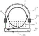
图5为本申请一实施例提供的腿部框架的结构示意图;5 is a schematic structural diagram of a leg frame provided by an embodiment of the application;
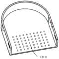
图6为本申请一实施例提供的底板的结构示意图;6 is a schematic structural diagram of a bottom plate provided by an embodiment of the present application;
图7为本申请一实施例提供的支撑架的结构示意图;7 is a schematic structural diagram of a support frame provided by an embodiment of the present application;
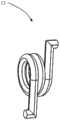
图8为本申请一实施例提供的弹性件的结构示意图;8 is a schematic structural diagram of an elastic member provided by an embodiment of the present application;
图9为本申请一实施例提供的用户行走过程中不同阶段所对应的踝关节角度变化示意图;9 is a schematic diagram of changes in ankle joint angles corresponding to different stages in a user's walking process according to an embodiment of the present application;
图10为本申请一实施例提供的转动销轴的结构示意图。FIG. 10 is a schematic structural diagram of a rotating pin shaft provided by an embodiment of the application.
具体实施方式Detailed ways
下面将结合本申请实施例中的附图,对本申请实施例中的技术方案进行清楚、完整地描述,显然,所描述的实施例仅是本申请的一部分实施例,而不是全部的实施例。基于本申请中的实施例,本领域普通技术人员在没有做出创造性劳动前提下所获得的所有其他实施例,都属于本申请保护的范围。The technical solutions in the embodiments of the present application will be clearly and completely described below with reference to the drawings in the embodiments of the present application. Obviously, the described embodiments are only a part of the embodiments of the present application, but not all of the embodiments. Based on the embodiments in the present application, all other embodiments obtained by those of ordinary skill in the art without creative efforts shall fall within the protection scope of the present application.
本申请中的术语“第一”、“第二”、“第三”仅用于描述目的,而不能理解为指示或暗示相对重要性或者隐含指明所指示的技术特征的数量。由此,限定有“第一”、“第二”、“第三”的特征可以明示或者隐含地包括至少一个该特征。本申请的描述中,“多个”的含义是至少两个,例如两个,三个等,除非另有明确具体的限定。本申请实施例中所有方向性指示(诸如上、下、左、右、前、后……)仅用于解释在某一特定姿态(如附图所示)下各部件之间的相对位置关系、运动情况等,如果该特定姿态发生改变时,则该方向性指示也相应地随之改变。此外,术语“包括”和“具有”以及它们任何变形,意图在于覆盖不排他的包含。例如包含了一系列步骤或单元的过程、方法、系统、产品或设备没有限定于已列出的步骤或单元,而是可选地还包括没有列出的步骤或单元,或可选地还包括对于这些过程、方法、产品或设备固有的其它步骤或单元。The terms "first", "second" and "third" in this application are only used for descriptive purposes, and should not be construed as indicating or implying relative importance or implying the number of indicated technical features. Thus, a feature defined as "first", "second", "third" may expressly or implicitly include at least one of that feature. In the description of the present application, "a plurality of" means at least two, such as two, three, etc., unless otherwise expressly and specifically defined. All directional indications (such as up, down, left, right, front, rear...) in the embodiments of the present application are only used to explain the relative positional relationship between components under a certain posture (as shown in the accompanying drawings). , motion situation, etc., if the specific posture changes, the directional indication also changes accordingly. Furthermore, the terms "comprising" and "having", and any variations thereof, are intended to cover non-exclusive inclusion. For example, a process, method, system, product or device comprising a series of steps or units is not limited to the listed steps or units, but optionally also includes unlisted steps or units, or optionally also includes For other steps or units inherent to these processes, methods, products or devices.
在本文中提及“实施例”意味着,结合实施例描述的特定特征、结构或特性可以包含在本申请的至少一个实施例中。在说明书中的各个位置出现该短语并不一定均是指相同的实施例,也不是与其它实施例互斥的独立的或备选的实施例。本领域技术人员显式地和隐式地理解的是,本文所描述的实施例可以与其它实施例相结合。Reference herein to an "embodiment" means that a particular feature, structure, or characteristic described in connection with the embodiment can be included in at least one embodiment of the present application. The appearances of the phrase in various places in the specification are not necessarily all referring to the same embodiment, nor a separate or alternative embodiment that is mutually exclusive of other embodiments. It is explicitly and implicitly understood by those skilled in the art that the embodiments described herein may be combined with other embodiments.
下面结合附图和实施例对本申请进行详细的说明。The present application will be described in detail below with reference to the accompanying drawings and embodiments.
请参阅图1至图4,其中,图1为本申请一实施例提供的踝关节助力外骨骼装置的分解示意图;图2为本申请一实施例提供的踝关节助力外骨骼装置的主视图;图3为本申请一实施例提供的踝关节助力外骨骼装置的侧视图;图4为本申请一实施例提供的踝关节助力外骨骼装置的俯视图;在本实施例中,提供一种踝关节助力外骨骼装置10,该装置10包括腿部组件11、脚部组件12、弹性件13和连接组件14。Please refer to FIGS. 1 to 4, wherein, FIG. 1 is an exploded schematic view of an ankle joint power-assisted exoskeleton device provided by an embodiment of the application; FIG. 2 is a front view of an ankle joint power-assisted exoskeleton device provided by an embodiment of the application; FIG. 3 is a side view of an ankle-assisted exoskeleton device provided by an embodiment of the application; FIG. 4 is a top view of an ankle-assisted exoskeleton device provided by an embodiment of the application; in this embodiment, an ankle joint is provided The power-assisted
其中,腿部组件11包括腿部框架111,腿部框架111用于绕设在用户的腿部,相比于现有技术中通过柔性绑带直接绑缚在用户的腿部,可减小腿部组件11对用户腿部的束缚力,从而能够降低腿部组件11对用户腿部肌肉发力的影响。Wherein, the leg assembly 11 includes a
在一实施例中,参见图1,腿部组件11包括腿部框架111和第一绑带112;其中,参见图5,图5为本申请一实施例提供的腿部框架的结构示意图;腿部框架111具体可为半包围结构,用于绕设在用户的小腿肚上,以减小对小腿肌肉的束缚力;第一绑带112与腿部框架111连接,用于将腿部框架111与用户的腿部固定。In an embodiment, referring to FIG. 1 , the leg assembly 11 includes a
其中,参见图5,腿部框架111具体可包括框架主体311和两个突出部312;其中,框架主体311的形状与用户的腿肚的形状匹配,用于绕设在用户的腿肚上;框架主体311为一弯折的片状结构,其形状大致为矩形;两个突出部312相对设置在框架主体311靠近脚部组件12的一侧,且两个突出部312分别位于两个拐角处并朝向远离框架主体311的方向延伸,用于在穿戴过程中使脚部组件11和腿部组件12的连接处与用户的踝关节所在的位置对应;另外,两个突出部312的第一边3121与框架主体311的侧边3111形成L型,两个突出部312与第一边3121相对的第二边3122与框架主体311的底边3112连接,使得该腿部框架111展开时靠近脚部组件12的一边呈一弧形;此外,两个突出部312与支撑架1212连接后,框架主体311的底边3112与底板1211之间间隔设置,从而可以避免行走时框架主体311的底边3112对脚踝的蹭伤;上述通过设置突出部312能够避免为了在穿戴过程中使脚部组件11和腿部组件12的连接处与用户的踝关节所在的位置对应,而增加框架主体311的弧形侧壁的问题发生,从而可进一步降低腿部框架111对用户腿部的束缚;具体的,突出部312可与框架主体311一体成型。5, the
进一步地,突出部312朝向脚部组件12的一端具有延伸部313,延伸部313距离脚部组件12的距离小于框架主体311距离脚部组件12的距离,以在具体实施例中,能够通过该延伸部313使腿部组件11与脚部组件12的连接处位于用户的踝关节所在的位置,从而利用用户行走过程中踝关节角度的变化来引起脚部组件11与腿部组件12之间夹角的变化;同时,通过设置该延伸部313,不仅节省生产成本,且可避免在转动过程中出现框架主体311蹭伤用户腿部的问题。可以理解的是,在该实施例中,腿部组件11具体可通过该延伸部313与脚部组件12转动连接。Further, one end of the protruding portion 312 facing the
在一具体实施例中,第一绑带112呈一长条状结构,第一绑带112的一端固定连接在腿部框架111的一侧,第一绑带112的另一端为活动端,该活动端与腿部框架111的另一侧活动连接,以方便用户穿戴,同时在穿戴好之后,通过调节该活动端以对腿部框架111进行固定。具体的,腿部框架111的另一侧可设置有一通孔,第一绑带112的活动端可穿进该通孔并进行系绑,以对腿部框架111进行固定;当然,在其它实施例中,第一绑带112也可为弹性带,弹性带的两端固定连接在腿部框架111的两侧。In a specific embodiment, the
在另一具体实施例中,第一绑带112包括第一左绑带1121和第一右绑带1122,具体可参见图1和图2,第一左绑带1121和第一右绑带1122相对设置在腿部框架111的两侧,且第一左绑带1121和第一右绑带1122的一端与腿部框架111连接,第一左绑带1121和第一右绑带1122的另一端可绑合在一起,以通过第一左绑带1121和第一右绑带1122将腿部框架111与用户的腿部固定;具体的,第一左绑带1121和第一右绑带1122均为两条,且每个第一左绑带1121上设置有一环形扣,第一右绑带1122具体可穿进该环形扣中以与第一左绑带1121绑合;当然,第一左绑带1121和第一右绑带1122也可直接系在一起,本实施例对此并不加以限制。In another specific embodiment, the
进一步地,在其它具体实施例中,上述腿部框架11和脚部组件12之间还可设置一弹簧或松紧带,以进一步提高该装置10的储能作用,从而在需要做正功时能够释放更多的正能量,进而为用户行走提供助力。具体的,弹簧或松紧带的一端可拆卸固定于腿部框架111的底边3112,另一端可拆卸固定于脚部组件12。Further, in other specific embodiments, a spring or an elastic band may be arranged between the above-mentioned leg frame 11 and the
当然,在另一实施例中,腿部框架111也可为全包围结构;具体的,腿部框架111包括可开合第一弧形槽体和第二弧形槽体,其中,第一弧形槽体的形状与用户的腿肚的形状匹配,以在穿戴过程中绕设在用户的腿肚上;第二弧形槽体与第一弧形槽体配合以将腿部组件11与用户的腿部固定;具体的,当需要穿戴该腿部框架111时,将第一弧形槽体与第二弧形槽体打开以使用户的腿部伸入该第一弧形槽体中,之后再将第二弧形槽体与第一弧形槽体扣合以进行固定;其中,具体可采用卡扣或卡箍的形式进行扣合;而当需要拆除该腿部框架111时,则将第一弧形槽体与第二弧形槽体打开以使用户的腿部移出该第一弧形槽体中即可。具体的,为了防止第二弧形槽体对用户的腿部造成蹭伤,第一弧形槽体和第二弧形槽体可采用橡胶材质。具体的,第二弧形槽体可沿垂直于槽体延伸的方向打开或扣合。Of course, in another embodiment, the
其中,脚部组件12与腿部框架111转动连接,用于穿戴在用户的脚部。在一具体实施例中,脚部组件12具体穿戴在用户的鞋体上。Wherein, the
具体的,脚部组件12包括脚部框架121和第二绑带122;其中,脚部框架121用于与用户的鞋底接触;第二绑带122与脚部框架121连接,用于绕设用户的鞋面以将脚部框架121与用户穿戴的鞋体固定。Specifically, the
在一实施例中,参见图1,脚部框架121可包括底板1211和两个支撑架1212。In one embodiment, referring to FIG. 1 , the
其中,底板1211用于与用户的鞋底接触,第二绑带122具体与底板1211连接,以将底板1211与用户的鞋体固定;具体的,参见图6,图6为本申请一实施例提供的底板的结构示意图;底板1211的形状与用户鞋底,尤其是鞋跟的形状匹配;且底板1211朝向用户鞋底的一侧表面可设置有若干防滑凸起12111,以增大底板1211与用户鞋底之间的摩擦力,避免滑移;当然,底板1211朝向用户鞋底的一侧表面也可设置若干防滑凹坑,本实施例对此并不加以限制。The
其中,参见图1和图7,其中,图7为本申请一实施例提供的支撑架的结构示意图;支撑架1212具体可为一长条状结构,两个支撑架1212具体设置在底板1211的相对两侧,用于连接并支撑腿部组件11,同时垫高腿部组件11,以使腿部组件11和脚部组件12的连接处与用户踝关节对应,从而方便该装置10为踝关节运动提供助力。在一具体实施例中,支撑架1212的一端与底板1211可拆卸式连接,支撑架1212的另一端通过连接组件14与腿部组件11的延伸部313转动连接;在另一具体实施例中,支撑架1212的一端与底板1211也可一体成型。1 and 7, wherein, FIG. 7 is a schematic structural diagram of a support frame provided by an embodiment of the application; the
需要说明的是,在其它实施例中,上述支撑架1212的一端也可与腿部框架111一体成型或可拆卸式连接,支撑架1212的另一端通过连接组件14与脚部组件12转动连接。It should be noted that, in other embodiments, one end of the
其中,在一具体实施例中,第二绑带122呈一长条状结构,第二绑带122的一端固定连接在底板1211的一侧,第二绑带122的另一端为活动端,第二绑带122的活动端与底板1211的另一侧活动连接,以方便用户穿戴,同时在穿戴好之后,将第二绑带122绕过用户的鞋面并固定在底板1211的另一侧,具体的固定方式可参见上述关于第一左绑带1121的活动端与腿部框架111之间的固定方式,在此不再赘述;同样地,第二绑带122也可为弹性带,弹性带的两端固定连接在底板1211的两侧。Wherein, in a specific embodiment, the
在另一具体实施例中,第二绑带122可包括第二左绑带1221和第二右绑带1222,具体可参见图1,第二左绑带1221和第二右绑带1222相对设置在底板1211的两侧,且第二左绑带1221和第二右绑带1222的一端与底板1211连接,第二左绑带1221和第二右绑带1222的另一端可绑合在一起,以通过第二左绑带1221和第二右绑带1222将底板1211与用户的脚部固定;具体的,第二左绑带1221和第二右绑带1222均为两条,且每个第二左绑带1221上设置有一环形扣,第二右绑带1222具体可穿进环形扣以与第二左绑带1221绑合;当然,第二左绑带1221和第二右绑带1222也可直接系在一起,本实施例对此并不加以限制。In another specific embodiment, the
其中,弹性件13设置在腿部框架111和脚部组件12的连接处,用于在腿部框架111和脚部组件12之间的夹角α在预设角度范围内变化时,能够发生弹性形变或恢复自然伸长状态,以储存或释放能量。其中,预设角度范围具体可为0°-90°。可以理解的是,当腿部框架111转动至与脚部组件12之间的夹角α在0°-90°范围内时,弹性件13发生弹性形变或回复自然伸长状态,以储存或释放能量;而在腿部框架111转动至与脚部组件12之间的夹角α大于90°时,如进行蹬地运动时,弹性件13不发生弹性形变,其处于自然伸长状态,踝关节可灵活运动。The
在一实施例中,参见图8,图8为本申请一实施例提供的弹性件的结构示意图;弹性件13具体可为卷簧。In an embodiment, referring to FIG. 8 , FIG. 8 is a schematic structural diagram of an elastic member provided by an embodiment of the application; the
具体的,参见图5,腿部框架111用于与脚部组件12连接的部位设置有一弧形槽1111,参见图7,脚部组件12用于与腿部框架111连接的部位设置有一固定孔212,卷簧的一端伸入弧形槽1111中,以与腿部组件11滑动连接,从而当腿部组件11与脚部组件12之间的夹角α在第二预设角度范围内变化时,卷簧可在弧形槽1111中滑动,不发生弹性形变;具体的,第二预设角度的范围可为90°-120°;卷簧的另一端伸入固定孔212中,以与脚部组件12固定连接。Specifically, referring to FIG. 5 , the part of the
参见图5和图7,在一实施例中,弧形槽1111具体设置在腿部框架111的突出部312,并从远离框架主体311的一端延伸至靠近框架主体311的一端,且弧形槽1111所对应的弧度范围具体可为0°-30°;固定孔212具体设置在支撑架1212远离底板1211的一端,且固定孔212具体可为两个,以防止其中一个固定孔212损坏之后,卷簧的另一端可伸入另一个固定孔212中,从而延长支撑架1212的使用寿命。Referring to FIGS. 5 and 7 , in one embodiment, the arc-shaped groove 1111 is specifically provided on the protrusion 312 of the
具体的,在一实施例中,参见图5,当卷簧与弧形槽1111远离框架主体311的一端抵接时,腿部框架111与脚部组件12之间的夹角α为90°,当卷簧与弧形槽1111靠近框架主体311的一端抵接时,腿部框架111与脚部组件12之间的夹角α大于90°。可以理解的是,当卷簧与弧形槽1111远离框架主体311的一端抵接时,若继续进行屈曲运动,即,使腿部框架111与脚部组件12之间的夹角α小于90°时,弹性件13开始发生弹性形变并存储能量;之后再进行伸展运动,弹性件13在弹性力的作用下开始恢复自然伸长状态并释放能量。Specifically, in an embodiment, referring to FIG. 5 , when the coil spring is in contact with the end of the arc groove 1111 away from the frame body 311 , the angle α between the
下面结合图9对该卷簧的具体工作原理进行说明;其中,图9为本申请一实施例提供的用户行走过程中不同阶段所对应的踝关节角度变化示意图;人体在行走过程中,人体的踝关节会进行屈曲和伸展运动,其中,屈曲运动是指踝关节与小腿的角度变小,伸展运动是指踝关节与小腿的角度变大,如蹬地。一般将行走周期划分为A、B、C、D四个阶段;当用户进入A阶段的运动时,腿部框架111转动至与脚部组件12之间的夹角α大于90°,在预设角度范围之外,卷簧可在弧形槽1111中自由滑动,此时,卷簧没有发生压缩,踝关节可灵活运动;当用户从A阶段进入B阶段的运动时,卷簧与弧形槽1111的一端抵接,并开始压缩产生能量存储,而当用户从B阶段进入C阶段的运动后,卷簧恢复自然伸长状态并释放能量以为用户的踝关节运动提供助力;而在用户从C阶段进入D阶段后,卷簧已恢复自然伸长状态,卷簧的一端又可在弧形槽1111中滑动,且没有产生压缩,能够保证踝关节的灵活运动。The specific working principle of the coil spring will be described below with reference to FIG. 9 ; wherein, FIG. 9 is a schematic diagram of changes in the ankle joint angle corresponding to different stages of the user's walking process provided by an embodiment of the application; The ankle joint will perform flexion and extension movements. The flexion movement means that the angle between the ankle joint and the calf becomes smaller, and the extension movement means that the angle between the ankle joint and the calf increases, such as kicking the ground. Generally, the walking cycle is divided into four stages: A, B, C, and D; when the user enters the movement of stage A, the
其中,连接组件14包括两组,用于将上述腿部组件11、脚部组件12和弹性件13连接在一起。具体的,腿部组件11用于与脚部组件12连接的部位还设置有旋转孔1112,脚部组件12用于与腿部组件11连接的部位还设置有一连接孔211,连接组件14具体穿过连接孔211、卷簧中心和旋转孔1112以将腿部组件11、脚部组件12和弹性件13连接在一起,且腿部组件11可绕连接组件14旋转,以实现与脚部组件12之间的转动连接。在一具体实施例中,连接孔211具体设置在支撑架1212远离底板1211的一端,旋转孔1112具体设置在腿部框架111与支撑架1212连接的部位。在一具体实施例中,旋转孔1112具体设置在腿部框架111的延伸部313,且旋转孔1112设置在弧形槽1111的下方位置。Wherein, the connecting
其中,连接组件14具体可包括转动轴141和固定件142。The connecting
其中,转动轴141依次穿设在旋转孔1112、卷簧和连接孔211中,且腿部框架111可通过旋转孔1112绕转动轴141旋转,以在用户行走过程中,当用户的踝关节角度发生变化时,该装置10的腿部组件11可随着用户的腿部转动,进而对设置在腿部组件11和脚部组件12之间的弹性件13进行压缩,以使弹性件13发生弹性形变,从而储存能量。The rotating shaft 141 is arranged in the rotating hole 1112, the coil spring and the connecting
具体的,腿部框架111上的旋转孔1112具体可为一沉头销孔,转动轴141可为一转动销轴151,转动销轴151具体可包括销轴凸台1511和销轴本体1512,其具体结构可参见图10,图10为本申请一实施例提供的转动销轴151的结构示意图;其中,销轴凸台1511沉在沉头销孔中,销轴本体1512从沉头销孔依次穿过卷簧中心和连接孔211以与固定件142配合,将腿部组件11、弹性件13和脚部组件12固定连接在一起。Specifically, the rotation hole 1112 on the
在一具体实施例中,销轴本体1512远离销轴凸台1511的一端设置有一螺纹孔213;固定件142具体可为一螺钉,螺钉表面设置有螺纹孔213匹配的外螺纹,以通过二者的旋合将腿部组件11、卷簧和脚部组件12连接在一起。In a specific embodiment, one end of the
具体的,上述所涉及的绑带可为柔性绑带。Specifically, the aforementioned strap may be a flexible strap.
本实施例提供的踝关节助力外骨骼装置10,通过设置腿部组件11,将腿部组件11设置成包括腿部框架111,以通过腿部框架111绕设在用户的腿部,相比于现有技术中通过柔性绑带直接绑缚在用户的腿部,可减小腿部组件11对用户腿部的束缚力,从而能够降低腿部组件11对用户腿部肌肉发力的影响;同时,通过设置脚部组件12,以使脚部组件12可穿戴在用户的脚部;另外,通过设置弹性件13,并将弹性件13设置在腿部框架111和脚部组件12的连接处,以在腿部组件11和脚部组件12之间的夹角在预设角度范围内变化时,弹性件13能够发生弹性形变或恢复自然伸长状态,从而存储或释放能量;其中,由于腿部组件11与脚部组件12转动连接,且弹性件13设置在腿部组件11和脚部组件12的连接处,从而在用户行走过程中,当用户的腿部和脚部之间的夹角发生变化时,可同时带动腿部组件11和脚部组件12之间的夹角发生变化,进而可使设置在二者连接处的弹性件13发生弹性形变或恢复自然伸长状态,以存储或释放能量,从而为用户行走提供助力;此外,由于弹性件13是基于腿部组件11和脚部组件12之间的夹角变化来引起自身的弹性形变,且在形变过程中弹性件13不会对腿部组件11产生一朝向脚部组件12的牵引力,相比于现有技术中将弹性件13直接连接在柔性绑带上,该装置无需因弹性件13的牵引力而加大腿部框架111与用户腿部之间的作用力,从而能够进一步降低腿部组件11对用户腿部肌肉发力的影响;再者,通过设置连接组件14,以将腿部组件11、弹性件13和脚部组件12连接在一起。In the ankle joint power-assisted exoskeleton device 10 provided in this embodiment, the leg assembly 11 is provided, and the leg assembly 11 is configured to include the leg frame 111, so as to be wound around the user's leg through the leg frame 111, compared to In the prior art, the flexible straps are directly tied to the user's leg, which can reduce the binding force of the leg assembly 11 on the user's leg, thereby reducing the influence of the leg assembly 11 on the user's leg muscles; at the same time; , by arranging the foot assembly 12, so that the foot assembly 12 can be worn on the user's feet; in addition, by arranging the elastic member 13, and the elastic member 13 is arranged at the connection between the leg frame 111 and the foot assembly 12, When the angle between the leg assembly 11 and the foot assembly 12 changes within a preset angle range, the elastic member 13 can elastically deform or restore to a natural elongation state, thereby storing or releasing energy; The assembly 11 is rotatably connected with the foot assembly 12, and the elastic member 13 is arranged at the connection between the leg assembly 11 and the foot assembly 12, so that when the user walks, when the angle between the user's legs and feet occurs When changing, the angle between the leg assembly 11 and the foot assembly 12 can be changed at the same time, so that the elastic member 13 disposed at the connection between the two can be elastically deformed or restored to a natural elongation state for storage or release. energy, so as to provide assistance for the user to walk; in addition, because the
在本实施例中,提供一种助力鞋,该助力鞋具体可包括鞋本体和踝关节助力外骨骼装置。In this embodiment, a power-assisted shoe is provided, and the power-assisted shoe may specifically include a shoe body and an ankle joint power-assisted exoskeleton device.
其中,鞋本体可为现有技术中的鞋体,其具体结构和功能可参见现有技术中用户穿戴的鞋体,且可实现相同或相似的技术效果,在此不再赘述。The shoe body can be a shoe body in the prior art, and its specific structure and function can be found in the shoe body worn by a user in the prior art, and can achieve the same or similar technical effects, which will not be repeated here.
其中,踝关节助力外骨骼装置具体可为上述实施例所涉及的踝关节助力外骨骼装置10,其具体结构和功能可参见上述相关文字描述,在此不再赘述。Wherein, the ankle joint power-assisted exoskeleton device may specifically be the ankle joint power-assisted
本实施例提供的助力鞋,通过设置踝关节助力外骨骼装置10,在踝关节助力外骨骼装置10中设置腿部组件11,将腿部组件11设置成包括腿部框架111,以通过腿部框架111绕设在用户的腿部,相比于现有技术中通过柔性绑带直接绑缚在用户的腿部,可减小腿部组件11对用户腿部的束缚力,从而能够降低腿部组件11对用户腿部肌肉发力的影响;同时,通过设置脚部组件12,以使脚部组件12可穿戴在用户的脚部;另外,通过设置弹性件13,并将弹性件13设置在腿部框架111和脚部组件12的连接处,以在腿部组件11和脚部组件12之间的夹角在预设角度范围内变化时,弹性件13能够发生弹性形变或恢复自然伸长状态,从而存储或释放能量;其中,由于腿部组件11与脚部组件12转动连接,且弹性件13设置在腿部组件11和脚部组件12的连接处,从而在用户行走过程中,当用户的腿部和脚部之间的夹角发生变化时,可同时带动腿部组件11和脚部组件12之间的夹角发生变化,进而可使设置在二者连接处的弹性件13发生弹性形变或恢复自然伸长状态,以存储或释放能量,从而为用户行走提供助力;此外,由于弹性件13是基于腿部组件11和脚部组件12之间的夹角变化来引起自身的弹性形变,且在形变过程中弹性件13不会对腿部组件11产生一朝向脚部组件12的牵引力,相比于现有技术中将弹性件13直接连接在柔性绑带上,该装置无需因弹性件13的牵引力而加大腿部框架111与用户腿部之间的作用力,从而能够进一步降低腿部组件11对用户腿部肌肉发力的影响;再者,通过设置连接组件14,以将腿部组件11、弹性件13和脚部组件12连接在一起。In the power-assisted shoes provided in this embodiment, the ankle joint power-assisted
以上仅为本申请的实施方式,并非因此限制本申请的专利范围,凡是利用本申请说明书及附图内容所作的等效结构或等效流程变换,或直接或间接运用在其他相关的技术领域,均同理包括在本申请的专利保护范围内。The above are only the embodiments of the present application, and are not intended to limit the scope of the patent of the present application. Any equivalent structure or equivalent process transformation made by using the contents of the description and drawings of the present application, or directly or indirectly applied in other related technical fields, All are similarly included in the scope of patent protection of the present application.
Claims (10)
Translated fromChinesePriority Applications (1)
| Application Number | Priority Date | Filing Date | Title |
|---|---|---|---|
| CN202010378890.5ACN111604886A (en) | 2020-05-07 | 2020-05-07 | A kind of ankle joint power-assisted exoskeleton device and power-assisted shoes |
Applications Claiming Priority (1)
| Application Number | Priority Date | Filing Date | Title |
|---|---|---|---|
| CN202010378890.5ACN111604886A (en) | 2020-05-07 | 2020-05-07 | A kind of ankle joint power-assisted exoskeleton device and power-assisted shoes |
Publications (1)
| Publication Number | Publication Date |
|---|---|
| CN111604886Atrue CN111604886A (en) | 2020-09-01 |
Family
ID=72203332
Family Applications (1)
| Application Number | Title | Priority Date | Filing Date |
|---|---|---|---|
| CN202010378890.5APendingCN111604886A (en) | 2020-05-07 | 2020-05-07 | A kind of ankle joint power-assisted exoskeleton device and power-assisted shoes |
Country Status (1)
| Country | Link |
|---|---|
| CN (1) | CN111604886A (en) |
Cited By (2)
| Publication number | Priority date | Publication date | Assignee | Title |
|---|---|---|---|---|
| CN113951601A (en)* | 2021-10-29 | 2022-01-21 | 泉州匹克鞋业有限公司 | Shoes with energy storage function |
| CN115120472A (en)* | 2022-06-16 | 2022-09-30 | 华中科技大学 | A pure passive exoskeleton device for lower limbs based on energy transfer across joints |
Citations (6)
| Publication number | Priority date | Publication date | Assignee | Title |
|---|---|---|---|---|
| JP2011193899A (en)* | 2010-03-17 | 2011-10-06 | Toyota Motor Corp | Lower-extremity orthotic |
| CN107693308A (en)* | 2017-10-26 | 2018-02-16 | 西南交通大学 | Wearable power-assisted walking aid rehabilitation Environmental-protection shoes |
| CN107928996A (en)* | 2017-11-22 | 2018-04-20 | 上海理工大学 | A kind of semi-passive light-type lower limb exoskeleton |
| CN209059884U (en)* | 2017-11-23 | 2019-07-05 | 航天科工智能机器人有限责任公司 | A wearable lower limb rehabilitation robot |
| CN110744526A (en)* | 2019-10-30 | 2020-02-04 | 重庆理工大学 | Passive lower limb movement assistance exoskeleton device |
| CN111037540A (en)* | 2019-12-31 | 2020-04-21 | 复旦大学 | An accompanying chair with ratchet knee joint |
- 2020
- 2020-05-07CNCN202010378890.5Apatent/CN111604886A/enactivePending
Patent Citations (6)
| Publication number | Priority date | Publication date | Assignee | Title |
|---|---|---|---|---|
| JP2011193899A (en)* | 2010-03-17 | 2011-10-06 | Toyota Motor Corp | Lower-extremity orthotic |
| CN107693308A (en)* | 2017-10-26 | 2018-02-16 | 西南交通大学 | Wearable power-assisted walking aid rehabilitation Environmental-protection shoes |
| CN107928996A (en)* | 2017-11-22 | 2018-04-20 | 上海理工大学 | A kind of semi-passive light-type lower limb exoskeleton |
| CN209059884U (en)* | 2017-11-23 | 2019-07-05 | 航天科工智能机器人有限责任公司 | A wearable lower limb rehabilitation robot |
| CN110744526A (en)* | 2019-10-30 | 2020-02-04 | 重庆理工大学 | Passive lower limb movement assistance exoskeleton device |
| CN111037540A (en)* | 2019-12-31 | 2020-04-21 | 复旦大学 | An accompanying chair with ratchet knee joint |
Non-Patent Citations (1)
| Title |
|---|
| 喻洪流 等: "《国际康复辅助器具产业与福利政策》", 30 April 2015, 东南大学出版社* |
Cited By (2)
| Publication number | Priority date | Publication date | Assignee | Title |
|---|---|---|---|---|
| CN113951601A (en)* | 2021-10-29 | 2022-01-21 | 泉州匹克鞋业有限公司 | Shoes with energy storage function |
| CN115120472A (en)* | 2022-06-16 | 2022-09-30 | 华中科技大学 | A pure passive exoskeleton device for lower limbs based on energy transfer across joints |
Similar Documents
| Publication | Publication Date | Title |
|---|---|---|
| CN110744526B (en) | A passive lower extremity motion assist exoskeleton device | |
| CN109528451B (en) | A passive exoskeleton device with hip and knee joints based on clutch time-sharing control | |
| US10744020B2 (en) | Brace and tension springs for a brace | |
| EP2685946B1 (en) | Orthosis | |
| JP5181193B2 (en) | Healthy footwear | |
| CN111773026A (en) | A multi-joint rigid-flexible combined lower extremity exoskeleton | |
| CN111604886A (en) | A kind of ankle joint power-assisted exoskeleton device and power-assisted shoes | |
| CN106880471B (en) | Joint assembly and exercise assisting device including the same | |
| US10898364B2 (en) | Stabilizing system for a knee brace | |
| US20220054291A1 (en) | Offloading device | |
| CN110974632A (en) | Ankle assist device | |
| CN117644504A (en) | Lower limb exoskeleton for standing assistance | |
| CA2831507A1 (en) | Brace | |
| US5224913A (en) | Spring exerciser | |
| KR20170000926A (en) | Ankle foot orthosis for supporting ankle joint power | |
| US8118760B2 (en) | Joint brace and a movement restraining device therefor | |
| CN109895064B (en) | Exoskeleton robot | |
| KR101408966B1 (en) | ankle Reinforcement and Rehabilitation device. | |
| KR102097619B1 (en) | Exoskeletal structures that provide force assistance to the user | |
| CN107953311A (en) | Power transfer frame and the exercise aid device for including power transfer frame | |
| WO2024233024A1 (en) | Supportive footwear exoskeleton | |
| KR20170133647A (en) | Walk assistance apparatus for parkinson's disease patients | |
| CN120167729B (en) | Insole for recovery period after ankle joint surgery | |
| CN109833590A (en) | A kind of Simple pull fitness equipment | |
| CN214283573U (en) | Novel functional stable walking shoes |
Legal Events
| Date | Code | Title | Description |
|---|---|---|---|
| PB01 | Publication | ||
| PB01 | Publication | ||
| SE01 | Entry into force of request for substantive examination | ||
| SE01 | Entry into force of request for substantive examination | ||
| RJ01 | Rejection of invention patent application after publication | Application publication date:20200901 | |
| RJ01 | Rejection of invention patent application after publication |