CN111601714A - Equipment for making three-dimensional objects - Google Patents
Equipment for making three-dimensional objectsDownload PDFInfo
- Publication number
- CN111601714A CN111601714ACN201880073479.8ACN201880073479ACN111601714ACN 111601714 ACN111601714 ACN 111601714ACN 201880073479 ACN201880073479 ACN 201880073479ACN 111601714 ACN111601714 ACN 111601714A
- Authority
- CN
- China
- Prior art keywords
- powder
- path
- excess
- recirculation system
- recirculation
- Prior art date
- Legal status (The legal status is an assumption and is not a legal conclusion. Google has not performed a legal analysis and makes no representation as to the accuracy of the status listed.)
- Granted
Links
Images


Classifications
- B—PERFORMING OPERATIONS; TRANSPORTING
- B29—WORKING OF PLASTICS; WORKING OF SUBSTANCES IN A PLASTIC STATE IN GENERAL
- B29C—SHAPING OR JOINING OF PLASTICS; SHAPING OF MATERIAL IN A PLASTIC STATE, NOT OTHERWISE PROVIDED FOR; AFTER-TREATMENT OF THE SHAPED PRODUCTS, e.g. REPAIRING
- B29C64/00—Additive manufacturing, i.e. manufacturing of three-dimensional [3D] objects by additive deposition, additive agglomeration or additive layering, e.g. by 3D printing, stereolithography or selective laser sintering
- B29C64/30—Auxiliary operations or equipment
- B29C64/307—Handling of material to be used in additive manufacturing
- B—PERFORMING OPERATIONS; TRANSPORTING
- B22—CASTING; POWDER METALLURGY
- B22F—WORKING METALLIC POWDER; MANUFACTURE OF ARTICLES FROM METALLIC POWDER; MAKING METALLIC POWDER; APPARATUS OR DEVICES SPECIALLY ADAPTED FOR METALLIC POWDER
- B22F10/00—Additive manufacturing of workpieces or articles from metallic powder
- B22F10/70—Recycling
- B22F10/73—Recycling of powder
- B—PERFORMING OPERATIONS; TRANSPORTING
- B22—CASTING; POWDER METALLURGY
- B22F—WORKING METALLIC POWDER; MANUFACTURE OF ARTICLES FROM METALLIC POWDER; MAKING METALLIC POWDER; APPARATUS OR DEVICES SPECIALLY ADAPTED FOR METALLIC POWDER
- B22F12/00—Apparatus or devices specially adapted for additive manufacturing; Auxiliary means for additive manufacturing; Combinations of additive manufacturing apparatus or devices with other processing apparatus or devices
- B22F12/50—Means for feeding of material, e.g. heads
- B—PERFORMING OPERATIONS; TRANSPORTING
- B29—WORKING OF PLASTICS; WORKING OF SUBSTANCES IN A PLASTIC STATE IN GENERAL
- B29C—SHAPING OR JOINING OF PLASTICS; SHAPING OF MATERIAL IN A PLASTIC STATE, NOT OTHERWISE PROVIDED FOR; AFTER-TREATMENT OF THE SHAPED PRODUCTS, e.g. REPAIRING
- B29C64/00—Additive manufacturing, i.e. manufacturing of three-dimensional [3D] objects by additive deposition, additive agglomeration or additive layering, e.g. by 3D printing, stereolithography or selective laser sintering
- B29C64/10—Processes of additive manufacturing
- B29C64/141—Processes of additive manufacturing using only solid materials
- B29C64/153—Processes of additive manufacturing using only solid materials using layers of powder being selectively joined, e.g. by selective laser sintering or melting
- B—PERFORMING OPERATIONS; TRANSPORTING
- B29—WORKING OF PLASTICS; WORKING OF SUBSTANCES IN A PLASTIC STATE IN GENERAL
- B29C—SHAPING OR JOINING OF PLASTICS; SHAPING OF MATERIAL IN A PLASTIC STATE, NOT OTHERWISE PROVIDED FOR; AFTER-TREATMENT OF THE SHAPED PRODUCTS, e.g. REPAIRING
- B29C64/00—Additive manufacturing, i.e. manufacturing of three-dimensional [3D] objects by additive deposition, additive agglomeration or additive layering, e.g. by 3D printing, stereolithography or selective laser sintering
- B29C64/10—Processes of additive manufacturing
- B29C64/165—Processes of additive manufacturing using a combination of solid and fluid materials, e.g. a powder selectively bound by a liquid binder, catalyst, inhibitor or energy absorber
- B—PERFORMING OPERATIONS; TRANSPORTING
- B29—WORKING OF PLASTICS; WORKING OF SUBSTANCES IN A PLASTIC STATE IN GENERAL
- B29C—SHAPING OR JOINING OF PLASTICS; SHAPING OF MATERIAL IN A PLASTIC STATE, NOT OTHERWISE PROVIDED FOR; AFTER-TREATMENT OF THE SHAPED PRODUCTS, e.g. REPAIRING
- B29C64/00—Additive manufacturing, i.e. manufacturing of three-dimensional [3D] objects by additive deposition, additive agglomeration or additive layering, e.g. by 3D printing, stereolithography or selective laser sintering
- B29C64/20—Apparatus for additive manufacturing; Details thereof or accessories therefor
- B29C64/205—Means for applying layers
- B29C64/214—Doctor blades
- B—PERFORMING OPERATIONS; TRANSPORTING
- B29—WORKING OF PLASTICS; WORKING OF SUBSTANCES IN A PLASTIC STATE IN GENERAL
- B29C—SHAPING OR JOINING OF PLASTICS; SHAPING OF MATERIAL IN A PLASTIC STATE, NOT OTHERWISE PROVIDED FOR; AFTER-TREATMENT OF THE SHAPED PRODUCTS, e.g. REPAIRING
- B29C64/00—Additive manufacturing, i.e. manufacturing of three-dimensional [3D] objects by additive deposition, additive agglomeration or additive layering, e.g. by 3D printing, stereolithography or selective laser sintering
- B29C64/20—Apparatus for additive manufacturing; Details thereof or accessories therefor
- B29C64/245—Platforms or substrates
- B—PERFORMING OPERATIONS; TRANSPORTING
- B29—WORKING OF PLASTICS; WORKING OF SUBSTANCES IN A PLASTIC STATE IN GENERAL
- B29C—SHAPING OR JOINING OF PLASTICS; SHAPING OF MATERIAL IN A PLASTIC STATE, NOT OTHERWISE PROVIDED FOR; AFTER-TREATMENT OF THE SHAPED PRODUCTS, e.g. REPAIRING
- B29C64/00—Additive manufacturing, i.e. manufacturing of three-dimensional [3D] objects by additive deposition, additive agglomeration or additive layering, e.g. by 3D printing, stereolithography or selective laser sintering
- B29C64/20—Apparatus for additive manufacturing; Details thereof or accessories therefor
- B29C64/255—Enclosures for the building material, e.g. powder containers
- B—PERFORMING OPERATIONS; TRANSPORTING
- B29—WORKING OF PLASTICS; WORKING OF SUBSTANCES IN A PLASTIC STATE IN GENERAL
- B29C—SHAPING OR JOINING OF PLASTICS; SHAPING OF MATERIAL IN A PLASTIC STATE, NOT OTHERWISE PROVIDED FOR; AFTER-TREATMENT OF THE SHAPED PRODUCTS, e.g. REPAIRING
- B29C64/00—Additive manufacturing, i.e. manufacturing of three-dimensional [3D] objects by additive deposition, additive agglomeration or additive layering, e.g. by 3D printing, stereolithography or selective laser sintering
- B29C64/20—Apparatus for additive manufacturing; Details thereof or accessories therefor
- B29C64/295—Heating elements
- B—PERFORMING OPERATIONS; TRANSPORTING
- B29—WORKING OF PLASTICS; WORKING OF SUBSTANCES IN A PLASTIC STATE IN GENERAL
- B29C—SHAPING OR JOINING OF PLASTICS; SHAPING OF MATERIAL IN A PLASTIC STATE, NOT OTHERWISE PROVIDED FOR; AFTER-TREATMENT OF THE SHAPED PRODUCTS, e.g. REPAIRING
- B29C64/00—Additive manufacturing, i.e. manufacturing of three-dimensional [3D] objects by additive deposition, additive agglomeration or additive layering, e.g. by 3D printing, stereolithography or selective laser sintering
- B29C64/30—Auxiliary operations or equipment
- B29C64/307—Handling of material to be used in additive manufacturing
- B29C64/314—Preparation
- B—PERFORMING OPERATIONS; TRANSPORTING
- B29—WORKING OF PLASTICS; WORKING OF SUBSTANCES IN A PLASTIC STATE IN GENERAL
- B29C—SHAPING OR JOINING OF PLASTICS; SHAPING OF MATERIAL IN A PLASTIC STATE, NOT OTHERWISE PROVIDED FOR; AFTER-TREATMENT OF THE SHAPED PRODUCTS, e.g. REPAIRING
- B29C64/00—Additive manufacturing, i.e. manufacturing of three-dimensional [3D] objects by additive deposition, additive agglomeration or additive layering, e.g. by 3D printing, stereolithography or selective laser sintering
- B29C64/30—Auxiliary operations or equipment
- B29C64/307—Handling of material to be used in additive manufacturing
- B29C64/321—Feeding
- B—PERFORMING OPERATIONS; TRANSPORTING
- B29—WORKING OF PLASTICS; WORKING OF SUBSTANCES IN A PLASTIC STATE IN GENERAL
- B29C—SHAPING OR JOINING OF PLASTICS; SHAPING OF MATERIAL IN A PLASTIC STATE, NOT OTHERWISE PROVIDED FOR; AFTER-TREATMENT OF THE SHAPED PRODUCTS, e.g. REPAIRING
- B29C64/00—Additive manufacturing, i.e. manufacturing of three-dimensional [3D] objects by additive deposition, additive agglomeration or additive layering, e.g. by 3D printing, stereolithography or selective laser sintering
- B29C64/30—Auxiliary operations or equipment
- B29C64/357—Recycling
- B—PERFORMING OPERATIONS; TRANSPORTING
- B33—ADDITIVE MANUFACTURING TECHNOLOGY
- B33Y—ADDITIVE MANUFACTURING, i.e. MANUFACTURING OF THREE-DIMENSIONAL [3-D] OBJECTS BY ADDITIVE DEPOSITION, ADDITIVE AGGLOMERATION OR ADDITIVE LAYERING, e.g. BY 3-D PRINTING, STEREOLITHOGRAPHY OR SELECTIVE LASER SINTERING
- B33Y40/00—Auxiliary operations or equipment, e.g. for material handling
- B—PERFORMING OPERATIONS; TRANSPORTING
- B22—CASTING; POWDER METALLURGY
- B22F—WORKING METALLIC POWDER; MANUFACTURE OF ARTICLES FROM METALLIC POWDER; MAKING METALLIC POWDER; APPARATUS OR DEVICES SPECIALLY ADAPTED FOR METALLIC POWDER
- B22F10/00—Additive manufacturing of workpieces or articles from metallic powder
- B22F10/20—Direct sintering or melting
- B22F10/28—Powder bed fusion, e.g. selective laser melting [SLM] or electron beam melting [EBM]
- B—PERFORMING OPERATIONS; TRANSPORTING
- B22—CASTING; POWDER METALLURGY
- B22F—WORKING METALLIC POWDER; MANUFACTURE OF ARTICLES FROM METALLIC POWDER; MAKING METALLIC POWDER; APPARATUS OR DEVICES SPECIALLY ADAPTED FOR METALLIC POWDER
- B22F12/00—Apparatus or devices specially adapted for additive manufacturing; Auxiliary means for additive manufacturing; Combinations of additive manufacturing apparatus or devices with other processing apparatus or devices
- B22F12/10—Auxiliary heating means
- B22F12/13—Auxiliary heating means to preheat the material
- B—PERFORMING OPERATIONS; TRANSPORTING
- B22—CASTING; POWDER METALLURGY
- B22F—WORKING METALLIC POWDER; MANUFACTURE OF ARTICLES FROM METALLIC POWDER; MAKING METALLIC POWDER; APPARATUS OR DEVICES SPECIALLY ADAPTED FOR METALLIC POWDER
- B22F12/00—Apparatus or devices specially adapted for additive manufacturing; Auxiliary means for additive manufacturing; Combinations of additive manufacturing apparatus or devices with other processing apparatus or devices
- B22F12/20—Cooling means
- B—PERFORMING OPERATIONS; TRANSPORTING
- B22—CASTING; POWDER METALLURGY
- B22F—WORKING METALLIC POWDER; MANUFACTURE OF ARTICLES FROM METALLIC POWDER; MAKING METALLIC POWDER; APPARATUS OR DEVICES SPECIALLY ADAPTED FOR METALLIC POWDER
- B22F12/00—Apparatus or devices specially adapted for additive manufacturing; Auxiliary means for additive manufacturing; Combinations of additive manufacturing apparatus or devices with other processing apparatus or devices
- B22F12/50—Means for feeding of material, e.g. heads
- B22F12/57—Metering means
- B—PERFORMING OPERATIONS; TRANSPORTING
- B22—CASTING; POWDER METALLURGY
- B22F—WORKING METALLIC POWDER; MANUFACTURE OF ARTICLES FROM METALLIC POWDER; MAKING METALLIC POWDER; APPARATUS OR DEVICES SPECIALLY ADAPTED FOR METALLIC POWDER
- B22F12/00—Apparatus or devices specially adapted for additive manufacturing; Auxiliary means for additive manufacturing; Combinations of additive manufacturing apparatus or devices with other processing apparatus or devices
- B22F12/60—Planarisation devices; Compression devices
- B22F12/63—Rollers
- B—PERFORMING OPERATIONS; TRANSPORTING
- B22—CASTING; POWDER METALLURGY
- B22F—WORKING METALLIC POWDER; MANUFACTURE OF ARTICLES FROM METALLIC POWDER; MAKING METALLIC POWDER; APPARATUS OR DEVICES SPECIALLY ADAPTED FOR METALLIC POWDER
- B22F12/00—Apparatus or devices specially adapted for additive manufacturing; Auxiliary means for additive manufacturing; Combinations of additive manufacturing apparatus or devices with other processing apparatus or devices
- B22F12/90—Means for process control, e.g. cameras or sensors
- B—PERFORMING OPERATIONS; TRANSPORTING
- B29—WORKING OF PLASTICS; WORKING OF SUBSTANCES IN A PLASTIC STATE IN GENERAL
- B29C—SHAPING OR JOINING OF PLASTICS; SHAPING OF MATERIAL IN A PLASTIC STATE, NOT OTHERWISE PROVIDED FOR; AFTER-TREATMENT OF THE SHAPED PRODUCTS, e.g. REPAIRING
- B29C64/00—Additive manufacturing, i.e. manufacturing of three-dimensional [3D] objects by additive deposition, additive agglomeration or additive layering, e.g. by 3D printing, stereolithography or selective laser sintering
- B29C64/20—Apparatus for additive manufacturing; Details thereof or accessories therefor
- B29C64/205—Means for applying layers
- B29C64/209—Heads; Nozzles
- B—PERFORMING OPERATIONS; TRANSPORTING
- B29—WORKING OF PLASTICS; WORKING OF SUBSTANCES IN A PLASTIC STATE IN GENERAL
- B29C—SHAPING OR JOINING OF PLASTICS; SHAPING OF MATERIAL IN A PLASTIC STATE, NOT OTHERWISE PROVIDED FOR; AFTER-TREATMENT OF THE SHAPED PRODUCTS, e.g. REPAIRING
- B29C64/00—Additive manufacturing, i.e. manufacturing of three-dimensional [3D] objects by additive deposition, additive agglomeration or additive layering, e.g. by 3D printing, stereolithography or selective laser sintering
- B29C64/20—Apparatus for additive manufacturing; Details thereof or accessories therefor
- B29C64/227—Driving means
- B—PERFORMING OPERATIONS; TRANSPORTING
- B33—ADDITIVE MANUFACTURING TECHNOLOGY
- B33Y—ADDITIVE MANUFACTURING, i.e. MANUFACTURING OF THREE-DIMENSIONAL [3-D] OBJECTS BY ADDITIVE DEPOSITION, ADDITIVE AGGLOMERATION OR ADDITIVE LAYERING, e.g. BY 3-D PRINTING, STEREOLITHOGRAPHY OR SELECTIVE LASER SINTERING
- B33Y30/00—Apparatus for additive manufacturing; Details thereof or accessories therefor
- B—PERFORMING OPERATIONS; TRANSPORTING
- B33—ADDITIVE MANUFACTURING TECHNOLOGY
- B33Y—ADDITIVE MANUFACTURING, i.e. MANUFACTURING OF THREE-DIMENSIONAL [3-D] OBJECTS BY ADDITIVE DEPOSITION, ADDITIVE AGGLOMERATION OR ADDITIVE LAYERING, e.g. BY 3-D PRINTING, STEREOLITHOGRAPHY OR SELECTIVE LASER SINTERING
- B33Y40/00—Auxiliary operations or equipment, e.g. for material handling
- B33Y40/10—Pre-treatment
- Y—GENERAL TAGGING OF NEW TECHNOLOGICAL DEVELOPMENTS; GENERAL TAGGING OF CROSS-SECTIONAL TECHNOLOGIES SPANNING OVER SEVERAL SECTIONS OF THE IPC; TECHNICAL SUBJECTS COVERED BY FORMER USPC CROSS-REFERENCE ART COLLECTIONS [XRACs] AND DIGESTS
- Y02—TECHNOLOGIES OR APPLICATIONS FOR MITIGATION OR ADAPTATION AGAINST CLIMATE CHANGE
- Y02P—CLIMATE CHANGE MITIGATION TECHNOLOGIES IN THE PRODUCTION OR PROCESSING OF GOODS
- Y02P10/00—Technologies related to metal processing
- Y02P10/25—Process efficiency
Landscapes
- Engineering & Computer Science (AREA)
- Chemical & Material Sciences (AREA)
- Materials Engineering (AREA)
- Manufacturing & Machinery (AREA)
- Physics & Mathematics (AREA)
- Optics & Photonics (AREA)
- Mechanical Engineering (AREA)
- Sustainable Development (AREA)
- Life Sciences & Earth Sciences (AREA)
- Plasma & Fusion (AREA)
- Analytical Chemistry (AREA)
- Automation & Control Theory (AREA)
- Powder Metallurgy (AREA)
Abstract
Translated fromChinese
Description
Translated fromChinese发明领域Field of Invention
本技术涉及用于制造三维物体的设备。更具体地,该技术涉及用于在用于制造三维物体的设备中使用的粉末输送和再循环装置。The present technology relates to apparatus for manufacturing three-dimensional objects. More specifically, the technology relates to powder conveying and recycling devices for use in equipment for manufacturing three-dimensional objects.
发明背景Background of the Invention
使用诸如胶黏剂喷射、激光烧结(LS)或高速烧结(HSS)的工艺由粉末基材料制造三维物体的设备是已知的。这些工艺需要沉积一层粉末基材料。然后LS设备(该LS设备可以使用聚合物或金属粉末)使用激光在粉状材料中描绘(trace)出物体的层的形状,烧结粉状材料(powdered material)。然后沉积另一层粉状材料,并通过激光描绘出物体下一层的形状,依此类推,制造出三维物体。使用电子束的工艺可以进一步用于熔合金属粉末。Equipment for manufacturing three-dimensional objects from powder-based materials using processes such as adhesive jetting, laser sintering (LS) or high speed sintering (HSS) are known. These processes require the deposition of a layer of powder-based material. The LS device (which can use polymer or metal powders) then traces the shape of the layers of the object in the powdered material using a laser, sintering the powdered material. Another layer of powdered material is then deposited, and the shape of the next layer of the object is traced by a laser, and so on, creating a three-dimensional object. Processes using electron beams can further be used to fuse metal powders.
与需要能量源来在每个粉状材料层中描绘出物体形状的LS或电子束相比,可以使用高速烧结(HSS)或胶黏剂打印工艺。在HSS工艺中,通常以打印头或一排打印头一次通过的形式,将辐射吸收材料(RAM)以物体每一层的形状打印到粉末层上。然后,用辐射源例如红外光在整个构建区域上辐照每个打印层,使得只有已经施加了RAM的粉末被熔合。在胶黏剂喷射工艺中,使用打印头将胶黏剂如粘合剂以限定的图案沉积在粉末层上,该粉末层可以是基于聚合物、陶瓷或金属粉末的。胶黏剂充当粉末层之间的粘合剂。可以任选地使用辐射来固化胶黏剂。In contrast to LS or electron beams, which require an energy source to trace the shape of an object in each layer of powdered material, high-speed sintering (HSS) or adhesive printing processes can be used. In the HSS process, radiation absorbing material (RAM) is printed onto the powder layer in the shape of each layer of the object, usually in a single pass of the print head or a row of print heads. Then, each printed layer is irradiated with a radiation source such as infrared light over the entire build area so that only the powder to which the RAM has been applied is fused. In the adhesive jetting process, a print head is used to deposit an adhesive, such as a binder, in a defined pattern on a powder layer, which may be polymer, ceramic or metal powder based. The adhesive acts as a binder between the powder layers. Radiation can optionally be used to cure the adhesive.
所有上述的方法都需要粉末输送和沉积系统。All of the above methods require powder delivery and deposition systems.
发明概述SUMMARY OF THE INVENTION
本发明的各方面在所附的独立权利要求中阐述,而具体实施例的细节在所附的从属权利要求中阐述。Aspects of the invention are set out in the attached independent claims, while details of specific embodiments are set out in the attached dependent claims.
附图简述Brief Description of Drawings
现在将参照附图描述实施例,在附图中:Embodiments will now be described with reference to the accompanying drawings, in which:
图1示意性地图示了用于制造三维物体的设备;Figure 1 schematically illustrates an apparatus for manufacturing a three-dimensional object;
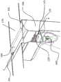
图2示意性地图示了该设备的部件的剖视图;Figure 2 schematically illustrates a cross-sectional view of the components of the apparatus;
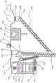
图3示意性地图示了该设备的部件的另一个剖视图;Figure 3 schematically illustrates another cross-sectional view of the components of the apparatus;
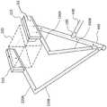
图4示意性地图示了该设备的部件的剖视图;Figure 4 schematically illustrates a cross-sectional view of the components of the apparatus;
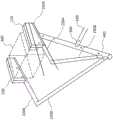
图5示意性地图示了该设备的部件的另一个剖视图;Figure 5 schematically illustrates another cross-sectional view of the components of the apparatus;
图6示意性图示了本发明的另一个实施例。Figure 6 schematically illustrates another embodiment of the present invention.
图7示意性地图示了搅拌器的实施例。Figure 7 schematically illustrates an embodiment of an agitator.
图8和图9示意性地图示了设备的改进布置,以使得原始粉末和再循环粉末能够被结合;Figures 8 and 9 schematically illustrate a modified arrangement of equipment to enable virgin powder and recycled powder to be combined;
图10和图11示意性地图示了返回槽/料斗的改进构造(作为示例,应用于图8和图9的设备);Figures 10 and 11 schematically illustrate a modified configuration of the return chute/hopper (as an example, applied to the apparatus of Figures 8 and 9);
图12和图13示意性地图示了传感器的可能位置(作为示例,应用于图8和图9的设备);Figures 12 and 13 schematically illustrate possible positions of sensors (as an example, applied to the devices of Figures 8 and 9);
图14和图15示意性地图示了设备内可能的冷却装置(例如,应用于图8和图9的设备);Figures 14 and 15 schematically illustrate possible cooling arrangements within a device (eg as applied to the devices of Figures 8 and 9);
图16示意性地图示了粉末出口孔和相关旁通阀的可能位置(作为示例,应用于图8和图9的设备);Figure 16 schematically illustrates possible positions of the powder outlet orifice and associated bypass valve (as an example applied to the apparatus of Figures 8 and 9);
图17示意性地图示了本设备的一个示例,在该示例中,在再循环过程中,过量的粉末沿着深而陡的落差下降;Figure 17 schematically illustrates an example of the apparatus in which excess powder falls along a deep and steep drop during recirculation;
图18示意性地图示了图17的设备的改进版本,以降低再循环过程中过量的粉末下降的落差深度;Figure 18 schematically illustrates a modified version of the apparatus of Figure 17 to reduce the drop depth at which excess powder falls during recirculation;
图19(相对于图18)显示了再循环管的上部部分相对于水平线的缓角度;和Figure 19 (relative to Figure 18) shows the gentle angle of the upper portion of the recirculation tube relative to the horizontal; and
图20和图21(相对于图18)显示了过量的粉末落入再循环管的上部部分所通过的最大距离。Figures 20 and 21 (relative to Figure 18) show the maximum distance over which excess powder falls into the upper part of the recirculation tube.
详细描述Detailed Description
以下公开描述了一种用于由粉末制造三维物体的设备的粉末再循环系统。该粉末再循环系统包括:输送路径,该输送路径联接到粉末罐的出口,该粉末罐被配置为储存粉末;粉末储存库(powder repository),该粉末储存库联接到输送路径的出口,该输送路径包括用于将粉末从粉末罐输送到粉末储存库的输送机构;和粉末再循环路径,该粉末再循环路径联接到粉末储存库的出口,其中该粉末再循环路径被配置为将来自粉末储存库的第一过量的粉末在粉末罐的出口上游的位置处返回到输送路径。The following disclosure describes a powder recycling system for an apparatus for manufacturing three-dimensional objects from powder. The powder recirculation system includes: a delivery path coupled to an outlet of a powder tank configured to store powder; a powder repository coupled to the outlet of the delivery path, the transport The path includes a conveying mechanism for conveying powder from the powder tank to the powder repository; and a powder recirculation path coupled to an outlet of the powder repository, wherein the powder recirculation path is configured to transfer powder from the powder repository The first excess powder of the reservoir is returned to the delivery path at a location upstream of the outlet of the powder tank.
以下公开还描述了一种用于由粉末制造三维物体的设备的粉末再循环系统。该粉末再循环系统包括:输送路径,该输送路径联接到粉末罐的出口,该粉末罐被配置为储存粉末;粉末储存库,该粉末储存库联接到输送路径的出口,该输送路径包括用于将粉末从粉末罐输送到粉末储存库的输送机构;定量给料叶片(dosing blade),该定量给料叶片用于将粉末从粉末储存库转移到包括构建区域的工作表面;用于将提供到工作表面的粉末分布到整个构建区域的装置;和粉末返回路径,该粉末返回路径被配置为在粉末分布到整个构建区域之后接收过量的粉末,并且还被配置为将过量的粉末在粉末罐的出口下方的位置处返回到输送路径。The following disclosure also describes a powder recycling system for an apparatus for making three-dimensional objects from powder. The powder recirculation system includes: a delivery path coupled to an outlet of a powder tank configured to store powder; and a powder storage reservoir coupled to the outlet of the delivery path, the delivery path including for a conveying mechanism for transporting powder from a powder tank to a powder storage depot; a dosing blade for transferring powder from the powder storage depot to a work surface including a build area; means for distributing the powder of the work surface throughout the build area; and a powder return path configured to receive excess powder after the powder has been distributed throughout the build area and also configured to distribute the excess powder in the powder tank Return to the conveying path at a location below the exit.
以下公开还描述了一种用于由构建粉末制造三维物体的设备。The following disclosure also describes an apparatus for making three-dimensional objects from building powders.
现在将详细参考实施例,其示例在附图中被图示。在下面的详细描述中,通过示例的方式阐述了许多具体细节,以便提供对相关教导的透彻理解。然而,对本领域的普通技术人员将明显的是,可以在没有这些具体细节的情况下实践本教导。Reference will now be made in detail to the embodiments, examples of which are illustrated in the accompanying drawings. In the following detailed description, numerous specific details are set forth by way of example in order to provide a thorough understanding of the related teachings. However, it will be apparent to one of ordinary skill in the art that the present teachings may be practiced without these specific details.
图1示意性地图示了用于制造三维物体的设备1,其使用高速烧结(HSS)作为一种方法来由粉末基材料创建三维物体。设备1由构建粉末制作三维物体。构建粉末可以是或可以包括热塑性聚合物材料,例如PA11、PA12、PA6、聚丙烯(PP)、聚氨酯或其他聚合物。一些金属或陶瓷也可以与设备相容,这取决于设备的辐射源可达到的烧结温度以及金属或陶瓷粉末是否不吸收特定的波长。Figure 1 schematically illustrates an
设备1包括用于储存构建粉末的容纳罐410。构建粉末根据需要沉积在容纳罐410中。根据一个实施例,新鲜的“原始”粉末沉积在容纳罐410中。新鲜的粉末被认为是之前没有在设备1中使用过的粉末。如稍后更详细讨论的,根据另一个实施例,在设备1的循环期间未被烧结的过量的粉末可以返回到容纳罐410并与原始粉末混合。当粉状材料层沉积在构建区域中时,认为设备1的循环开始。然后将辐射吸收材料(RAM)打印在粉状材料层上,并将整个构建区域暴露于辐射源以烧结粉末。烧结后,构建区域降低,这被视为是循环的结束。当另一层粉状材料沉积在构建区域中时,可视为设备的下一个循环已经开始。
设备1还包括布置在轨道450上的轴承(bearings)480上的粉末分布滑橇(powderdistribution sled)300和打印滑橇350。轨道450将滑橇300、350悬置在设备1的工作表面170上方。工作表面170包括设置在构建腔室200的顶部的构建区域190。顶置的加热器460,例如陶瓷灯,可以设置在构建区域190上方,并且返回槽210可以设置在构建区域190的一侧,如图1所示。The
如本领域所知,构建粉末可能变得紧密,并因此抑制粉末从容纳罐410中流出。为了防止这种情况,容纳罐410可以设置有搅动装置420,以保持粉末自由流动。任何搅动机构都可以用来保持粉末自由流动。根据一个实施例,粉末可以在引入到容纳罐410之后被连续搅动。根据另一个实施例,粉末可以在引入到容纳罐410之后被周期性地搅动As is known in the art, the build powder may become compact and thus inhibit powder flow from the
图2示意性地图示了设备1的部件的剖视图;粉末通过入口426进入容纳罐410,并通过出口428离开容纳罐410。在经出口428从容纳罐410出来后,粉末进入供应管430。出口428可以位于容纳罐410的底部,或者可以位于容纳罐410的壁上。图2示出了出口428位于容纳罐410的壁上、在容纳罐410的底板上方。就这个位置而言,可能需要在罐410内使用搅动装置,以确保出口428下方的粉末被使用。FIG. 2 schematically illustrates a cross-sectional view of the components of the
粉末通过出口428流入供应管430。供应管430可以包括布置在供应管430内的搅拌器,该搅拌器帮助粉末沿着供应管430自由流动到输送管440。供应管430可以以一定角度布置,使得粉末可以通过重力流动。搅拌器将在下文参照图6更详细地描述。粉末然后在入口100处进入输送管440。The powder flows into
输送管440包括布置在输送管440内的输送机构,该输送机构帮助粉末沿着输送管440移动到粉末储存库115的入口101。根据一个实施例,输送机构包括设置在输送管440内的螺旋推运螺杆(auger screw)445,该螺旋推运螺杆445至少在输送管440的大部分长度内延伸。螺旋推运螺杆的直径略小于输送管440的内径,使得螺旋推运螺杆445能够在输送管440内旋转。如现有技术中已知的,螺旋推运螺杆445包括螺旋叶片,该螺旋叶片当在输送管440内旋转时沿着旋转轴线的方向运输粉末。螺旋推运螺杆445可被布置成通过沿着旋转轴线在粉末上施加力而将粉末从入口100沿着输送管440朝向粉末储存库115的入口101运输。根据一个实施例,输送管440可以布置成与竖直方向成一定角度,使得输送管440相对于重力方向向上成一定角度。The
根据一个实施例,如图2和图4所示,供应管430在入口100处连接到输送管440,入口100位于沿着输送管440和螺旋推运螺杆445的长度的中途。例如,供应管430可以在比螺旋推运螺杆445的中部更靠近螺旋推运螺杆445的下游端(相对于粉末输送方向)的位置处连接到输送管440。容纳罐410、供应管430和输送管440的上述布置使得容纳罐410能够被包含在设备1的工作台水平面170下方,最小化了将粉末运输到达工作台水平面170所需的竖直高度,并且在供应管430与输送管440的连接点100下方提供了空间,在该空间处其他管(粉末流动路径)可以连接到输送管440。According to one embodiment, as shown in FIGS. 2 and 4 , the
当容纳罐410未被加热时,供应管430可以通过供应管430和输送管440之间的隔热件(insulation)与输送管440热分离。When the
如图3和图4所示,输送管440在入口101处连接到基本上水平的粉末储存库115,粉末储存库115例如可以采用长形槽式的整体形状。螺旋推运螺杆445将粉末沿着输送管440经由入口101运输到储存库115中。入口101充当供给点,将粉末供给到储存库115中。尽管图3和图4图示了输送管440连接到储存库115的一端,但是输送管440可以连接在沿着储存库115的任何位置,例如,在储存库115的一端处或其附近、或者沿着储存库115长度的大约一半处。根据另一个实施例,可以提供多于一个的输送管440和入口101,使得粉末从多个入口101运输到储存库115中。As shown in Figures 3 and 4, the
搅拌器110可以设置在粉末储存库115内。搅拌器110在粉末储存库115内的运动保持粉末处于自由流动或接近自由流动的状态,从而防止粉末结块,并允许粉末通过重力沿着搅拌器的长度分布开。搅拌器110不会通过沿着储存库115的长度在粉末上施加显著的分力而沿着储存库115推动粉末,且因此粉末不会被压紧。已经发现,当在粉末储存库115中设置螺旋推运螺杆时,螺旋推运螺杆由于沿着旋转轴线在粉末上施加显著的分力而压紧粉末,这也将粉末沿着连接到输送管440的储存库115移动到储存库115的一端。压实抑制了粉末的自由流动,这是不期望的。因此,可以在粉末储存库中设置搅拌器110,该搅拌器110被布置成与包括了螺旋推运螺杆445的输送管440非常接近或者作为输送管440的组合部分。搅拌器110搅拌储存库115中的粉末,并防止粉末在被输送到工作表面170上之前结块。The
图7图示了示例性搅拌器110。搅拌器110可以跨越粉末储存库115的长度并且尺寸被设计成能够在不接触储存库115的壁的情况下在储存库115内旋转。FIG. 7 illustrates an
图7的搅拌器110包括安装在轴135上的多个突起122。突起122从轴135向外延伸。如图7所示,每个叶片122的形状基本上是矩形的,然而,突起122的形状不限于基本上是矩形的。每个突起122具有形成在突起122内的空腔132。此外,在相邻突起122之间的间隙中产生空腔133。The
多个突起122沿着轴交替地沿相反的方向从轴135向外突出。根据图7,多个突起122形成为联接到轴135的单个件。图7图示了二十三个突起122,然而,根据轴135的长度,可以根据需要提供任意数量的突起122。The plurality of
图7所示的突起122没有在储存库115内的粉末上施加轴向方向上(沿着旋转轴线B)的力。由于旋转搅拌器,粉末沿着储存库分布开。此外,图7所示的搅拌器110包括空腔132、133,当搅拌器110在储存库115内完全或部分旋转时,空腔132、133使得粉末能够围绕搅拌器110流动。The
如图2至图5所示,储存库115包括出口102,使得当粉末在储存库115内的达到特定水平时,粉末流过出口102并被重新引入输送管440中。来自出口102的粉末沿着再循环管150行进。再循环管150可以布置成使得粉末通过重力进入再循环管150并沿再循环管150行进。As shown in FIGS. 2-5 , the
根据图5所示的实施例,再循环管150可以在供应管430上游的点处连接到输送管440,使得再循环的、未被使用的粉末在入口103处进入输送管440,并通过螺旋推运螺杆445沿着输送管440运输。当螺旋推运螺杆445具有从供应管430接收更多粉末的能力时,来自供应管430的粉末可以与输送管440中的再循环粉末混合。According to the embodiment shown in FIG. 5 , the
根据一个实施例,如图2所示,再循环管150可以包括搅拌器110,例如如上参考图7所述,搅拌器110布置在再循环管150的部分长度或全部长度上,以确保粉末在重力的帮助下沿着再循环管150自由流动。According to one embodiment, as shown in FIG. 2 , the
再循环管150可以是绝热的。可选地,在输送管440被加热的情况下,再循环管150也可能被加热,优选地加热到与输送管440相同的温度,在这种情况下,粉末材料可以耐受升高的温度而不退化。The
现在回到图2至图4,将描述粉末到工作表面170上的输送。该设备包括设置在储存库115的顶部处或顶部附近的定量给料叶片160。定量给料叶片160能够围绕旋转轴线旋转,该旋转轴线是沿着储存库115的长度方向延伸并穿过中心突出的枢转轴165的轴线。定量给料叶片160设置在搅拌器110上方。Returning now to Figures 2-4, the delivery of powder onto the
当定量给料叶片160旋转180度时,其沿着储存库115的顶表面的长度将堆积在储存库115顶部附近的粉末推送到工作表面170上,以在工作表面170上形成粉末堆。When the
然后,粉末通过辊子320在整个工作表面170上铺展开,辊子320布置在粉末分布滑橇300上,下面将进一步详细讨论。辊子320推动粉末穿过工作表面170,以一薄层粉末覆盖构建区域190。粉末层的厚度由构建腔室200的底板205相对于前一粉末层的顶面降低的距离决定。The powder is then spread over the
待制造的三维物体500在构建腔室200的构建区域190内形成。一薄层粉末铺展在整个工作表面170上。如下文详细讨论的,将吸收剂打印到上面并烧结,之后将构建腔室200的底板205在构建腔室200内降低,并将下一层粉末铺展到打印粉末床上。粉末层通过连续的铺展/打印/烧结步骤来构建,对于每个步骤,构建腔室200的底板205在构建腔室200内降低每个步骤的层的厚度。The three-
在辊子320的行进结束时,任何未用于覆盖构建区域190的过量的粉末可被回收以供进一步使用。图2和图4图示了返回槽210,返回槽210在构建区域190的与定量给料叶片160相反的一侧设置到工作表面170。返回槽210可以被布置成接收过量的粉末,这些过量的粉末被辊子320推送到返回槽210中。根据一个实施例,如图2所示,过滤器或网230可以设置在返回槽210中,以防止不想要的物体进入设备1。不想要的物体的示例为大的结块、从烧结/打印模型破裂掉的部分或类似的不想要的物体。如果这种不想要的物体进入设备1,它可能导致粉末供给管440、115、220A或220B的堵塞,可能损坏当前构建物并有可能损坏设备1。At the end of the travel of the
为了在构建区域190中沉积一层粉末,设备1可以测量或不测量待由定量给料叶片沉积在工作表面上的粉末量。In order to deposit a layer of powder in the
代替的是,定量给料叶片为每个层沉积步骤提供大致相同的量,该量比新粉末层所需的粉末多,并且不需要的过量的粉末被推送到返回槽210中。通过在工作表面提供过量的粉末,可以实现粉末在整个构建区域的均匀分布。Instead, the dosing blade provides approximately the same amount of powder for each layer deposition step, which is more powder than is required for a new powder layer, and the unwanted excess powder is pushed into the
返回槽210联接到返回管220。返回管220可以包括两个管,即上返回管220A和下返回管220B。返回槽210可以包含搅拌器110,以便将粉末维持在自由流动状态。The
过量的粉末沿着返回管220行进。返回管220可以布置成使得过量的粉末基本上通过重力沿着返回管220行进。The excess powder travels along
如图5所示,返回管220(下返回管220B)可以在供应管430的上游的点处连接到输送管440,使得过量的粉末在入口104处进入输送管440,并通过螺旋推运螺杆445沿着输送管440运输。当螺旋推运螺杆445具有从供应管430接收更多粉末的能力时,来自供应管430的粉末可以与输送管440中的过量的粉末混合。过量的粉末行进返回储存库115。因此,未使用的过量的粉末通过返回管220再循环到输送管440中。根据一个实施例,搅拌器110可以设置在返回管220的全部或部分长度上,以确保粉末沿着管220自由流动。As shown in FIG. 5 , return pipe 220 (
返回管220可以是绝热的。在输送管440被加热的情况下,返回管220也可能被加热,优选地加热到与输送管440相同的温度,在这种情况下,粉末材料可以在升高的温度下被保持而不会明显的退化。
如图2所示,返回管220可以连接到再循环管150,使得过量的粉末和再循环的粉末被组合并在相同的入口进入输送管440。连接返回管220和再循环管150可能是有益的,以便减少进入输送管440的入口点。此外,通过在进入输送管440之前将过量的粉末和再循环的粉末组合,过量的粉末和再循环的粉末被给予重新引入输送管440的相同的优先级。As shown in FIG. 2, the
可选地,返回管220可以在入口104处连接到输送管440,入口104在供应管430的入口100的上游并且例如还在再循环管150的入口103的上游。这使得来自返回管220的粉末优先于来自再循环管150的粉末且优先于来自再循环管150的粉末使用。这种布置在图6中示出。然而,优先顺序不限于图6所示的布置,并且存在改变优先顺序的不同组合。Optionally,
应当理解,对供应管430、再循环管150和返回管220的提及并不将这些管限制为具有圆柱形横截面。相反,管可以具有任何合适的横截面,例如半圆形、椭圆形或矩形横截面等。It should be understood that references to supply
此外,粉末储存库115、供应管430、再循环管150和返回管220都可以被视为用于粉末的流动路径。此外,粉末储存库115、供应管430、再循环管150和/或返回管220可以包括搅拌器,以便在沿着这些粉末流动路径行进时保持粉末处于自由流动状态。可选地,供应管430、再循环管150和返回管220可以不包括搅拌器。Additionally, the
现在转向对粉末分布滑橇300和打印滑橇350的操作,图1图示了设置在设备1的工作表面170上方的两个可独立操作的滑橇300、350。粉末分布滑橇300包括辊子320,并且打印滑橇350包括烧结源360(例如烧结灯)和打印头370。粉末分布滑橇300还可以包括预热源310。Turning now to the operation of the
预热源310和烧结源360是红外辐射源,其可以包括卤素灯(或者是模块化源或者是全宽单灯泡(full width single bulb)的形式);红外辐射(IR)发光二极管(LED)阵列;陶瓷灯;氩气灯;或者任何其他合适的红外辐射发射器。The preheat source 310 and the sintering source 360 are sources of infrared radiation, which may include halogen lamps (either in the form of a modular source or a full width single bulb); infrared radiation (IR) light emitting diodes (LEDs) arrays; ceramic lamps; argon lamps; or any other suitable emitter of infrared radiation.
用于沉积RAM的一个或更多个打印头370可以是适于在HSS设备中使用的标准的按需喷墨打印头(drop on demand printhead),例如Xaar 1003打印头。例如,Xaar 1003打印头能够沉积悬浮在各种液体中或可溶于各种液体中的RAM,并且由于其高效的墨水再循环技术,能够很好地耐受住HSS打印机的热及微粒环境的挑战。The one or more printheads 370 used to deposit RAM may be standard drop on demand printheads suitable for use in HSS equipment, such as Xaar 1003 printheads. For example, the Xaar 1003 printhead is capable of depositing RAM suspended or soluble in a variety of liquids and, thanks to its efficient ink recirculation technology, is well equipped to withstand the heat and particulate environments of HSS printers challenge.
回到图1,滑橇300、350可以通过设置在每个滑橇300、350上的马达移动穿过设备1的工作表面170,每个滑橇300、350可以使用相同的驱动带或不同的驱动带,尽管如本领域已知的,可以使用其他方法移动滑橇。根据一个实施例,两个滑橇300、350可在同一组轨道上移动。根据另一个实施例,两个滑橇300、350可在单独的轨道上移动。Returning to Figure 1, the
在定量给料叶片160旋转以在工作表面170上沉积粉末堆之后,粉末分布滑橇300行进穿过定量给料叶片160,并且辊子320推动粉末穿过设备的工作表面170。粉末堆通过辊子320铺展在整个工作表面170上,使得粉末层覆盖构建区域190,并且任何过量的粉末被推下至返回槽210。当粉末分布滑橇300还包括预热源310时,随着粉末层由辊子320铺展在整个构建区域190上,粉末层被预热灯310加热。然而,当粉末分布滑橇300不包括预热源310时,可以在构建区域190上方提供顶置热源。可选地,如果需要,设置在打印滑橇350上的烧结源可以用作预热源。After the
然后,打印滑橇350移动穿过设备的工作表面170,并且根据限定正构建的最终物体的每一层的图案的图像数据,通过打印头370将诸如辐射吸收材料(RAM)的吸收剂打印到构建区域190内的粉末层上。然后,当烧结灯360移动穿过整个构建区域190时,构建区域190中的粉末层的打印的部分被烧结,其效果为只有接收了吸收剂的粉末被充分加热以熔合。The
构建腔室200的底板205在构建腔室200内降低,并且下一层粉末通过辊子320铺展在整个工作表面170上,并且该过程再次开始。构建腔室底板205被降低构建物的层的厚度,这可能在0.1mm的范围内。The
为了便于进入构建区域190,轨道450可以彼此竖直偏离。例如,机器前部的轨道可以低于工作台170的水平高度,以允许容易地接近构建腔室200,而后部的轨道可以高于工作台的高度,以允许接近对轨道进行维护或清洁。To facilitate access to build
滑橇300、350相对于构建区域190的位置可以由设置在每个滑橇300、350上的位置传感器监控。位置传感器可以是安装在机器的静态部分上的带有标尺的磁传感器、旋转编码器、安装在机器的静态部分上的带有标尺的光学传感器、激光定位器等。The position of the
如本领域所知,高速烧结机器在高温下运行,特别是在构建区域190附近。例如,构建区域附近的温度可能在185℃左右。因此,机器的温度敏感元件,例如打印头370,可能需要屏蔽热。可以在打印头周围提供绝缘壳体以提供这种屏蔽。As is known in the art, high-speed sintering machines operate at high temperatures, particularly around
顶置加热器460可以设置在构建区域上方,以在构建区域190的表面上提供均匀的温度。顶置加热器460可以是任何固定的红外辐射源,例如陶瓷IR灯或任何其他合适的辐射源。An
根据一个实施例,轴承可设置在每个滑橇300、350的一侧,轴承可垂直于滑橇300、350的移动方向移动,以允许滑橇300、350随着温度变化而膨胀或收缩。According to one embodiment, a bearing may be provided on one side of each
众所周知,为了获得均匀的构建区域温度,在开始构建之前,在构建腔室底板205上沉积几个粉末缓冲层是有益的,以有助于减轻在整个构建区域190的表面上温度分布不均匀的影响。这可以在构建腔室底板205的底部被加热之外进行。As is well known, in order to obtain a uniform build area temperature, it is beneficial to deposit several powder buffer layers on the
缓冲层可以具有或可以不具有与构建物的层相同的厚度。当缓冲层的厚度与构建物的层的厚度不相同时,则最终缓冲层中的一个或更多个可以以构建物的层的厚度铺设。例如,构建物的层的厚度可以是0.1mm。该厚度可以通过将构建腔室的底板205降低0.1mm来实现。The buffer layer may or may not have the same thickness as the layers of the construct. When the thickness of the buffer layer is not the same as the thickness of the layers of the construct, then one or more of the final buffer layers may be laid down at the thickness of the layers of the construct. For example, the thickness of the layers of the construct may be 0.1 mm. This thickness can be achieved by lowering the
可以提供打印头清洁站。打印头清洁站可以位于工作台的与定量给料叶片160相反的一端。一旦打印滑橇350已经到达行程的终点,打印头370可以在下一个行程之前被清洁。打印头370可以在每个行程之后、每个设定的行程次数之后或者响应于打印头喷嘴监控系统而被清洁。A printhead cleaning station is available. The printhead cleaning station may be located at the opposite end of the table from the
应当理解,尽管为了说明所描述的发明如何可以用于形成三维物体的设备中而描述了高速烧结打印机设备和工艺,但是本发明同样可以与需要将粉末输送到工作表面的制造三维物体的不同的设备和工艺结合使用。这可以例如包括使用各种粉末材料的激光烧结、打印和粘合或电子束设备和工艺。It should be understood that although the high speed sintering printer apparatus and process are described in order to illustrate how the described invention may be used in an apparatus for forming three-dimensional objects, the present invention may also differ from those for making three-dimensional objects that require the delivery of powder to a work surface. Equipment and process are used in combination. This may include, for example, laser sintering, printing and bonding or electron beam equipment and processes using various powder materials.
可能的修改和替代实施例Possible Modifications and Alternative Embodiments
上面已经描述了详细的实施例,以及一些可能的修改和替代。对于本领域技术人员将清楚的是,在不脱离本技术的范围的情况下可以对前述示例性实施例进行许多改进和额外的修改和替代。现在将描述一些特定的改进,如下:Detailed embodiments have been described above, along with some possible modifications and alternatives. It will be apparent to those skilled in the art that many modifications and additional modifications and substitutions can be made to the foregoing exemplary embodiments without departing from the scope of the present technology. Some specific improvements will now be described as follows:
原始供给修改(图8和图9)Original Supply Modifications (Figures 8 and 9)
如图8和图9所示,供应管430可以连接到再循环管150,使得原始粉末和再循环的粉末混合并在相同的入口处进入输送管440。这可能是有益的,以便将进入输送管440的入口点最小化。As shown in FIGS. 8 and 9 , the
此外,如果系统不是空的并且不需要添加粉末,则这种构造最大限度地减小了粉末向系统的供给。在供应管430直接供给到输送管440中的先前配置中,已发现,供应管430可能会继续将粉末添加到系统中,即使系统已经尽可能的满了,这将导致粉末的过度累积和操作故障的发生。可认为,这是由于当螺旋推运螺杆445旋转时,粉末被供给到螺旋推运螺杆445的叶片背面的小空隙(空气空腔)中,从而使已经充满的系统过载。然而,通过供应管430向再循环管150供给,供应管搅拌器可以与再循环搅拌器在不同的时间运行,或者再循环搅拌器可以非常缓慢地运行,从而确保没有空腔。通过将再循环管150定向成接近竖直,可以缓慢地运行再循环搅拌器,从而只需要很少的搅拌来推动粉末。因此,当系统需要时,这种配置可以仅从供应管430中获取原始粉末,从而使系统自我调节。Furthermore, this configuration minimizes the supply of powder to the system if the system is not empty and no powder needs to be added. In previous configurations where the
供应管430可以具有15°的倾斜(fall)。这允许粉末更好地从供应管430供给到再循环管150中。The
返回管220(下返回管220B)可以在再循环管150的上游点处连接到输送管440。这使得来自返回管220的粉末优先于来自再循环管150的粉末且优先于来自供应管430的粉末使用。这种布置是有利的,因为返回管220中的回收粉末已经暴露在比原始粉末或再循环粉末(再循环粉末已经暴露在比原始粉末更高的温度下)更高的温度下,且因此可以首先使用返回管220中的回收粉末,而不是原始粉末或再循环粉末。以这种方式,可以提高粉末的再利用性。Return pipe 220 (
料斗形返回槽(图10和图11)Hopper-shaped return chute (Figure 10 and Figure 11)
如图10和图11所示,返回槽210可以具有加宽的开口,使得过量的粉末不会沉积到工作表面170的远侧。此外,返回槽210可以具有一个或更多个倾斜侧面211(即,形如料斗),使得过量的粉末可以以受控的速率容易地收集到返回槽210中,该受控的速率减少或防止飘浮颗粒(airborne particles)的产生。粉末可以简单地通过重力供给到返回管220。此外,在返回管220A的入口处可以有利地避免粉末压紧或堵塞。As shown in FIGS. 10 and 11 , the
此外,可能有一种可能性,粉末颗粒粘附到返回槽210的表面。因此,返回槽210可以被布置成具有振动表面或振动网,或者用于向返回槽210提供振动的替代装置。这种振动表面可以例如代替料斗形状的倾斜侧面211中的一个。用于提供振动的装置可以包括超声波换能器或压电换能器或旋转马达,但不限于此。Furthermore, there may be a possibility that powder particles adhere to the surface of the
传感器(图12和图13)Sensor (Figure 12 and Figure 13)
不同的粉末参数可以使用一个或更多个传感器来测量或检测。例如,参数可以包括粉末的水平高度、粉末的温度等。对用于制造三维物体的设备中的参数进行控制是重要的,因为参数可以在不同的位置或点变化。因此,对粉末再循环系统中的不同的点处的参数进行测量可能有利于检测故障,并且也有利于有效地控制系统。Different powder parameters can be measured or detected using one or more sensors. For example, parameters may include the level of the powder, the temperature of the powder, and the like. It is important to control the parameters in the equipment used to manufacture the three-dimensional objects because the parameters can vary at different locations or points. Therefore, measuring parameters at various points in the powder recirculation system may be useful for detecting faults and also for effectively controlling the system.
由于再循环管150包括来自不同来源的粉末,在再循环管150上的不同点处提供一个或更多个传感器可能是有利的。至少一个传感器(未示出)可以布置在再循环管150的出口的下游或附近,并且可以在该点处测量粉末参数。可选地或附加地,如图12所示,至少一个传感器S1可以靠近供应管430的连接点设置在再循环管150上。利用该传感器,可以在连接点处检测粉末参数,例如温度。此外,至少一个传感器(未示出)可以设置在再循环管150的入口附近,以便测量从粉末储存库115进入再循环管150的粉末的参数。Since the
还可以在返回管220上设置一个或更多个传感器S2。此外,返回槽/料斗210可以具有一个或更多个传感器S3,以便测量其参数,例如,粉末水平和/或所接收的过量的粉末的温度。One or more sensors S2 may also be provided on the
类似地,如图13所示,粉末储存库115可以具有一个或更多个传感器S3、S4,以检测储存库115中粉末的粉末水平和/或温度。Similarly, as shown in FIG. 13 , the
在上述位置使用的传感器的类型不必全部相同,且不同类型的传感器可以在不同的位置使用。图12显示了粉末再循环系统中传感器的不同位置。然而,本发明不限于这些位置,并且不同类型的一个或更多个传感器可以设置在所需的位置,使得它们可靠地检测所需的参数。The types of sensors used in the above locations need not all be the same, and different types of sensors may be used in different locations. Figure 12 shows the different positions of the sensors in the powder recirculation system. However, the present invention is not limited to these locations, and one or more sensors of different types can be placed at the desired locations so that they reliably detect the desired parameters.
每个传感器可以是二进制、数字或模拟传感器。传感器的类型不受限制。可以使用本领域中通常已知的任何类型的用于检测粉末参数的传感器,例如光学传感器、电容传感器、热响应传感器、旋转传感器、传导/感应传感器等。Each sensor can be a binary, digital or analog sensor. The type of sensor is not limited. Any type of sensor generally known in the art for detecting powder parameters may be used, such as optical sensors, capacitive sensors, thermally responsive sensors, rotational sensors, conductive/inductive sensors, and the like.
粉末再循环系统可以进一步包括控制器。各种传感器的输出可以被供给到控制器,并且控制器可以基于从各种传感器接收的反馈来控制对系统的操作。例如,如果粉末储存库115中的所测量的粉末水平高于预定阈值水平,则控制器可以停止对螺旋推运螺杆445的操作,或者根据粉末水平可以降低螺旋推运螺杆445的速度。可选地,控制器可以通过发送信号或在显示面板上显示警告来提醒用户,且因此用户可以采取适当的行动。The powder recirculation system may further include a controller. The outputs of the various sensors can be supplied to the controller, and the controller can control the operation of the system based on feedback received from the various sensors. For example, if the measured powder level in
类似地,如果返回槽/料斗210中测量的粉末水平高于预定阈值,则控制器可以完全停止系统或者可以控制定量给料叶片160以输送更少的粉末。可选地,控制器可以提醒用户,以便用户可以取出过量的粉末。Similarly, if the measured powder level in the return chute/
基于对温度的反馈,并且在将温度与预定阈值水平进行比较之后,控制器可以完全或部分地关闭系统,或者可以通过减慢系统来控制系统的操作。控制器也可以启动冷却系统(例如,如下面关于图14和图15所讨论的)。Based on feedback on the temperature, and after comparing the temperature to a predetermined threshold level, the controller may shut down the system completely or partially, or may control the operation of the system by slowing the system. The controller may also activate the cooling system (eg, as discussed below with respect to Figures 14 and 15).
阈值水平的值可以预先存储在控制器的存储器中,或者可以由用户输入,并且然后存储在控制器的存储器中。The value of the threshold level may be pre-stored in the memory of the controller, or may be entered by the user and then stored in the memory of the controller.
冷却回路(图14和图15)Cooling circuit (Figure 14 and Figure 15)
如图14和图15所示,返回管220(下返回管220B)可以设置有冷却装置C1,C2,以便将返回管220中的粉末温度保持在预定的阈值水平内。冷却可以是主动冷却或被动冷却。可以使用任何类型的冷却装置。例如,如图14所示,可以在返回管220的外围设置散热片C1,或者如图15所示,可以在返回管220周围缠绕冷却套C2。然而,冷却装置的类型不限于这些。冷却装置可以由控制器控制,控制器从一个或更多个温度传感器接收输入。控制器可以被配置为仅当感测到的温度超过预定温度水平时才启动冷却装置。As shown in Figures 14 and 15, the return pipe 220 (
用于粉末移除的出口(图16)Outlet for powder removal (Fig. 16)
一旦三维物体(或其一部分)已经形成,用户可能想要为下一个物体使用不同类型的粉末;或者可能想要使用不同类型的粉末来形成三维物体的不同部分。在这种情况下,可能需要从系统中移除现有粉末。因此,如图16所示,在粉末再循环系统的最低点或螺旋推运螺杆445的上游设置用于移除粉末的出口孔(例如,槽或其他开口)以及用于移开孔的遮盖物的装置V1、V2(例如,阀或致动器操作开关或滑动机构)是有利的。粉末可能由于重力而流动,或者可以使用吸力来移除粉末。通过这种方式,大部分粉末可以从系统中移除,并且可以收集在系统外部的容器中。Once the three-dimensional object (or part thereof) has been formed, the user may want to use a different type of powder for the next object; or may want to use a different type of powder to form different parts of the three-dimensional object. In this case, existing powder may need to be removed from the system. Therefore, as shown in Figure 16, an outlet hole (eg, a slot or other opening) for removing powder and a cover for removing the hole are provided at the lowest point of the powder recirculation system or upstream of the
此外,由于多次使用,返回管中粉末的质量可能会随着时间的推移而退化,并且可能不再适合进一步使用。因此,为了从系统中移除退化的粉末,在返回管220上具有出口孔(例如,槽或其他开口)和暴露该孔的装置是有利的,退化的粉末可以通过该出口孔从系统中移除。该装置可以是旁通阀B2、或致动器操作开关或滑动机构。Also, due to multiple uses, the quality of the powder in the return tube may degrade over time and may no longer be suitable for further use. Therefore, in order to remove degraded powder from the system, it is advantageous to have an outlet hole (eg, a slot or other opening) in the
再循环管道中的灰尘减少(图17-图21)Dust reduction in recirculation ducts (Figures 17-21)
首先参考图17,在本设备的开发过程中,经发现,当过量的粉末落入再循环管150时,可能会产生粉状灰尘(powdery dust)。这是由于管150的陡角度导致一些再循环粉末在进入管150时下落相当大的距离。图17中的向下箭头D1显示了这一显著的下落。当定量给料叶片160旋转时,由此产生的粉状灰尘可以释放到机器的工作表面170上方的空间/环境中。工作表面170中的灰尘易于落在运动部件和传感器上,妨碍了对操作的精确控制。此外,飘浮的灰尘会对机器操作员的健康和安全构成威胁。Referring first to Figure 17, during the development of the present apparatus, it was discovered that when excess powder falls into the
为了解决上述问题,图18图示了粉末再循环系统的改进设计,其中再循环管150被分成两个段,即缓段150A和陡段150B。这给出了较缓的初始粉末下落,如向下箭头D2所示,使得产生明显较少的粉状灰尘。与图3中所示的相比,管的这种几何形状还使得定量给料叶片160能够在另一方向上旋转,其中溢出处位于粉末储存库115的另一侧。In order to solve the above problems, FIG. 18 illustrates an improved design of the powder recirculation system, in which the
应当注意,在图17和图18之间,粉末储存库115和再循环管150变换了它们的位置。利用这种构造,当定量给料叶片160旋转时,再循环管150中产生的任何灰尘都不会到达工作表面170上。It should be noted that between Figures 17 and 18, the
更详细地,缓角度段150A被布置成接收来自定量给料叶片160附近的溢出粉末(例如,通过上述出口102)。在图19中,相对于水平线H,段150A的缓倾斜角度,用X表示。该角度X缓降,意味着在用于粉末进入再循环管的任何点处都不会有长时间的下落。然后,陡角度段150B将粉末返回到输送管440。陡角度段150B离定量给料叶片160的区域足够远,使得当定量给料叶片160旋转时,产生的任何灰尘都不会进入工作表面170。In more detail, the gently
再循环管段150A和图150B都可以包含搅拌器,以确保粉末沿着它们自由流动。Both
过量的粉末从粉末储存库115的出口102落入再循环管150A的最大距离在图20和21中用“h”表示。The maximum distance that excess powder falls from
更具体地,如图20所示,“h”是粉末储存库115的出口102和再循环管的缓角度段150A的底部150A’之间的最大落差,即过量的粉末通过再循环管下降的最大落差。当设计两段式再循环管的布置时,缓段150A的角度(图19中的X)应使距离h最小,同时仍能使粉末沿管流动。More specifically, as shown in Figure 20, "h" is the maximum drop between the
图21更详细地显示了落差“h”的测量位置。如图所示,落差“h”是从过量的粉末流过的出口102的上边缘开始测量的。Figure 21 shows the measurement locations of the drop "h" in more detail. As shown, the drop "h" is measured from the upper edge of the
对再循环管150的上述改进也可以应用于返回管220。如上所述,返回管220可以包括具有缓角度的上返回管220A和具有陡角度的下返回管220B。上返回管220A的缓角度使得当粉末通过返回槽210下降时,通过减小粉末下降的落差高度而将粉状灰尘的产生最小化。The above improvements to the
结尾总结Conclusion
本文描述了一种用于由粉末制造三维物体的设备的粉末再循环系统。根据一个实施例,输送机构将第一过量的粉末从粉末再循环路径输送到粉末储存库。This paper describes a powder recycling system for an apparatus for manufacturing three-dimensional objects from powder. According to one embodiment, the delivery mechanism delivers the first excess powder from the powder recirculation path to the powder storage reservoir.
根据另一实施例,当来自粉末再循环路径的第一过量的粉末下降到预定水平以下时,输送机构从粉末罐中抽取粉末。According to another embodiment, the delivery mechanism draws powder from the powder tank when the first excess powder from the powder recirculation path falls below a predetermined level.
根据另一实施例,当不再有足够量的来自粉末再循环路径的第一过量的粉末填充输送路径时,输送机构从粉末罐中抽取粉末。According to another embodiment, the conveying mechanism draws powder from the powder tank when there is no longer a sufficient amount of first excess powder from the powder recirculation path to fill the conveying path.
根据另一实施例,输送机构将来自粉末再循环路径的第一过量的粉末与来自粉末罐的粉末混合。According to another embodiment, the delivery mechanism mixes the first excess powder from the powder recirculation path with the powder from the powder tank.
根据另一个实施例,粉末再循环路径被加热到等于输送路径温度的温度。According to another embodiment, the powder recirculation path is heated to a temperature equal to the temperature of the conveying path.
根据另一实施例,粉末再循环路径被配置为使得第一过量的粉末通过重力沿着粉末再循环路径行进。According to another embodiment, the powder recirculation path is configured such that the first excess powder travels along the powder recirculation path by gravity.
根据另一实施例,粉末再循环系统还包括:设置在粉末再循环路径中的搅拌器。According to another embodiment, the powder recirculation system further includes: an agitator disposed in the powder recirculation path.
根据另一个实施例,粉末再循环系统还包括:定量给料叶片,该定量给料叶片用于将粉末从粉末储存库转移到包括构建区域的工作表面;用于将提供给工作表面的粉末分布到整个构建区域的装置;和粉末返回路径,该粉末返回路径被配置为在粉末分布到整个构建区域之后接收第二过量的粉末,并且还被配置为将第二过量的粉末在粉末罐出口上游的位置处返回到输送路径。According to another embodiment, the powder recirculation system further comprises: a dosing blade for transferring powder from the powder storage to a work surface including a build area; for distributing the powder provided to the work surface means to the entire build area; and a powder return path configured to receive a second excess powder after the powder has been distributed throughout the build area and further configured to deliver the second excess powder upstream of the powder tank outlet position to return to the conveying path.
根据另一实施例,输送机构被配置为将第二过量的粉末从粉末返回路径输送到粉末储存库。According to another embodiment, the delivery mechanism is configured to deliver the second excess powder from the powder return path to the powder reservoir.
根据另一实施例,当来自粉末再循环路径的第一过量的粉末和来自粉末返回路径的第二过量的粉末下降到预定水平以下时,输送机构从粉末罐中抽取粉末。According to another embodiment, the delivery mechanism draws powder from the powder tank when the first excess powder from the powder recirculation path and the second excess powder from the powder return path fall below predetermined levels.
根据另一实施例,当不再有足够量的来自粉末再循环路径的第一过量的粉末或来自粉末返回路径的第二过量的粉末填充输送路径时,输送机构从粉末罐中抽取粉末。According to another embodiment, the conveying mechanism draws powder from the powder tank when a sufficient amount of either the first excess powder from the powder recirculation path or the second excess powder from the powder return path no longer fills the conveying path.
根据另一实施例,输送机构将来自粉末返回路径的第二过量的粉末与来自粉末再循环路径的第一过量的粉末混合。According to another embodiment, the conveying mechanism mixes the second excess powder from the powder return path with the first excess powder from the powder recirculation path.
根据另一实施例,输送机构将来自粉末返回路径的第二过量的粉末与来自粉末再循环路径的第一过量的粉末以及来自粉末罐的粉末混合。According to another embodiment, the conveying mechanism mixes the second excess powder from the powder return path with the first excess powder from the powder recirculation path and powder from the powder tank.
根据另一个实施例,粉末返回路径被配置为在比来自粉末再循环路径的第一过量的粉末返回到输送路径的位置低的位置处将第二过量的粉末返回到输送路径。According to another embodiment, the powder return path is configured to return the second excess powder to the delivery path at a lower position than the position at which the first excess powder from the powder recirculation path returns to the delivery path.
根据另一个实施例,粉末返回路径被配置为将第二过量的粉末与来自粉末再循环路径的第一过量的粉末在相同的位置处返回到输送路径中。According to another embodiment, the powder return path is configured to return the second excess powder into the delivery path at the same location as the first excess powder from the powder recirculation path.
根据另一个实施例,粉末再循环路径联接到粉末返回路径,使得来自粉末再循环路径的第一过量的粉末和来自粉末返回路径的第二过量的粉末在返回到输送路径之前在粉末罐出口下方的位置被组合。According to another embodiment, the powder recirculation path is coupled to the powder return path such that the first excess powder from the powder recirculation path and the second excess powder from the powder return path are below the powder tank outlet before returning to the delivery path positions are combined.
根据另一实施例,粉末再循环系统还包括:设置在粉末返回路径中的过滤器。According to another embodiment, the powder recirculation system further includes a filter disposed in the powder return path.
根据另一个实施例,粉末返回路径被加热到等于输送路径温度的温度。According to another embodiment, the powder return path is heated to a temperature equal to the transport path temperature.
根据另一实施例,粉末返回路径被配置为使得第二过量的粉末通过重力沿着粉末返回路径行进。According to another embodiment, the powder return path is configured such that the second excess powder travels along the powder return path by gravity.
根据另一实施例,粉末再循环系统还包括:设置在粉末返回路径中的搅拌器。According to another embodiment, the powder recirculation system further includes: an agitator disposed in the powder return path.
根据另一个实施例,粉末再循环系统还包括:返回槽,该返回槽在构建区域的与定量给料叶片相反的一侧设置到工作表面,该返回槽被配置为在粉末分布到整个构建区域之后接收第二过量的粉末,并且联接到粉末返回路径。According to another embodiment, the powder recirculation system further comprises: a return slot provided to the work surface on the opposite side of the build area from the dosing vanes, the return slot configured to distribute the powder throughout the build area A second excess of powder is then received and coupled to the powder return path.
根据另一个实施例,其中定量给料叶片以设定的频率将设定量的粉末转移到工作表面。According to another embodiment, wherein the dosing blade transfers a set amount of powder to the working surface at a set frequency.
根据另一实施例,输送机构被配置为将过量的粉末从粉末返回路径输送到粉末储存库。According to another embodiment, the delivery mechanism is configured to deliver excess powder from the powder return path to the powder storage reservoir.
根据另一实施例,当来自粉末返回路径的过量的粉末下降到预定水平以下时,输送机构从粉末罐中抽取粉末。According to another embodiment, the delivery mechanism draws powder from the powder tank when the excess powder from the powder return path falls below a predetermined level.
根据另一实施例,当不再有足够量的来自粉末返回路径的过量的粉末填充输送路径时,输送机构从粉末罐中抽取粉末。According to another embodiment, the delivery mechanism draws powder from the powder tank when there is no longer a sufficient amount of excess powder from the powder return path to fill the delivery path.
根据另一实施例,输送机构将来自粉末返回路径的过量的粉末与来自粉末罐的粉末混合。According to another embodiment, the delivery mechanism mixes excess powder from the powder return path with powder from the powder tank.
根据另一实施例,粉末再循环系统还包括:设置在粉末返回路径中的过滤器。According to another embodiment, the powder recirculation system further includes a filter disposed in the powder return path.
根据另一个实施例,粉末返回路径被加热到等于输送路径温度的温度。According to another embodiment, the powder return path is heated to a temperature equal to the transport path temperature.
根据另一个实施例,粉末返回路径被配置为使得过量的粉末通过重力沿着粉末返回路径行进。According to another embodiment, the powder return path is configured such that the excess powder travels along the powder return path by gravity.
根据另一实施例,粉末再循环系统还包括:设置在粉末返回路径中的搅拌器。According to another embodiment, the powder recirculation system further includes: an agitator disposed in the powder return path.
根据另一个实施例,粉末再循环系统还包括:返回槽,该返回槽在构建区域的与定量给料叶片相反的一侧设置到工作表面,该返回槽被配置为在粉末分布到整个构建区域之后接收第二过量的粉末,并且联接到粉末返回路径。According to another embodiment, the powder recirculation system further comprises: a return slot provided to the work surface on the opposite side of the build area from the dosing vanes, the return slot configured to distribute the powder throughout the build area A second excess of powder is then received and coupled to the powder return path.
根据另一个实施例,定量给料叶片以设定的频率将设定量的粉末转移到工作表面。According to another embodiment, the dosing blade transfers a set amount of powder to the working surface at a set frequency.
根据另一个实施例,输送路径被加热到预定温度。According to another embodiment, the transport path is heated to a predetermined temperature.
根据另一个实施例,粉末罐的出口与输送路径绝热。According to another embodiment, the outlet of the powder tank is thermally insulated from the conveying path.
根据另一个实施例,输送机构包括螺旋推运螺杆。According to another embodiment, the conveying mechanism includes an auger screw.
根据另一个实施例,粉末再循环路径和/或粉末返回路径包括具有缓倾斜角度的上段,用于在使用中接收落下的粉末,该上段联接到较陡的下段。According to another embodiment, the powder recirculation path and/or the powder return path includes an upper section having a gentle slope angle for receiving falling powder in use, the upper section being coupled to a steeper lower section.
Claims (39)
Applications Claiming Priority (3)
| Application Number | Priority Date | Filing Date | Title |
|---|---|---|---|
| GB1719096.8 | 2017-11-17 | ||
| GB1719096.8AGB2568521B (en) | 2017-11-17 | 2017-11-17 | Apparatus for the manufacture of three-dimensional objects |
| PCT/GB2018/053336WO2019097255A1 (en) | 2017-11-17 | 2018-11-16 | Apparatus for the manufacture of three-dimensional objects |
Publications (2)
| Publication Number | Publication Date |
|---|---|
| CN111601714Atrue CN111601714A (en) | 2020-08-28 |
| CN111601714B CN111601714B (en) | 2022-04-29 |
Family
ID=60805559
Family Applications (1)
| Application Number | Title | Priority Date | Filing Date |
|---|---|---|---|
| CN201880073479.8AActiveCN111601714B (en) | 2017-11-17 | 2018-11-16 | Apparatus for manufacturing three-dimensional objects |
Country Status (8)
| Country | Link |
|---|---|
| US (3) | US11780167B2 (en) |
| EP (1) | EP3710253B1 (en) |
| JP (1) | JP7169360B2 (en) |
| CN (1) | CN111601714B (en) |
| ES (1) | ES2936607T3 (en) |
| GB (1) | GB2568521B (en) |
| IL (1) | IL274472B2 (en) |
| WO (1) | WO2019097255A1 (en) |
Families Citing this family (16)
| Publication number | Priority date | Publication date | Assignee | Title |
|---|---|---|---|---|
| GB2579560B (en)* | 2018-12-03 | 2021-10-06 | Xaar 3D Ltd | Powder dosing system |
| US11130291B2 (en)* | 2019-03-29 | 2021-09-28 | Xerox Corporation | Composite-based additive manufacturing (CBAM) use of gravity for excess polymer removal |
| US11833587B2 (en)* | 2020-02-20 | 2023-12-05 | Layerwise Nv | Metal powder fusion manufacturing with improved quality |
| US12337541B2 (en)* | 2020-02-27 | 2025-06-24 | Divergent Technologies, Inc. | Powder bed fusion additive manufacturing system with desiccant positioned within hopper and ultrasonic transducer |
| DE102020105819A1 (en)* | 2020-03-04 | 2021-09-09 | Ald Vacuum Technologies Gmbh | Squeegee unit for an additive manufacturing system with powdered starting material |
| GB2593453B (en) | 2020-03-17 | 2024-06-05 | C4 Carbides Ltd | Powder feeder |
| JP7521301B2 (en)* | 2020-07-23 | 2024-07-24 | セイコーエプソン株式会社 | 3D modeling equipment |
| JP7521300B2 (en)* | 2020-07-23 | 2024-07-24 | セイコーエプソン株式会社 | 3D modeling equipment |
| WO2022045917A1 (en)* | 2020-08-31 | 2022-03-03 | Общество С Ограниченной Ответственностью "Аддитив Продакшн Групп" | Printing head for 3d printing with multiple materials |
| EP4232265A1 (en)* | 2020-10-21 | 2023-08-30 | General Electric Company | Material supply systems and methods for using the same |
| US20230391008A1 (en)* | 2020-10-21 | 2023-12-07 | General Electric Company | Material supply systems for additive manufacturing and methods for using the same |
| WO2022087044A1 (en) | 2020-10-21 | 2022-04-28 | General Electric Company | Material supply system and method for using the same |
| US11932494B2 (en) | 2021-05-25 | 2024-03-19 | Arcam Ab | Raw material delivery devices and methods of operating the same |
| CN113547744A (en)* | 2021-07-20 | 2021-10-26 | 南昌航空大学 | A split directional energy deposition powder feeding nozzle |
| EP4151391A1 (en)* | 2021-09-15 | 2023-03-22 | Sinterit Sp. z o.o. | A pbf printer with a powder circulation system |
| GB2626548A (en)* | 2023-01-25 | 2024-07-31 | Stratasys Powder Production Ltd | Build material supply system for apparatus for the layerwise manufacture of 3D objects and method of build material transport |
Citations (3)
| Publication number | Priority date | Publication date | Assignee | Title |
|---|---|---|---|---|
| US20010045678A1 (en)* | 2000-05-25 | 2001-11-29 | Minolta Co., Ltd. | Three-dimensional modeling apparatus |
| WO2017005301A1 (en)* | 2015-07-07 | 2017-01-12 | Hewlett-Packard Development Company L.P. | Supplying build material |
| WO2017194118A1 (en)* | 2016-05-12 | 2017-11-16 | Hewlett-Packard Development Company, L.P., | Overflow routing of non-fused build material |
Family Cites Families (20)
| Publication number | Priority date | Publication date | Assignee | Title |
|---|---|---|---|---|
| FR2166526A5 (en)* | 1971-12-28 | 1973-08-17 | Boudet Jean | Concentrated beam particle melting - at focal point of several beams |
| US20020090410A1 (en) | 2001-01-11 | 2002-07-11 | Shigeaki Tochimoto | Powder material removing apparatus and three dimensional modeling system |
| JP2002205338A (en) | 2001-01-11 | 2002-07-23 | Minolta Co Ltd | Powder material removal device and 3D modeling system |
| US20060214335A1 (en) | 2005-03-09 | 2006-09-28 | 3D Systems, Inc. | Laser sintering powder recycle system |
| CN101326046A (en)* | 2005-09-20 | 2008-12-17 | Pts软件公司 | An apparatus for building a three-dimensional article and a method for building a three-dimensional article |
| DE102007050679A1 (en) | 2007-10-21 | 2009-04-23 | Voxeljet Technology Gmbh | Method and device for conveying particulate material in the layered construction of models |
| DE102013000511A1 (en)* | 2013-01-15 | 2014-07-17 | Cl Schutzrechtsverwaltungs Gmbh | Device for producing three-dimensional objects |
| ES3007507T3 (en)* | 2013-07-31 | 2025-03-20 | Limacorporate Spa | Method for the recovery and regeneration of metal powder in ebm applications |
| GB201315036D0 (en)* | 2013-08-22 | 2013-10-02 | Renishaw Plc | Apparatus and method for building objects by selective solidification of powder material |
| US9486878B2 (en) | 2014-06-20 | 2016-11-08 | Velo3D, Inc. | Apparatuses, systems and methods for three-dimensional printing |
| FR3032637A1 (en) | 2015-02-16 | 2016-08-19 | Michelin & Cie | METHOD FOR MANAGING A POWDER IN AN ADDITIVE MANUFACTURING PLANT COMPRISING A PLURALITY OF MACHINES |
| JP6617515B2 (en) | 2015-06-12 | 2019-12-11 | 株式会社リコー | 3D modeling equipment |
| US10166718B2 (en) | 2015-06-12 | 2019-01-01 | Ricoh Company, Ltd. | Apparatus for fabricating three-dimensional object |
| US10226917B2 (en)* | 2015-07-27 | 2019-03-12 | Dmg Mori Seiki Usa | Powder delivery systems and methods for additive manufacturing apparatus |
| US10814387B2 (en) | 2015-08-03 | 2020-10-27 | General Electric Company | Powder recirculating additive manufacturing apparatus and method |
| CN108025502B (en) | 2015-09-16 | 2020-11-13 | 应用材料公司 | Powder Delivery for Additive Manufacturing |
| DE102015222689A1 (en) | 2015-11-17 | 2017-05-18 | Realizer Gmbh | Mold production device for the production of moldings by site-selective solidification of material powder |
| US10596760B2 (en) | 2015-11-23 | 2020-03-24 | Hewlett-Packard Development Company, L.P. | Supplying build material |
| US20190061254A1 (en) | 2016-04-22 | 2019-02-28 | Hewlett-Packard Development Company, L.P. | Moveable belt to carry a build material |
| JP6132962B1 (en)* | 2016-06-01 | 2017-05-24 | 株式会社ソディック | Laminate modeling apparatus and method of reusing material powder of additive modeling apparatus |
- 2017
- 2017-11-17GBGB1719096.8Apatent/GB2568521B/enactiveActive
- 2018
- 2018-11-16EPEP18808472.7Apatent/EP3710253B1/enactiveActive
- 2018-11-16WOPCT/GB2018/053336patent/WO2019097255A1/ennot_activeCeased
- 2018-11-16JPJP2020544993Apatent/JP7169360B2/enactiveActive
- 2018-11-16ESES18808472Tpatent/ES2936607T3/enactiveActive
- 2018-11-16USUS16/764,924patent/US11780167B2/enactiveActive
- 2018-11-16ILIL274472Apatent/IL274472B2/enunknown
- 2018-11-16CNCN201880073479.8Apatent/CN111601714B/enactiveActive
- 2023
- 2023-08-22USUS18/453,794patent/US12304146B2/enactiveActive
- 2025
- 2025-01-17USUS19/030,832patent/US20250242543A1/enactivePending
Patent Citations (3)
| Publication number | Priority date | Publication date | Assignee | Title |
|---|---|---|---|---|
| US20010045678A1 (en)* | 2000-05-25 | 2001-11-29 | Minolta Co., Ltd. | Three-dimensional modeling apparatus |
| WO2017005301A1 (en)* | 2015-07-07 | 2017-01-12 | Hewlett-Packard Development Company L.P. | Supplying build material |
| WO2017194118A1 (en)* | 2016-05-12 | 2017-11-16 | Hewlett-Packard Development Company, L.P., | Overflow routing of non-fused build material |
Also Published As
| Publication number | Publication date |
|---|---|
| IL274472B2 (en) | 2024-08-01 |
| JP2021503397A (en) | 2021-02-12 |
| US20230405932A1 (en) | 2023-12-21 |
| IL274472A (en) | 2020-06-30 |
| GB2568521B (en) | 2020-05-20 |
| US11780167B2 (en) | 2023-10-10 |
| IL274472B1 (en) | 2024-04-01 |
| JP7169360B2 (en) | 2022-11-10 |
| GB2568521A (en) | 2019-05-22 |
| EP3710253A1 (en) | 2020-09-23 |
| WO2019097255A1 (en) | 2019-05-23 |
| US20200324467A1 (en) | 2020-10-15 |
| US20250242543A1 (en) | 2025-07-31 |
| GB201719096D0 (en) | 2018-01-03 |
| CN111601714B (en) | 2022-04-29 |
| ES2936607T3 (en) | 2023-03-21 |
| US12304146B2 (en) | 2025-05-20 |
| EP3710253B1 (en) | 2022-12-28 |
Similar Documents
| Publication | Publication Date | Title |
|---|---|---|
| CN111601714B (en) | Apparatus for manufacturing three-dimensional objects | |
| CN214290843U (en) | Stirrers, stirring devices and equipment for the manufacture of three-dimensional objects | |
| US10960605B2 (en) | Selective powder delivery for additive manufacturing | |
| CN111356590A (en) | Method and apparatus for manufacturing three-dimensional objects | |
| US20200147885A1 (en) | Supplying build material | |
| EP1429911B8 (en) | Three-dimensional printer and method for fabricating a three-dimensional object | |
| US11485074B2 (en) | Supplying build material | |
| US20220016832A1 (en) | Methods and apparatus for the manufacture of three-dimensional objects | |
| JP3236526U (en) | Thread configuration and operation method for manufacturing 3D objects | |
| US20210206087A1 (en) | Three-dimensional printer | |
| WO2021054931A1 (en) | Circulation paths for fluid dispensing devices | |
| Shafer et al. | Binder Jet Additive Multi-Material Manufacturing for the Transformational Challenge Reactor | |
| HK1252401B (en) | Leveling apparatus for a 3d printer |
Legal Events
| Date | Code | Title | Description |
|---|---|---|---|
| PB01 | Publication | ||
| PB01 | Publication | ||
| SE01 | Entry into force of request for substantive examination | ||
| SE01 | Entry into force of request for substantive examination | ||
| CB02 | Change of applicant information | Address after:London Applicant after:Stacy powder production Co.,Ltd. Address before:Cambridge County, England Applicant before:Sail 3D Co.,Ltd. | |
| CB02 | Change of applicant information | ||
| GR01 | Patent grant | ||
| GR01 | Patent grant |