CN111599712A - Water vapor treatment device and water vapor treatment method - Google Patents
Water vapor treatment device and water vapor treatment methodDownload PDFInfo
- Publication number
- CN111599712A CN111599712ACN202010086412.7ACN202010086412ACN111599712ACN 111599712 ACN111599712 ACN 111599712ACN 202010086412 ACN202010086412 ACN 202010086412ACN 111599712 ACN111599712 ACN 111599712A
- Authority
- CN
- China
- Prior art keywords
- chamber
- water vapor
- inner chamber
- substrate
- processing
- Prior art date
- Legal status (The legal status is an assumption and is not a legal conclusion. Google has not performed a legal analysis and makes no representation as to the accuracy of the status listed.)
- Granted
Links
- XLYOFNOQVPJJNP-UHFFFAOYSA-NwaterChemical compoundOXLYOFNOQVPJJNP-UHFFFAOYSA-N0.000titleclaimsabstractdescription122
- 238000000034methodMethods0.000titleclaimsabstractdescription30
- 238000012545processingMethods0.000claimsabstractdescription114
- 239000000758substrateSubstances0.000claimsabstractdescription91
- 239000007789gasSubstances0.000claimsdescription18
- 239000011261inert gasSubstances0.000claimsdescription16
- 238000012423maintenanceMethods0.000claimsdescription7
- 238000009413insulationMethods0.000claimsdescription4
- 238000010926purgeMethods0.000claimsdescription2
- 230000008878couplingEffects0.000claims2
- 238000010168coupling processMethods0.000claims2
- 238000005859coupling reactionMethods0.000claims2
- 238000012546transferMethods0.000description31
- 239000006200vaporizerSubstances0.000description24
- 239000000460chlorineSubstances0.000description23
- 239000010408filmSubstances0.000description22
- ZAMOUSCENKQFHK-UHFFFAOYSA-NChlorine atomChemical compound[Cl]ZAMOUSCENKQFHK-UHFFFAOYSA-N0.000description21
- 229910052801chlorineInorganic materials0.000description21
- 238000005530etchingMethods0.000description17
- 238000012805post-processingMethods0.000description14
- 230000008569processEffects0.000description11
- VEXZGXHMUGYJMC-UHFFFAOYSA-NHydrochloric acidChemical compoundClVEXZGXHMUGYJMC-UHFFFAOYSA-N0.000description9
- 229910052782aluminiumInorganic materials0.000description9
- XAGFODPZIPBFFR-UHFFFAOYSA-NaluminiumChemical compound[Al]XAGFODPZIPBFFR-UHFFFAOYSA-N0.000description9
- 229910052751metalInorganic materials0.000description8
- 239000002184metalSubstances0.000description8
- 150000001875compoundsChemical class0.000description7
- 239000010936titaniumSubstances0.000description7
- 229910000838Al alloyInorganic materials0.000description6
- 230000007246mechanismEffects0.000description6
- 239000010409thin filmSubstances0.000description6
- 238000010586diagramMethods0.000description5
- 238000001312dry etchingMethods0.000description5
- 229910000041hydrogen chlorideInorganic materials0.000description5
- IXCSERBJSXMMFS-UHFFFAOYSA-Nhydrogen chlorideSubstancesCl.ClIXCSERBJSXMMFS-UHFFFAOYSA-N0.000description5
- 239000004065semiconductorSubstances0.000description5
- 238000003860storageMethods0.000description5
- 229910052736halogenInorganic materials0.000description4
- 150000002367halogensChemical class0.000description4
- 239000008400supply waterSubstances0.000description4
- RTAQQCXQSZGOHL-UHFFFAOYSA-NTitaniumChemical compound[Ti]RTAQQCXQSZGOHL-UHFFFAOYSA-N0.000description3
- 238000005260corrosionMethods0.000description3
- 230000007797corrosionEffects0.000description3
- 229910052719titaniumInorganic materials0.000description3
- IJGRMHOSHXDMSA-UHFFFAOYSA-NAtomic nitrogenChemical compoundN#NIJGRMHOSHXDMSA-UHFFFAOYSA-N0.000description2
- PNEYBMLMFCGWSK-UHFFFAOYSA-Naluminium oxideInorganic materials[O-2].[O-2].[O-2].[Al+3].[Al+3]PNEYBMLMFCGWSK-UHFFFAOYSA-N0.000description2
- VSCWAEJMTAWNJL-UHFFFAOYSA-Kaluminium trichlorideChemical compoundCl[Al](Cl)ClVSCWAEJMTAWNJL-UHFFFAOYSA-K0.000description2
- -1boronyl chlorideChemical compound0.000description2
- 239000007795chemical reaction productSubstances0.000description2
- 230000001276controlling effectEffects0.000description2
- 230000007423decreaseEffects0.000description2
- 230000008021depositionEffects0.000description2
- 229910001873dinitrogenInorganic materials0.000description2
- 230000000694effectsEffects0.000description2
- 239000011521glassSubstances0.000description2
- 239000004973liquid crystal related substanceSubstances0.000description2
- 238000005192partitionMethods0.000description2
- 238000002161passivationMethods0.000description2
- VZGDMQKNWNREIO-UHFFFAOYSA-NtetrachloromethaneChemical compoundClC(Cl)(Cl)ClVZGDMQKNWNREIO-UHFFFAOYSA-N0.000description2
- 229910018072Al 2 O 3Inorganic materials0.000description1
- KZBUYRJDOAKODT-UHFFFAOYSA-NChlorineChemical compoundClClKZBUYRJDOAKODT-UHFFFAOYSA-N0.000description1
- UFHFLCQGNIYNRP-UHFFFAOYSA-NHydrogenChemical compound[H][H]UFHFLCQGNIYNRP-UHFFFAOYSA-N0.000description1
- ZOKXTWBITQBERF-UHFFFAOYSA-NMolybdenumChemical compound[Mo]ZOKXTWBITQBERF-UHFFFAOYSA-N0.000description1
- 101000574352Mus musculus Protein phosphatase 1 regulatory subunit 17Proteins0.000description1
- MXRIRQGCELJRSN-UHFFFAOYSA-NO.O.O.[Al]Chemical compoundO.O.O.[Al]MXRIRQGCELJRSN-UHFFFAOYSA-N0.000description1
- 239000004809TeflonSubstances0.000description1
- 229920006362Teflon®Polymers0.000description1
- 230000004308accommodationEffects0.000description1
- WNROFYMDJYEPJX-UHFFFAOYSA-Kaluminium hydroxideChemical compound[OH-].[OH-].[OH-].[Al+3]WNROFYMDJYEPJX-UHFFFAOYSA-K0.000description1
- 229910021417amorphous siliconInorganic materials0.000description1
- 239000002585baseSubstances0.000description1
- 230000015572biosynthetic processEffects0.000description1
- 239000000919ceramicSubstances0.000description1
- 230000008859changeEffects0.000description1
- XTEGARKTQYYJKE-UHFFFAOYSA-Nchloric acidChemical compoundOCl(=O)=OXTEGARKTQYYJKE-UHFFFAOYSA-N0.000description1
- 229940005991chloric acidDrugs0.000description1
- 239000011248coating agentSubstances0.000description1
- 238000000576coating methodMethods0.000description1
- 238000000354decomposition reactionMethods0.000description1
- 239000001257hydrogenSubstances0.000description1
- 229910052739hydrogenInorganic materials0.000description1
- 125000002887hydroxy groupChemical group[H]O*0.000description1
- AMGQUBHHOARCQH-UHFFFAOYSA-Nindium;oxotinChemical compound[In].[Sn]=OAMGQUBHHOARCQH-UHFFFAOYSA-N0.000description1
- 238000004519manufacturing processMethods0.000description1
- 150000002739metalsChemical class0.000description1
- 229910052750molybdenumInorganic materials0.000description1
- 239000011733molybdenumSubstances0.000description1
- 238000012544monitoring processMethods0.000description1
- 230000003287optical effectEffects0.000description1
- 238000001020plasma etchingMethods0.000description1
- 238000003672processing methodMethods0.000description1
- 230000002035prolonged effectEffects0.000description1
- 230000009467reductionEffects0.000description1
- 230000001105regulatory effectEffects0.000description1
- 230000008439repair processEffects0.000description1
- 239000010935stainless steelSubstances0.000description1
- 229910001220stainless steelInorganic materials0.000description1
- 239000000126substanceSubstances0.000description1
- WFKWXMTUELFFGS-UHFFFAOYSA-NtungstenChemical compound[W]WFKWXMTUELFFGS-UHFFFAOYSA-N0.000description1
- 229910052721tungstenInorganic materials0.000description1
- 239000010937tungstenSubstances0.000description1
Images


Classifications
- H—ELECTRICITY
- H01—ELECTRIC ELEMENTS
- H01L—SEMICONDUCTOR DEVICES NOT COVERED BY CLASS H10
- H01L21/00—Processes or apparatus adapted for the manufacture or treatment of semiconductor or solid state devices or of parts thereof
- H01L21/67—Apparatus specially adapted for handling semiconductor or electric solid state devices during manufacture or treatment thereof; Apparatus specially adapted for handling wafers during manufacture or treatment of semiconductor or electric solid state devices or components ; Apparatus not specifically provided for elsewhere
- H01L21/67005—Apparatus not specifically provided for elsewhere
- H01L21/67011—Apparatus for manufacture or treatment
- H01L21/67017—Apparatus for fluid treatment
- H01L21/67028—Apparatus for fluid treatment for cleaning followed by drying, rinsing, stripping, blasting or the like
- H01L21/6704—Apparatus for fluid treatment for cleaning followed by drying, rinsing, stripping, blasting or the like for wet cleaning or washing
- B—PERFORMING OPERATIONS; TRANSPORTING
- B08—CLEANING
- B08B—CLEANING IN GENERAL; PREVENTION OF FOULING IN GENERAL
- B08B3/00—Cleaning by methods involving the use or presence of liquid or steam
- H—ELECTRICITY
- H01—ELECTRIC ELEMENTS
- H01L—SEMICONDUCTOR DEVICES NOT COVERED BY CLASS H10
- H01L21/00—Processes or apparatus adapted for the manufacture or treatment of semiconductor or solid state devices or of parts thereof
- H01L21/02—Manufacture or treatment of semiconductor devices or of parts thereof
- H01L21/02041—Cleaning
- H01L21/02057—Cleaning during device manufacture
- H01L21/02068—Cleaning during device manufacture during, before or after processing of conductive layers, e.g. polysilicon or amorphous silicon layers
- H01L21/02071—Cleaning during device manufacture during, before or after processing of conductive layers, e.g. polysilicon or amorphous silicon layers the processing being a delineation, e.g. RIE, of conductive layers
- H—ELECTRICITY
- H01—ELECTRIC ELEMENTS
- H01L—SEMICONDUCTOR DEVICES NOT COVERED BY CLASS H10
- H01L21/00—Processes or apparatus adapted for the manufacture or treatment of semiconductor or solid state devices or of parts thereof
- H01L21/02—Manufacture or treatment of semiconductor devices or of parts thereof
- H01L21/04—Manufacture or treatment of semiconductor devices or of parts thereof the devices having potential barriers, e.g. a PN junction, depletion layer or carrier concentration layer
- H01L21/18—Manufacture or treatment of semiconductor devices or of parts thereof the devices having potential barriers, e.g. a PN junction, depletion layer or carrier concentration layer the devices having semiconductor bodies comprising elements of Group IV of the Periodic Table or AIIIBV compounds with or without impurities, e.g. doping materials
- H01L21/28—Manufacture of electrodes on semiconductor bodies using processes or apparatus not provided for in groups H01L21/20 - H01L21/268
- H—ELECTRICITY
- H01—ELECTRIC ELEMENTS
- H01L—SEMICONDUCTOR DEVICES NOT COVERED BY CLASS H10
- H01L21/00—Processes or apparatus adapted for the manufacture or treatment of semiconductor or solid state devices or of parts thereof
- H01L21/67—Apparatus specially adapted for handling semiconductor or electric solid state devices during manufacture or treatment thereof; Apparatus specially adapted for handling wafers during manufacture or treatment of semiconductor or electric solid state devices or components ; Apparatus not specifically provided for elsewhere
- H01L21/67005—Apparatus not specifically provided for elsewhere
- H01L21/67011—Apparatus for manufacture or treatment
- H01L21/67098—Apparatus for thermal treatment
- H—ELECTRICITY
- H01—ELECTRIC ELEMENTS
- H01L—SEMICONDUCTOR DEVICES NOT COVERED BY CLASS H10
- H01L21/00—Processes or apparatus adapted for the manufacture or treatment of semiconductor or solid state devices or of parts thereof
- H01L21/67—Apparatus specially adapted for handling semiconductor or electric solid state devices during manufacture or treatment thereof; Apparatus specially adapted for handling wafers during manufacture or treatment of semiconductor or electric solid state devices or components ; Apparatus not specifically provided for elsewhere
- H01L21/677—Apparatus specially adapted for handling semiconductor or electric solid state devices during manufacture or treatment thereof; Apparatus specially adapted for handling wafers during manufacture or treatment of semiconductor or electric solid state devices or components ; Apparatus not specifically provided for elsewhere for conveying, e.g. between different workstations
- H01L21/67739—Apparatus specially adapted for handling semiconductor or electric solid state devices during manufacture or treatment thereof; Apparatus specially adapted for handling wafers during manufacture or treatment of semiconductor or electric solid state devices or components ; Apparatus not specifically provided for elsewhere for conveying, e.g. between different workstations into and out of processing chamber
- H01L21/67742—Mechanical parts of transfer devices
- H—ELECTRICITY
- H01—ELECTRIC ELEMENTS
- H01L—SEMICONDUCTOR DEVICES NOT COVERED BY CLASS H10
- H01L21/00—Processes or apparatus adapted for the manufacture or treatment of semiconductor or solid state devices or of parts thereof
- H01L21/67—Apparatus specially adapted for handling semiconductor or electric solid state devices during manufacture or treatment thereof; Apparatus specially adapted for handling wafers during manufacture or treatment of semiconductor or electric solid state devices or components ; Apparatus not specifically provided for elsewhere
- H01L21/683—Apparatus specially adapted for handling semiconductor or electric solid state devices during manufacture or treatment thereof; Apparatus specially adapted for handling wafers during manufacture or treatment of semiconductor or electric solid state devices or components ; Apparatus not specifically provided for elsewhere for supporting or gripping
- H01L21/687—Apparatus specially adapted for handling semiconductor or electric solid state devices during manufacture or treatment thereof; Apparatus specially adapted for handling wafers during manufacture or treatment of semiconductor or electric solid state devices or components ; Apparatus not specifically provided for elsewhere for supporting or gripping using mechanical means, e.g. chucks, clamps or pinches
- H01L21/68714—Apparatus specially adapted for handling semiconductor or electric solid state devices during manufacture or treatment thereof; Apparatus specially adapted for handling wafers during manufacture or treatment of semiconductor or electric solid state devices or components ; Apparatus not specifically provided for elsewhere for supporting or gripping using mechanical means, e.g. chucks, clamps or pinches the wafers being placed on a susceptor, stage or support
- H01L21/6875—Apparatus specially adapted for handling semiconductor or electric solid state devices during manufacture or treatment thereof; Apparatus specially adapted for handling wafers during manufacture or treatment of semiconductor or electric solid state devices or components ; Apparatus not specifically provided for elsewhere for supporting or gripping using mechanical means, e.g. chucks, clamps or pinches the wafers being placed on a susceptor, stage or support characterised by a plurality of individual support members, e.g. support posts or protrusions
- H—ELECTRICITY
- H01—ELECTRIC ELEMENTS
- H01L—SEMICONDUCTOR DEVICES NOT COVERED BY CLASS H10
- H01L21/00—Processes or apparatus adapted for the manufacture or treatment of semiconductor or solid state devices or of parts thereof
- H01L21/67—Apparatus specially adapted for handling semiconductor or electric solid state devices during manufacture or treatment thereof; Apparatus specially adapted for handling wafers during manufacture or treatment of semiconductor or electric solid state devices or components ; Apparatus not specifically provided for elsewhere
- H01L21/683—Apparatus specially adapted for handling semiconductor or electric solid state devices during manufacture or treatment thereof; Apparatus specially adapted for handling wafers during manufacture or treatment of semiconductor or electric solid state devices or components ; Apparatus not specifically provided for elsewhere for supporting or gripping
- H01L21/687—Apparatus specially adapted for handling semiconductor or electric solid state devices during manufacture or treatment thereof; Apparatus specially adapted for handling wafers during manufacture or treatment of semiconductor or electric solid state devices or components ; Apparatus not specifically provided for elsewhere for supporting or gripping using mechanical means, e.g. chucks, clamps or pinches
- H01L21/68714—Apparatus specially adapted for handling semiconductor or electric solid state devices during manufacture or treatment thereof; Apparatus specially adapted for handling wafers during manufacture or treatment of semiconductor or electric solid state devices or components ; Apparatus not specifically provided for elsewhere for supporting or gripping using mechanical means, e.g. chucks, clamps or pinches the wafers being placed on a susceptor, stage or support
- H01L21/68785—Apparatus specially adapted for handling semiconductor or electric solid state devices during manufacture or treatment thereof; Apparatus specially adapted for handling wafers during manufacture or treatment of semiconductor or electric solid state devices or components ; Apparatus not specifically provided for elsewhere for supporting or gripping using mechanical means, e.g. chucks, clamps or pinches the wafers being placed on a susceptor, stage or support characterised by the mechanical construction of the susceptor, stage or support
- H—ELECTRICITY
- H10—SEMICONDUCTOR DEVICES; ELECTRIC SOLID-STATE DEVICES NOT OTHERWISE PROVIDED FOR
- H10D—INORGANIC ELECTRIC SEMICONDUCTOR DEVICES
- H10D30/00—Field-effect transistors [FET]
- H10D30/01—Manufacture or treatment
- H10D30/021—Manufacture or treatment of FETs having insulated gates [IGFET]
- H10D30/031—Manufacture or treatment of FETs having insulated gates [IGFET] of thin-film transistors [TFT]
- H—ELECTRICITY
- H10—SEMICONDUCTOR DEVICES; ELECTRIC SOLID-STATE DEVICES NOT OTHERWISE PROVIDED FOR
- H10D—INORGANIC ELECTRIC SEMICONDUCTOR DEVICES
- H10D30/00—Field-effect transistors [FET]
- H10D30/60—Insulated-gate field-effect transistors [IGFET]
- H10D30/67—Thin-film transistors [TFT]
- H10D30/6729—Thin-film transistors [TFT] characterised by the electrodes
- B—PERFORMING OPERATIONS; TRANSPORTING
- B08—CLEANING
- B08B—CLEANING IN GENERAL; PREVENTION OF FOULING IN GENERAL
- B08B2230/00—Other cleaning aspects applicable to all B08B range
- B08B2230/01—Cleaning with steam
Landscapes
- Engineering & Computer Science (AREA)
- Physics & Mathematics (AREA)
- Condensed Matter Physics & Semiconductors (AREA)
- General Physics & Mathematics (AREA)
- Manufacturing & Machinery (AREA)
- Computer Hardware Design (AREA)
- Microelectronics & Electronic Packaging (AREA)
- Power Engineering (AREA)
- Robotics (AREA)
- Drying Of Semiconductors (AREA)
- Cleaning Or Drying Semiconductors (AREA)
- Container, Conveyance, Adherence, Positioning, Of Wafer (AREA)
Abstract
Description
Translated fromChinese技术领域technical field
本发明涉及水蒸气处理装置和水蒸气处理方法。The present invention relates to a water vapor treatment device and a water vapor treatment method.
背景技术Background technique
专利文献1公开了一种大气环境输送室,其与利用卤系气体的等离子体来对被处理体实施处理的被处理体处理室连接,且具有对内部的被处理体供给高温水蒸气的高温水蒸气供给装置。根据专利文献1公开的大气环境输送室,能够促进反应生成物中的卤素的还原,能够促进反应生成物的分解。
现有技术文献prior art literature
专利文献Patent Literature
专利文献1:日本特开2006-261456号公报。Patent Document 1: Japanese Patent Laid-Open No. 2006-261456.
发明内容SUMMARY OF THE INVENTION
发明要解决的技术问题The technical problem to be solved by the invention
本发明提供一种能够以高生产性对利用处理气体实施了处理的基片进行水蒸气处理的水蒸气处理装置和水蒸气处理方法。The present invention provides a water vapor processing apparatus and a water vapor processing method capable of performing water vapor processing on a substrate treated with a processing gas with high productivity.
用于解决技术问题的技术方案Technical solutions for solving technical problems
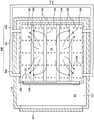
本发明的一个方式的水蒸气处理装置是一种利用水蒸气对用处理气体实施了处理后的基片进行处理的水蒸气处理装置,其具有:外侧腔室,其具有上下分隔开的第一处理室和第二处理室;第一内侧腔室,其被收纳于所述第一处理室中,以不与所述第一处理室的内壁面接触的方式载置在位于所述第一处理室的底面的固定部件上;第二内侧腔室,其被收纳于所述第二处理室中,以不与所述第二处理室的内壁面接触的方式载置在位于所述第二处理室的底面的固定部件上;对所述第一内侧腔室和所述第二内侧腔室分别供给水蒸气的水蒸气供给部;和从所述第一内侧腔室和所述第二内侧腔室分别进行排气的内侧排气部。A steam treatment apparatus according to one aspect of the present invention is a steam treatment apparatus for treating a substrate treated with a processing gas with steam, and includes an outer chamber having a first and second space separated up and down. a processing chamber and a second processing chamber; and a first inner chamber which is accommodated in the first processing chamber and is placed on the first inner wall so as not to come into contact with the inner wall surface of the first processing chamber on the fixing member on the bottom surface of the processing chamber; the second inner chamber, which is accommodated in the second processing chamber, is placed on the second inner wall so as not to come into contact with the inner wall surface of the second processing chamber on the fixing member on the bottom surface of the processing chamber; a water vapor supply part for supplying water vapor to the first inner chamber and the second inner chamber, respectively; and the first inner chamber and the second inner chamber The chambers are respectively exhausted inside the exhaust part.
发明效果Invention effect
根据本发明,提供一种能够以高生产性对用处理气体实施了处理后的基片进行水蒸气处理的水蒸气处理装置和水蒸气处理方法。According to the present invention, there are provided a steam treatment apparatus and a steam treatment method capable of performing steam treatment on a substrate treated with a treatment gas with high productivity.
附图说明Description of drawings
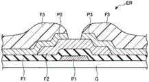
图1是表示实施方式的水蒸气处理装置所进行的后处理中应用的薄膜晶体管的一例的纵截面图。FIG. 1 is a longitudinal cross-sectional view showing an example of a thin film transistor used for post-processing performed by the water vapor treatment apparatus according to the embodiment.
图2A是表示蚀刻处理之后的电极附近的状态的示意图。FIG. 2A is a schematic view showing the state of the vicinity of the electrode after the etching process.
图2B是表示后处理之后的电极附近的状态的示意图。FIG. 2B is a schematic diagram showing the state of the vicinity of the electrodes after post-processing.
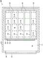
图3是表示包含实施方式的水蒸气处理装置的集结式机台的一例的平面图。FIG. 3 is a plan view showing an example of a cluster-type machine including the water vapor treatment apparatus according to the embodiment.
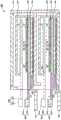
图4是实施方式的水蒸气处理装置的一例的纵截面图。FIG. 4 is a longitudinal cross-sectional view of an example of the steam treatment apparatus according to the embodiment.
图5是图4的V-V向视图,是与图4正交的方向的纵截面图。FIG. 5 is a view taken along the line V-V in FIG. 4 , and is a vertical cross-sectional view in a direction perpendicular to FIG. 4 .
图6是图4的VI-VI向视图,是实施方式的水蒸气处理装置的一例的横截面图。FIG. 6 is a view taken along arrow VI-VI of FIG. 4 , and is a cross-sectional view of an example of the water vapor treatment apparatus according to the embodiment.
图7是说明将搭载有基片的基片输送部件送入内侧腔室,将基片载置在载置台上的状况的纵截面图。7 is a longitudinal cross-sectional view illustrating a state in which the substrate conveying member on which the substrate is mounted is fed into the inner chamber, and the substrate is mounted on the mounting table.
图8是图7的VIII-VIII向视图。FIG. 8 is a view taken along line VIII-VIII of FIG. 7 .
图9是图7的IX-IX向视图。FIG. 9 is a view taken along line IX-IX of FIG. 7 .
图10是表示水蒸气供给部的供给管和内侧排气部的排气管的另一实施方式的横截面图。10 is a cross-sectional view showing another embodiment of the supply pipe of the water vapor supply portion and the exhaust pipe of the inner exhaust portion.
图11是图10的XI-XI向视图。FIG. 11 is a view taken along the line XI-XI of FIG. 10 .
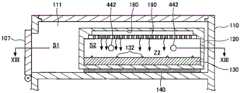
图12是表示水蒸气供给部的供给机构和内侧排气部的排气管的又一实施方式的纵截面图。12 is a longitudinal cross-sectional view showing still another embodiment of the supply mechanism of the water vapor supply portion and the exhaust pipe of the inner exhaust portion.
图13是图12的XIII-XIII向视图。FIG. 13 is a view taken along line XIII-XIII of FIG. 12 .
图14是表示实施方式的水蒸气处理装置的处理流程的一例的流程图。FIG. 14 is a flowchart showing an example of a processing flow of the water vapor processing apparatus according to the embodiment.
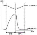
图15是表示气化器和内侧腔室的压力控制方法的一例的图。FIG. 15 is a diagram showing an example of a pressure control method of the vaporizer and the inner chamber.
附图标记说明Description of reference numerals
100 水蒸气处理装置100 Water vapor treatment device
110 外侧腔室110 Outer chamber
111 第一处理室111 First processing chamber
112 第二处理室112 Second processing chamber
120 第一内侧腔室120 first inner chamber
140 固定部件140 Fixed parts
150 第二内侧腔室150 Second medial chamber
170 固定部件170 Fixed parts
402、405 水蒸气供给部402, 405 Water vapor supply part
408、411 内侧排气部408, 411 Inner exhaust part
G 基片。G substrate.
具体实施方式Detailed ways
以下,参照附图,对本发明的实施方式的水蒸气处理装置进行说明。此外,在本说明书和附图中,对实质上相同的构成要素标注相同的附图标记,并省略重复的说明。Hereinafter, a steam treatment apparatus according to an embodiment of the present invention will be described with reference to the drawings. In addition, in this specification and drawings, the same code|symbol is attached|subjected to the substantially same component, and the overlapping description is abbreviate|omitted.
[实施方式][Embodiment]
<后处理中所应用的薄膜晶体管的一例><Example of Thin Film Transistor Applied in Post-processing>
首先,参照图1至图2B说明本发明的实施方式的水蒸气处理装置进行的后处理中所应用的薄膜晶体管的一例。在此,图1是表示实施方式的由水蒸气处理装置进行的后处理中所应用的薄膜晶体管的一例的纵截面图。另外,图2A是表示蚀刻处理之后的电极附近的状态的示意图,图2B是表示后处理之后的电极附近的状态的示意图。First, an example of a thin film transistor applied to the post-processing performed by the water vapor treatment apparatus according to the embodiment of the present invention will be described with reference to FIGS. 1 to 2B . Here, FIG. 1 is a longitudinal cross-sectional view showing an example of a thin film transistor applied to the post-processing by the water vapor processing apparatus according to the embodiment. In addition, FIG. 2A is a schematic diagram showing the state of the vicinity of the electrode after the etching treatment, and FIG. 2B is a schematic diagram showing the state of the vicinity of the electrode after the post-processing.
液晶显示装置(Liquid Crystal Display:LCD)等的平板显示器(Flat PanelDisplay:FPD)所使用的例如薄膜晶体管(Thin Film Transistor:TFT)形成在玻璃基片等的基片G上。具体而言,在基片G上,将栅极电极、栅极绝缘膜、半导体层等一边图案化一边依次层叠,由此形成TFT。此外,FPD用的基片G的平面尺寸随着世代的推移而大规模化,由实施方式的水蒸气处理装置所处理的基片G的平面尺寸至少包括例如从第6代的1500mm×1800mm程度的尺寸至第10代的2800mm×3000mm程度的尺寸。For example, a thin film transistor (Thin Film Transistor: TFT) used in a flat panel display (Flat Panel Display: FPD) such as a liquid crystal display device (Liquid Crystal Display: LCD) is formed on a substrate G such as a glass substrate. Specifically, on the substrate G, a gate electrode, a gate insulating film, a semiconductor layer, and the like are sequentially stacked while being patterned, thereby forming a TFT. In addition, the plane size of the substrate G for FPD increases with the passage of generations, and the plane size of the substrate G processed by the water vapor processing apparatus of the embodiment includes at least about 1500 mm×1800 mm, for example, in the sixth generation. The size of the 10th generation is about 2800mm×3000mm.
图1表示沟道蚀刻型的底部栅极型构造的TFT。图示的TFT在玻璃基片G(基片的一例)上形成栅极电极P1,在其上形成由SiN膜等构成的栅极绝缘膜F1,接着,在其上层层叠表面被n+掺杂的a-Si、氧化物半导体的半导体层F2。在半导体层F2的上层侧形成金属膜,通过蚀刻该金属膜,形成源电极P2(电极的一例)和漏电极P3(电极的一例)。FIG. 1 shows a channel-etched bottom gate type TFT. In the TFT shown in the figure, a gate electrode P1 is formed on a glass substrate G (an example of the substrate), a gate insulating film F1 made of a SiN film or the like is formed thereon, and an n+-doped film is laminated on the upper layer. a-Si, the semiconductor layer F2 of an oxide semiconductor. A metal film is formed on the upper layer side of the semiconductor layer F2, and the metal film is etched to form a source electrode P2 (an example of an electrode) and a drain electrode P3 (an example of an electrode).
在形成源电极P2和漏电极P3之后,蚀刻n+掺杂的半导体层F2的表面,由此形成TFT的沟道部。接着,为了保护表面,例如形成由SiN膜构成的钝化膜(未图示)。接着,使源电极P2、漏电极P3经由形成在钝化膜的表面的接触孔与ITO(Indium Tin Oxide)等的未图示的透明电极连接,从而使该透明电极与驱动电路、驱动电极连接,由此形成FPD。此外,除了图示例的底部栅极型构造的TFT以外,还具有顶部栅极型构造的TFT等。After the source electrode P2 and the drain electrode P3 are formed, the surface of the n+-doped semiconductor layer F2 is etched, thereby forming a channel portion of the TFT. Next, in order to protect the surface, a passivation film (not shown) made of, for example, a SiN film is formed. Next, the source electrode P2 and the drain electrode P3 are connected to a transparent electrode (not shown) such as ITO (Indium Tin Oxide) through contact holes formed on the surface of the passivation film, and the transparent electrode is connected to the driving circuit and the driving electrode. , thereby forming an FPD. In addition to the bottom gate type structure TFT shown in the figure, there is also a top gate type structure TFT and the like.
在图示的TFT中,作为用于形成源电极P2和漏电极P3的金属膜,例如能够使用从下层侧依次层叠钛膜、铝膜、钛膜的Ti/Al/Ti构造的金属膜。如图1所示,例如在Ti/Al/Ti构造的金属膜的表面图案化抗蚀剂膜F3。对该金属膜,使用氯气(Cl2)、硼酰氯(BCl3)、四氯化碳(CCl4)等的氯系的蚀刻气体(卤素系的蚀刻气体)进行干蚀刻处理,由此形成源电极P2和漏电极P3。In the illustrated TFT, as the metal film for forming the source electrode P2 and the drain electrode P3, for example, a metal film of a Ti/Al/Ti structure in which a titanium film, an aluminum film, and a titanium film are stacked in this order from the lower layer side can be used. As shown in FIG. 1 , for example, a resist film F3 is patterned on the surface of a metal film having a Ti/Al/Ti structure. This metal film is dry-etched using a chlorine-based etching gas (halogen-based etching gas) such as chlorine gas (Cl2 ), boronyl chloride (BCl3 ), carbon tetrachloride (CCl4 ), etc., thereby forming a source electrode P2 and drain electrode P3.
如上所述,当使用氯系的蚀刻气体对源电极P2、漏电极P3进行图案化时,如图2A所示,氯(Cl)能够附着在抗蚀剂膜F3上。并且,作为蚀刻后的金属膜的电极P2(P3)也能够附着氯或作为氯和铝的化合物的氯化铝(氯系化合物)。如上所述,为了之后的抗蚀剂膜F3的剥离而将附着有氯的状态的TFT在大气中输送时,附着在抗蚀剂膜F3、电极P2(P3)的氯会与大气中的水分的氢发生反应而生成氯酸,并且,残留的羟基(OH)会与铝发生反应而生成氢氧化铝(Al(OH)3),成为引起电极P2(P3)的腐蚀的主要原因。As described above, when the source electrode P2 and the drain electrode P3 are patterned using a chlorine-based etching gas, as shown in FIG. 2A , chlorine (Cl) can adhere to the resist film F3 . In addition, chlorine or aluminum chloride (a chlorine-based compound), which is a compound of chlorine and aluminum, can also be attached to the electrode P2 (P3), which is a metal film after etching. As described above, when the chlorine-adhered TFT is transported in the atmosphere for the subsequent peeling of the resist film F3, the chlorine adhering to the resist film F3 and the electrode P2 (P3) will interact with moisture in the atmosphere. The remaining hydrogen reacts to generate chloric acid, and the remaining hydroxyl group (OH) reacts with aluminum to generate aluminum hydroxide (Al(OH)3 ), which is the main cause of corrosion of the electrode P2 (P3).
所以,在本实施方式中,对使用氯系的蚀刻气体进行蚀刻处理而形成电极P2(P3)后的基片G,进行提供水蒸气(H2O水蒸气、非等离子体水蒸气)的水蒸气处理(以下称为“后处理”)。通过该水蒸气处理,能够除去附着在电极P2(P3)上的氯。即,如图2B所示,H2O水蒸气与附着在电极P2(P3)上的氯或氯系化合物反应而生成氯化氢(HCl),氯化氢从电极P2(P3)脱离,从而除去氯和氯系化合物,抑制成为腐蚀原因的氢氧化铝的产生。Therefore, in the present embodiment, the substrate G on which the electrodes P2 (P3) are formed by etching with a chlorine-based etching gas is subjected to water supplying water vapor (H2 O water vapor, non-plasma water vapor) Steam treatment (hereinafter referred to as "post-treatment"). Chlorine adhering to the electrode P2 (P3) can be removed by this steam treatment. That is, as shown in FIG. 2B , H2 O water vapor reacts with chlorine or a chlorine-based compound adhering to the electrode P2 (P3) to generate hydrogen chloride (HCl), and the hydrogen chloride is desorbed from the electrode P2 (P3), thereby removing chlorine and chlorine It is a compound that suppresses the generation of aluminum hydroxide which is a cause of corrosion.
<包含实施方式的水蒸气处理装置的集结式机台的一例><An example of an integrated machine including the water vapor treatment device of the embodiment>
接着,参照图3说明包含实施方式的水蒸气处理装置的集结式机台的一例。在此,图3是表示包含实施方式的水蒸气处理装置的集结式机台的一例的平面图。Next, with reference to FIG. 3, an example of the assembly-type machine which contains the water vapor|steam processing apparatus of embodiment is demonstrated. Here, FIG. 3 is a plan view showing an example of a cluster-type machine including the water vapor treatment apparatus according to the embodiment.
集结式机台200是多腔室型,作为在真空气氛下能够实施串行处理的系统而构成。在集结式机台200中,在配置于中央的俯视呈六边形的输送腔室20(称为传输模块)的一边,隔着门阀12安装有装载互锁腔室10。另外,在输送腔室20的其他的四个边,分别隔着门阀31安装有四个处理腔室30A、30B、30C、30D(也称为处理模块)。并且,在输送腔室20的剩余的一个边,隔着门阀32安装有本实施方式的水蒸气处理装置100(后处理腔室)。The
各腔室均被控制为相同程度的真空气氛,在打开门阀31、32来进行输送腔室20与各腔室之间的基片G的交接时,被调整为使得不产生腔室间的压力变动。The chambers are controlled to have the same degree of vacuum atmosphere, and when the
装载互锁腔室10隔着门阀11与载体(未图示)连接,在载体收纳有载置在载体载置部(未图示)上的多个基片G。装载互锁腔室10能够在常压气氛与真空气氛之间切换内部的压力气氛,在与载体之间进行基片G的交接。The
装载互锁腔室10例如呈两层地层叠,在各自的装载互锁腔室10内设置有用于保持基片G的保持架14、用于进行基片G的位置调节的定位器13。在装载互锁腔室10被控制为真空气氛之后,门阀12打开而与同样被控制为真空气氛的输送腔室20连通,从装载互锁腔室10对输送腔室20在X2方向进行基片G的交接。The
在输送腔室20内搭载有在作为周向的X1方向上自由旋转且向各腔室侧自由滑动的输送机构21。输送机构21将从装载互锁腔室10接收的基片G输送至所期望的腔室,门阀31、32打开,从而向被调整为与装载互锁腔室10相同程度的真空气氛的各腔室进行基片G的交接。Inside the
图示例中处理腔室30A、30B、30C、30D都是等离子体处理装置,在各腔室中,都进行使用卤素系的蚀刻气体(氯系的蚀刻气体)的干蚀刻处理。作为集结式机台200中的基片G的处理的一系列的流程,首先,从输送腔室20向处理腔室30A交接基片G,在处理腔室30A中实施干蚀刻处理。被实施干蚀刻处理的基片G被交接到输送腔室20(以上,基片G在X3方向上动)。In the illustrated example, the
被交接到输送腔室20的基片G,参照图2A如已经说明的方式,在形成在基盘G的表面的源电极P2和漏电极P3附着有氯或氯系化合物。因此,从输送腔室20对水蒸气处理装置100交接基片G,在水蒸气处理装置100中进行利用水蒸气处理的后处理。通过后处理,从电极P2(P3)除去氯或氯系化合物,将除去了氯等的基片G交接到输送腔室20(以上,基片G在X7方向上动)。The substrate G transferred to the
以下,同样地进行输送腔室20与处理腔室30B之间的X4方向的基片G的交接,进行输送腔室20与水蒸气处理装置100之间的X7方向的基片G的交接。另外,进行输送腔室20与处理腔室30C之间的X5方向的基片G的交接,进行输送腔室20与水蒸气处理装置100之间的X7方向的基片G的交接。此外,进行输送腔室20与处理腔室30D之间的X6方向的基片G的交接,进行输送腔室20和水蒸气处理装置100之间的X7方向的基片G的交接。Hereinafter, the transfer of the substrate G in the X4 direction between the
如上所述,集结式机台200包括:使用氯系的蚀刻气体进行干蚀刻处理(等离子体蚀刻处理)的多个蚀刻腔室;和利用水蒸气处理进行后处理的水蒸气处理装置100。而且,其是按照以基于各蚀刻腔室中的基片G的蚀刻处理和水蒸气处理装置100中的水蒸气处理的后处理为一系列流程的处理方案,在每个蚀刻腔室进行该流程的集结式机台。在集结式机台200中,使以下详细说明的水蒸气处理装置100为上下二级配置,能够形成生产性更高的集结式机台。As described above, the cluster-
此外,各处理腔室都可以为进行干蚀刻处理的方式以外的方式。例如各处理腔室可以为按顺序地进行CVD(Chemical Vaper Deposition)处理、PVD(Physical VaperDeposition)处理等的成膜处理和蚀刻处理的方式的集结式机台。另外,构成集结式机台的输送腔室的平面形状不限于图示例的六边形形状,可以使用与连接的处理腔室的个数相应的多边形状的输送腔室。In addition, each processing chamber may be of a method other than the method of performing the dry etching process. For example, each processing chamber may be an integrated machine in which a film formation process such as a CVD (Chemical Vaper Deposition) process and a PVD (Physical Vaper Deposition) process and an etching process are sequentially performed. In addition, the planar shape of the transport chambers constituting the cluster-type table is not limited to the hexagonal shape shown in the illustration, and polygonal transport chambers can be used according to the number of processing chambers to be connected.
<实施方式的水蒸气处理装置><The steam treatment device of the embodiment>
接着,参照图4至图9说明包含实施方式的水蒸气处理装置的集结式机台的一例。在此,图4是实施方式的水蒸气处理装置的一例的纵截面图。另外,图5是图4的V-V向视图,是与图4正交的方向的纵截面图,图6是图4的VI-VI向视图,是实施方式的水蒸气处理装置的一例的横截面图。另外,图7是说明将搭载有基片的基片输送部件送入内侧腔室,将基片载置在载置台的状况的纵截面图。并且,图8是图7的VIII-VIII向视图,图9是图7的IX-IX向视图。Next, an example of a cluster-type machine including the water vapor treatment apparatus according to the embodiment will be described with reference to FIGS. 4 to 9 . Here, FIG. 4 is a longitudinal cross-sectional view of an example of the steam treatment apparatus according to the embodiment. 5 is a view taken along the line V-V in FIG. 4, which is a vertical cross-sectional view in a direction perpendicular to FIG. 4, and FIG. 6 is a view taken along the line VI-VI of FIG. picture. In addition, FIG. 7 is a longitudinal cross-sectional view illustrating a state in which the substrate conveying member on which the substrate is mounted is fed into the inner chamber, and the substrate is mounted on the mounting table. 8 is a view taken along the line VIII-VIII of FIG. 7 , and FIG. 9 is a view taken along the line IX-IX of FIG. 7 .
水蒸气处理装置100是利用水蒸气对用氯系的蚀刻气体(处理气体的一例)实施了处理的基片G进行处理的装置。水蒸气处理装置100包括:具有上下分隔开的第一处理室111和第二处理室112的外侧腔室110;载置在第一处理室111内的第一内侧腔室120;和载置在第二处理室112内的第二内侧腔室150。The water
外侧腔室110包括主体103、上盖104和下盖106,主体103、上盖104和下盖106都由铝或者铝合金形成。The
主体103包括:在水平方向延伸的将第一处理室111与第二处理室112上下分隔的分隔板102;与分隔板102相连续地在铅垂方向延伸的侧壁101。侧壁101的平面形状为矩形,在侧壁101的上端,以向内侧突出设置的方式设置有平面形状为矩形的卡合台阶部103a,在侧壁101的下端,以向内侧突出设置的方式设置有平面形状为矩形的卡合台阶部103b。The
矩形的卡合台阶部103a与同样平面形状为矩形的上盖104所具有的卡合突起104a卡合,两者通过固定机构(未图示)固定在一起。此外,上盖104的一边经转动部(未图示)可转动地安装在主体103的一边。例如在对第一内侧腔室120等进行维护时,从主体103取下上盖104,能够从第一处理室111搬出第一内侧腔室120。然后,将进行了维护的第一内侧腔室120搬入第一处理室111后,在主体103安装上盖104,由此能够在第一处理室111设置第一内侧腔室120。The rectangular
另外,矩形的卡合台阶部103b与同样平面形状为矩形的下盖106所具有的卡合突起106a卡合,两者通过固定机构(未图示)固定在一起。然后,在对第二内侧腔室150等进行维护时,从主体103取下下盖106,能够从第二处理室112搬出第二内侧腔室150。然后,将进行了维护的第二内侧腔室150搬入第二处理室112后,在主体103安装下盖106,由此能够在第二处理室112设置第二内侧腔室150。In addition, the rectangular engaging
铝或者铝合金制的外侧腔室110有充足的热容量。因此,在收纳集结式机台200的洁净室等的环境中,即使不对在进行水蒸气处理时成为高温的第1内侧腔室120或者第2内侧腔室150设置特别的隔热措置,例如也能够一直保持60℃程度的温度。因此,在对水蒸气处理装置100等进行维护时,操作员能够触碰到外侧腔室110地进行维护等的作业。The
第一内侧腔室120是由铝或者铝合金形成的壳体。如图5所示,在第一内侧腔室120所具有的一个侧面形成有第一内侧开口123,并经由转动部125安装有能够以打开和关闭第一内侧开口123的方式在Y1方向转动的开闭盖124。The first
另外,在外侧腔室110之中的与第一内侧开口123对应的位置形成有第一外侧开口105,滨经由转动部115安装有能够以打开和关闭第一外侧开口105的方式在Y2方向转动的开闭盖107。In addition, a first
第二内侧腔室150也同样是由铝或者铝合金形成的壳体。如图5所示,在第二内侧腔室150所具有的一个侧面形成有第二内侧开口153,且经由转动部155安装有能够以打开和关闭第二内侧开口153的方式在Y1方向转动的开闭盖154。The second
另外,在外侧腔室110之中、与第二内侧开口153对应的位置形成有第二外侧开口108,且经由转动部116安装有能够以打开和关闭第二内侧开口108的方式在Y2方向转动的开闭盖109。In addition, a second
通过使开闭盖124、107打开,能够从输送腔室20将基片G交接到第一内侧腔室120,同样地,能够将水蒸气处理后的基片G从第一内侧腔室120交接到输送腔室20。另外,通过使开闭盖154、109打开,能够从输送腔室20将基片G交接到第二内侧腔室150,同样地,能够将水蒸气处理后的基片G从第二内侧腔室150交接到输送腔室20。By opening the opening and closing covers 124 and 107 , the substrate G can be transferred from the
在第一处理室111中,第一内侧腔室120不与第一处理室111的内壁面接触,载置在位于第一处理室111的底面的多个固定部件140上。同样地,第二内侧腔室150不与第二处理室112的内壁面接触,载置在位于第二处理室112的底面的多个固定部件170。通过该结构,在第一处理室111与第一内侧腔室120之间形成空间S1,在第二处理室112与第二内侧腔室150之间形成空间S3。另外,在对基片G进行水蒸气处理的第一内侧腔室120的内部形成处理空间S2,同样,在对基片G进行水蒸气处理的第二内侧腔室150的内部形成处理空间S4。In the
固定部件140、170具有隔热性,由特氟龙(注册商标)、氧化铝(Al2O3)等的陶瓷、热传导率低的不锈钢等形成。第一内侧腔室120不与第一处理室111的内壁面接触,隔着具有隔热性的固定部件140被固定在第一处理室111的底面。通过该结构,如以下说明的那样,能够抑制进行了温度调节控制的第一内侧腔室120的热传递到外侧腔室110。同样地,第二内侧腔室150不与第二处理室112的内壁面接触,隔着具有隔热性的固定部件170被固定在第二处理室112的底面。通过该结构,能够抑制进行了温度调节控制的第二内侧腔室150的热传递到外侧腔室110。The fixing
在第一内侧腔室120的底面配置有用于载置基片G的第一支承部件130(第一载置台)。第一支承部件130是由铝或者铝合金形成的、长条形的块状部件,如图4和图6所示,多个第一支承部件130隔开间隙地配置。在该间隙形成有用于收纳构成图7至图9所示的基片输送部件500的轴部件510的收纳槽134。On the bottom surface of the first
同样地,在第二内侧腔室150的底面配置有用于载置基片G的第二支承部件160(第二载置台)。第二支承部件160是由铝或者铝合金形成的、长条形的块状部件,多个第二支承部件160隔开间隙地配置。在该间隙形成有收纳槽164。Similarly, on the bottom surface of the second
在第一支承部件130的上表面隔开间隔地设置有多个突起132,在突起132之上载置基片G。同样地,在第二支承部件160上表面隔开间隔地设置有多个突起162,在突起162上载置基片G。A plurality of
在外侧腔室110中,安装有用于计测空间S1内的压力的压力计302,并安装有用于计测空间S3内的压力的压力计306。另外,在第一内侧腔室120中安装有用于计测处理空间S2内的压力的压力计304,在第二内侧腔室150中安装有用于计测处理空间S4内的压力的压力计308。上述的压力计302、304、306、308的监视信息被发送到控制部600。In the
第一内侧腔室120连接有与构成水蒸气供给部402的气化器400相通的供给配管,在供给配管设置有供给阀401。另外,第一内侧腔室120连接有与构成内侧排气部408的涡轮分子泵等的真空泵406(内侧排气部的一例)相通的排气配管,在排气配管设置有排气阀407。另外,外侧腔室110和第一内侧腔室120连接有来自供给氮气气体(N2)等惰性气体的惰性气体供给部415的二个系统的供给配管。在各供给配管设置有供给阀416。A supply pipe communicating with the
在第二内侧腔室150连接有与构成水蒸气供给部405的气化器403相通的供给配管,在供给配管设置有供给阀404。另外,在第二内侧腔室150连接有与构成内侧排气部411的涡轮分子泵等的真空泵409(内侧排气部的一例)相通的排气配管,在排气配管设置有排气阀410。另外,外侧腔室110和第二内侧腔室150连接有来自供给氮气气体(N2)等惰性气体的惰性气体供给部417的二个系统的供给配管。在各供给配管设置有供给阀418。A supply pipe communicating with the
在外侧腔室110中,来自真空泵412(外侧排气部的一例)的二个系统的排气配管以与空间S1、S3相通的方式连接,在各排气配管设置有排气阀413、414。In the
使真空泵412动作,将空间S1、S3调整为真空气氛,进行差压控制使得同样被调整为真空气氛的输送腔室20之间的压力差尽可能小。The
另外,一边对空间S1内进行抽真空一边从惰性气体供给部415供给惰性气体,能够对残留在空间S1内的水蒸气、氯化氢等进行吹扫。同样地,一边对空间S3内进行抽真空一边从惰性气体供给部417供给惰性气体,能够对残留在空间S3内的水蒸气、氯化氢等进行吹扫。此外,通过对空间S1和空间S3进行抽真空,可获得能够抑制第一内侧腔室120及第二内侧腔室150与外侧腔室110之间的传热的效果。Moreover, the inert gas is supplied from the inert
另外,在第一内侧腔室120中,通过使内侧排气部408工作,将处理空间S2调整为真空气氛,并通过使水蒸气供给部402工作,对处理空间S2内供给水蒸气,能够进行载置在处理空间S2内的基片G的水蒸气处理。另外,与空间S1同样地一边对处理空间S2内进行抽真空,一边从惰性气体供给部415供给惰性气,由此能够对残留在处理空间S2内的水蒸气、氯化氢等进行吹扫。In addition, in the first
另外,在第二内侧腔室150中,通过使内侧排气部411工作,将处理空间S4调整为真空气氛,并通过使水蒸气供给部405工作,对处理空间S4内供给水蒸气,能够进行载置在处理空间S4内的基片G的水蒸气处理。另外,与空间S3同样地一边对处理空间S4内进行抽真空,一边从惰性气体供给部417供给惰性气,能够对残留在处理空间S4内的水蒸气、氯化氢等进行吹扫。In the second
在第一载置台130设置有供温度调节介质流通的温度调节介质流路136(第一温度调节部的一例)。在图示例的温度调节介质流路136中,例如温度调节介质流路136的一端为温度调节介质的流入部,另一端为温度调节介质的流出部。作为温度调节介质能够使用Galden(注册商标)和Florinert(注册商标)。The
第一温度调节部136不包含由制冷机(未图示)形成的温度调节源200,仅指内置在第一载置台130中的温度调节介质流路。此外,第一温度调节部可以为加热器等,在该情况下,作为电阻体的加热器能够由钨、钼或者这些金属中的任一者与氧化铝、钛等的化合物形成。The first
另一方面,在第二载置台160设置有供温度调节介质流通的温度调节介质流路166(第二温度调节部的一例)。在图示例的温度调节介质流路166中,例如温度调节介质流路166的一端为温度调节介质的流入部,另一端为温度调节介质的流出部。On the other hand, the
与第一温度调节部136相同,第二温度调节部166也不包含由制冷机(未图示)形成的温度调节源200,仅指内置在第二载置台160中的温度调节介质流路。Like the first
由制冷机形成的温度调节源200包括用于控制温度调节介质的温度、排出流量的主体部和压送温度调节介质的泵(均未图示)。The
温度调节源200与温度调节介质流路136,经由从温度调节源200供给温度调节介质的送出流路202和使流过温度调节介质流路136的温度调节介质返回温度调节源200的返回流路204连接在一起。另外,温度调节源200与温度调节介质流路166,经由从温度调节源200供给温度调节介质的送出流路206和使流过温度调节介质流路166的温度调节介质返回温度调节源200的返回流路208连接在一起。此外,如图示例子所示,第一温度调节部136和第二温度调节部166与共用的温度调节源200连接的方式之外,还可以为第一温度调节部136和第二温度调节部166各自具有专用的温度调节源的方式。在任一方式中,第一温度调节部136和第二温度调节部166都能够分别单独地控制。The
如上所述,单独控制第一温度调节部136和第二温度调节部166,例如在对第二内侧腔室150进行维护时,能够仅使第一内侧腔室120运行来进行基片G的水蒸气处理。在此,第一内侧腔室120和第二内侧腔室150如上所述分别具有专用的水蒸气供给部402、405、内侧排气部408、411等,上述的各构成部也同样能够单独控制。As described above, by independently controlling the first
如上所述,构成第一内侧腔室120和第二内侧腔室150的各构成部分别能够单独地控制,在一个腔室因维护等而停止运行的情况下,能够继续另一个腔室的运行。因此,能够消除水蒸气处理装置100的运行完全停止的情况,能够以高生产性地进行水蒸气处理。As described above, each of the components constituting the first
另外,在水蒸气处理装置100中,将外侧腔室110上下分隔开,形成第一处理室111和第二处理室112,在各处理室收纳第一内侧腔室120和第二内侧腔室150,在各腔室内实施水蒸气处理。因此,能够使实际上执行水蒸气处理的腔室的容量尽可能低容量化。所以,能够将尽可能低容量的第一内侧腔室120和第二内侧腔室150从第一处理室111和第二处理室112取下,通过进行它们的内部的表面补修处理(耐腐蚀涂层处理等)来进行补修,所以也能够容易进行维护。In addition, in the water
此外,图示例的第一支承部件130和第二支承部件160是由隔着多个收纳槽134配置的多个长条形的块状部件形成的载置台,但是也可以为其以外的方式。例如,由从第一内侧腔室120和第二内侧腔室150的各底面向上方突出设置的多个销状的轴部件形成,在各轴部件的前端设置有用于直接载置基片G的突起的方式等。In addition, although the
另外,图示例的气化器400、403、真空泵406、409各自使用单独的气化器、真空泵,但是也可以为使用共用的气化器和共用的真空泵的方式。在该方式中,从一个气化器起的二个系统的供给管与第一内侧腔室120和第二内侧腔室150连接,在各供给管设置有专用的供给阀,单独执行各供给阀的开闭控制。同样地,从一个气化器起的二个系统的排气管与第一内侧腔室120和第二内侧腔室150连接,在各排气管设置有专用的排气阀,单独执行各排气阀的开闭控制。在该方式中,能够降低气化器和真空泵的个数,能够削减装置的制造成本。In addition, although the
控制部600控制水蒸气处理装置100的各构成部,例如、水蒸气供给部402、405、内侧排气部408、411、惰性气体供给部415、417、温度调节源200等的工作。控制部600具有CPU(Central Processing Unit)、ROM(Read Only Memory)和RAM(Random Access Memory)。CPU按照收纳在RAM等的存储区域中的方案(处理方案),执行规定的处理。方案中设定有对处理条件的水蒸气处理装置100的控制信息。The
控制信息例如包括气化器400、403的压力、第一内侧腔室120和第二内侧腔室150的压力、从气化器400、403供给的水蒸气的温度、流量、水蒸气供给处理和来自各腔室的排气处理的处理时间和时刻。The control information includes, for example, the pressures of the
方案和控制部600所使用的程序例如可以存储在硬盘或光盘、光磁盘等中。另外,方案等可以为以保存于CD-ROM、DVD、存储卡等的可移动的计算机可读取的存储介质的状态设置于控制部600,且能够读取的方式。控制部600还可以包括进行指令的输入操作等的键盘、鼠标等的输入装置、将水蒸气处理装置100的运行状況可视化显示的显示器等的显示装置、以及打印机等的输出装置等的用户接口。The program used by the scheme and
如图7至图9所示,向第一内侧腔室120和第二内侧腔室150去的基片G的交接,通过在将基片G载置于基片输送部件500上的状态下将基片G收纳于第一内侧腔室120等来进行。基片输送部件500具有多个(图示例中为四个)的轴部件510和将多个轴部件510彼此连结的连结部件520。在此,相对于连结部件520,多个轴部件510安装到与处于第一内侧腔室120内的各自的收纳槽134、处于第二内侧腔室150内的收纳槽154相对应的位置。另外,连结部件520与机械臂(未图示)等连接。As shown in FIGS. 7 to 9 , the transfer of the substrates G to the first
当列举第一内侧腔室120进行说明时,将开闭盖124、107同时或按顺序地打开,由此,将输送腔室20和第一内侧腔室120开放。接着,将载置有基片G的基片输送部件500通过机械臂(未图示)等插入第一内侧腔室120内(图7和图8的点划线的状态)。接着,使机械臂在Y3方向下降,多个轴部件510收纳在对应的收纳槽134中,从而搭载在轴部件510上的基片G被载置在第一支承部件130上(图7和图8的实线的状态)。When the first
在第一内侧腔室120等中基片G的水蒸气处理结束后,通过机械臂等抬起多个轴部件510,轴部件510从收纳槽134向上方突出地支承基片G。将支承基片G的基片输送部件500从第一内侧腔室120等抽出,进行基片G的送出。After the water vapor treatment of the substrate G in the first
接着,参照图10至图13说明水蒸气供给部的供给管和内侧排气部的排气管的另一实施方式。在此,图10是表示水蒸气供给部的供给管和内侧排气部的排气管的另一实施方式的横截面图,图11是图10的XI-XI向视图。另外,图12是表示水蒸气供给部的供给机构和内侧排气部的排气管的又一实施方式的纵截面图,图13是图12的XIII-XIII向视图。此外,在任一方式中,虽然都说明了第一内侧腔室120中的供给管(供给机构)、排气管,但是在第二内侧腔室150中也能够使用相同的结构。Next, another embodiment of the supply pipe of the water vapor supply portion and the exhaust pipe of the inner exhaust portion will be described with reference to FIGS. 10 to 13 . Here, FIG. 10 is a cross-sectional view showing another embodiment of the supply pipe of the water vapor supply part and the exhaust pipe of the inner exhaust part, and FIG. 11 is a view taken along the line XI-XI of FIG. 10 . In addition, FIG. 12 is a longitudinal cross-sectional view showing still another embodiment of the supply mechanism of the water vapor supply part and the exhaust pipe of the inner exhaust part, and FIG. 13 is a view taken along arrow XIII-XIII of FIG. 12 . In addition, although the supply pipe (supply means) and the exhaust pipe in the first
图10和图11所示的实施方式中,由主管421和从主管421分支的多个(图示例为三个)支管422形成供给管420,各支管422贯通外侧腔室110的侧壁,与第一内侧腔室120的侧壁连接。供给管420与图4等所示的气化器400相连通。另外,由主管431和从主管431分支的多个(图示例为三个)支管432形成排气管430。各支管432贯通外侧腔室110的侧壁(与支管422所贯通的侧壁相对的相反侧的侧壁),与第一内侧腔室120的侧壁(与支管422所贯通的侧壁相对的相反侧的侧壁)连接。排气管430与图4等所示的真空泵409相通。In the embodiment shown in FIGS. 10 and 11 , the
如图10所示,在第一内侧腔室120内,供给管420的多个支管422以层状在Z1方向供给水蒸气。通过该供给方式,能够对载置于第一内侧腔室120内的基片G的整个区域有效地供给水蒸气。另外,能够通过排气管430的多个支管432,将第一内侧腔室120内的水蒸气和后处理所生成的氯化氢(HCl)等有效地排气。此外,支管422、432可以为图示例的三个以外的数量(一个、五个等)。As shown in FIG. 10 , in the first
另一方面,在图12和图13所示的实施方式中,在第一内侧腔室120的上方设置有用于供给水蒸气的流入空间180,在流入空间180的下方设置喷淋头供给部190,经由喷淋头供给部190向下方的基片G在Z2方向上呈喷淋状供给水蒸气。在铅垂方向上呈喷淋状地被供给的水蒸气一边在Z3方向上扩散,一边被供给到基片G的整个区域。On the other hand, in the embodiment shown in FIGS. 12 and 13 , an
另外,在第一内侧腔室120的侧壁,通过连接有四个支管442且贯通外侧腔室110,使各支管442与主管441连接,从而形成排气管440。In addition, four
如图12和图13所示,在第一内侧腔室120内,从顶部呈喷淋状供给水蒸气,能够对载置在第一内侧腔室120内的基片G的整个区域有效地供给水蒸气。此外,替代图示例的喷淋头供给部190,可以为将一个或多个供给配管连接到第一内侧腔室120的顶部,经供给配管将水蒸气从顶部供给的方式。As shown in FIGS. 12 and 13 , in the first
<实施方式的水蒸气处理方法><The steam treatment method of the embodiment>
接着,参照图14和图15说明实施方式的水蒸气处理方法的一例。在此,图14是表示实施方式的水蒸气处理装置的处理流程的一例的流程图,图15是表示气化器和内侧腔室的压力控制方法的一例的图。Next, an example of the steam treatment method of the embodiment will be described with reference to FIGS. 14 and 15 . Here, FIG. 14 is a flowchart showing an example of a processing flow of the steam treatment apparatus according to the embodiment, and FIG. 15 is a diagram showing an example of a pressure control method of the vaporizer and the inner chamber.
如图14所示,实施方式的水蒸气处理方法,首先,对气化器的供给阀进行开控制(步骤S10),接着,从气化器对内侧腔室供给水蒸气,保持规定时间,执行规定时间的后处理(步骤S12)。As shown in FIG. 14 , in the water vapor treatment method of the embodiment, first, the supply valve of the vaporizer is controlled to open (step S10 ), and then water vapor is supplied from the vaporizer to the inner chamber, maintained for a predetermined time, and executed. Post-processing for a predetermined time (step S12).
在该后处理时进行调整,使得通过第一温度调节部等对第一支承部件等进行温度调节控制,使内侧腔室内的温度总是低于气化器的温度。通过该调整,能够抑制供给的水蒸气的液化。提供的水蒸气的温度例如在20℃至50℃程度的情况下,将内侧腔室的温度调整为40℃至120℃。During this post-processing, it is adjusted so that the temperature in the inner chamber is always lower than the temperature of the vaporizer by performing the temperature adjustment control of the first support member or the like by the first temperature adjustment unit or the like. By this adjustment, the liquefaction of the supplied water vapor can be suppressed. When the temperature of the supplied water vapor is, for example, about 20°C to 50°C, the temperature of the inner chamber is adjusted to 40°C to 120°C.
在对内侧腔室供给水蒸气时,将充填到气化器的罐的水控制到规定的温度,成为由蒸气压加压的状态。另一方面,内侧腔室成为由排气管430、440排气至0.1Torr(13.33Pa)以下的状态。如上所述,通过气化器的罐内的压力与内侧腔室的压力的压力差(差压),向内侧腔室供给水蒸气。此时,使差压尽可能大,能够对内侧腔室有效地供给水蒸气。并且,使内侧腔室的容积尽可能小,能够在更短时间升压至规定的压力,因此生产性提高。所以,优选气化器的压力尽可能高,内侧腔室的压力尽可能低。但是,从气化器的控制容易性的观点出发,优选气化器以尽可能低温度进行运转控制。所以,例如如上所述,将20℃至50℃程度的温度的水蒸气供给到内侧腔室。此外,20℃的水蒸气的平衡蒸气压为20Torr(2666Pa)程度,50℃的水蒸气的平衡蒸气压为90Torr(11997Pa)程度。When water vapor is supplied to the inner chamber, the water to be filled in the tank of the vaporizer is controlled to a predetermined temperature to be pressurized by the vapor pressure. On the other hand, the inner chamber is in a state of being exhausted to 0.1 Torr (13.33 Pa) or less by the
如上所述,从气化器的运转控制的观点出发,优选尽可能供给低温的水蒸气,另一方面,当水蒸气的温度低时,气化器的压力变低,难以使气化器与内侧腔室的差压变大。因此,难以对内侧腔室有效地供给水蒸气,水蒸气处理时间有可能变长。As described above, from the viewpoint of the operation control of the vaporizer, it is preferable to supply the water vapor as low as possible. On the other hand, when the temperature of the vapor is low, the pressure of the vaporizer becomes low, and it becomes difficult to make the vaporizer and the vaporizer difficult. The differential pressure in the inner chamber becomes larger. Therefore, it is difficult to efficiently supply water vapor to the inner chamber, and the water vapor treatment time may be prolonged.
然而,在图4等所示的水蒸气处理装置100中,第一内侧腔室120、第二内侧腔室150的容量尽可能为低容量,在提供的水蒸气的温度低的情况下,能够尽可能在短时间增大气化器与内侧腔室的差压。如图15所示,因水蒸气的供给,气化器的压力逐渐减小,内侧腔室的压力急剧增大。However, in the water
此外,对气化器的供给阀进行开控制(步骤S10)时,内侧腔室的排气阀可以进行闭控制,也可以进行开控制。In addition, when the supply valve of the vaporizer is controlled to open (step S10 ), the exhaust valve of the inner chamber may be controlled to be closed or controlled to be open.
返回图14,在后处理结束之后,对气化器的供给阀进行闭控制(步骤S14),接着,对内侧腔室的排气阀进行开控制(步骤S16),从而对内侧腔室内的水蒸气和后处理所生成的氯化氢(HCl)等进行排气。如图15所示,因气化器的供给阀的闭控制和水蒸气、氯化氢(HCl)等的排气,气化器的压力逐渐增大,内侧腔室的压力急剧减小,形成能够对新的基片进行水蒸气处理的状态。此外,除了来自内侧腔室的排气之外,可以适当进行利用惰性气体的吹扫。Returning to FIG. 14 , after the post-processing is completed, the supply valve of the vaporizer is controlled to be closed (step S14 ), and then the exhaust valve of the inner chamber is controlled to be opened (step S16 ), so that the water in the inner chamber is controlled to be closed (step S16 ). The steam and hydrogen chloride (HCl) generated in the post-processing are exhausted. As shown in FIG. 15 , due to the closing control of the supply valve of the vaporizer and the exhaust of water vapor, hydrogen chloride (HCl), etc., the pressure of the vaporizer gradually increases, and the pressure of the inner chamber decreases sharply, forming a The state of the new substrate undergoing water vapor treatment. Further, in addition to the exhaust gas from the inner chamber, purging with an inert gas may be appropriately performed.
根据图示的水蒸气处理方法,使用水蒸气处理装置100,能够以高生产性进行水蒸气处理。According to the steam treatment method shown in the figure, the steam treatment can be performed with high productivity using the
另外,在对第一内侧腔室和第二内侧腔室的任一者进行维护时,能够仅使用另一者来对基片进行水蒸气处理。所以,能够消除水蒸气处理装置100的运行完全停止的情况,从而能够以高生产性进行水蒸气处理。In addition, when maintaining either the first inner chamber or the second inner chamber, only the other can be used to perform the water vapor treatment on the substrate. Therefore, the situation where the operation of the
本发明还包括进一步由上述实施方式所列举的结构等之外的其他的构成要素组合而成的其他的实施方式,并且,本发明不限于在此所示的结构。关于这一点,能够在不脱离本发明的主旨的范围内变更,且能够根据应用方式适当确定。The present invention also includes other embodiments in which other components other than those listed in the above-described embodiments are further combined, and the present invention is not limited to the configurations shown here. This point can be changed without departing from the gist of the present invention, and can be appropriately determined according to the application form.
Claims (12)
Applications Claiming Priority (2)
| Application Number | Priority Date | Filing Date | Title |
|---|---|---|---|
| JP2019-029784 | 2019-02-21 | ||
| JP2019029784AJP7257813B2 (en) | 2019-02-21 | 2019-02-21 | Steam treatment device and steam treatment method |
Publications (2)
| Publication Number | Publication Date |
|---|---|
| CN111599712Atrue CN111599712A (en) | 2020-08-28 |
| CN111599712B CN111599712B (en) | 2024-03-05 |
Family
ID=72191967
Family Applications (1)
| Application Number | Title | Priority Date | Filing Date |
|---|---|---|---|
| CN202010086412.7AActiveCN111599712B (en) | 2019-02-21 | 2020-02-11 | Steam treatment device and steam treatment method |
Country Status (4)
| Country | Link |
|---|---|
| JP (1) | JP7257813B2 (en) |
| KR (1) | KR102382926B1 (en) |
| CN (1) | CN111599712B (en) |
| TW (1) | TWI834810B (en) |
Cited By (1)
| Publication number | Priority date | Publication date | Assignee | Title |
|---|---|---|---|---|
| CN115889280A (en)* | 2021-08-04 | 2023-04-04 | 东京毅力科创株式会社 | Substrate water vapor treatment method and substrate water vapor treatment system |
Families Citing this family (1)
| Publication number | Priority date | Publication date | Assignee | Title |
|---|---|---|---|---|
| KR102827566B1 (en)* | 2023-05-31 | 2025-07-01 | (주)아이씨디 | Anti-Corrosion Vacuum Equipment Using Water Vapor |
Citations (4)
| Publication number | Priority date | Publication date | Assignee | Title |
|---|---|---|---|---|
| JP2003037107A (en)* | 2001-07-25 | 2003-02-07 | Tokyo Electron Ltd | Processing apparatus and processing method |
| JP2007109840A (en)* | 2005-10-13 | 2007-04-26 | Ishikawajima Harima Heavy Ind Co Ltd | Water vapor annealing apparatus and water vapor annealing method |
| CN1967776A (en)* | 2005-11-15 | 2007-05-23 | 东京毅力科创株式会社 | Semiconductor processing system and vaporizer |
| US20120079982A1 (en)* | 2010-10-05 | 2012-04-05 | Applied Materials, Inc. | Module for ozone cure and post-cure moisture treatment |
Family Cites Families (18)
| Publication number | Priority date | Publication date | Assignee | Title |
|---|---|---|---|---|
| US4018184A (en)* | 1975-07-28 | 1977-04-19 | Mitsubishi Denki Kabushiki Kaisha | Apparatus for treatment of semiconductor wafer |
| US4671847A (en)* | 1985-11-18 | 1987-06-09 | The United States Of America As Represented By The Secretary Of The Navy | Thermally-activated vapor etchant for InP |
| US6067931A (en)* | 1996-11-04 | 2000-05-30 | General Electric Company | Thermal processor for semiconductor wafers |
| KR100638533B1 (en)* | 1998-02-09 | 2006-10-26 | 가부시키가이샤 니콘 | Substrate Supporting Device, Substrate Carrying Device and Method, Substrate Exchange Method, and Exposure Device and Manufacturing Method |
| JP2001085493A (en)* | 1999-09-09 | 2001-03-30 | Sony Corp | Semiconductor manufacturing apparatus |
| US6331212B1 (en)* | 2000-04-17 | 2001-12-18 | Avansys, Llc | Methods and apparatus for thermally processing wafers |
| JP2003243374A (en)* | 2002-02-20 | 2003-08-29 | Tokyo Electron Ltd | Substrate-treating apparatus and method therefor |
| JP4518986B2 (en) | 2005-03-17 | 2010-08-04 | 東京エレクトロン株式会社 | Atmospheric transfer chamber, post-processing transfer method, program, and storage medium |
| WO2008038880A1 (en)* | 2006-09-28 | 2008-04-03 | Korea Pionics Co., Ltd. | Annealing apparatus |
| JP5059573B2 (en)* | 2007-12-06 | 2012-10-24 | 東京エレクトロン株式会社 | Substrate holder, substrate transfer device, and substrate processing system |
| JP2010135536A (en)* | 2008-12-04 | 2010-06-17 | Tokyo Electron Ltd | Load lock device, and vacuum processing system |
| JP4985746B2 (en)* | 2009-11-02 | 2012-07-25 | 株式会社デンソー | Semiconductor device manufacturing method and manufacturing apparatus |
| JP5408059B2 (en)* | 2010-07-09 | 2014-02-05 | 東京エレクトロン株式会社 | Coating, developing device, coating, developing method and storage medium |
| DE102012100927A1 (en)* | 2012-02-06 | 2013-08-08 | Roth & Rau Ag | process module |
| JP6545054B2 (en)* | 2014-10-20 | 2019-07-17 | 東京エレクトロン株式会社 | Substrate processing apparatus and substrate processing method |
| JP6354539B2 (en)* | 2014-11-25 | 2018-07-11 | 東京エレクトロン株式会社 | Substrate processing apparatus, substrate processing method, and storage medium |
| JP6782140B2 (en)* | 2016-09-30 | 2020-11-11 | 株式会社Screenホールディングス | Etching method and etching equipment |
| US10179941B1 (en)* | 2017-07-14 | 2019-01-15 | Applied Materials, Inc. | Gas delivery system for high pressure processing chamber |
- 2019
- 2019-02-21JPJP2019029784Apatent/JP7257813B2/enactiveActive
- 2020
- 2020-02-11CNCN202010086412.7Apatent/CN111599712B/enactiveActive
- 2020-02-12TWTW109104293Apatent/TWI834810B/enactive
- 2020-02-14KRKR1020200018245Apatent/KR102382926B1/enactiveActive
Patent Citations (4)
| Publication number | Priority date | Publication date | Assignee | Title |
|---|---|---|---|---|
| JP2003037107A (en)* | 2001-07-25 | 2003-02-07 | Tokyo Electron Ltd | Processing apparatus and processing method |
| JP2007109840A (en)* | 2005-10-13 | 2007-04-26 | Ishikawajima Harima Heavy Ind Co Ltd | Water vapor annealing apparatus and water vapor annealing method |
| CN1967776A (en)* | 2005-11-15 | 2007-05-23 | 东京毅力科创株式会社 | Semiconductor processing system and vaporizer |
| US20120079982A1 (en)* | 2010-10-05 | 2012-04-05 | Applied Materials, Inc. | Module for ozone cure and post-cure moisture treatment |
Cited By (2)
| Publication number | Priority date | Publication date | Assignee | Title |
|---|---|---|---|---|
| CN115889280A (en)* | 2021-08-04 | 2023-04-04 | 东京毅力科创株式会社 | Substrate water vapor treatment method and substrate water vapor treatment system |
| CN115889280B (en)* | 2021-08-04 | 2025-01-03 | 东京毅力科创株式会社 | Substrate water vapor treatment method and substrate water vapor treatment system |
Also Published As
| Publication number | Publication date |
|---|---|
| KR20200102359A (en) | 2020-08-31 |
| KR102382926B1 (en) | 2022-04-04 |
| CN111599712B (en) | 2024-03-05 |
| JP7257813B2 (en) | 2023-04-14 |
| JP2020136540A (en) | 2020-08-31 |
| TW202044473A (en) | 2020-12-01 |
| TWI834810B (en) | 2024-03-11 |
Similar Documents
| Publication | Publication Date | Title |
|---|---|---|
| JP5048352B2 (en) | Substrate processing method and substrate processing apparatus | |
| JP2020053448A (en) | Etching method, etching apparatus, and storage medium | |
| TWI806835B (en) | Etching method and manufacturing method of DRAM capacitor | |
| JP6760439B2 (en) | Manufacturing method of thin film and storage medium | |
| TWI648790B (en) | Etching method | |
| JP2008186865A (en) | Substrate treating equipment | |
| US11322365B2 (en) | Substrate processing method and substrate processing apparatus | |
| TWI804544B (en) | Removal method and processing method | |
| CN111599712B (en) | Steam treatment device and steam treatment method | |
| JP5997555B2 (en) | Etching apparatus and etching method | |
| JP5078444B2 (en) | Semiconductor device manufacturing method, cleaning method, and substrate processing apparatus | |
| US11373876B2 (en) | Film forming method and film forming apparatus | |
| TWI858210B (en) | Water vapor treatment device and water vapor treatment method, substrate treatment system, and dry etching method | |
| JP7418301B2 (en) | Steam treatment equipment, steam treatment method, substrate treatment system, and dry etching method | |
| JP7486398B2 (en) | Etching method and etching apparatus | |
| JP2005039123A (en) | Chemical vapor deposition device | |
| JP5438266B2 (en) | Semiconductor device manufacturing method, cleaning method, and substrate processing apparatus | |
| KR102773261B1 (en) | Substrate processing method and substrate processing apparatus | |
| WO2025165811A1 (en) | Tungsten films for backside tensile bow compensation | |
| JP5885870B2 (en) | Substrate processing apparatus, semiconductor device manufacturing method, program, and recording medium | |
| JP6108530B2 (en) | Semiconductor device manufacturing method, program, and substrate processing apparatus | |
| JP2014013841A (en) | Processing method and conditioning method |
Legal Events
| Date | Code | Title | Description |
|---|---|---|---|
| PB01 | Publication | ||
| PB01 | Publication | ||
| SE01 | Entry into force of request for substantive examination | ||
| SE01 | Entry into force of request for substantive examination | ||
| GR01 | Patent grant | ||
| GR01 | Patent grant |