CN111599661B - Getter Fixed Structure for Space Traveling Wave Tube - Google Patents
Getter Fixed Structure for Space Traveling Wave TubeDownload PDFInfo
- Publication number
- CN111599661B CN111599661BCN202010491894.4ACN202010491894ACN111599661BCN 111599661 BCN111599661 BCN 111599661BCN 202010491894 ACN202010491894 ACN 202010491894ACN 111599661 BCN111599661 BCN 111599661B
- Authority
- CN
- China
- Prior art keywords
- getter
- traveling wave
- wave tube
- fixed column
- fixing
- Prior art date
- Legal status (The legal status is an assumption and is not a legal conclusion. Google has not performed a legal analysis and makes no representation as to the accuracy of the status listed.)
- Active
Links
Images


Classifications
- H—ELECTRICITY
- H01—ELECTRIC ELEMENTS
- H01J—ELECTRIC DISCHARGE TUBES OR DISCHARGE LAMPS
- H01J25/00—Transit-time tubes, e.g. klystrons, travelling-wave tubes, magnetrons
- H01J25/34—Travelling-wave tubes; Tubes in which a travelling wave is simulated at spaced gaps
- H—ELECTRICITY
- H01—ELECTRIC ELEMENTS
- H01J—ELECTRIC DISCHARGE TUBES OR DISCHARGE LAMPS
- H01J23/00—Details of transit-time tubes of the types covered by group H01J25/00
- H—ELECTRICITY
- H01—ELECTRIC ELEMENTS
- H01J—ELECTRIC DISCHARGE TUBES OR DISCHARGE LAMPS
- H01J23/00—Details of transit-time tubes of the types covered by group H01J25/00
- H01J23/12—Vessels; Containers
Landscapes
- Particle Accelerators (AREA)
Abstract
Description
Translated fromChinese技术领域technical field
本公开涉及微波电真空器件领域,尤其涉及一种用于空间行波管的吸气剂固定结构。The disclosure relates to the field of microwave electric vacuum devices, in particular to a getter fixing structure for a space traveling wave tube.
背景技术Background technique
行波管是靠连续调制的电子注的速度来实现放大功能的微波电子管,是一种微波电真空器件,需要在10-6Pa左右的真空度下工作。因此,行波管真空的维持是影响行波管性能和寿命的重要原因。The traveling wave tube is a microwave electron tube that realizes the amplification function by continuously modulating the speed of the electron beam. It is a microwave electric vacuum device that needs to work at a vacuum degree of about 10-6 Pa. Therefore, the maintenance of the vacuum of the traveling wave tube is an important reason affecting the performance and life of the traveling wave tube.
随着行波管波段、功率的提升,对管内真空度要求也越来越高,需要在行波管内部固定吸气剂以维持稳定工作需要的真空度。With the improvement of the wave band and power of the traveling wave tube, the requirements for the vacuum inside the tube are getting higher and higher. It is necessary to fix the getter inside the traveling wave tube to maintain the vacuum required for stable operation.
传统的吸气剂的固定方法有外部包围固定,镍皮点焊固定等方法。外部包围固定方法的缺点是吸气剂外表面很大部分被固定零件遮盖,影响吸气剂吸气速率,另外吸气剂吸气后会有体积的变化,会导致固定件与吸气剂过紧,导致吸气剂(吸气剂为脆性材料)的崩边等情况;镍皮点焊固定方法的缺点是在点焊过程中,容易造成固定零件与吸气剂之间放电,造成吸气剂局部氧化等问题。The traditional fixing methods of the getter include external surrounding fixing, nickel skin spot welding and other methods. The disadvantage of the external surround fixation method is that a large part of the outer surface of the getter is covered by the fixed parts, which affects the inhalation rate of the getter. In addition, the volume of the getter will change after inhalation, which will cause excessive contact between the fixer and the getter. tightness, resulting in edge collapse of the getter (the getter is a brittle material); the disadvantage of the spot welding method of nickel skin is that during the spot welding process, it is easy to cause discharge between the fixed parts and the getter, resulting in getter problems such as partial oxidation of the agent.
发明内容Contents of the invention
(一)要解决的技术问题(1) Technical problems to be solved
本公开提供了一种用于空间行波管的吸气剂固定结构,以至少部分解决以上所提出的技术问题。The present disclosure provides a getter fixing structure for a space traveling wave tube to at least partly solve the above-mentioned technical problems.
(二)技术方案(2) Technical solution
根据本公开的一个方面,提供了一种用于空间行波管的吸气剂固定结构,包括:According to one aspect of the present disclosure, there is provided a getter fixing structure for a space traveling wave tube, comprising:
固定柱,所述固定柱外套设有吸气剂;所述固定柱的外表面上设置有多个孔,多个所述孔分布在所述固定柱与所述吸气剂相接触的区域;A fixed column, the outer surface of the fixed column is provided with a getter; the outer surface of the fixed column is provided with a plurality of holes, and the plurality of holes are distributed in the area where the fixed column is in contact with the getter;
顶盖,套设于所述固定柱第一端上,且与所述吸气剂相接触;a top cover, sleeved on the first end of the fixing column, and in contact with the getter;
底座,所述底座第一端与所述固定柱第二端相连,所述底座第二端与行波管内壁相连。A base, the first end of the base is connected to the second end of the fixing column, and the second end of the base is connected to the inner wall of the traveling wave tube.
在本公开的一些实施例中,还包括:In some embodiments of the present disclosure, also include:
第一台阶,套设于所述固定柱第二端和所述吸气剂间;所述第一台阶设置于所述固定柱第二端端部,且与所述底座相连;The first step is sleeved between the second end of the fixed column and the getter; the first step is arranged at the second end of the fixed column and connected to the base;
第二台阶,套设于所述固定柱第一端和所述顶盖间,且所述第二台阶与所述吸气剂相接触。The second step is sleeved between the first end of the fixing column and the top cover, and the second step is in contact with the getter.
在本公开的一些实施例中,所述顶盖上设置有第三台阶,所述第三台阶与所述吸气剂相接触。In some embodiments of the present disclosure, a third step is provided on the top cover, and the third step is in contact with the getter.
在本公开的一些实施例中,所述第一台阶、所述第二台阶和所述固定柱一体相连。In some embodiments of the present disclosure, the first step, the second step and the fixing column are integrally connected.
在本公开的一些实施例中,所述第一台阶与所述底座为间隙配合;所述固定柱与所述顶盖为过盈配合。In some embodiments of the present disclosure, the first step is a clearance fit with the base; the fixing column is an interference fit with the top cover.
在本公开的一些实施例中,所述固定柱为空心套状结构。In some embodiments of the present disclosure, the fixing column is a hollow sleeve structure.
在本公开的一些实施例中,多个所述孔沿所述固定柱轴线,绕所述固定柱周向均匀分布。In some embodiments of the present disclosure, the plurality of holes are evenly distributed around the circumference of the fixing post along the axis of the fixing post.
在本公开的一些实施例中,所述固定柱和所述顶盖的材料为无氧铜。In some embodiments of the present disclosure, the material of the fixing post and the top cover is oxygen-free copper.
在本公开的一些实施例中,所述吸气剂采用非蒸散型钼钛吸气剂。In some embodiments of the present disclosure, the getter is a non-evaporable molybdenum-titanium getter.
在本公开的一些实施例中,所述顶盖与所述固定柱采用激光焊固定相连。In some embodiments of the present disclosure, the top cover and the fixing post are fixedly connected by laser welding.
(三)有益效果(3) Beneficial effects
从上述技术方案可以看出,本公开用于空间行波管的吸气剂固定结构至少具有以下有益效果其中之一或其中一部分:It can be seen from the above technical solutions that the getter fixing structure used in the space traveling wave tube of the present disclosure has at least one or part of the following beneficial effects:
(1)本公开采用吸气剂套设在固定柱外的结构,减小吸气剂表面被固定零件遮盖的面积,提高吸气剂吸气速率。同时避免了因吸气剂吸气后会有体积变化导致固定件与吸气剂过紧,进而导致吸气剂(吸气剂为脆性材料)的崩边等情况的发生。(1) The present disclosure adopts a structure in which the getter is sheathed outside the fixed column, so as to reduce the surface area of the getter covered by the fixed parts and increase the air absorption rate of the getter. At the same time, it is avoided that the fixer and the getter are too tight due to the volume change after the getter is inhaled, thereby causing the edge collapse of the getter (the getter is a brittle material) and the like.
(2)本公开固定柱上孔的设置,利于增大吸气剂有效工作表面积,提高吸气速率,同时满足固定结构小型化的需求。(2) The setting of the hole on the fixed column of the present disclosure is beneficial to increase the effective working surface area of the getter, improve the air-breathing rate, and meet the demand for miniaturization of the fixed structure at the same time.
(3)本公开第一台阶和第二台阶的设置,更加利于增大吸气剂有效工作表面积,提高吸气速率,同时满足固定结构小型化的需求。(3) The arrangement of the first step and the second step in the present disclosure is more conducive to increasing the effective working surface area of the getter, improving the suction rate, and at the same time meeting the demand for miniaturization of the fixed structure.
(4)本公开第三台阶的设置,既解决了上下压紧的问题,也解决了在激光焊中激光通过缝隙使吸气剂烧灼的问题。(4) The setting of the third step in the present disclosure not only solves the problem of pressing up and down, but also solves the problem of burning the getter when the laser passes through the gap in laser welding.
(5)本公开中顶盖与所述固定柱采用激光焊,避免点焊过程中造成固定零件与吸气剂间放电,造成吸气剂局部氧化等问题。(5) In the present disclosure, the top cover and the fixing column are welded by laser, so as to avoid problems such as discharge between the fixing part and the getter during the spot welding process, and local oxidation of the getter.
附图说明Description of drawings
图1为本公开实施例用于空间行波管的吸气剂固定结构的示意图。FIG. 1 is a schematic diagram of a getter fixing structure for a space traveling wave tube according to an embodiment of the present disclosure.
图2为本公开实施例用于空间行波管的吸气剂固定结构的制造方法中步骤4中使用扩口模具的结构示意图。FIG. 2 is a schematic structural view of a flaring mold used in
图3为本公开实施例用于空间行波管的吸气剂固定结构的制造方法中步骤5中使用压紧模具的结构示意图。FIG. 3 is a structural schematic diagram of a compression mold used in
【附图中本公开实施例主要元件符号说明】[Description of main component symbols of the embodiment of the present disclosure in the accompanying drawings]
100-吸气剂固定结构;100 - getter fixed structure;
1-固定柱;1 - fixed column;
2-第一台阶;2 - the first step;
3-第二台阶;3 - the second step;
4-顶盖;4 - top cover;
5-第三台阶;5 - the third step;
6-孔;6-hole;
7-吸气剂;7 - Getter;
8-底座;8 - base;
200-扩口模具;200-flaring mold;
300-压紧模具。300 - Compress the mold.
具体实施方式Detailed ways
本公开提供了一种用于空间行波管的吸气剂固定结构包括:固定柱、顶盖和底座,固定柱外套设有吸气剂;固定柱的外表面上设置有多个孔,多个孔分布在固定柱与吸气剂相接触的区域;顶盖套设于固定柱第一端上,且与吸气剂相接触;底座第一端与固定柱第二端相连,底座第二端与行波管内壁相连。本公开可靠性高,能够满足行波管耐温度冲击、耐力学振动的要求,同时满足行波管烘排前吸气剂不激活,吸气剂表外露面积大,固定结构小型化的要求。The present disclosure provides a getter fixing structure for a space traveling wave tube, comprising: a fixing column, a top cover and a base, the fixing column is covered with a getter; the outer surface of the fixing column is provided with a plurality of holes. The holes are distributed in the area where the fixed column is in contact with the getter; the top cover is sleeved on the first end of the fixed column and is in contact with the getter; the first end of the base is connected with the second end of the fixed column, and the second end of the base The end is connected to the inner wall of the traveling wave tube. The disclosure has high reliability and can meet the requirements of temperature impact resistance and mechanical vibration resistance of the traveling wave tube, and at the same time meet the requirements of deactivation of the getter before drying of the traveling wave tube, large exposed area of the getter surface, and miniaturization of the fixed structure.
为使本公开的目的、技术方案和优点更加清楚明白,以下结合具体实施例,并参照附图,对本公开进一步详细说明。In order to make the purpose, technical solutions and advantages of the present disclosure clearer, the present disclosure will be further described in detail below in conjunction with specific embodiments and with reference to the accompanying drawings.
本公开某些实施例于后方将参照所附附图做更全面性地描述,其中一些但并非全部的实施例将被示出。实际上,本公开的各种实施例可以许多不同形式实现,而不应被解释为限于此数所阐述的实施例;相对地,提供这些实施例使得本公开满足适用的法律要求。Certain embodiments of the present disclosure will be described more fully hereinafter with reference to the accompanying drawings, in which some but not all embodiments are shown. Indeed, various embodiments of the disclosure may be embodied in many different forms and should not be construed as limited to the embodiments set forth here; rather, these embodiments are provided so that this disclosure will satisfy applicable legal requirements.
在本公开的第一个示例性实施例中,提供了一种用于空间行波管的吸气剂固定结构。图1为本公开实施例用于空间行波管的吸气剂固定结构的示意图。如图1所示,本公开用于空间行波管的吸气剂固定结构100包括:固定柱1、顶盖4和底座8。固定柱1和顶盖4的材料为无氧铜。吸气剂7采用非蒸散型钼钛吸气剂。本实施例采用的非蒸散型吸气剂是用蒸发温度很高的吸气材料制成的。这种吸气剂不需要蒸散,不会因为蒸散物沉积到绝缘陶瓷表面造成行波管绝缘性能变差,但必须经过激活才具有吸气性能。激活是将吸气剂经过适当的加热处理,使之具有很强的吸气能力。在激活过程中,吸气剂所放出的气体或由真空泵抽去。经过激活处理的非蒸散型吸气剂,即可在工作温度下大量吸气。非蒸散型吸气剂激活后,在常温下,通过碰撞、吸附、解离和扩散的步骤吸收气体分析,氢气解离后,原子可进入晶体内部,形成体吸收。In a first exemplary embodiment of the present disclosure, a getter fixing structure for a space traveling wave tube is provided. FIG. 1 is a schematic diagram of a getter fixing structure for a space traveling wave tube according to an embodiment of the present disclosure. As shown in FIG. 1 , a
以下分别对本实施例用于空间行波管的吸气剂固定结构100的各个组成部分进行详细描述。Each component of the
顶盖4套设于固定柱1第一端上,且与吸气剂7相接触。固定柱1与顶盖4为过盈配合,采用激光焊焊接,避免点焊过程中造成固定零件与吸气剂间放电,造成吸气剂局部氧化等问题。顶盖4上设置有第三台阶5,第三台阶5与吸气剂7相接触,既解决了上下压紧的问题,也解决了在激光焊中激光通过缝隙使吸气剂烧灼的问题。The
底座8第一端与固定柱1第二端相连,底座8第二端与行波管内壁相连。具体的,第一台阶2与底座8为滑配,本领域技术人员应该知道的是滑配为间隙配合的一种。The first end of the
固定柱1为空心套状结构,吸气剂7套设与固定柱1外。固定柱1的外表面上设置有多个孔6,多个孔6分布在固定柱1与吸气剂7相接触的区域。在本实施例中第一台阶2、第二台阶3和固定柱1为一体化结构。具体的,The fixed
第一台阶2,套设于固定柱1第二端和吸气剂7间;第一台阶2设置于固定柱1第二端端部,且与底座8相连。第一台阶2的设置利于增大吸气剂有效工作表面积,提高吸气速率,同时满足固定结构小型化的需求。The
第二台阶3,套设于固定柱1第一端和顶盖4间,且第二台阶3与吸气剂7相接触。第二台阶的设置利于增大吸气剂有效工作表面积,提高吸气速率,同时满足固定结构小型化的需求。此外,第二台阶3的设置还同时解决了上下压紧的问题,以及在激光焊中激光通过缝隙使吸气剂烧灼的问题。The
关于孔6的设置,在本实施例中孔6的分布方式采用多个孔6沿固定柱1轴线,绕固定柱1周向均匀分布的方式。但在固定柱1与吸气剂7相接触的区域设置的孔6,能够实现增大吸气剂有效工作表面积,提高吸气速率的效果,均可适用于本公开在此不再一一例举。Regarding the arrangement of the
在本公开的第一个示例性实施例中,还提供了一种用于空间行波管的吸气剂固定结构100的制造方法,包括:In the first exemplary embodiment of the present disclosure, a method for manufacturing a
步骤1,固定柱1与底座8之间放置0.05mmAuCu20焊料片。
步骤2,固定柱1与底座8依靠第一台阶2进行定位,固定柱1采用压块固定,在氢气保护炉中进行钎焊。在氢炉内焊接的具体方法包括:
首先,以升温速度不超过15℃/min,升温到890℃±10℃,保温10-15min。First, raise the temperature to 890°C±10°C at a rate of no more than 15°C/min, and keep it warm for 10-15 minutes.
其次,以升温速度不超过20℃/min,升温到925℃±10℃,保温1-2min。Secondly, at a heating rate not exceeding 20°C/min, raise the temperature to 925°C±10°C, and keep it warm for 1-2min.
再次,在30分钟内冷却到600℃±10℃。Again, cool to 600°C ± 10°C within 30 minutes.
最后,在15分钟内冷却到400℃±10℃,然后随炉冷却到室温。Finally, cool to 400°C ± 10°C within 15 minutes, and then cool to room temperature with the furnace.
步骤3,焊接结束后,在固定柱1外侧套设吸气剂,在吸气剂上侧,固定柱1外侧套设顶盖4。
步骤4,如图2所示,采用扩口模具200将顶盖4扩大到与固定柱1过盈配合,避免激光焊时由于缝隙导致焊接不牢固的问题。扩口模具200为锥状结构,扩口模具200小孔径端伸入顶盖4的内径,将顶盖4扩大到与固定柱1过盈配合。扩口模具200一般采用不锈钢等材料,作用为通过外扩的方法将激光焊缝隙紧密贴合。
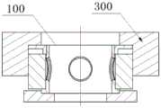
步骤5,如图3所示,压紧模具300压紧顶盖4顶部,采用激光焊将固定柱1与顶盖4激光焊固定。采用压紧模具300压紧顶盖4,防止激光焊接后吸气剂松动,产生响声。激光焊均布四点固定,然后再焊成链,每个链8点,重叠率50%左右,激光焊焊接参数为脉宽8ms,能量600J。压紧模具300,一般采用不锈钢等材料,在避开焊缝焊接位置,能够将吸气剂7与底座8压紧,保证焊接过程中压盖与吸气剂不会松动或倾斜。
至此,已经结合附图对本公开实施例进行了详细描述。需要说明的是,在附图或说明书正文中,未绘示或描述的实现方式,均为所属技术领域中普通技术人员所知的形式,并未进行详细说明。此外,上述对各元件和方法的定义并不仅限于实施例中提到的各种具体结构、形状或方式,本领域普通技术人员可对其进行简单地更改或替换。So far, the embodiments of the present disclosure have been described in detail with reference to the accompanying drawings. It should be noted that, in the accompanying drawings or in the text of the specification, implementations that are not shown or described are forms known to those of ordinary skill in the art, and are not described in detail. In addition, the above definitions of each element and method are not limited to the various specific structures, shapes or methods mentioned in the embodiments, and those skilled in the art can easily modify or replace them.
依据以上描述,本领域技术人员应当对本公开用于空间行波管的吸气剂固定结构有了清楚的认识。According to the above description, those skilled in the art should have a clear understanding of the getter fixing structure used in the space traveling wave tube of the present disclosure.
综上所述,本公开提供一种用于空间行波管的吸气剂固定结构,同时满足行波管耐温度冲击、耐力学振动的要求;和行波管烘排前吸气剂不激活,吸气剂表外露面积大,固定结构小型化的要求。在微波电真空器件技术领域中,需要在行波管内部固定吸气剂以维持稳定工作需要的真空度的应用有重要意义。To sum up, the present disclosure provides a getter fixing structure for a space traveling wave tube, which meets the requirements of temperature shock resistance and mechanical vibration resistance of the traveling wave tube at the same time; and the getter is not activated before the traveling wave tube is dried , The exposed area of the getter surface is large, and the requirement of miniaturization of the fixed structure. In the technical field of microwave electric vacuum devices, it is of great significance to fix the getter inside the traveling wave tube to maintain the vacuum required for stable operation.
还需要说明的是,实施例中提到的方向用语,例如“上”、“下”、“前”、“后”、“左”、“右”等,仅是参考附图的方向,并非用来限制本公开的保护范围。贯穿附图,相同的元素由相同或相近的附图标记来表示。在可能导致对本公开的理解造成混淆时,将省略常规结构或构造。It should also be noted that the directional terms mentioned in the embodiments, such as "up", "down", "front", "back", "left", "right", etc., are only referring to the directions of the drawings, not Used to limit the protection scope of this disclosure. Throughout the drawings, the same elements are indicated by the same or similar reference numerals. Conventional structures or constructions are omitted when they may obscure the understanding of the present disclosure.
并且图中各部件的形状和尺寸不反映真实大小和比例,而仅示意本公开实施例的内容。另外,在权利要求中,不应将位于括号之间的任何参考符号构造成对权利要求的限制。And the shape and size of each component in the figure do not reflect the actual size and proportion, but only illustrate the content of the embodiment of the present disclosure. Furthermore, in the claims, any reference signs placed between parentheses shall not be construed as limiting the claim.
再者,单词“包含”不排除存在未列在权利要求中的元件或步骤。位于元件之前的单词“一”或“一个”不排除存在多个这样的元件。Furthermore, the word "comprising" does not exclude the presence of elements or steps not listed in a claim. The word "a" or "an" preceding an element does not exclude the presence of a plurality of such elements.
说明书与权利要求中所使用的序数例如“第一”、“第二”、“第三”等的用词,以修饰相应的元件,其本身并不意味着该元件有任何的序数,也不代表某一元件与另一元件的顺序、或是制造方法上的顺序,该些序数的使用仅用来使具有某命名的一元件得以和另一具有相同命名的元件能做出清楚区分。Words such as "first", "second", "third" and the like used in the description and claims to modify the corresponding elements do not in themselves mean that the elements have any ordinal numbers, nor The use of these ordinal numbers to represent the sequence of an element with respect to another element, or the order of manufacturing methods, is only used to clearly distinguish one element with a certain designation from another element with the same designation.
此外,除非特别描述或必须依序发生的步骤,上述步骤的顺序并无限制于以上所列,且可根据所需设计而变化或重新安排。并且上述实施例可基于设计及可靠度的考虑,彼此混合搭配使用或与其他实施例混合搭配使用,即不同实施例中的技术特征可以自由组合形成更多的实施例。In addition, unless specifically described or steps that must occur sequentially, the order of the above steps is not limited to that listed above and may be changed or rearranged according to the desired design. Moreover, the above-mentioned embodiments can be mixed and matched with each other or with other embodiments based on design and reliability considerations, that is, technical features in different embodiments can be freely combined to form more embodiments.
类似地,应当理解,为了精简本公开并帮助理解各个公开方面中的一个或多个,在上面对本公开的示例性实施例的描述中,本公开的各个特征有时被一起分组到单个实施例、图、或者对其的描述中。然而,并不应将该公开的方法解释成反映如下意图:即所要求保护的本公开要求比在每个权利要求中所明确记载的特征更多的特征。更确切地说,如下面的权利要求书所反映的那样,公开方面在于少于前面公开的单个实施例的所有特征。因此,遵循具体实施方式的权利要求书由此明确地并入该具体实施方式,其中每个权利要求本身都作为本公开的单独实施例。Similarly, it should be appreciated that in the above description of exemplary embodiments of the disclosure, in order to streamline the disclosure and to facilitate an understanding of one or more of the various disclosed aspects, various features of the disclosure are sometimes grouped together into a single embodiment, figure, or its description. This method of disclosure, however, is not to be interpreted as reflecting an intention that the claimed disclosure requires more features than are expressly recited in each claim. Rather, as the following claims reflect, disclosed aspects lie in less than all features of a single foregoing disclosed embodiment. Thus the claims following the Detailed Description are hereby expressly incorporated into this Detailed Description, with each claim standing on its own as a separate embodiment of this disclosure.
以上所述的具体实施例,对本公开的目的、技术方案和有益效果进行了进一步详细说明,所应理解的是,以上所述仅为本公开的具体实施例而已,并不用于限制本公开,凡在本公开的精神和原则之内,所做的任何修改、等同替换、改进等,均应包含在本公开的保护范围之内。The specific embodiments described above further describe the purpose, technical solutions and beneficial effects of the present disclosure in detail. It should be understood that the above descriptions are only specific embodiments of the present disclosure, and are not intended to limit the present disclosure. Any modifications, equivalent replacements, improvements, etc. made within the spirit and principles of the present disclosure shall be included within the protection scope of the present disclosure.
Claims (6)
Translated fromChinesePriority Applications (1)
| Application Number | Priority Date | Filing Date | Title |
|---|---|---|---|
| CN202010491894.4ACN111599661B (en) | 2020-06-02 | 2020-06-02 | Getter Fixed Structure for Space Traveling Wave Tube |
Applications Claiming Priority (1)
| Application Number | Priority Date | Filing Date | Title |
|---|---|---|---|
| CN202010491894.4ACN111599661B (en) | 2020-06-02 | 2020-06-02 | Getter Fixed Structure for Space Traveling Wave Tube |
Publications (2)
| Publication Number | Publication Date |
|---|---|
| CN111599661A CN111599661A (en) | 2020-08-28 |
| CN111599661Btrue CN111599661B (en) | 2023-05-26 |
Family
ID=72185986
Family Applications (1)
| Application Number | Title | Priority Date | Filing Date |
|---|---|---|---|
| CN202010491894.4AActiveCN111599661B (en) | 2020-06-02 | 2020-06-02 | Getter Fixed Structure for Space Traveling Wave Tube |
Country Status (1)
| Country | Link |
|---|---|
| CN (1) | CN111599661B (en) |
Citations (26)
| Publication number | Priority date | Publication date | Assignee | Title |
|---|---|---|---|---|
| US2082268A (en)* | 1935-03-13 | 1937-06-01 | Farnsworth Television Inc | Getter cartridge |
| US2824640A (en)* | 1952-09-27 | 1958-02-25 | Porta Paolo Della | Getter containers and a method of manufacturing such containers |
| US3953755A (en)* | 1973-11-15 | 1976-04-27 | U.S. Philips Corporation | High pressure gas discharge lamp including a hydrogen getter |
| US4101247A (en)* | 1976-05-12 | 1978-07-18 | S.A.E.S. Getters S.P.A. | Getter device with improved support member |
| GB1523898A (en)* | 1974-09-26 | 1978-09-06 | Philips Electronic Associated | Getter holder |
| US4127361A (en)* | 1976-11-29 | 1978-11-28 | S.A.E.S. Getters S.P.A. | Air-bakeable water-proof getter device and method of manufacturing same |
| US4145162A (en)* | 1976-12-06 | 1979-03-20 | S.A.E.S. Getters S.P.A. | Getter device and method of use |
| JPS60112229A (en)* | 1983-11-19 | 1985-06-18 | Sony Corp | Getter supporting structure body of cathode ray tube |
| JPS63264853A (en)* | 1988-02-22 | 1988-11-01 | Sony Corp | Getter support body structure for cathode-ray tube |
| JPH05205662A (en)* | 1992-01-23 | 1993-08-13 | Toshiba Corp | Non-evaporable getter |
| JPH07105877A (en)* | 1993-10-01 | 1995-04-21 | Matsushita Electric Ind Co Ltd | Image display device |
| JPH07312187A (en)* | 1994-05-14 | 1995-11-28 | Sony Corp | Getter vessel |
| JPH08250047A (en)* | 1995-03-13 | 1996-09-27 | Matsushita Electric Ind Co Ltd | Image display device manufacturing method |
| JPH10188829A (en)* | 1996-12-20 | 1998-07-21 | Sony Corp | Getter assembly |
| US5827048A (en)* | 1995-10-31 | 1998-10-27 | Futaba Denshi Kogyo K.K. | Getter support |
| KR19990019645A (en)* | 1997-08-29 | 1999-03-15 | 김영남 | Evaporable Getters with Anti-Oxide Films for Field Emission Display Devices |
| US5977706A (en)* | 1996-12-12 | 1999-11-02 | Candescent Technologies Corporation | Multi-compartment getter-containing flat-panel device |
| JP2000021320A (en)* | 1998-07-03 | 2000-01-21 | Hitachi Ltd | Display discharge tube |
| JP2001167695A (en)* | 1999-12-09 | 2001-06-22 | Mitsubishi Electric Corp | Getter device and cathode ray tube |
| JP2005074504A (en)* | 2003-09-03 | 2005-03-24 | Dainippon Printing Co Ltd | Fixed jig |
| CN101295612A (en)* | 2008-06-06 | 2008-10-29 | 北京有色金属研究总院 | Production method of ring-shaped vacuum suction element without metal bottom bracket |
| CN201191088Y (en)* | 2008-02-20 | 2009-02-04 | 黄鸣 | Fixing bracket of getter |
| JP2014182911A (en)* | 2013-03-19 | 2014-09-29 | Ushio Inc | Short-arc type discharge lamp |
| CN104291707A (en)* | 2013-07-17 | 2015-01-21 | 戴长虹 | Sealing arrangement structure of getter in vacuum glass and manufacturing method thereof |
| CN207365431U (en)* | 2017-07-27 | 2018-05-15 | 南京诚远太阳能科技有限公司 | A kind of composite getter for metal direct connection solar energy vacuum tube |
| CN108119329A (en)* | 2017-12-20 | 2018-06-05 | 南京华东电子真空材料有限公司 | A kind of compact-sized sundstrand pump of big pumping speed |
- 2020
- 2020-06-02CNCN202010491894.4Apatent/CN111599661B/enactiveActive
Patent Citations (26)
| Publication number | Priority date | Publication date | Assignee | Title |
|---|---|---|---|---|
| US2082268A (en)* | 1935-03-13 | 1937-06-01 | Farnsworth Television Inc | Getter cartridge |
| US2824640A (en)* | 1952-09-27 | 1958-02-25 | Porta Paolo Della | Getter containers and a method of manufacturing such containers |
| US3953755A (en)* | 1973-11-15 | 1976-04-27 | U.S. Philips Corporation | High pressure gas discharge lamp including a hydrogen getter |
| GB1523898A (en)* | 1974-09-26 | 1978-09-06 | Philips Electronic Associated | Getter holder |
| US4101247A (en)* | 1976-05-12 | 1978-07-18 | S.A.E.S. Getters S.P.A. | Getter device with improved support member |
| US4127361A (en)* | 1976-11-29 | 1978-11-28 | S.A.E.S. Getters S.P.A. | Air-bakeable water-proof getter device and method of manufacturing same |
| US4145162A (en)* | 1976-12-06 | 1979-03-20 | S.A.E.S. Getters S.P.A. | Getter device and method of use |
| JPS60112229A (en)* | 1983-11-19 | 1985-06-18 | Sony Corp | Getter supporting structure body of cathode ray tube |
| JPS63264853A (en)* | 1988-02-22 | 1988-11-01 | Sony Corp | Getter support body structure for cathode-ray tube |
| JPH05205662A (en)* | 1992-01-23 | 1993-08-13 | Toshiba Corp | Non-evaporable getter |
| JPH07105877A (en)* | 1993-10-01 | 1995-04-21 | Matsushita Electric Ind Co Ltd | Image display device |
| JPH07312187A (en)* | 1994-05-14 | 1995-11-28 | Sony Corp | Getter vessel |
| JPH08250047A (en)* | 1995-03-13 | 1996-09-27 | Matsushita Electric Ind Co Ltd | Image display device manufacturing method |
| US5827048A (en)* | 1995-10-31 | 1998-10-27 | Futaba Denshi Kogyo K.K. | Getter support |
| US5977706A (en)* | 1996-12-12 | 1999-11-02 | Candescent Technologies Corporation | Multi-compartment getter-containing flat-panel device |
| JPH10188829A (en)* | 1996-12-20 | 1998-07-21 | Sony Corp | Getter assembly |
| KR19990019645A (en)* | 1997-08-29 | 1999-03-15 | 김영남 | Evaporable Getters with Anti-Oxide Films for Field Emission Display Devices |
| JP2000021320A (en)* | 1998-07-03 | 2000-01-21 | Hitachi Ltd | Display discharge tube |
| JP2001167695A (en)* | 1999-12-09 | 2001-06-22 | Mitsubishi Electric Corp | Getter device and cathode ray tube |
| JP2005074504A (en)* | 2003-09-03 | 2005-03-24 | Dainippon Printing Co Ltd | Fixed jig |
| CN201191088Y (en)* | 2008-02-20 | 2009-02-04 | 黄鸣 | Fixing bracket of getter |
| CN101295612A (en)* | 2008-06-06 | 2008-10-29 | 北京有色金属研究总院 | Production method of ring-shaped vacuum suction element without metal bottom bracket |
| JP2014182911A (en)* | 2013-03-19 | 2014-09-29 | Ushio Inc | Short-arc type discharge lamp |
| CN104291707A (en)* | 2013-07-17 | 2015-01-21 | 戴长虹 | Sealing arrangement structure of getter in vacuum glass and manufacturing method thereof |
| CN207365431U (en)* | 2017-07-27 | 2018-05-15 | 南京诚远太阳能科技有限公司 | A kind of composite getter for metal direct connection solar energy vacuum tube |
| CN108119329A (en)* | 2017-12-20 | 2018-06-05 | 南京华东电子真空材料有限公司 | A kind of compact-sized sundstrand pump of big pumping speed |
Also Published As
| Publication number | Publication date |
|---|---|
| CN111599661A (en) | 2020-08-28 |
Similar Documents
| Publication | Publication Date | Title |
|---|---|---|
| CN103762135A (en) | Heat shield component of hollow cathode heater | |
| JP5893350B2 (en) | Radiation tube and radiation generator using the same | |
| JPS583338B2 (en) | magnetron | |
| CN111599661B (en) | Getter Fixed Structure for Space Traveling Wave Tube | |
| CN215138368U (en) | Self-vacuum composite getter convenient to use | |
| CN114147357B (en) | Output window for traveling wave tube and preparation method thereof | |
| CN102103960B (en) | Outer cylinder side opening type multistage depressed collector component and manufacturing method thereof | |
| CN105810536A (en) | Magnetron employing combined cold cathode head and production method of cold cathode body | |
| CN102324355B (en) | Travelling wave tube spiral line clamping device and assembly process thereof | |
| JP3996442B2 (en) | Electron gun | |
| CN114284121A (en) | Electron gun for traveling wave tube and preparation method thereof | |
| JP2002025446A (en) | Manufacturing method of x-ray tube | |
| JP2009516344A (en) | Improvement of electrodes and electrode parts | |
| CN203746784U (en) | Helix travelling wave tube cathode structure | |
| JP2000294192A (en) | Double discharge tube and its manufacture | |
| CN101890328A (en) | Non-evaporable air-absorbing agent and application thereof | |
| CN203631480U (en) | Cathode structure of broadband millimeter-wave travelling wave tube | |
| CN112563096A (en) | Medical X-ray tube with large thermal capacity | |
| JP2827678B2 (en) | Microwave tube | |
| CN221668767U (en) | Industrial glass X-ray tube | |
| CN203277310U (en) | Integrated assembly structure of getter and anode | |
| JPS5854769Y2 (en) | electron tube | |
| CN2669361Y (en) | Getter device for projection tube electronic gun | |
| KR102334309B1 (en) | Staionary anode type X-ray Tube to have non-evaporable getter | |
| JPH05343031A (en) | Discharge tube and manufacture thereof |
Legal Events
| Date | Code | Title | Description |
|---|---|---|---|
| PB01 | Publication | ||
| PB01 | Publication | ||
| SE01 | Entry into force of request for substantive examination | ||
| SE01 | Entry into force of request for substantive examination | ||
| GR01 | Patent grant | ||
| GR01 | Patent grant |