CN111594776A - Be applied to light structure of vanity mirror - Google Patents
Be applied to light structure of vanity mirrorDownload PDFInfo
- Publication number
- CN111594776A CN111594776ACN202010172578.0ACN202010172578ACN111594776ACN 111594776 ACN111594776 ACN 111594776ACN 202010172578 ACN202010172578 ACN 202010172578ACN 111594776 ACN111594776 ACN 111594776A
- Authority
- CN
- China
- Prior art keywords
- light
- reflective film
- guide column
- light guide
- cosmetic mirror
- Prior art date
- Legal status (The legal status is an assumption and is not a legal conclusion. Google has not performed a legal analysis and makes no representation as to the accuracy of the status listed.)
- Pending
Links
- 239000002537cosmeticSubstances0.000claimsabstractdescription22
- 239000012528membraneSubstances0.000claims8
- 230000007547defectEffects0.000abstract1
- 238000000265homogenisationMethods0.000abstract1
- 238000000034methodMethods0.000description15
- 238000013461designMethods0.000description3
- 238000009434installationMethods0.000description3
- 238000010586diagramMethods0.000description2
- 230000001795light effectEffects0.000description2
- 230000009471actionEffects0.000description1
- 239000011324beadSubstances0.000description1
- 230000009286beneficial effectEffects0.000description1
- 230000007812deficiencyEffects0.000description1
- 238000011161developmentMethods0.000description1
- 230000017525heat dissipationEffects0.000description1
- 230000003993interactionEffects0.000description1
- 238000012986modificationMethods0.000description1
- 230000004048modificationEffects0.000description1
- 238000013021overheatingMethods0.000description1
- 230000008569processEffects0.000description1
Images

Classifications
- F—MECHANICAL ENGINEERING; LIGHTING; HEATING; WEAPONS; BLASTING
- F21—LIGHTING
- F21S—NON-PORTABLE LIGHTING DEVICES; SYSTEMS THEREOF; VEHICLE LIGHTING DEVICES SPECIALLY ADAPTED FOR VEHICLE EXTERIORS
- F21S8/00—Lighting devices intended for fixed installation
- A—HUMAN NECESSITIES
- A47—FURNITURE; DOMESTIC ARTICLES OR APPLIANCES; COFFEE MILLS; SPICE MILLS; SUCTION CLEANERS IN GENERAL
- A47G—HOUSEHOLD OR TABLE EQUIPMENT
- A47G1/00—Mirrors; Picture frames or the like, e.g. provided with heating, lighting or ventilating means
- A47G1/02—Mirrors used as equipment
- F—MECHANICAL ENGINEERING; LIGHTING; HEATING; WEAPONS; BLASTING
- F21—LIGHTING
- F21V—FUNCTIONAL FEATURES OR DETAILS OF LIGHTING DEVICES OR SYSTEMS THEREOF; STRUCTURAL COMBINATIONS OF LIGHTING DEVICES WITH OTHER ARTICLES, NOT OTHERWISE PROVIDED FOR
- F21V5/00—Refractors for light sources
- F21V5/002—Refractors for light sources using microoptical elements for redirecting or diffusing light
- F—MECHANICAL ENGINEERING; LIGHTING; HEATING; WEAPONS; BLASTING
- F21—LIGHTING
- F21V—FUNCTIONAL FEATURES OR DETAILS OF LIGHTING DEVICES OR SYSTEMS THEREOF; STRUCTURAL COMBINATIONS OF LIGHTING DEVICES WITH OTHER ARTICLES, NOT OTHERWISE PROVIDED FOR
- F21V7/00—Reflectors for light sources
- F21V7/22—Reflectors for light sources characterised by materials, surface treatments or coatings, e.g. dichroic reflectors
- F21V7/28—Reflectors for light sources characterised by materials, surface treatments or coatings, e.g. dichroic reflectors characterised by coatings
- F—MECHANICAL ENGINEERING; LIGHTING; HEATING; WEAPONS; BLASTING
- F21—LIGHTING
- F21V—FUNCTIONAL FEATURES OR DETAILS OF LIGHTING DEVICES OR SYSTEMS THEREOF; STRUCTURAL COMBINATIONS OF LIGHTING DEVICES WITH OTHER ARTICLES, NOT OTHERWISE PROVIDED FOR
- F21V2200/00—Use of light guides, e.g. fibre optic devices, in lighting devices or systems
- F—MECHANICAL ENGINEERING; LIGHTING; HEATING; WEAPONS; BLASTING
- F21—LIGHTING
- F21W—INDEXING SCHEME ASSOCIATED WITH SUBCLASSES F21K, F21L, F21S and F21V, RELATING TO USES OR APPLICATIONS OF LIGHTING DEVICES OR SYSTEMS
- F21W2131/00—Use or application of lighting devices or systems not provided for in codes F21W2102/00-F21W2121/00
- F21W2131/30—Lighting for domestic or personal use
- F21W2131/302—Lighting for domestic or personal use for mirrors
Landscapes
- Engineering & Computer Science (AREA)
- General Engineering & Computer Science (AREA)
- Planar Illumination Modules (AREA)
Abstract
Description
Translated fromChinese技术领域technical field
本发明涉及化妆镜技术等领域,具体的说,是应用于化妆镜的灯光结构。The invention relates to the fields of cosmetic mirror technology and the like, in particular to a lighting structure applied to a cosmetic mirror.
背景技术Background technique
化妆镜为镜子的一种分类,一般体积较小,放在梳妆台使用,市面上常见的化妆镜有圆形、方形等,随着其作用与不同的的场所,其设计更具功能化,而随着应用场景的不同,在其上设计的功能点越来越多,比如在黑暗环境中使用,比如现在随着直播技术的发展,带有补光效果或能够形成光亮的化妆镜更是大行其道,而现有带补光效果的化妆镜,由于其光源结构的设置不尽理想原因,存在发出的光质量差或光线不均匀等问题。Cosmetic mirrors are a category of mirrors. They are generally small in size and are used on dressing tables. Common cosmetic mirrors on the market are round, square, etc. With their functions and different places, their designs are more functional. With different application scenarios, more and more function points are designed on it, such as use in dark environments. For example, with the development of live broadcast technology, makeup mirrors with fill light effects or that can form bright are even more However, the existing cosmetic mirrors with supplementary light effect have problems such as poor light quality or uneven light due to the unsatisfactory setting of the light source structure.
发明内容SUMMARY OF THE INVENTION
本发明的目的在于设计出应用于化妆镜的灯光结构,能够解决现有技术中带有光源的化妆镜其光源质量差或光线不均匀的不足之处,其能够实现光线均匀化且有效提升光线质量。The purpose of the present invention is to design a lighting structure applied to a cosmetic mirror, which can solve the disadvantages of poor light source quality or uneven light in the cosmetic mirror with a light source in the prior art, and can achieve uniform light and effectively improve light. quality.
本发明通过下述技术方案实现:应用于化妆镜的灯光结构,包括均光板、第二反光膜、导光柱、第一反光膜、支撑件及灯带,在支撑件上设置第一反光膜,在第一反光膜上设置一圈导光柱,在导光柱远第一反光膜侧设置第二反光膜,在导光柱和第二反光膜上设置均光板,灯带设置在支撑件上且与第一反光膜的内圈间隙配合。The present invention is achieved through the following technical solutions: a lighting structure applied to a cosmetic mirror includes a light homogenizer, a second reflective film, a light guide column, a first reflective film, a support and a light strip, and the support is provided with a first reflective film, A circle of light guide columns is arranged on the first reflective film, a second reflective film is arranged on the side of the light guide column far from the first reflective film, a light homogenizer is arranged on the light guide column and the second reflective film, and the light strip is arranged on the support and is connected with the first reflective film. An inner ring of the reflective film is gap-fitted.
优选的,灯带位于导光柱和第一反光膜之间。Preferably, the light strip is located between the light guide column and the first reflective film.
进一步的为实现本发明,特别采用下述设置方式:所述第二反光膜的外径小于导光柱的外径,且第二反光膜与导光柱同心设置。Further, in order to realize the present invention, the following arrangement is particularly adopted: the outer diameter of the second light-reflecting film is smaller than the outer diameter of the light-guiding column, and the second light-reflecting film and the light-guiding column are arranged concentrically.
进一步的为实现本发明,特别采用下述设置方式:所述导光柱的内圈与灯带的外圈间隙配合。Further, in order to realize the present invention, the following setting method is particularly adopted: the inner ring of the light guide column is in clearance fit with the outer ring of the light strip.
进一步的为实现本发明,特别采用下述设置方式:所述均光板上形成有两个相交面,且其中一个相交面与第二反光膜和导光柱相接触,且另一个相交面与导光柱的内圈相接触。Further, in order to realize the present invention, the following setting method is specially adopted: two intersecting surfaces are formed on the homogenizing plate, and one of the intersecting surfaces is in contact with the second reflective film and the light guide column, and the other intersecting surface is in contact with the light guide column. contact with the inner ring.
进一步的为实现本发明,特别采用下述设置方式:所述均光板可拆卸设置在支撑件上。Further, in order to realize the present invention, the following setting method is particularly adopted: the homogenizing plate is detachably arranged on the support member.
进一步的为实现本发明,特别采用下述设置方式:在所述均光板的远支撑件的一面还设置有镜面。Further, in order to realize the present invention, the following setting method is particularly adopted: a mirror surface is also arranged on the side of the far support member of the homogenizing plate.
进一步的为实现本发明,特别采用下述设置方式:所述第二反光膜和第一反光膜皆为圈状平面,所述镜面为反光镜面。Further, in order to realize the present invention, the following arrangement is particularly adopted: the second reflective film and the first reflective film are both circular planes, and the mirror surface is a reflective mirror surface.
进一步的为实现本发明,特别采用下述设置方式:所述均光板、第二反光膜、导光柱、第一反光膜、支撑件及灯带呈同心结构设置。Further, in order to realize the present invention, the following arrangement is particularly adopted: the homogenizing plate, the second reflective film, the light guide column, the first reflective film, the support and the light strip are arranged in a concentric structure.
进一步的为实现本发明,特别采用下述设置方式:所述均光板、第二反光膜、导光柱、第一反光膜、支撑件及灯带皆为圆形或椭圆形或方形等。Further, in order to realize the present invention, the following arrangement is particularly adopted: the homogenizing plate, the second reflective film, the light guide column, the first reflective film, the support and the light strip are all round, oval or square.
本发明与现有技术相比,具有以下优点及有益效果:Compared with the prior art, the present invention has the following advantages and beneficial effects:
(1)本发明能够解决现有技术中带有光源的化妆镜其光源质量差或光线不均匀的不足之处,其能够实现光线均匀化且有效提升光线质量。(1) The present invention can solve the deficiencies of poor quality of light source or uneven light of the cosmetic mirror with light source in the prior art, and can realize the uniformity of light and effectively improve the quality of light.
(2)本发明的灯带上灯珠均匀排列,能够带来均匀的光线;能够实现均匀的散热,不会出现局部过热的现象。(2) The lamp beads on the lamp strip of the present invention are evenly arranged, which can bring uniform light; can achieve uniform heat dissipation, and will not cause local overheating.
(3)本发明所述导光柱的应用,不需要在灯光结构中再做渐变光结构,从而降低了工艺的复杂度。(3) The application of the light guide column of the present invention does not require a gradient light structure in the light structure, thereby reducing the complexity of the process.
(4)本发明采用双层反光膜结构设计,减少光线损耗。(4) The present invention adopts a double-layer reflective film structure design to reduce light loss.
附图说明Description of drawings
图1为本发明结构示意图(爆炸图)。Figure 1 is a schematic structural diagram (exploded view) of the present invention.
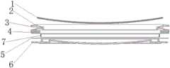
图2为本发明结构示意图(剖视图)。FIG. 2 is a schematic structural diagram (cross-sectional view) of the present invention.
其中,1-镜面、2-均光板、3-第二反光膜、4-导光柱、5-第一反光膜、6-支撑件、7-灯带。Among them, 1-mirror surface, 2-homogenizing plate, 3-second reflective film, 4-light guide column, 5-first reflective film, 6-support member, 7-light strip.
具体实施方式Detailed ways
下面结合实施例对本发明作进一步地详细说明,但本发明的实施方式不限于此。The present invention will be further described in detail below with reference to the examples, but the embodiments of the present invention are not limited thereto.
为使本发明实施方式的目的、技术方案和优点更加清楚,下面将结合本发明实施方式中的附图,对本发明实施方式中的技术方案进行清楚、完整地描述,显然,所描述的实施方式是本发明一部分实施方式,而不是全部的实施方式。基于本发明中的实施方式,本领域普通技术人员在没有作出创造性劳动前提下所获得的所有其他实施方式,的属于本发明保护的范围。因此,以下对在附图中提供的本发明的实施方式的详细描述并非旨在限制要求保护的本发明的范围,而是仅仅表示本发明的选定实施方式。基于本发明中的实施方式,本领域普通技术人员在没有作出创造性劳动前提下所获得的所有其他实施方式,的属于本发明保护的范围。In order to make the purposes, technical solutions and advantages of the embodiments of the present invention clearer, the technical solutions in the embodiments of the present invention will be clearly and completely described below with reference to the accompanying drawings in the embodiments of the present invention. Obviously, the described embodiments These are some embodiments of the present invention, but not all of them. Based on the embodiments of the present invention, all other embodiments obtained by those of ordinary skill in the art without creative work fall within the protection scope of the present invention. Accordingly, the following detailed description of the embodiments of the invention provided in the accompanying drawings is not intended to limit the scope of the invention as claimed, but is merely representative of selected embodiments of the invention. Based on the embodiments of the present invention, all other embodiments obtained by those of ordinary skill in the art without creative work fall within the protection scope of the present invention.
在本发明的描述中,需要理解的是,术语“中心”、“纵向”、“横 向”、“长度”、“宽度”、“厚度”、“上”、“下”、“前”、“后”、“左”、“右”、 “竖直”、“水平”、“顶”、“底”、“内”、“外”、“顺时针”、“逆时针”等指示的方位或位置关系为基于附图所示的方位或位置关系,仅是为了便于描述本发明和简化描述,而不是指示或暗示所指的设备或元件必须具有特定的方位、以特定的方位构造和操作,因此不能理解为对本发明的限制。In the description of the present invention, it should be understood that the terms "center", "longitudinal", "lateral", "length", "width", "thickness", "upper", "lower", "front", " Rear, Left, Right, Vertical, Horizontal, Top, Bottom, Inner, Outer, Clockwise, Counterclockwise, etc. The positional relationship is based on the orientation or positional relationship shown in the drawings, which is only for the convenience of describing the present invention and simplifying the description, rather than indicating or implying that the referred device or element must have a specific orientation, be constructed and operated in a specific orientation, Therefore, it should not be construed as a limitation of the present invention.
此外,术语“第一”、“第二”仅用于描述目的,而不能理解为指示或暗示相对重要性或者隐含指明所指示的技术特征的数量。由此,限定有“第一”、“第二”的特征可以明示或者隐含地包括一个或者更多个该特征。在本发明的描述中,“多个”的含义是两个或两个以上,除非另有明确具体的限定。In addition, the terms "first" and "second" are only used for descriptive purposes, and should not be construed as indicating or implying relative importance or implying the number of indicated technical features. Thus, a feature defined as "first" or "second" may expressly or implicitly include one or more of that feature. In the description of the present invention, "plurality" means two or more, unless otherwise expressly and specifically defined.
在本发明中,除非另有明确的规定和限定,术语“安装”、“相连”、“连接”、“固定”等术语应做广义理解,例如,可以是固定连接,也 可以是可拆卸连接,或成一体;可以是机械连接,也可以是电连接;可以是直接相连,也可以通过中间媒介间接相连,可以是两个元件内部的连通或两个元件的相互作用关系。对于本领域的普通技术人员而言,可以根据具体情况理解上述术语在本发明中的具体含义。In the present invention, unless otherwise expressly specified and limited, the terms "installed", "connected", "connected", "fixed" and other terms should be understood in a broad sense, for example, it may be a fixed connection or a detachable connection , or integrated; it can be a mechanical connection or an electrical connection; it can be a direct connection or an indirect connection through an intermediate medium, and it can be the internal connection of the two elements or the interaction relationship between the two elements. For those of ordinary skill in the art, the specific meanings of the above terms in the present invention can be understood according to specific situations.
在本发明中,除非另有明确的规定和限定,第一特征在第二特征之“上”或之“下”可以包括第一和第二特征直接接触,也可以包括第一和第二特征不是直接接触而是通过它们之间的另外的特征接触。而且,第一特征在第二特征“之上”、“上方”和“上面”包括第一特征在第二特征正上方和斜上方,或仅仅表示第一特征水平高度高于第二特征。第一特征在第二特征“之下”、“下方”和“下面”包括第一特征在第二特征正下方和斜下方,或仅仅表示第一特征水平高度小于第二特征。In the present invention, unless otherwise expressly specified and limited, a first feature "on" or "under" a second feature may include the first and second features in direct contact, or may include the first and second features Not directly but through additional features between them. Also, the first feature being "above", "over" and "above" the second feature includes the first feature being directly above and obliquely above the second feature, or simply means that the first feature is level higher than the second feature. The first feature is "below", "below" and "below" the second feature includes the first feature being directly below and diagonally below the second feature, or simply means that the first feature has a lower level than the second feature.
实施例1:Example 1:
本发明提出了应用于化妆镜的灯光结构,能够解决现有技术中带有光源的化妆镜其光源质量差或光线不均匀的不足之处,其能够实现光线均匀化且有效提升光线质量,如图1~图2所示,特别采用下述设置方式:包括均光板2、第二反光膜3、导光柱4、第一反光膜5、支撑件6及灯带7,在支撑件6上设置第一反光膜5,在第一反光膜5上设置一圈导光柱4,在导光柱4远第一反光膜5侧设置第二反光膜3,在导光柱4和第二反光膜3上设置均光板2,灯带7设置在支撑件6上且与第一反光膜5的内圈间隙配合。The present invention proposes a lighting structure applied to a cosmetic mirror, which can solve the disadvantages of poor light source quality or uneven light in the cosmetic mirror with a light source in the prior art, and can realize uniform light and effectively improve light quality, such as As shown in FIG. 1 to FIG. 2 , the following setting method is particularly adopted: including a light
作为优选的设置方案,该灯光结构主要由均光板2、第二反光膜3、导光柱4、第一反光膜5、支撑件6及灯带7所构成,其中,支撑件6作为主体支撑结构使用,作为光源的灯带7支撑设置在支撑件6上,在支撑件6的平面上设置(敷设或粘贴等)有一圈第一反光膜5,该反光膜为平面圈状结构,即内圈为中空,外圈为反光结构,用于反射侧漏的灯光,第一反光膜5采用整面或环面,且外圈层大于灯带7的外圈层;在第一反光膜5上远离支撑件6的一面设置(优选的采用双面胶粘贴)一圈导光柱4,用于将光线均匀分散;在导光柱4远第一反光膜5侧设置第二反光膜3,该反光膜亦为平面圈状结构,即内圈为中空,外圈为反光结构,即将导光柱4设置在第一反光膜5和第二反光膜3之间,第二反光膜3的设置用于改善灯带内侧的阴影;在导光柱4和第二反光膜3上设置均光板2,即在同一平面侧均光板2皆与导光柱4和第二反光膜3相接触,用于柔和光线;当第一反光膜5采用环状的反光膜时,灯带7的外圈与第一反光膜5的内圈间隙配合,优选的,灯带7位于导光柱4和第一反光膜5之间。As a preferred arrangement, the lighting structure is mainly composed of a
在使用时,当与控制电路相连接时,能够在控制电路的作用下,使得灯带进行发光,在本申请所要保护的技术方案中,控制电路可为现有灯电路的控制电路,亦可为重新设计的电路,在本申请中不做保护,因此,申请人液不对所涉及的电路做具体的介绍。In use, when connected to the control circuit, the light strip can be made to emit light under the action of the control circuit. In the technical solution to be protected by this application, the control circuit can be the control circuit of the existing lamp circuit, or Circuits designed for redesign are not protected in this application, therefore, the applicant does not make a specific introduction to the circuits involved.
实施例2:Example 2:
本实施例是在上述实施例的基础上进一步优化,与前述实施方案相同部分在此将不再赘述,进一步的为实现本发明,如图1、图2所示,特别采用下述设置方式:所述第二反光膜3的外径小于导光柱4的外径,且第二反光膜3与导光柱4同心设置。This embodiment is further optimized on the basis of the above-mentioned embodiment, and the same parts as the previous embodiment will not be repeated here. Further, in order to realize the present invention, as shown in Figure 1 and Figure 2, the following setting methods are specially adopted: The outer diameter of the second light-reflecting
作为优选的设置方案,第二反光膜3的外径小于导光柱4的外径,且两者在设置时采用同心的方式设在 一起,具体设置时可采用胶粘的方式将第二反光膜3设在导光柱4上。As a preferred arrangement solution, the outer diameter of the second
实施例3:Example 3:
本实施例是在上述任一实施例的基础上进一步优化,与前述技术方案相同部分在此将不再赘述,进一步的为实现本发明,如图1、图2所示,特别采用下述设置方式:所述导光柱4的内圈与灯带7的外圈间隙配合。This embodiment is further optimized on the basis of any of the above-mentioned embodiments, and the same parts as the above-mentioned technical solutions will not be repeated here. In order to further realize the present invention, as shown in FIG. 1 and FIG. 2 , the following settings are specially adopted Method: The inner ring of the
作为优选的设置方案,导光柱4套在灯带7的外侧。As a preferred arrangement solution, the
实施例4:Example 4:
本实施例是在上述任一实施例的基础上进一步优化,与前述技术方案相同部分在此将不再赘述,进一步的为实现本发明,如图1、图2所示,进一步的为实现本发明,特别采用下述设置方式:所述均光板2上形成有两个相交面,且其中一个相交面与第二反光膜3和导光柱4相接触,且另一个相交面与导光柱4的内圈相接触。This embodiment is further optimized on the basis of any of the above-mentioned embodiments, and the same parts as the above-mentioned technical solutions will not be repeated here, and further to realize the present invention, as shown in FIG. The invention particularly adopts the following setting method: the
作为优选的设置方案,均光板2为两个环状体相交结合而成的结构,两个环状体在径向(水平方向)上和轴向(竖直方向)上形成两个相交面,且两个相交面可以为环内相交或环外相交,优选的为环内相交(本申请的附图1和2所示结构),在设置时,其中一个相交面与第二反光膜3和导光柱4相接触,且另一个相交面与导光柱4的内圈相接触。As a preferred arrangement solution, the homogenizing
实施例5:Example 5:
本实施例是在上述任一实施例的基础上进一步优化,与前述技术方案相同部分在此将不再赘述,进一步的为实现本发明,如图1、图2所示,特别采用下述设置方式:所述均光板2可拆卸设置在支撑件6上。This embodiment is further optimized on the basis of any of the above-mentioned embodiments, and the same parts as the above-mentioned technical solutions will not be repeated here. In order to further realize the present invention, as shown in FIG. 1 and FIG. 2 , the following settings are specially adopted Method: The
作为优选的设置方案,均光板2采用可拆卸的设置方式设置在支撑件6上,具体的在设置时,可通过过盈配合或螺纹件辅助连接的方式固定在支撑件6上。As a preferred arrangement solution, the homogenizing
实施例6:Example 6:
本实施例是在上述任一实施例的基础上进一步优化,与前述技术方案相同部分在此将不再赘述,进一步的为实现本发明,如图1、图2所示,特别采用下述设置方式:在所述均光板2的远支撑件6的一面还设置有镜面1。This embodiment is further optimized on the basis of any of the above-mentioned embodiments, and the same parts as the above-mentioned technical solutions will not be repeated here. In order to further realize the present invention, as shown in FIG. 1 and FIG. 2 , the following settings are specially adopted Method: A mirror surface 1 is also provided on one side of the
作为优选的设置方案,在均光板2上还设置有镜面1,且优选的通过粘接的方式将镜面1设置在均光板2的远支撑件6的一面上。As a preferred arrangement solution, a mirror surface 1 is also provided on the
实施例7:Example 7:
本实施例是在上述任一实施例的基础上进一步优化,与前述技术方案相同部分在此将不再赘述,进一步的为实现本发明,如图1、图2所示,特别采用下述设置方式:所述第二反光膜3和第一反光膜5皆为圈状平面,所述镜面为反光镜面(平面或弧面)。This embodiment is further optimized on the basis of any of the above-mentioned embodiments, and the same parts as the above-mentioned technical solutions will not be repeated here. In order to further realize the present invention, as shown in FIG. 1 and FIG. 2 , the following settings are specially adopted Method: The second
实施例8:Example 8:
本实施例是在上述任一实施例的基础上进一步优化,与前述技术方案相同部分在此将不再赘述,进一步的为实现本发明,如图1、图2所示,特别采用下述设置方式:所述均光板2、第二反光膜3、导光柱4、第一反光膜5、支撑件6及灯带7呈同心结构设置。This embodiment is further optimized on the basis of any of the above-mentioned embodiments, and the same parts as the above-mentioned technical solutions will not be repeated here. In order to further realize the present invention, as shown in FIG. 1 and FIG. 2 , the following settings are specially adopted Method: The
实施例9:Example 9:
本实施例是在上述任一实施例的基础上进一步优化,与前述技术方案相同部分在此将不再赘述,进一步的为实现本发明,如图1、图2所示,特别采用下述设置方式:所述均光板、第二反光膜、导光柱、第一反光膜、支撑件及灯带皆为圆形或椭圆形或方形等。This embodiment is further optimized on the basis of any of the above-mentioned embodiments, and the same parts as the above-mentioned technical solutions will not be repeated here. In order to further realize the present invention, as shown in FIG. 1 and FIG. 2 , the following settings are specially adopted Method: The homogenizing plate, the second reflective film, the light guide column, the first reflective film, the support and the light strip are all round, oval or square.
以上所述,仅是本发明的较佳实施例,并非对本发明做任何形式上的限制,凡是依据本发明的技术实质对以上实施例所作的任何简单修改、等同变化,均落入本发明的保护范围之内。The above are only preferred embodiments of the present invention, and do not limit the present invention in any form. Any simple modifications and equivalent changes made to the above embodiments according to the technical essence of the present invention fall into the scope of the present invention. within the scope of protection.
Claims (9)
Priority Applications (1)
| Application Number | Priority Date | Filing Date | Title |
|---|---|---|---|
| CN202010172578.0ACN111594776A (en) | 2020-03-12 | 2020-03-12 | Be applied to light structure of vanity mirror |
Applications Claiming Priority (1)
| Application Number | Priority Date | Filing Date | Title |
|---|---|---|---|
| CN202010172578.0ACN111594776A (en) | 2020-03-12 | 2020-03-12 | Be applied to light structure of vanity mirror |
Publications (1)
| Publication Number | Publication Date |
|---|---|
| CN111594776Atrue CN111594776A (en) | 2020-08-28 |
Family
ID=72188615
Family Applications (1)
| Application Number | Title | Priority Date | Filing Date |
|---|---|---|---|
| CN202010172578.0APendingCN111594776A (en) | 2020-03-12 | 2020-03-12 | Be applied to light structure of vanity mirror |
Country Status (1)
| Country | Link |
|---|---|
| CN (1) | CN111594776A (en) |
Citations (7)
| Publication number | Priority date | Publication date | Assignee | Title |
|---|---|---|---|---|
| CN201185735Y (en)* | 2008-04-11 | 2009-01-28 | 鹤山丽得电子实业有限公司 | Cosmetic mirror with panel lamp |
| CN101956926A (en)* | 2009-07-16 | 2011-01-26 | 瀚宇彩晶股份有限公司 | Backlight module of liquid crystal display |
| CN102109129A (en)* | 2009-12-29 | 2011-06-29 | 鸿富锦精密工业(深圳)有限公司 | Annular light guide structure and backlight module using same |
| CN106405725A (en)* | 2016-11-29 | 2017-02-15 | 维沃移动通信有限公司 | Light guide structure of touch key and mobile terminal |
| CN206890180U (en)* | 2017-05-10 | 2018-01-16 | 厦门斐容家居用品有限公司 | A kind of rotatable LED vanity mirror desk lamp |
| CN208985430U (en)* | 2018-07-16 | 2019-06-14 | 广东厚吉教育科技有限公司 | A kind of LED imitation screen |
| CN211624982U (en)* | 2020-03-12 | 2020-10-02 | 橙景国际有限公司 | Be applied to light structure of vanity mirror |
- 2020
- 2020-03-12CNCN202010172578.0Apatent/CN111594776A/enactivePending
Patent Citations (7)
| Publication number | Priority date | Publication date | Assignee | Title |
|---|---|---|---|---|
| CN201185735Y (en)* | 2008-04-11 | 2009-01-28 | 鹤山丽得电子实业有限公司 | Cosmetic mirror with panel lamp |
| CN101956926A (en)* | 2009-07-16 | 2011-01-26 | 瀚宇彩晶股份有限公司 | Backlight module of liquid crystal display |
| CN102109129A (en)* | 2009-12-29 | 2011-06-29 | 鸿富锦精密工业(深圳)有限公司 | Annular light guide structure and backlight module using same |
| CN106405725A (en)* | 2016-11-29 | 2017-02-15 | 维沃移动通信有限公司 | Light guide structure of touch key and mobile terminal |
| CN206890180U (en)* | 2017-05-10 | 2018-01-16 | 厦门斐容家居用品有限公司 | A kind of rotatable LED vanity mirror desk lamp |
| CN208985430U (en)* | 2018-07-16 | 2019-06-14 | 广东厚吉教育科技有限公司 | A kind of LED imitation screen |
| CN211624982U (en)* | 2020-03-12 | 2020-10-02 | 橙景国际有限公司 | Be applied to light structure of vanity mirror |
Similar Documents
| Publication | Publication Date | Title |
|---|---|---|
| CN211624982U (en) | Be applied to light structure of vanity mirror | |
| CN100406996C (en) | Lighting device for display device | |
| CN100520521C (en) | Liquid crystal display device and method of assembling the same | |
| CN110244495B (en) | Liquid crystal display panel and liquid crystal display device | |
| CN109950281A (en) | A display panel, its preparation method and its terminal device | |
| CN207866469U (en) | stray light test device | |
| JP2001325805A (en) | Stand-type lighting fixture | |
| CN111594776A (en) | Be applied to light structure of vanity mirror | |
| CN212036463U (en) | Makeup mirror with light leveling effect | |
| TWI294984B (en) | Illumination device and display apparatus including the same | |
| TWI315014B (en) | Backlight module of flat panel display | |
| CN111387683B (en) | Cosmetic mirror with light-equalizing effect | |
| CN100390628C (en) | Multi-sided liquid crystal display device | |
| CN212036462U (en) | A cosmetic mirror with multi-touch control | |
| US20210294153A1 (en) | Display panel manufacturing method and display panel manufactured using same | |
| TW201013263A (en) | Backlight module | |
| CN212233522U (en) | A cosmetic mirror with a holding structure | |
| CN222748728U (en) | Lens structure, multi-curve controlled silica gel lens and direct type backlight module | |
| CN209897267U (en) | Fast assembly's speaker | |
| CN216913457U (en) | A jig for coating production of mobile phone screen | |
| CN111557541B (en) | A kind of makeup mirror adopting multi-touch control | |
| CN222367446U (en) | Double-sided mirror assembly | |
| CN211123346U (en) | An electronic blackboard backlight with good heat dissipation effect | |
| CN111557540B (en) | Cosmetic mirror with holding structure | |
| CN206807636U (en) | Double Sided Swivel HDTV |
Legal Events
| Date | Code | Title | Description |
|---|---|---|---|
| PB01 | Publication | ||
| PB01 | Publication | ||
| SE01 | Entry into force of request for substantive examination | ||
| SE01 | Entry into force of request for substantive examination | ||
| RJ01 | Rejection of invention patent application after publication | Application publication date:20200828 | |
| RJ01 | Rejection of invention patent application after publication |