CN111588925A - Drainage device - Google Patents
Drainage deviceDownload PDFInfo
- Publication number
- CN111588925A CN111588925ACN202010567413.3ACN202010567413ACN111588925ACN 111588925 ACN111588925 ACN 111588925ACN 202010567413 ACN202010567413 ACN 202010567413ACN 111588925 ACN111588925 ACN 111588925A
- Authority
- CN
- China
- Prior art keywords
- drainage
- pipe
- tube
- tube body
- airbags
- Prior art date
- Legal status (The legal status is an assumption and is not a legal conclusion. Google has not performed a legal analysis and makes no representation as to the accuracy of the status listed.)
- Granted
Links
- 239000012530fluidSubstances0.000claimsabstractdescription45
- 238000000034methodMethods0.000claimsabstractdescription21
- 230000008569processEffects0.000claimsabstractdescription12
- 238000011010flushing procedureMethods0.000claimsdescription28
- 210000000436anusAnatomy0.000claimsdescription18
- 210000000664rectumAnatomy0.000claimsdescription18
- 238000002347injectionMethods0.000claimsdescription16
- 239000007924injectionSubstances0.000claimsdescription16
- 239000007788liquidSubstances0.000claimsdescription15
- 239000000463materialSubstances0.000claimsdescription10
- 238000004891communicationMethods0.000claimsdescription7
- 210000002640perineumAnatomy0.000claimsdescription7
- 230000007423decreaseEffects0.000claimsdescription4
- 239000007921spraySubstances0.000claimsdescription4
- 239000003814drugSubstances0.000description12
- 230000006837decompressionEffects0.000description10
- 229940079593drugDrugs0.000description9
- 206010050456Anastomotic leakDiseases0.000description5
- 210000003484anatomyAnatomy0.000description5
- 238000010878colorectal surgeryMethods0.000description5
- 230000006835compressionEffects0.000description5
- 238000007906compressionMethods0.000description5
- 230000006378damageEffects0.000description5
- 238000010586diagramMethods0.000description5
- 230000008859changeEffects0.000description4
- 230000002262irrigationEffects0.000description4
- 238000003973irrigationMethods0.000description4
- 210000002255anal canalAnatomy0.000description3
- 230000000694effectsEffects0.000description3
- 230000035876healingEffects0.000description3
- 210000004400mucous membraneAnatomy0.000description3
- 230000002980postoperative effectEffects0.000description3
- 238000001356surgical procedureMethods0.000description3
- 206010038063Rectal haemorrhageDiseases0.000description2
- 208000027418Wounds and injuryDiseases0.000description2
- 230000003872anastomosisEffects0.000description2
- 230000036770blood supplyEffects0.000description2
- 238000004140cleaningMethods0.000description2
- 230000013872defecationEffects0.000description2
- 238000007599dischargingMethods0.000description2
- 238000006073displacement reactionMethods0.000description2
- 208000014674injuryDiseases0.000description2
- 230000000968intestinal effectEffects0.000description2
- 210000004877mucosaAnatomy0.000description2
- 229920001296polysiloxanePolymers0.000description2
- 238000007789sealingMethods0.000description2
- 239000000243solutionSubstances0.000description2
- 206010051268Anastomotic stenosisDiseases0.000description1
- 241000792859EnemaSpecies0.000description1
- 208000032843HemorrhageDiseases0.000description1
- 208000036209Intraabdominal InfectionsDiseases0.000description1
- VYPSYNLAJGMNEJ-UHFFFAOYSA-NSilicium dioxideChemical compoundO=[Si]=OVYPSYNLAJGMNEJ-UHFFFAOYSA-N0.000description1
- 210000001015abdomenAnatomy0.000description1
- 210000004712air sacAnatomy0.000description1
- 230000015572biosynthetic processEffects0.000description1
- 230000000740bleeding effectEffects0.000description1
- 230000004064dysfunctionEffects0.000description1
- 239000007920enemaSubstances0.000description1
- 229940095399enemaDrugs0.000description1
- 238000005516engineering processMethods0.000description1
- 210000005071external anal sphincterAnatomy0.000description1
- 238000001125extrusionMethods0.000description1
- 230000014509gene expressionEffects0.000description1
- 230000023597hemostasisEffects0.000description1
- 208000015181infectious diseaseDiseases0.000description1
- 210000005072internal anal sphincterAnatomy0.000description1
- 238000002504lithotomyMethods0.000description1
- 230000007774longtermEffects0.000description1
- 238000004519manufacturing processMethods0.000description1
- 239000000203mixtureSubstances0.000description1
- 235000003715nutritional statusNutrition0.000description1
- 230000002085persistent effectEffects0.000description1
- 230000035790physiological processes and functionsEffects0.000description1
- 229920003023plasticPolymers0.000description1
- 239000004033plasticSubstances0.000description1
- 229920002635polyurethanePolymers0.000description1
- 239000004814polyurethaneSubstances0.000description1
- 239000004800polyvinyl chlorideSubstances0.000description1
- 230000002035prolonged effectEffects0.000description1
- 238000011084recoveryMethods0.000description1
- 238000004904shorteningMethods0.000description1
- 239000000741silica gelSubstances0.000description1
- 229910002027silica gelInorganic materials0.000description1
- 230000004083survival effectEffects0.000description1
- 229940126585therapeutic drugDrugs0.000description1
- XLYOFNOQVPJJNP-UHFFFAOYSA-NwaterSubstancesOXLYOFNOQVPJJNP-UHFFFAOYSA-N0.000description1
Images


Classifications
- A—HUMAN NECESSITIES
- A61—MEDICAL OR VETERINARY SCIENCE; HYGIENE
- A61M—DEVICES FOR INTRODUCING MEDIA INTO, OR ONTO, THE BODY; DEVICES FOR TRANSDUCING BODY MEDIA OR FOR TAKING MEDIA FROM THE BODY; DEVICES FOR PRODUCING OR ENDING SLEEP OR STUPOR
- A61M1/00—Suction or pumping devices for medical purposes; Devices for carrying-off, for treatment of, or for carrying-over, body-liquids; Drainage systems
- A61M1/84—Drainage tubes; Aspiration tips
- A—HUMAN NECESSITIES
- A61—MEDICAL OR VETERINARY SCIENCE; HYGIENE
- A61M—DEVICES FOR INTRODUCING MEDIA INTO, OR ONTO, THE BODY; DEVICES FOR TRANSDUCING BODY MEDIA OR FOR TAKING MEDIA FROM THE BODY; DEVICES FOR PRODUCING OR ENDING SLEEP OR STUPOR
- A61M1/00—Suction or pumping devices for medical purposes; Devices for carrying-off, for treatment of, or for carrying-over, body-liquids; Drainage systems
- A61M1/90—Negative pressure wound therapy devices, i.e. devices for applying suction to a wound to promote healing, e.g. including a vacuum dressing
Landscapes
- Health & Medical Sciences (AREA)
- Heart & Thoracic Surgery (AREA)
- Vascular Medicine (AREA)
- Engineering & Computer Science (AREA)
- Anesthesiology (AREA)
- Biomedical Technology (AREA)
- Hematology (AREA)
- Life Sciences & Earth Sciences (AREA)
- Animal Behavior & Ethology (AREA)
- General Health & Medical Sciences (AREA)
- Public Health (AREA)
- Veterinary Medicine (AREA)
- Surgery (AREA)
- External Artificial Organs (AREA)
Abstract
Translated fromChinese
Description
Translated fromChinese技术领域technical field
本公开涉及医疗设备领域,尤其涉及一种引流装置。The present disclosure relates to the field of medical equipment, and in particular, to a drainage device.
背景技术Background technique
吻合口瘘是结直肠手术后的严重并发症之一,可造成腹腔内严重感染,从而增加患者痛苦、延长住院时间、增加治疗费用,严重者可导致患者死亡。此外,结直肠术后的吻合口瘘还有可能造成患者术后的吻合口狭窄、排便功能障碍等远期并发症,从而降低患者生存率,影响生存质量。Anastomotic leakage is one of the serious complications after colorectal surgery, which can cause severe intra-abdominal infection, thereby increasing patient suffering, prolonging hospital stay, increasing treatment costs, and even leading to death in severe cases. In addition, anastomotic leakage after colorectal surgery may also cause long-term complications such as postoperative anastomotic stenosis and defecation dysfunction, thereby reducing the survival rate of patients and affecting the quality of life.
结直肠术后吻合口瘘的发生与患者的营养状况、吻合口张力、肠腔内压力及吻合口血运等因素有关。有证据表明,术后直肠内持续减压引流以降低肠腔内压力可显著减少吻合口瘘的发生。而有效的直肠腔内减压引流及减压引流物的固定是成功的前提。The occurrence of anastomotic leakage after colorectal surgery is related to the patient's nutritional status, anastomotic tension, intestinal pressure and anastomotic blood supply. There is evidence that continuous postoperative rectal decompression and drainage to reduce intraluminal pressure can significantly reduce the occurrence of anastomotic leakage. The effective decompression and drainage of the rectal cavity and the fixation of the decompression and drainage are the prerequisites for success.
发明内容SUMMARY OF THE INVENTION
在本公开的一个方面,提供一种引流装置,包括:In one aspect of the present disclosure, a drainage device is provided, comprising:
引流管体;Drainage tube body;
气囊组件,设置在所述引流管体上,且包括多个第一气囊和多个第二气囊,所述多个第一气囊和所述多个第二气囊沿所述引流管体的周向排布,且所述多个第一气囊的充入和释放工作流体的过程与所述多个第二气囊的充入和释放工作流体的过程相互独立。The airbag assembly is arranged on the drainage tube body, and includes a plurality of first airbags and a plurality of second airbags, the plurality of first airbags and the plurality of second airbags are along the circumferential direction of the drainage tube body The process of filling and releasing the working fluid of the plurality of first airbags is independent of the process of filling and releasing the working fluid of the plurality of second airbags.
在一些实施例中,所述第一气囊与所述第二气囊沿所述引流管体的周向交替设置。In some embodiments, the first airbags and the second airbags are alternately arranged along the circumference of the drainage tube body.
在一些实施例中,所述气囊组件位于所述引流管体沿轴向第一侧的端部,相邻的所述第一气囊与所述第二气囊在扩张状态下相互紧贴,并在所述第一气囊与所述第二气囊之间形成位于第一侧的沟槽。In some embodiments, the air bag assembly is located at the end of the drainage tube body along the first side in the axial direction, and the adjacent first air bags and the second air bags are in close contact with each other in an expanded state, and are A groove on the first side is formed between the first air bag and the second air bag.
在一些实施例中,所述引流装置还包括:In some embodiments, the drainage device further comprises:
第一充流管,位于所述引流管体的管壁内,所述第一充流管包括第一环形管段和第一直管段,所述第一环形管段分别与所述多个第一气囊连通,所述第一直管段与所述第一环形管段连通,且沿所述引流管体的轴向延伸;a first filling tube, located in the tube wall of the drainage tube body, the first filling tube includes a first annular tube section and a first straight tube section, the first annular tube section is respectively connected with the plurality of first airbags communicating, the first straight pipe section is communicated with the first annular pipe section, and extends along the axial direction of the drainage pipe body;
第二充流管,位于所述引流管体的管壁内,所述第二充流管包括第二环形管段和第二直管段,所述第二环形管段分别与所述多个第二气囊连通,所述第二直管段与所述第二环形管段连通,且沿所述引流管体的轴向延伸。The second filling tube is located in the tube wall of the drainage tube body, the second filling tube includes a second annular tube section and a second straight tube section, and the second annular tube section is connected to the plurality of second airbags respectively. The second straight pipe section communicates with the second annular pipe section and extends along the axial direction of the drainage pipe body.
在一些实施例中,所述引流装置还包括:In some embodiments, the drainage device further comprises:
外固定座,设置在所述引流管体上,被配置为在所述引流管体插入人体腔道的状态下,与所述气囊组件分别在所述人体腔道的腔道口外侧和内侧沿所述引流管体的轴向对所述引流管体进行固定限位。The outer fixing seat is arranged on the drainage tube body, and is configured to be in a state where the drainage tube body is inserted into the human body cavity, and the airbag assembly is located along the outer and inner sides of the cavity opening of the human body cavity, respectively. The axial direction of the drainage pipe body is fixed and limited to the drainage pipe body.
在一些实施例中,所述引流装置还包括:In some embodiments, the drainage device further comprises:
第一充流管,位于所述引流管体的管壁内,且分别与所述多个第一气囊连通;a first filling tube, located in the tube wall of the drainage tube body, and communicated with the plurality of first airbags respectively;
第二充流管,位于所述引流管体的管壁内,且分别与所述多个第二气囊连通;a second filling tube, located in the tube wall of the drainage tube body, and communicated with the plurality of second airbags respectively;
第三充流管,具有位于所述外固定座内、且与所述第一充流管连通的第一部分和与所述第一部分连通、并从所述外固定座向外引出的第二部分;The third filling tube has a first part located in the outer fixing seat and communicating with the first filling tube, and a second part communicating with the first part and leading out from the outer fixing seat ;
第四充流管,具有位于所述外固定座内、且与所述第二充流管连通的第三部分和与所述第三部分连通、并从所述外固定座向外引出的第四部分。The fourth filling tube has a third part located in the outer fixing seat and communicating with the second filling tube, and a third part communicating with the third part and leading out from the outer fixing seat. Four parts.
在一些实施例中,所述引流装置还包括:In some embodiments, the drainage device further comprises:
第一测压气囊,与所述第三充流管的第二部分连通,被配置为经由所述第三充流管和所述第一充流管向所述多个第一气囊注入工作流体;a first manometric bladder, in communication with the second portion of the third inflation tube, configured to inject working fluid into the plurality of first bladders via the third inflation tube and the first inflation tube ;
第二测压气囊,与所述第四充流管的第四部分连通,被配置为经由所述第四充流管和所述第二充流管向所述多个第二气囊注入工作流体。A second manometric bladder, in communication with the fourth portion of the fourth inflation tube, is configured to inject working fluid into the plurality of second bladders via the fourth inflation tube and the second inflation tube .
在一些实施例中,所述引流装置还包括:In some embodiments, the drainage device further comprises:
流体引导设备,分别与所述第三充流管的第二部分和所述第四充流管的第四部分连通,被配置为根据设定程序引导工作流体按照预设周期交替地流入所述多个第一气囊和所述多个第二气囊。A fluid guiding device, in communication with the second portion of the third charging tube and the fourth portion of the fourth charging tube, respectively, is configured to direct the working fluid to alternately flow into the A plurality of first air cells and the plurality of second air cells.
在一些实施例中,所述引流装置还包括:In some embodiments, the drainage device further comprises:
引流容器,位于所述外固定座远离所述气囊组件的一侧,且与所述引流管体远离所述气囊组件的一端形成可装拆的连接。The drainage container is located on the side of the outer fixing seat away from the airbag assembly, and forms a detachable connection with the end of the drainage tube body away from the airbag assembly.
在一些实施例中,所述引流容器包括柔性引流袋。In some embodiments, the drainage container comprises a flexible drainage bag.
在一些实施例中,所述引流容器具有与所述引流管体远离所述气囊组件的一端进行插接的接驳口,且所述引流容器的底部的截面积大于所述接驳口的截面积。In some embodiments, the drainage container has a connection port that is plugged with an end of the drainage tube body away from the airbag assembly, and the cross-sectional area of the bottom of the drainage container is larger than the cross-sectional area of the connection port. area.
在一些实施例中,所述外固定座包括:In some embodiments, the outer mount includes:
管体连接部,与所述引流管体连接;a pipe body connecting part, connected with the drainage pipe body;
第一固定部和第二固定部,沿纵向分别连接在所述管体连接部的两侧,且所述第一固定部的横向宽度大于所述第二固定部的横向宽度。The first fixing part and the second fixing part are respectively connected on both sides of the pipe body connecting part in the longitudinal direction, and the lateral width of the first fixing part is larger than that of the second fixing part.
在一些实施例中,所述外固定座的横向宽度沿从所述第一固定部到所述第二固定部的方向逐渐减小,且所述第一固定部远离所述管体连接部一侧的端部和所述第二固定部远离所述管体连接部一侧的端部呈圆弧形。In some embodiments, the lateral width of the outer fixing base gradually decreases along the direction from the first fixing part to the second fixing part, and the first fixing part is far away from the pipe body connecting part. The end portion of the side and the end portion of the second fixing portion on the side away from the connecting portion of the pipe body are arc-shaped.
在一些实施例中,所述第一固定部和第二固定部邻近所述气囊组件一侧的表面相对于所述气囊组件呈内凹弧面。In some embodiments, the surfaces of the first fixing portion and the second fixing portion on one side adjacent to the airbag assembly are inwardly concave arc surfaces relative to the airbag assembly.
在一些实施例中,所述第一固定部被配置为在所述引流管体插入直肠的状态下,对人体的会阴部及所述会阴部到肛门的皮肤进行抵靠,所述第二固定部被配置为在所述引流管体插入直肠的状态下,对人体的尾骨尖及所述尾骨尖到肛门的皮肤进行抵靠。In some embodiments, the first fixing part is configured to abut the perineum of the human body and the skin from the perineum to the anus when the drainage tube body is inserted into the rectum, and the second fixing part The part is configured to abut against the tip of the coccyx of the human body and the skin from the tip of the coccyx to the anus when the drainage tube body is inserted into the rectum.
在一些实施例中,所述引流装置还包括:In some embodiments, the drainage device further comprises:
第一冲洗注药管,至少部分位于所述引流管体的管壁内,所述第一冲洗注药管包括第三环形管段和第三直管段,所述第三环形管段位于所述引流管体远离所述外固定座的一侧,所述第三直管段与所述第三环形管段连通,且沿所述引流管体的轴向延伸;The first flushing and drug-injecting pipe is at least partially located in the pipe wall of the drainage pipe body, the first flushing and drug-injecting pipe includes a third annular pipe section and a third straight pipe section, and the third annular pipe section is located in the drainage pipe the side of the body away from the outer fixing seat, the third straight pipe section is communicated with the third annular pipe section, and extends along the axial direction of the drainage pipe body;
第二冲洗注药管,具有位于所述外固定座内、且与所述第一冲洗注药管连通的第五部分和与所述第五部分连通、并从所述外固定座向外引出的第六部分;The second flushing drug injection pipe has a fifth part located in the outer fixing seat and communicated with the first flushing drug injection pipe, and communicated with the fifth part and led out from the outer fixing seat Part VI of the;
其中,所述第三环形管段沿周向设有多个开孔,所述多个开孔被配置为向外喷射冲洗液或药液。Wherein, the third annular pipe section is provided with a plurality of openings in the circumferential direction, and the plurality of openings are configured to spray flushing liquid or medicinal liquid outward.
在一些实施例中,所述外固定座包括:与所述引流管体连接的管体连接部以及沿纵向分别连接在所述管体连接部的两侧的第一固定部和第二固定部,所述第二冲洗注药管、所述第二充流管和所述第四充流管均在所述第一固定部远离所述管体连接部一侧的端部向外引出。In some embodiments, the outer fixing seat includes: a pipe body connecting part connected with the drainage pipe body, and a first fixing part and a second fixing part respectively connected on both sides of the pipe body connecting part in the longitudinal direction. , the second flushing and injection pipe, the second filling pipe and the fourth filling pipe are all drawn out at the end of the first fixing part away from the side of the pipe body connecting part.
在一些实施例中,所述外固定座在所述引流管体的轴向上,相对于所述引流管体的位置可调。In some embodiments, the outer fixing seat is located in the axial direction of the drainage tube body, and its position relative to the drainage tube body is adjustable.
在一些实施例中,所述引流管体的长度为50~60mm,和/或所述引流管体的内径为15mm,和/或所述引流管体的管壁厚度为1.5mm。In some embodiments, the length of the drainage tube body is 50-60 mm, and/or the inner diameter of the drainage tube body is 15 mm, and/or the tube wall thickness of the drainage tube body is 1.5 mm.
在一些实施例中,所述气囊组件位于所述引流管体沿轴向第一侧的端部,所述气囊组件至少在扩张状态下与所述引流管体的端部平齐或超出所述引流管体的端部。In some embodiments, the balloon assembly is located at the end of the drainage tube body along the first axial side, and the balloon assembly is flush with or beyond the end of the drainage tube body at least in an expanded state. The end of the drainage tube body.
在一些实施例中,所述外固定座位于所述引流管体沿轴向第二侧的端部,且所述引流管体的第二侧端部沿轴向未超出所述外固定座远离所述气囊组件的一侧的最远端。In some embodiments, the outer fixing seat is located at the end of the drainage tube body along the second side in the axial direction, and the end of the second side of the drainage tube body is not farther than the outer fixing seat in the axial direction The most distal end of one side of the air bag assembly.
在一些实施例中,所述外固定座的材料是透明的。In some embodiments, the material of the outer mount is transparent.
附图说明Description of drawings
构成说明书的一部分的附图描述了本公开的实施例,并且连同说明书一起用于解释本公开的原理。The accompanying drawings, which form a part of the specification, illustrate embodiments of the present disclosure and together with the description serve to explain the principles of the present disclosure.
参照附图,根据下面的详细描述,可以更加清楚地理解本公开,其中:The present disclosure may be more clearly understood from the following detailed description with reference to the accompanying drawings, wherein:
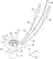
图1是根据本公开引流装置的一些实施例的立体结构示意图;1 is a schematic three-dimensional structural diagram of some embodiments of a drainage device according to the present disclosure;
图2和图3分别是根据本公开引流装置的一些实施例在不同视角下的结构示意图;FIG. 2 and FIG. 3 are respectively schematic structural diagrams of some embodiments of the drainage device according to the present disclosure from different viewing angles;
图4是根据本公开引流装置的一些实施例的内部结构透视示意图;4 is a schematic perspective view of the internal structure of some embodiments of a drainage device according to the present disclosure;
图5是根据本公开直肠引流装置的一些实施例中第一充流管、第二充流管和第一冲洗注药管的结构示意图。5 is a schematic structural diagram of a first filling tube, a second filling tube, and a first irrigation and drug injection tube in some embodiments of a rectal drainage device according to the present disclosure.
应当明白,附图中所示出的各个部分的尺寸并不是按照实际的比例关系绘制的。此外,相同或类似的参考标号表示相同或类似的构件。It should be understood that the dimensions of the various parts shown in the drawings are not to actual scale. Furthermore, the same or similar reference numerals denote the same or similar components.
具体实施方式Detailed ways
现在将参照附图来详细描述本公开的各种示例性实施例。对示例性实施例的描述仅仅是说明性的,决不作为对本公开及其应用或使用的任何限制。本公开可以以许多不同的形式实现,不限于这里所述的实施例。提供这些实施例是为了使本公开透彻且完整,并且向本领域技术人员充分表达本公开的范围。应注意到:除非另外具体说明,否则在这些实施例中阐述的部件和步骤的相对布置、材料的组分、数字表达式和数值应被解释为仅仅是示例性的,而不是作为限制。Various exemplary embodiments of the present disclosure will now be described in detail with reference to the accompanying drawings. The description of the exemplary embodiments is merely illustrative and in no way limits the disclosure, its application or uses in any way. The present disclosure may be implemented in many different forms and is not limited to the embodiments described herein. These embodiments are provided so that this disclosure will be thorough and complete, and will fully convey the scope of the disclosure to those skilled in the art. It should be noted that unless specifically stated otherwise, the relative arrangements of parts and steps, compositions of materials, numerical expressions and numerical values set forth in these embodiments are to be interpreted as illustrative only and not as limiting.
本公开中使用的“第一”、“第二”以及类似的词语并不表示任何顺序、数量或者重要性,而只是用来区分不同的部分。“包括”或者“包含”等类似的词语意指在该词前的要素涵盖在该词后列举的要素,并不排除也涵盖其他要素的可能。“上”、“下”、“左”、“右”等仅用于表示相对位置关系,当被描述对象的绝对位置改变后,则该相对位置关系也可能相应地改变。As used in this disclosure, "first," "second," and similar words do not denote any order, quantity, or importance, but are merely used to distinguish the different parts. "Comprising" or "comprising" and similar words mean that the element preceding the word covers the elements listed after the word, and does not exclude the possibility that other elements are also covered. "Up", "Down", "Left", "Right", etc. are only used to represent the relative positional relationship, and when the absolute position of the described object changes, the relative positional relationship may also change accordingly.
在本公开中,当描述到特定器件位于第一器件和第二器件之间时,在该特定器件与第一器件或第二器件之间可以存在居间器件,也可以不存在居间器件。当描述到特定器件连接其它器件时,该特定器件可以与所述其它器件直接连接而不具有居间器件,也可以不与所述其它器件直接连接而具有居间器件。In the present disclosure, when a specific device is described as being located between the first device and the second device, there may or may not be an intervening device between the specific device and the first device or the second device. When it is described that a specific device is connected to other devices, the specific device may be directly connected to the other device without intervening devices, or may not be directly connected to the other device but have intervening devices.
本公开使用的所有术语(包括技术术语或者科学术语)与本公开所属领域的普通技术人员理解的含义相同,除非另外特别定义。还应当理解,在诸如通用字典中定义的术语应当被解释为具有与它们在相关技术的上下文中的含义相一致的含义,而不应用理想化或极度形式化的意义来解释,除非这里明确地这样定义。All terms (including technical or scientific terms) used in this disclosure have the same meaning as understood by one of ordinary skill in the art to which this disclosure belongs, unless otherwise specifically defined. It should also be understood that terms defined in, for example, general-purpose dictionaries should be construed to have meanings consistent with their meanings in the context of the related art, and not to be construed in an idealized or highly formalized sense, unless explicitly stated herein. Defined like this.
对于相关领域普通技术人员已知的技术、方法和设备可能不作详细讨论,但在适当情况下,所述技术、方法和设备应当被视为说明书的一部分。Techniques, methods, and apparatus known to those of ordinary skill in the relevant art may not be discussed in detail, but where appropriate, such techniques, methods, and apparatus should be considered part of the specification.
在相关技术中,主要采用以下几种直肠减压引流方法:In the related art, the following rectal decompression and drainage methods are mainly used:
1、在结直肠手术后,医生手工进行反复多次的扩肛,以达到降低患者直肠压力、无张力排便的目的。经研究发现,这种方式患者接受度差,增加医生工作量,而且操作部位距离手术部位较近而导致操作受限,降低直肠腔内压力的效果也比较有限。1. After colorectal surgery, the doctor manually expands the anus several times to achieve the purpose of reducing the patient's rectal pressure and defecation without tension. Studies have found that this method is poorly accepted by patients, increases the workload of doctors, and the operation site is close to the operation site, resulting in limited operation, and the effect of reducing the pressure in the rectal cavity is also limited.
2、在直肠腔内固定气囊。这种方式需要使用带气囊的导尿管、气管插管等装置。经研究发现,气囊对直肠粘膜造成持续的压迫,影响直肠壁的血运,并可引起直肠粘膜损伤。另一方面,这种带气囊的装置中的减压引流管具有位于肛门外的外露部分,使得患者的活动及体位受到限制,而且减压引流管的外露部分由于无法确切固定,位置可能发生变动,影响到直肠腔内气囊的位置,从而不可避免地对直肠壁牵拉移位,影响手术部位的愈合。2. Fix the balloon in the rectal cavity. This approach requires the use of balloon catheters, endotracheal tubes, and other devices. Studies have found that the air sac causes continuous pressure on the rectal mucosa, affects the blood supply of the rectal wall, and can cause rectal mucosal damage. On the other hand, the decompression and drainage tube in such a device with a balloon has an exposed part outside the anus, which restricts the movement and posture of the patient, and the position of the exposed part of the decompression and drainage tube may change because it cannot be fixed exactly. , affecting the position of the balloon in the rectal cavity, thereby inevitably pulling and shifting the rectal wall and affecting the healing of the surgical site.
3、肛门外缝合式固定。经研究发现,这种方式固定不确切,容易造成引流管折弯、脱出,外露的减压引流管的位置变动可影响到直肠腔内减压引流管的位置,对直肠壁造成牵拉、移位。并且,位于直肠腔内的管性结构可带来明显的疼痛,并可能造成缝合固定部位的感染。3. External suture fixation of the anus. Studies have found that this method is not accurate, and it is easy to cause the drainage tube to bend and come out. The position change of the exposed decompression and drainage tube can affect the position of the decompression and drainage tube in the rectal cavity, causing traction and displacement of the rectal wall. bit. Also, the tubular structures located in the rectal lumen can cause significant pain and may cause infection of the suture fixation site.
4、肛门外加固定物固定。经研究发现,这种方式不符合人体解剖关系,并且需要附带其他固定物,如固定绳索、腰间圈套等,患者舒适度差。另外,外固定物相互连接的关系复杂,固定不确切,肛门外的外露部件体积大,对患者的体位造成限制,并且外露部件的位置会间接影响直肠内部件的位置,而对直肠壁或吻合口造成牵拉,从而影响吻合口的愈合。4. The anus is fixed with fixed objects. After research, it was found that this method does not conform to the relationship of human anatomy, and needs to be attached with other fixed objects, such as fixed ropes, lumbar snare, etc., and the patient's comfort is poor. In addition, the relationship between the external fixators is complex, the fixation is not exact, the exposed parts outside the anus are bulky, which restricts the patient's position, and the position of the exposed parts will indirectly affect the position of the internal parts of the rectum, and the rectal wall or anastomosis will be affected. The mouth causes traction, which affects the healing of the anastomosis.
有鉴于此,本公开实施例提供一种引流装置,能够减轻气囊组件对人体腔道的粘膜的压迫。In view of this, the embodiments of the present disclosure provide a drainage device, which can reduce the compression of the airbag assembly on the mucous membrane of the human body cavity.
如图1所示,为根据本公开引流装置的一些实施例的立体结构示意图。参考图1,并结合图2-图5所示的结构图,在一些实施例中,引流装置包括:引流管体1和气囊组件2。。气囊组件2设置在所述引流管体1上,且包括多个第一气囊21和多个第二气囊22。As shown in FIG. 1 , it is a schematic three-dimensional structure diagram of some embodiments of the drainage device according to the present disclosure. Referring to FIG. 1 , and in conjunction with the structural diagrams shown in FIGS. 2 to 5 , in some embodiments, the drainage device includes: a
在一些实施例中,气囊组件2可采用柔性防水不透气的材料,例如聚氯乙烯(PVC)等。气囊组件2包括的多个第一气囊21和所述多个第二气囊22沿所述引流管体1的周向排布。在图1中,多个第一气囊21和多个第二气囊22相对于所述引流管体1沿所述引流管体1的径向外侧呈放射状,类似于花瓣的形状。多个第一气囊21和多个第二气囊22能够随内部的工作流体的体积的增加而沿径向扩张,并随内部的工作流体的体积的减小而沿径向收缩。气囊组件2可充入或释放液态或气态的工作流体,例如空气、水、油等。以空气为例,通过向气囊组件2的部分或全部气囊充入空气来改变气囊组件2内的充气量和气压,可以使得部分或全部气囊沿径向扩张或收缩。呈收缩状态的气囊组件2容易随引流管体1一起进入人体腔道(例如经过肛门进入直肠),而呈扩张状态的气囊组件2则能够对人体腔道的腔壁(例如直肠肠腔的腔壁)进行支撑。在一些应用场景中(例如术后或术中的直肠减压引流),可使得第一气囊和第二气囊分别呈现不同的扩张程度,来对直肠肠腔的腔壁粘膜形成非连续的局部压迫。而在另一些应用场景中(例如直肠远端出血的局部压迫治疗或结直肠损伤的保守治疗),则可使气囊组件2中的所有气囊呈相同程度的扩张,以抑制直肠远端出血。In some embodiments, the
为了便于对第一气囊和第二气囊的扩张程度的独立控制,在一些实施例中,可使多个第一气囊21的充入和释放工作流体的过程与所述多个第二气囊22的充入和释放工作流体的过程相互独立。例如,使得多个第一气囊21与多个第二气囊22相互之间不连通。In order to facilitate the independent control of the degree of expansion of the first airbag and the second airbag, in some embodiments, the process of filling and releasing the working fluid of the plurality of
与一些沿引流管体的轴向分别布置的多个环形气囊,且交替充气的相关技术相比,本实施例中沿引流管体的周向排布充放工作流体过程相互独立的多个第一气囊和多个第二气囊,一方面可以通过对第一气囊和第二气囊交替进行工作流体的充入和释放,在对人体腔道进行支撑时能够避免形成对腔壁粘膜的持续性局部压迫;另一方面通过周向排布多个气囊,无需采用较长的引流管体,减少或避免引流管体位于人体腔道内较长的部分对腔壁的损伤的风险。Compared with some related technologies in which a plurality of annular airbags are arranged along the axial direction of the drainage tube body and are inflated alternately, in this embodiment, a plurality of annular airbags are arranged along the circumferential direction of the drainage tube body and the process of charging and discharging the working fluid is independent of each other. An air bag and a plurality of second air bags, on the one hand, by alternately filling and releasing the working fluid from the first air bag and the second air bag, when supporting the human body cavity, it can avoid the formation of a persistent part of the mucous membrane of the cavity wall. Compression; on the other hand, by arranging multiple airbags in the circumferential direction, there is no need to use a long drainage tube body, and the risk of damage to the cavity wall caused by the longer part of the drainage tube body located in the human cavity is reduced or avoided.
在图1中,多个第一气囊21和多个第二气囊22均位于引流管体1在轴向上的同一位置。另外,第一气囊21的数量可以与第二气囊22的数量相同或不同,例如均为6个。In FIG. 1 , the plurality of
为了确保气囊组件2对人体腔道的局部支撑的均匀性,可使得所述第一气囊21(即图1中白色的气囊)与所述第二气囊22(即图1中的灰色的气囊)沿引流管体1的周向交替设置,即多个气囊中沿一个圆周方向(顺时针或逆时针)依次为第一气囊21、第二气囊22、第一气囊21、第二气囊22……。In order to ensure the uniformity of the partial support of the
通过将多个第一气囊21的充入和释放工作流体的过程与所述多个第二气囊22的充入和释放工作流体的过程设置成相互独立,能够有效地避免第一气囊21和第二气囊22内部的工作流体的流量或压力控制之间发生相互干扰。By setting the process of filling and releasing the working fluid of the plurality of
参考图1和图3,在一些实施例中,气囊组件2位于所述引流管体1沿轴向第一侧的端部,相邻的所述第一气囊21与所述第二气囊22在扩张状态下相互紧贴,并在所述第一气囊21与所述第二气囊22之间形成位于第一侧的沟槽27。在图1中,沿周向的每组相邻的第一气囊21和第二气囊22之间均能形成内凹的沟槽27。该沟槽27能够有效地引导人体腔道的内容物向位于中心的引流管体的管口流动,从而提高引流效果。Referring to FIGS. 1 and 3 , in some embodiments, the
参考图1-图5,在一些实施例中,引流装置还包括外固定座3。外固定座3设置在所述引流管体1上,能够在所述引流管体1插入人体腔道的状态下,与所述气囊组件2分别在所述人体腔道的腔道口外侧和内侧沿所述引流管体1的轴向对所述引流管体1进行固定限位。Referring to FIGS. 1-5 , in some embodiments, the drainage device further includes an outer fixing
举例来说,当引流装置应用于直肠引流时,引流管体1经肛门插入直肠下端,气囊组件2和外固定座3能够分别在所述肛门内侧和外侧沿所述引流管体1的轴向对所述引流管体1进行固定限位,从而实现直肠腔内和肛门外侧的双重固定,使得固定更加确切,更加符合人体解剖结构及生理功能,使患者更加舒适,且降低临床医务人员的工作量。另外,也可省去其他辅助固定装置,从而使引流装置的稳定性和固定位置不容易受到患者肢体活动的影响,也不容易影响患者的肢体活动和体位。For example, when the drainage device is applied to rectal drainage, the
在一些实施例中,引流管体1可采用聚氨酯材料制成。这种材料的人体耐受性好,能够承受一些人体腔道的腔道口的挤压而不发生明显形变,从而确保引流管体1的管腔保持通畅。例如应用在直肠引流时,引流管体1能够在肛门内外括约肌的压力下不发生明显形变,有效地降低直肠腔内压力,为结直肠手术创造低压力环境,促进吻合口的愈合,降低吻合口瘘的发生机率。In some embodiments, the
引流管体1在使用时可留置在人体腔道的远端(即邻近腔道口的一端),例如直肠邻近肛门一侧的下端。通过气囊组件在人体腔道内的固定,可省去位于人体腔道的近端(即远离腔道口的一端)的管性结构设置。这样在一些实施例中,在引流管体1位于人体腔道的近端不设置管性结构,从而使引流管体更短,引流阻力更小,且不会对人体腔道内的手术部位造成牵拉移位的伤害。The
参考图2,在一些实施例中,所述气囊组件2位于所述引流管体1沿轴向第一侧的端部,所述气囊组件2至少在扩张状态下与所述引流管体1的端部平齐或超出所述引流管体1的端部。换句话说,沿图2中的z轴方向,气囊组件2在扩张状态下的最高位置不低于引流管体1的上端。这样可以有效地避免气囊组件2之上的管性结构对腔壁粘膜造成损伤。Referring to FIG. 2 , in some embodiments, the
在图2中,可将外固定座3设置在所述引流管体1沿轴向第二侧的端部,即图2中沿z轴方向的引流管体1的下端。并且,使得所述引流管体1的第二侧端部沿轴向未超出所述外固定座3远离所述气囊组件2的一侧的最远端。换句话说,使得外固定座3的最低位置不低于引流管体1的下端。这样可使得本实施例的引流装置在腔道口外无管性结构,从而使得患者能够自由活动而不会影响引流装置的稳定性和固定部位。在另一些实施例中,引流管体1的下端相对于外固定座3的最下端可略向下突出。In FIG. 2 , the outer fixing
以直肠手术为例,由于不同患者的肛管长度不同,医疗人员可通过指诊或通过仪器确定肛管长度,并选择适合的引流管体长度的相应规格的引流装置。在一些实施例中,引流管体1的长度可选为50~60mm,以满足直肠引流的需求。Taking rectal surgery as an example, since different patients have different lengths of anal canals, medical personnel can determine the length of the anal canal through digital examination or through instruments, and select a drainage device of the corresponding specification suitable for the length of the drainage tube body. In some embodiments, the length of the
在一些实施例中,在所述引流管体1的轴向上,所述外固定座3与所述引流管体1之间的固定位置可调节。例如,在引流管体1上设置多个档位,外固定座3可沿引流管体1的轴向移动位置,并在对应的档位上与引流管体1通过卡接、螺钉连接等方式固定连接。相应地,可在引流管体1上设置可识别的刻度。In some embodiments, in the axial direction of the
在一些实施例中,引流管体1的内径为10~20mm,可选为15mm,不仅可通过较宽的管腔内径来使引流更加通畅,而且能够降低患者使用引流装置的不适感。为了在管壁内容纳例如充流管或冲洗注药管,在一些实施例中,可将引流管体1的管壁厚度设置为1~2mm,可选为1.5mm。In some embodiments, the inner diameter of the
参考图3,在一些实施例中,所述气囊组件2在扩张状态下的最大直径D为28~38mm。参考图2,在一些实施例中,所述气囊组件2在沿所述引流管体1的轴向上的高度H为6~12mm,可选为10mm。另外,在一些实施例中,气囊组件2至少在所述扩张状态下与所述引流管体1的端部平齐或高于所述引流管体1的端部。例如在图4中扩张状态的气囊组件2的最高位置与引流管体1的顶端平齐,从而使引流管体1不具有位于气囊组件以上的管性结构。Referring to FIG. 3 , in some embodiments, the maximum diameter D of the
参考图4和图5,在一些实施例中,引流装置还包括:第一充流管23和第二充流管24。第一充流管23和第二充流管24位于所述引流管体1的管壁内。所述第一充流管23包括第一环形管段23a和第一直管段23b,所述第一环形管段23a分别与所述多个第一气囊21连通,所述第一直管段23b与所述第一环形管段23a连通,且沿所述引流管体1的轴向延伸。第二充流管24包括第二环形管段24a和第二直管段24b,所述第二环形管段24a分别与所述多个第二气囊22连通,所述第二直管段24b与所述第二环形管段24a连通,且沿所述引流管体1的轴向延伸。4 and 5, in some embodiments, the drainage device further includes: a
在图5,第一环形管段23a沿周向设有多个开口,并可通过该多个开口分别与周向上间隔排列的多个第一气囊21连通。第二环形管段24a沿周向设有多个开口,并可通过该多个开口分别与周向上间隔排列的多个第二气囊22连通。第一环形管段23a和第二环形管段24a可分别位于引流管体1轴向的不同位置。In FIG. 5 , the first
参考图4,在一些实施例中,引流装置还包括:第三充流管25和第四充流管26。第三充流管25具有位于所述外固定座3内、且与所述第一充流管23连通的第一部分25a和与所述第一部分25a连通、并从所述外固定座3向外引出的第二部分25b。第四充流管26具有位于所述外固定座3内、且与所述第二充流管24连通的第三部分26a和与所述第三部分26a连通、并从所述外固定座3向外引出的第四部分26b。Referring to FIG. 4 , in some embodiments, the drainage device further includes: a
在图4中,第一充流管23的第一直管段23b与第三充流管25的第一部分25a连接。在一些实施例中,第一充流管23与第三充流管25可一体制成。在图4中,第二充流管24的第二直管段24b与第四充流管26的第三部分26a连接。在一些实施例中,第二充流管24与第四充流管26可一体制成。In FIG. 4 , the first
第三充流管25和第四充流管26分别从外固定座3向外引出的第二部分25b和第四部分26b的长度可根据需要进行设置,例如设置成引出到患者腹部的长度,以方便医务人员操作。工作流体能够经过第三充流管25和第一充流管23进入第一气囊21,并经过第四充流管25和第二充流管24进入第二气囊22。工作流体的驱动可在第三充流管25和第四充流管26分别从外固定座3向外引出的第二部分25b和第四部分26b完成。The lengths of the
参考图1-图4,在一些实施例中,引流装置还包括:第一测压气囊27和第二测压气囊28。第一测压气囊27与所述第三充流管25的第二部分25b连通,能够经由所述第三充流管25和所述第一充流管23向所述多个第一气囊21注入工作流体。第二测压气囊28与所述第四充流管26的第四部分26b连通,能够经由所述第四充流管26和所述第二充流管24向所述多个第二气囊22注入工作流体。这里的第一测压气囊27和第二测压气囊28作为工作流体的驱动装置能够实现工作流体的充入操作。操作人员可以手动对第一测压气囊27或第二测压气囊28进行挤压来实现充入流体的操作。Referring to FIGS. 1-4 , in some embodiments, the drainage device further includes: a first pressure-measuring
在第一测压气囊和第二测压气囊上可分别设置密封头,以维持第一气囊和第二气囊内的工作流体压力,当开启第一测压气囊和第二测压气囊中的任一个的密封头后,可实现对应的第一气囊或第二气囊内的工作流体的释放。另外,第一测压气囊和第二测压气囊能够对工作流体的压力进行测量,从而更精准地控制第一气囊和第二气囊的工作流体的充放,更好地估计气囊组件的扩张程度。A sealing head can be provided on the first pressure measuring airbag and the second pressure measuring airbag respectively to maintain the working fluid pressure in the first pressure measuring airbag and the second pressure measuring airbag. After one sealing head, the release of the working fluid in the corresponding first airbag or the second airbag can be realized. In addition, the first pressure-measuring airbag and the second pressure-measuring airbag can measure the pressure of the working fluid, so as to control the charging and discharging of the working fluid of the first airbag and the second airbag more accurately, and better estimate the expansion degree of the airbag assembly .
为了简化人工操作,提高引流装置的自动化和使用便利性,在一些实施例中,引流装置还可包括:流体引导设备。该流体引导设备分别与所述第三充流管25的第二部分25b和所述第四充流管26的第四部分26b连通,被配置为根据设定程序引导工作流体按照预设周期交替地流入所述多个第一气囊21和所述多个第二气囊22。In order to simplify manual operation and improve the automation and convenience of use of the drainage device, in some embodiments, the drainage device may further include: a fluid guiding device. The fluid guiding device communicates with the
在一些实施例中,流体引导设备可包括气泵、气阀和微处理器或控制器,通过微处理器或控制器对气阀和气泵进行控制,以实现对多个第一气囊21和多个第二气囊22按照预设周期的交替充放操作。利用流体引导设备来实现自动化地向第一气囊和/或第二气囊充入工作流体或释放第一气囊和/或第二气囊内的工作流体,并可对工作流体的工作参数,例如压力、流量等进行检测。In some embodiments, the fluid guiding device may include an air pump, an air valve, and a microprocessor or controller, and the air valve and the air pump are controlled by the microprocessor or controller, so as to realize the control of the plurality of
参考图1和图2,在一些实施例中,引流装置还包括引流容器4。引流容器4位于所述外固定座3远离所述气囊组件2的一侧,且与所述引流管体1远离所述气囊组件2的一端形成可装拆的连接。引流容器4通过与引流管体1连接,可方便地收集直肠内部流体,例如直肠肠腔内的内容物或冲洗肠壁后的药液。Referring to FIGS. 1 and 2 , in some embodiments, the drainage device further includes a
在一些实施例中,引流容器4包括采用柔性材料(例如塑胶或硅胶等)制作de柔性引流袋,以免影响患者的体位(例如坐位或直立体位等)。In some embodiments, the
参考图2,在一些实施例中,引流容器4具有与所述引流管体1远离所述气囊组件2的一端进行插接的接驳口。该接驳口可采用环形插接式结构,其外径可小于等于引流管体1的内径,以便插入引流管体1的下端。接驳口的长度可以为10~30mm,例如20mm,以便与引流管体1形成稳定可靠的连接。所述引流容器4的底部的截面积大于所述接驳口的截面积。在图2中可以看到引流容器4的底部宽度W5大于接驳口宽度W4,引流容器的这种渐宽结构能够有效地降低减压引流的阻力。Referring to FIG. 2 , in some embodiments, the
在一些实施例中,外固定座3的材料是透明的,以方便医护人员对人体腔道内部进行观察。例如外固定座3可采用但不限于透明硅胶。透明硅胶材质较柔软,可增加患者的接受程度和依从性,方便患者自由活动,从而缩短恢复时间,减少因长时间卧床产生的并发症。In some embodiments, the material of the
参考图1-图4,在一些实施例中,外固定座3包括:管体连接部31、第一固定部32和第二固定部33。管体连接部31与所述引流管体1连接。参考图1-图4,z轴与引流管体的轴线平行,x轴和y轴均与z轴平行,x轴与y轴平行。在一些实施例中,y轴的延伸方向与人体的矢状面垂直,x轴的延伸方向与人体的冠状面垂直,z轴的延伸方向与人体的横截面垂直。这里将x轴的延伸方向定义为外固定座3的纵向,将y轴的延伸方向定义为外固定座3的横向。第一固定部32和第二固定部33沿纵向分别连接在所述管体连接部31的两侧。Referring to FIGS. 1-4 , in some embodiments, the
在将引流装置应用在直肠引流时,所述第一固定部32被配置为在所述引流管体1插入直肠的状态下,对人体的会阴部及所述会阴部到肛门的皮肤进行抵靠。所述第二固定部被配置为在所述引流管体1插入直肠的状态下,对人体的尾骨尖及所述尾骨尖到肛门的皮肤进行抵靠。When the drainage device is applied to rectal drainage, the first fixing
通过第一固定部和第二固定部分别在人体前后两侧的固定,使得引流管体的固定更加牢靠。参考图2,为了更加符合人体解剖及生理结构,可使第一固定部32和第二固定部33邻近所述气囊组件2一侧的表面相对于所述气囊组件2呈内凹弧面。在图1和图2中,第一固定部32和第二固定部33相对于所述引流管体1与所述管体连接部31的连接部位,朝向所述气囊组件2一侧弯曲。这样可使得外固定座3呈现锚状结构,从而允许患者自由活动而不影响引流装置的稳定性和固定位置。The first fixing part and the second fixing part are respectively fixed on the front and rear sides of the human body, so that the fixing of the drainage tube body is more reliable. Referring to FIG. 2 , in order to better conform to human anatomy and physiological structure, the surfaces of the first fixing
参考图3,在一些实施例中,第一固定部32的横向宽度W1大于所述第二固定部33的横向宽度W2。参考前述这种结构更加符合人体解剖及生理结构,从而更好地固定且提高患者的舒适度。例如在图3中,W1为30mm,W2为10mm。外固定座3在第二方向x上的长度可为90mm,外固定座3的厚度为5mm。Referring to FIG. 3 , in some embodiments, the lateral width W1 of the first fixing
在图3中,所述外固定座3的横向宽度从所述第一固定部32到所述第二固定部33的方向逐渐减小,且所述第一固定部32远离所述管体连接部31一侧的端部和所述第二固定部33远离所述管体连接部31一侧的端部均呈圆弧形。这种结构不仅更加符合人体解剖及生理结构,而且患者使用更加舒适。在一些应用场景下,需要向人体腔道内通入治疗用的药液或者清洗用的清洗液,例如在术后向直肠内通入药液或对直肠内部进行冲洗。相应地,参考图1-图5,在一些实施例中,引流装置还包括第一冲洗注药管51和第二冲洗注药管52。第一冲洗注药管51的至少部分位于所述引流管体1的管壁内。第一冲洗注药管51包括第三环形管段51a和第三直管段51b,所述第三环形管段51a位于所述引流管体1远离所述外固定座3的一侧,所述第三直管段51b与所述第三环形管段51a连通,且沿所述引流管体1的轴向延伸。In FIG. 3 , the lateral width of the
所述第三环形管段51a沿周向设有多个开孔54,所述多个开孔54被配置为向外喷射冲洗液或药液。在一些实施例中,各个开孔54上还可设置喷头。通过第三环形管段51a上设置的多个开孔54进行冲洗注药操作,可以使人体腔道的冲洗或注药更加充分。开孔的数量可根据需要进行设置,例如设置4~8个开孔,可选为6个开孔。多个开孔54可沿周向等间隔布置。在另一些实施例中,多个开孔54可沿周向非等间隔布置。The third
参考图2,在一些实施例中,第三环形管段51a位于引流管体1的端部的轴向外侧,例如图2中的引流管体1的顶端之上。而参考图4,在另一些实施例中,第三环形管段51a位于引流管体1的管壁内,且位于邻近引流管体1的顶端的位置,而引流管体1的顶端也设置多个开口,且分别与第三环形管段51a的多个开孔54对齐,这样进入第三环形管段51a的工作流体能够经过开孔54和引流管体1顶端的开口向上喷射。Referring to FIG. 2 , in some embodiments, the third
第二冲洗注药管52具有位于所述外固定座3内、且与所述第三直管段51b连通的第五部分52a和与所述第五部分52a连通、并从所述外固定座3向外引出的第六部分52b。在一些实施例中,第二冲洗注药管52与第一冲洗注药管51可一体制成。The second flushing and
第二冲洗注药管52的从所述外固定座3向外引出的第六部分52b可与提供冲洗液或药液的设备连接,以便向人体腔道内注入冲洗液或药液。The
参考图1和图4,在一些实施例中,第二冲洗注药管52、所述第二充流管24和所述第四充流管26均在所述第一固定部32远离所述管体连接部31一侧的端部向外引出。,以方便医护人员进行操作。Referring to FIG. 1 and FIG. 4 , in some embodiments, the
参考图4和图5,在一些实施例中,第一冲洗注药管51的至少部分与第一充流管23和第二充流管24在引流管体1的管壁内设置。在图5中,第一冲洗注药管51的第三直管段51b与第一充流管23的第一直管段23b和第二充流管24的第二直管段24b并排且紧贴设置,以简化制造工艺。第三环形管段51a与第一环形管段23a和第二环形管段24a平行,且沿引流管体1的轴向间隔布置。在另一些实施例中,第三直管段51b与第一直管段23b和第二直管段24b位于不同的角度位置而不紧贴。Referring to FIGS. 4 and 5 , in some embodiments, at least part of the first flushing and
参考本公开引流装置的前述各实施例,下面对将引流装置应用到直肠术后的实例进行说明。With reference to the foregoing embodiments of the drainage device of the present disclosure, an example of applying the drainage device to rectal surgery is described below.
临床医生可先直肠指诊来评估肛管长度,借此选择合适规格的引流装置。通过测压气囊对引流装置的气囊组件进行充气以检测气囊组件的充气量及膨胀程度,再将气囊组件内气体抽空。Clinicians can first assess the length of the anal canal with digital rectal examination to select the appropriate size drainage device. The airbag assembly of the drainage device is inflated by the pressure measuring airbag to detect the inflation amount and degree of inflation of the airbag assembly, and then the air in the airbag assembly is evacuated.
使患者处于截石位,将外固定座的第二固定部对着尾骨尖的位置,第一固定部对着会阴部的位置,并将引流管体经肛门置入直肠下端。通过引流管体的下端开口观察直肠内情况及留置位置,再对第一气囊和第二气囊中的一种充气,待一段时间(例如12小时)后给第一气囊和第二气囊中的另一种充气,并对原先充气的气囊进行放气。这样交替反复,可使得直肠肠壁的局部受压情况得以改善。Put the patient in the lithotomy position, place the second fixation part of the external fixator against the tip of the coccyx and the first fixation part against the perineum, and place the drainage tube into the lower end of the rectum through the anus. Observe the situation in the rectum and the indwelling position through the opening of the lower end of the drainage tube body, and then inflate one of the first airbag and the second airbag. An inflation that deflates a previously inflated bladder. Repeating this alternately can improve the local compression of the rectal wall.
在引流装置固定确切后,将柔性引流袋插接于引流管体下端的开口,用于接收直肠内的内容物。当需要更换柔性引流袋时,可将接驳口从引流管体的下端开口直接拔出,并更换新的柔性引流袋。当需要去除引流装置时,将气囊组件内的气体全部抽净,再从肛门外缘缓慢取出。After the drainage device is fixed correctly, the flexible drainage bag is inserted into the opening at the lower end of the drainage tube body to receive the contents in the rectum. When the flexible drainage bag needs to be replaced, the connection port can be directly pulled out from the lower end opening of the drainage tube body, and a new flexible drainage bag can be replaced. When it is necessary to remove the drainage device, all the gas in the airbag assembly is pumped out, and then slowly taken out from the outer edge of the anus.
当直肠远端出血时,可将第一气囊和第二气囊同时充气,以便实现加压止血。在进行结直肠损伤的吻合口瘘保守治疗时,可经冲洗注药管滴注灌肠液及治疗药物,并通过柔性引流袋内的引流物的性状评估治疗效果。When bleeding from the distal rectum, the first balloon and the second balloon can be inflated at the same time to achieve pressure hemostasis. In the conservative treatment of anastomotic leakage of colorectal injury, enema solution and therapeutic drugs can be instilled through a flushing injection tube, and the treatment effect can be evaluated by the properties of the drainage material in the flexible drainage bag.
至此,已经详细描述了本公开的各实施例。为了避免遮蔽本公开的构思,没有描述本领域所公知的一些细节。本领域技术人员根据上面的描述,完全可以明白如何实施这里公开的技术方案。So far, the various embodiments of the present disclosure have been described in detail. Some details that are well known in the art are not described in order to avoid obscuring the concept of the present disclosure. Those skilled in the art can fully understand how to implement the technical solutions disclosed herein based on the above description.
虽然已经通过示例对本公开的一些特定实施例进行了详细说明,但是本领域的技术人员应该理解,以上示例仅是为了进行说明,而不是为了限制本公开的范围。本领域的技术人员应该理解,可在不脱离本公开的范围和精神的情况下,对以上实施例进行修改或者对部分技术特征进行等同替换。本公开的范围由所附权利要求来限定。While some specific embodiments of the present disclosure have been described in detail by way of examples, those skilled in the art will appreciate that the above examples are provided for illustration only, and are not intended to limit the scope of the present disclosure. Those skilled in the art should understand that, without departing from the scope and spirit of the present disclosure, the above embodiments can be modified or some technical features can be equivalently replaced. The scope of the present disclosure is defined by the appended claims.
Claims (22)
Translated fromChinesePriority Applications (1)
| Application Number | Priority Date | Filing Date | Title |
|---|---|---|---|
| CN202010567413.3ACN111588925B (en) | 2020-06-19 | 2020-06-19 | Drainage devices |
Applications Claiming Priority (1)
| Application Number | Priority Date | Filing Date | Title |
|---|---|---|---|
| CN202010567413.3ACN111588925B (en) | 2020-06-19 | 2020-06-19 | Drainage devices |
Publications (2)
| Publication Number | Publication Date |
|---|---|
| CN111588925Atrue CN111588925A (en) | 2020-08-28 |
| CN111588925B CN111588925B (en) | 2024-12-10 |
Family
ID=72182669
Family Applications (1)
| Application Number | Title | Priority Date | Filing Date |
|---|---|---|---|
| CN202010567413.3AActiveCN111588925B (en) | 2020-06-19 | 2020-06-19 | Drainage devices |
Country Status (1)
| Country | Link |
|---|---|
| CN (1) | CN111588925B (en) |
Cited By (2)
| Publication number | Priority date | Publication date | Assignee | Title |
|---|---|---|---|---|
| CN112023139A (en)* | 2020-09-15 | 2020-12-04 | 上海翊箬医药科技有限公司 | Excrement management system |
| CN113101500A (en)* | 2021-04-30 | 2021-07-13 | 中国人民解放军陆军军医大学第一附属医院 | Controllable rectal cancer postoperative pressure release pipe |
Citations (7)
| Publication number | Priority date | Publication date | Assignee | Title |
|---|---|---|---|---|
| US5865801A (en)* | 1995-07-18 | 1999-02-02 | Houser; Russell A. | Multiple compartmented balloon catheter with external pressure sensing |
| CN101239204A (en)* | 2008-02-27 | 2008-08-13 | 刘忠臣 | Three-cavity air bag type rectum anal tube drainage flusher |
| EP2857051A2 (en)* | 2013-10-03 | 2015-04-08 | A.M.I. Agency for Medical Innovations GmbH | Device for the treatment of internal injury to the gastro-intestinal tract |
| CN105749364A (en)* | 2016-03-14 | 2016-07-13 | 南京医科大学第附属医院 | Collection device for fecal incontinence |
| CN206214485U (en)* | 2016-08-26 | 2017-06-06 | 刘莉莉 | Fecal collecting device |
| CN109717993A (en)* | 2018-12-13 | 2019-05-07 | 云南省第一人民医院 | A kind of Breast Surgery postoperative rehabilitation auxiliary device |
| CN212593263U (en)* | 2020-06-19 | 2021-02-26 | 陕西稻田诊断试剂有限公司 | Drainage device |
- 2020
- 2020-06-19CNCN202010567413.3Apatent/CN111588925B/enactiveActive
Patent Citations (7)
| Publication number | Priority date | Publication date | Assignee | Title |
|---|---|---|---|---|
| US5865801A (en)* | 1995-07-18 | 1999-02-02 | Houser; Russell A. | Multiple compartmented balloon catheter with external pressure sensing |
| CN101239204A (en)* | 2008-02-27 | 2008-08-13 | 刘忠臣 | Three-cavity air bag type rectum anal tube drainage flusher |
| EP2857051A2 (en)* | 2013-10-03 | 2015-04-08 | A.M.I. Agency for Medical Innovations GmbH | Device for the treatment of internal injury to the gastro-intestinal tract |
| CN105749364A (en)* | 2016-03-14 | 2016-07-13 | 南京医科大学第附属医院 | Collection device for fecal incontinence |
| CN206214485U (en)* | 2016-08-26 | 2017-06-06 | 刘莉莉 | Fecal collecting device |
| CN109717993A (en)* | 2018-12-13 | 2019-05-07 | 云南省第一人民医院 | A kind of Breast Surgery postoperative rehabilitation auxiliary device |
| CN212593263U (en)* | 2020-06-19 | 2021-02-26 | 陕西稻田诊断试剂有限公司 | Drainage device |
Cited By (3)
| Publication number | Priority date | Publication date | Assignee | Title |
|---|---|---|---|---|
| CN112023139A (en)* | 2020-09-15 | 2020-12-04 | 上海翊箬医药科技有限公司 | Excrement management system |
| CN112023139B (en)* | 2020-09-15 | 2025-03-18 | 上海翊箬医药科技有限公司 | A stool management system |
| CN113101500A (en)* | 2021-04-30 | 2021-07-13 | 中国人民解放军陆军军医大学第一附属医院 | Controllable rectal cancer postoperative pressure release pipe |
Also Published As
| Publication number | Publication date |
|---|---|
| CN111588925B (en) | 2024-12-10 |
Similar Documents
| Publication | Publication Date | Title |
|---|---|---|
| US11324932B2 (en) | Trans-anal inflow catheter for intermittently triggering a reflex-coordinated defecation | |
| CN102573617B (en) | Systems, devices and methods for assessment of body cavity pressures | |
| US8579850B2 (en) | Irrigation device and method of using the device | |
| US20180311480A1 (en) | Trans-anal inflow catheter for intermittently triggering a reflex-coordinated defecation | |
| CN103405845B (en) | A kind of Ileum fistulization tube | |
| CN111588925A (en) | Drainage device | |
| CN212593263U (en) | Drainage device | |
| CN110680514A (en) | Laparoscopic use of pelvic and abdominal isolation to protect diaphragm | |
| CN204170277U (en) | There is the stomach tube of local hemostasis effect | |
| CN112843375A (en) | Anti-backflow stoma enema device | |
| US20230041626A1 (en) | Method and device for intermittently triggering a reflex-coordinated defecation | |
| CN204411473U (en) | Sterility treatment oviduct-radiography catheter | |
| CN214596529U (en) | Air bag internal fixation foldable external fixation type stomach tube | |
| CN214859854U (en) | An anti-reflux stoma enema device | |
| CN215536973U (en) | Exhaust hemostasis perfusion treatment anal canal | |
| CN213097917U (en) | Anal sphincter function evaluation device | |
| CN215534895U (en) | Balloon device with sensor | |
| CN210355407U (en) | Feeding tube | |
| CN114532968A (en) | Tubular vaginal dilation assembly | |
| CN218739839U (en) | Rectal balloon catheter device | |
| RU2452522C2 (en) | Colon cleansing device | |
| CN211724352U (en) | Balloon dilatation device for hepatobiliary surgery | |
| CN214908982U (en) | Uropoiesis is leak protection urethral catheterization device for surgery nursing | |
| CN215308978U (en) | Novel enema tube | |
| CN221692527U (en) | A fixed ureteral guide sheath |
Legal Events
| Date | Code | Title | Description |
|---|---|---|---|
| PB01 | Publication | ||
| PB01 | Publication | ||
| SE01 | Entry into force of request for substantive examination | ||
| SE01 | Entry into force of request for substantive examination | ||
| CB03 | Change of inventor or designer information | Inventor after:Zhou Ge Inventor after:Liu Hannan Inventor before:Zhou Ge | |
| CB03 | Change of inventor or designer information | ||
| TA01 | Transfer of patent application right | Effective date of registration:20210127 Address after:Room 12504, 12505, 25 / F, unit 1, building 4, blue ocean, Greenland Central Plaza, Jinye Road, high tech Zone, Xi'an, Shaanxi 710000 Applicant after:Shaanxi paddy Diagnostic Reagent Co.,Ltd. Address before:Room 12501, 25 / F, unit 1, building 4, blue ocean, Greenland Central Plaza, high tech Zone, Xi'an, Shaanxi 710000 Applicant before:Paddy field medical and Health Industry Investment Group Co.,Ltd. | |
| TA01 | Transfer of patent application right | ||
| GR01 | Patent grant | ||
| GR01 | Patent grant |