CN111587397B - Image generation device, spectacle lens selection system, image generation method, and program - Google Patents
Image generation device, spectacle lens selection system, image generation method, and programDownload PDFInfo
- Publication number
- CN111587397B CN111587397BCN201880086181.0ACN201880086181ACN111587397BCN 111587397 BCN111587397 BCN 111587397BCN 201880086181 ACN201880086181 ACN 201880086181ACN 111587397 BCN111587397 BCN 111587397B
- Authority
- CN
- China
- Prior art keywords
- subject
- image
- display device
- view
- distance
- Prior art date
- Legal status (The legal status is an assumption and is not a legal conclusion. Google has not performed a legal analysis and makes no representation as to the accuracy of the status listed.)
- Active
Links
Images


Classifications
- A—HUMAN NECESSITIES
- A61—MEDICAL OR VETERINARY SCIENCE; HYGIENE
- A61B—DIAGNOSIS; SURGERY; IDENTIFICATION
- A61B3/00—Apparatus for testing the eyes; Instruments for examining the eyes
- A61B3/0016—Operational features thereof
- A61B3/0025—Operational features thereof characterised by electronic signal processing, e.g. eye models
- A—HUMAN NECESSITIES
- A61—MEDICAL OR VETERINARY SCIENCE; HYGIENE
- A61B—DIAGNOSIS; SURGERY; IDENTIFICATION
- A61B3/00—Apparatus for testing the eyes; Instruments for examining the eyes
- A61B3/0016—Operational features thereof
- A61B3/0041—Operational features thereof characterised by display arrangements
- A—HUMAN NECESSITIES
- A61—MEDICAL OR VETERINARY SCIENCE; HYGIENE
- A61B—DIAGNOSIS; SURGERY; IDENTIFICATION
- A61B3/00—Apparatus for testing the eyes; Instruments for examining the eyes
- A61B3/02—Subjective types, i.e. testing apparatus requiring the active assistance of the patient
- A61B3/028—Subjective types, i.e. testing apparatus requiring the active assistance of the patient for testing visual acuity; for determination of refraction, e.g. phoropters
- A61B3/032—Devices for presenting test symbols or characters, e.g. test chart projectors
- A—HUMAN NECESSITIES
- A61—MEDICAL OR VETERINARY SCIENCE; HYGIENE
- A61B—DIAGNOSIS; SURGERY; IDENTIFICATION
- A61B3/00—Apparatus for testing the eyes; Instruments for examining the eyes
- A61B3/02—Subjective types, i.e. testing apparatus requiring the active assistance of the patient
- A61B3/028—Subjective types, i.e. testing apparatus requiring the active assistance of the patient for testing visual acuity; for determination of refraction, e.g. phoropters
- A61B3/04—Trial frames; Sets of lenses for use therewith
- A—HUMAN NECESSITIES
- A61—MEDICAL OR VETERINARY SCIENCE; HYGIENE
- A61B—DIAGNOSIS; SURGERY; IDENTIFICATION
- A61B3/00—Apparatus for testing the eyes; Instruments for examining the eyes
- A61B3/10—Objective types, i.e. instruments for examining the eyes independent of the patients' perceptions or reactions
- A61B3/113—Objective types, i.e. instruments for examining the eyes independent of the patients' perceptions or reactions for determining or recording eye movement
- G—PHYSICS
- G06—COMPUTING OR CALCULATING; COUNTING
- G06F—ELECTRIC DIGITAL DATA PROCESSING
- G06F3/00—Input arrangements for transferring data to be processed into a form capable of being handled by the computer; Output arrangements for transferring data from processing unit to output unit, e.g. interface arrangements
- G06F3/14—Digital output to display device ; Cooperation and interconnection of the display device with other functional units
- G06F3/147—Digital output to display device ; Cooperation and interconnection of the display device with other functional units using display panels
Landscapes
- Health & Medical Sciences (AREA)
- Life Sciences & Earth Sciences (AREA)
- Engineering & Computer Science (AREA)
- Physics & Mathematics (AREA)
- Medical Informatics (AREA)
- Animal Behavior & Ethology (AREA)
- Veterinary Medicine (AREA)
- Public Health (AREA)
- Biophysics (AREA)
- Ophthalmology & Optometry (AREA)
- Biomedical Technology (AREA)
- Heart & Thoracic Surgery (AREA)
- General Health & Medical Sciences (AREA)
- Molecular Biology (AREA)
- Surgery (AREA)
- Theoretical Computer Science (AREA)
- Human Computer Interaction (AREA)
- General Engineering & Computer Science (AREA)
- General Physics & Mathematics (AREA)
- Signal Processing (AREA)
- Processing Or Creating Images (AREA)
- Eyeglasses (AREA)
- Eye Examination Apparatus (AREA)
- Image Analysis (AREA)
- Controls And Circuits For Display Device (AREA)
- Image Processing (AREA)
Abstract
Description
Translated fromChinese技术领域technical field
本发明涉及图像生成装置、眼镜片选择系统、图像生成方法以及程序。The present invention relates to an image generating apparatus, a spectacle lens selection system, an image generating method, and a program.
背景技术Background technique
为了生成眼镜片的佩戴者通过假想眼镜片进行目视的情况下的视野的图像,提出了各种方法。例如,在专利文献1中,记载了一种能够装配于头部、并且利用由距离图像传感器取得的信息的装置。期望通过比这样的装置更简易的结构,让被检者真实地体验通过眼镜片的视觉观感(見え方)。Various methods have been proposed in order to generate an image of the field of view when the wearer of the spectacle lens looks through the virtual spectacle lens. For example, Patent Document 1 describes a device that can be attached to a head and that utilizes information acquired by a distance image sensor. It is expected that with a simpler structure than such a device, the examinee can truly experience the visual perception through the spectacle lens (see the (iii) side).
现有技术文献prior art literature
专利文献Patent Literature
专利文献1:日本专利第6023801号公报Patent Document 1: Japanese Patent No. 6023801
发明内容SUMMARY OF THE INVENTION
根据本发明的第1方式,图像生成装置具备:特征检测部,从拍摄目视显示装置的被检者而得到的拍摄图像检测特征;参数计算部,基于所检测到的所述特征的位置以及所检测到的所述特征之间的距离中的至少一方,计算所述被检者与所述显示装置之间的距离以及所述被检者的面部的朝向;图像生成部,基于所述被检者与所述显示装置之间的距离以及所述面部的朝向,生成所述被检者通过眼镜片目视所述显示装置的情况下的假想视野的图像;以及显示控制部,使所述假想视野的图像显示于所述显示装置。According to the first aspect of the present invention, the image generation device includes: a feature detection unit that detects a feature from a captured image obtained by capturing a subject of the visual display device; a parameter calculation unit that detects the position of the feature based on the detected feature, and the At least one of the detected distances between the features calculates the distance between the subject and the display device and the orientation of the subject's face; the image generation unit calculates, based on the subject The distance between the examinee and the display device and the orientation of the face are used to generate an image of a virtual field of view when the examinee visually sees the display device through spectacle lenses; and a display control unit causes the An image of the virtual field of view is displayed on the display device.
根据本发明的第2方式,眼镜片选择系统具备第1方式的图像生成装置、所述显示装置以及拍摄目视所述显示装置的被检者的拍摄部。According to a second aspect of the present invention, a spectacle lens selection system includes the image generation device of the first aspect, the display device, and an imaging unit that captures a subject who visually views the display device.
根据本发明的第3方式,图像生成方法包括:从拍摄目视显示装置的被检者而得到的拍摄图像检测特征;基于所检测到的所述特征的位置以及所检测到的所述特征之间的距离中的至少一方,计算所述被检者与所述显示装置之间的距离以及所述被检者的面部的朝向;基于所述被检者与所述显示装置之间的距离以及所述面部的朝向,生成所述被检者通过眼镜片目视所述显示装置的情况下的假想视野的图像;以及使所述假想视野的图像显示于所述显示装置。According to a third aspect of the present invention, an image generation method includes: detecting a feature from a captured image obtained by capturing a subject of a visual display device; based on a position of the detected feature and a combination of the detected feature at least one of the distances between, calculating the distance between the subject and the display device and the orientation of the subject's face; based on the distance between the subject and the display device and The orientation of the face generates an image of a virtual field of view when the subject looks at the display device through spectacle lenses, and displays the image of the virtual field of view on the display device.
根据本发明的第4方式,程序用于使处理装置进行如下处理:特征检测处理,从拍摄目视显示装置的被检者而得到的拍摄图像检测特征;参数计算处理,基于所检测到的所述特征的位置以及所检测到的所述特征之间的距离中的至少一方,计算所述被检者与所述显示装置之间的距离以及所述被检者的面部的朝向;图像生成处理,基于所述被检者与所述显示装置之间的距离以及所述面部的朝向,生成所述被检者通过眼镜片目视所述显示装置的情况下的假想视野的图像;以及显示控制处理,使所述假想视野的图像显示于所述显示装置。According to the fourth aspect of the present invention, the program causes the processing device to perform the following processes: feature detection processing for detecting features from a captured image obtained by capturing a subject of the visual display device; parameter calculation processing based on the detected at least one of the position of the feature and the detected distance between the features, calculating the distance between the subject and the display device and the orientation of the subject's face; image generation processing generating, based on the distance between the subject and the display device and the orientation of the face, an image of an imaginary field of view when the subject looks at the display device through spectacle lenses; and display control processing to display the image of the virtual field of view on the display device.
附图说明Description of drawings
图1是示出一个实施方式的图像生成装置的概略结构的概念图。FIG. 1 is a conceptual diagram showing a schematic configuration of an image generating apparatus according to an embodiment.
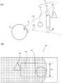
图2(A)是示意性地示出拍摄被检者的面部而得到的图像的图,图2(B)是示出被检者的面部的特征的概念图。FIG. 2(A) is a diagram schematically showing an image obtained by photographing the subject's face, and FIG. 2(B) is a conceptual diagram showing the characteristics of the subject's face.
图3(A)是用于说明被检者通过眼镜片进行观察的情况下的视野的范围的图,图3(B)是示意性地示出图3(A)的情况下的显示图像的一例的图。3(A) is a diagram for explaining the range of the visual field when the subject observes through spectacle lenses, and FIG. 3(B) schematically shows a display image in the case of FIG. 3(A) . Figure of an example.
图4(A)是用于说明被检者通过眼镜片进行观察的情况下的视野的范围的图,图4(B)是示意性地示出图4(A)的情况下的显示图像的一例的图。FIG. 4(A) is a diagram for explaining the range of the visual field when the subject observes through spectacle lenses, and FIG. 4(B) schematically shows a display image in the case of FIG. 4(A) . Figure of an example.
图5(A)是示出处于假想空间的物体的配置的概念图,图5(B)是示意性地示出图5(A)的情况下的显示图像的一例的图。FIG. 5(A) is a conceptual diagram showing the arrangement of objects in the virtual space, and FIG. 5(B) is a diagram schematically showing an example of a display image in the case of FIG. 5(A).
图6(A)是示出处于假想空间的物体的配置的概念图,图6(B)是示意性地示出图6(A)的情况下的显示图像的一例的图。FIG. 6(A) is a conceptual diagram showing the arrangement of objects in the virtual space, and FIG. 6(B) is a diagram schematically showing an example of a display image in the case of FIG. 6(A) .
图7是用于说明对假想视野的图像加进畸变的方法的概念图。FIG. 7 is a conceptual diagram for explaining a method of adding distortion to an image of a virtual field of view.
图8是用于说明对假想视野的图像加进畸变的方法的概念图。FIG. 8 is a conceptual diagram for explaining a method of adding distortion to an image of a virtual field of view.
图9(A)是示出没有方向依赖性的模糊图像的生成方法的一例的概念图。图9(B)是示出具有方向依赖性的模糊图像的生成方法的一例的概念图。FIG. 9(A) is a conceptual diagram showing an example of a method of generating a blurred image that is not directional dependent. FIG. 9(B) is a conceptual diagram showing an example of a method of generating a blurred image having direction dependence.
图10是用于说明基于调节力的卷积核的变化的概念图。FIG. 10 is a conceptual diagram for explaining a change in a convolution kernel based on accommodation power.
图11是示出包括一个实施方式的图像生成方法的眼镜片的制造方法的流程的流程图。FIG. 11 is a flowchart showing the flow of a method of manufacturing a spectacle lens including an image generation method of one embodiment.
图12是用于说明一个实施方式所涉及的程序的图。FIG. 12 is a diagram for explaining a program according to an embodiment.
具体实施方式Detailed ways
在以下的实施方式中,适当参照附图来说明图像生成装置等。在以下说明中,在记载为眼镜片的“上方”、“下方”、“上部”、“下部”等的情况下,设为基于在佩戴该眼镜片时从佩戴者观察的镜片内的位置关系。In the following embodiments, an image generating apparatus and the like will be described with reference to the drawings as appropriate. In the following description, when it is described as "upper", "lower", "upper", "lower", etc. of the spectacle lens, it is assumed to be based on the positional relationship in the lens observed from the wearer when the spectacle lens is worn .
图1是示出本实施方式的图像生成装置的概略结构的概念图。图像生成装置1具备拍摄部10、显示部20和信息处理部30。信息处理部30具备输入部31、通信部32、存储部33和控制部40。控制部40具备特征检测部41、参数计算部42、图像生成部43和显示控制部44。FIG. 1 is a conceptual diagram showing a schematic configuration of an image generation apparatus according to the present embodiment. The image generation device 1 includes an imaging unit 10 , a
图像生成装置1生成被检者S通过基于眼镜片的形状数据等的假想眼镜片目视显示部20的情况下的假想视野的图像(以下称为视野图像)。The image generation device 1 generates an image of a virtual field of view (hereinafter referred to as a field of view image) when the subject S visually views the
拍摄部10具备摄像机等拍摄装置,对被检者S的头部、特别是面部进行拍摄。只要能够从拍摄得到的图像中检测由后述的参数计算部42实施的处理所需的特征,则拍摄部10可以配置于任意的位置。入射到拍摄部10的光(图像)在经光电转换而变成表示光强度的信号之后,经A/D转换而输入到控制部40(箭头A1)。The imaging unit 10 includes an imaging device such as a camera, and images the head of the subject S, particularly the face. The imaging unit 10 may be disposed at any position as long as features required for processing by the parameter calculation unit 42 described later can be detected from the captured image. The light (image) incident on the imaging unit 10 is photoelectrically converted into a signal indicating light intensity, and then A/D converted and input to the control unit 40 (arrow A1 ).
显示部20具备液晶监视器等显示装置,通过显示控制部44的控制来显示图像生成部43所生成出的视野图像(箭头A2)。The
信息处理部30具备电子计算机等信息处理装置,进行视野图像的生成等所需的信息处理。The
此外,信息处理部30既可以像智能手机、笔记本电脑等那样,与拍摄部10以及/或者显示部20一体地构成,或者,也可以配置于从拍摄部10以及/或者显示部20物理性地分离的位置。进一步地,信息处理部30所进行的处理的一部分也可以由远程配置的电子计算机、服务器等进行,在信息处理部30中存储的数据的至少一部分也可以存储于远程配置的服务器等中。In addition, the
输入部31构成为包括鼠标、键盘、各种按钮以及/或者触摸面板等输入装置。输入部31从用户受理控制部40所进行的处理所需的信息等。The
通信部32构成为包括能够通过无线、有线连接而与因特网等网络进行通信的通信装置,接收被检者S的处方数据、眼镜片的形状数据,或者适当收发所需的数据。The
存储部33由非易失性的存储介质构成,存储被检者S的处方数据、眼镜片的形状数据等各种数据、用于控制部40执行处理的程序等。The
控制部40构成为包括CPU等处理器,执行在存储部33中存储的程序,是图像生成装置1的各动作的主体。控制部40基于拍摄部10进行拍摄得到的图像来生成视野图像,并使该视野图像显示于显示部20。The
控制部40的特征检测部41通过图像处理而从拍摄部10拍摄到的被检者S的头部的图像检测特征。在以下说明中,“特征”设为特征点、边缘、拐角以及适当包括它们的二维及三维的要素等通过图像处理能够与其他部分相区分的图像中的点、线或者部分。The feature detection unit 41 of the
图2(A)是示意性地示出拍摄部10拍摄被检者S的头部而得到的图像(以下称为被检者图像Is)的图。图2(A)的被检者图像Is是从正面拍摄被检者S而得到的图像,示出了被检者S的面部中的左眉毛BL、右眉毛BR、左眼EL、右眼ER、左瞳孔PL、右瞳孔PR、鼻N、嘴唇M、面部轮廓C等具有特征性的构造或者色彩等的部分。FIG. 2(A) is a diagram schematically showing an image obtained by imaging the head of the subject S by the imaging unit 10 (hereinafter referred to as the subject image Is). The subject image Is of FIG. 2(A) is an image obtained by photographing the subject S from the front, and shows the left eyebrow BL, right eyebrow BR, left eye EL, and right eye ER on the face of the subject S , the left pupil PL, the right pupil PR, the nose N, the lips M, the facial contour C and other parts with characteristic structures or colors.
图2(B)是示出特征检测部41所检测的特征F的图。特征检测部41使用FAST法、Canny法等图像处理而从被检者图像Is检测特征点、边缘以及/或者拐角等特征F。优选这些特征F的至少一部分是即使被检者S的面部相对于拍摄部10的朝向发生变化也能够检测的特征。特征检测部41基于在存储部33中存储的过去取得的特征F的信息等,决定所检测到的特征F对应于鼻N、面部轮廓C等中的哪个面部部分。此外,特征检测部41也可以将通过利用面部图像的数据集进行机器学习而得到的面部特征点检测模型检测为特征F。FIG. 2(B) is a diagram showing the feature F detected by the feature detection unit 41 . The feature detection unit 41 detects features F such as feature points, edges, and/or corners from the subject image Is using image processing such as the FAST method and the Canny method. Preferably, at least some of these features F are features that can be detected even if the orientation of the subject S's face with respect to the imaging unit 10 changes. The feature detection unit 41 determines to which part of the face the nose N, the facial contour C, and the like the detected feature F corresponds, based on the information of the feature F acquired in the past stored in the
在图2(B)中,作为特征检测部41从被检者图像Is检测的特征F,示出了与左眉毛BL对应的线状的特征FbL、与右眉毛BR对应的线状的特征FbR、与左眼EL的瞳孔中心对应的特征点FeL(以下称为左眼特征点)、与右眼ER的瞳孔中心对应的特征点FeR(以下称为右眼特征点)、与鼻尖对应的特征点Fna(以下称为鼻特征点)、与鼻N对应并且由从鼻根穿过鼻尖并向左右的外鼻孔分支出的线段构成的特征Fn、与上下的嘴唇M的红色部分的轮廓对应的特征Fm以及与面部轮廓C对应的线状的特征Fc。In FIG. 2(B) , as the feature F detected by the feature detection unit 41 from the subject image Is, a linear feature FbL corresponding to the left eyebrow BL and a linear feature FbR corresponding to the right eyebrow BR are shown , a feature point FeL corresponding to the pupil center of the left eye EL (hereinafter referred to as a left eye feature point), a feature point FeR corresponding to the pupil center of the right eye ER (hereinafter referred to as a right eye feature point), and a feature corresponding to the tip of the nose The point Fna (hereinafter referred to as the nose feature point), the feature Fn corresponding to the nose N and composed of a line segment extending from the root of the nose through the tip of the nose to the left and right external nostrils, corresponding to the contours of the red parts of the upper and lower lips M The feature Fm and the linear feature Fc corresponding to the facial contour C.
特征检测部41使构成各特征F的特征点的坐标的数据、将表现构成各特征F的线段的多个特征点的坐标关联起来而得到的数据以及与特征F对应的面部部分等存储于存储部33中。The feature detection unit 41 stores the data of the coordinates of the feature points constituting each feature F, the data obtained by correlating the coordinates of a plurality of feature points representing the line segments constituting each feature F, the face part corresponding to the feature F, and the like in the memory.
此外,只要后述的参数计算部42能够计算出期望的参数,则对表现各特征F的数据构造没有特别限定。In addition, the data structure expressing each feature F is not particularly limited as long as the parameter calculation unit 42 described later can calculate a desired parameter.
参数计算部42基于特征检测部41所检测到的被检者图像Is中的特征F的位置,计算被检者S的面部的位置以及面部的朝向等参数。在这里,“面部的朝向”能够通过与在图1中由R、P、Y的记号分别示意性地示出的旋转方向相对应的头部的横滚角、俯仰角、偏航角来描述。在这里,横滚角是绕在被检者S的前后方向上延伸的轴(z轴)的旋转角,俯仰角是绕在被检者S的左右方向上延伸的轴(x轴)的旋转角,偏航角是绕在被检者S的上下方向上延伸的轴(y轴)的旋转角。在图1中,用坐标轴900表示x轴、y轴以及z轴的方向与朝向。The parameter calculation unit 42 calculates parameters such as the position of the face of the subject S and the orientation of the face, based on the position of the feature F in the subject image Is detected by the feature detection unit 41 . Here, the "orientation of the face" can be described by the roll angle, pitch angle, and yaw angle of the head corresponding to the rotational directions schematically indicated by the symbols R, P, and Y in FIG. 1 , respectively. . Here, the roll angle is a rotation angle around an axis (z-axis) extending in the front-rear direction of the subject S, and the pitch angle is a rotation angle around an axis (x-axis) extending in the left-right direction of the subject S The yaw angle is a rotation angle around an axis (y-axis) extending in the up-down direction of the subject S. In FIG. 1 , the directions and orientations of the x-axis, the y-axis, and the z-axis are represented by the coordinate
此外,对坐标系的设置方式等、面部的朝向的数学表现方法没有特别限定。In addition, there is no particular limitation on the way of setting the coordinate system, and the method of mathematically expressing the orientation of the face.
对参数计算部42根据特征F计算面部的朝向的方法没有特别限定。例如,在Horprasert他们的论文(T.Horprasert,Y.Yacoob,and L.Davis,“Computing 3-D HeadOrientation from a Monocular Image Sequence,”Proceedings of the SecondInternational Conference on Automatic Face and Gesture Recognition(美国),IEEE,1996年,pp.242-247)中,示出根据包括眼睛端部(内眼角、外眼角)以及鼻尖的几个特征点来计算头部的横滚角、俯仰角、偏航角的方法。在这里,设为内眼角、外眼角处于同一直线上来进行计算。在由参数计算部42实施的被检者S的面部的朝向的计算中,除了在该论文中使用的、假定与面部的一部分对应的特征点处于规定的空间关系来进行计算的方法之外,还能够使用各种头部姿势推测(Head pose estimation)方法来根据被检者图像Is计算被检者S的面部的朝向。The method by which the parameter calculation unit 42 calculates the orientation of the face based on the feature F is not particularly limited. For example, in Horprasert their paper (T. Horprasert, Y. Yacoob, and L. Davis, "Computing 3-D HeadOrientation from a Monocular Image Sequence," Proceedings of the Second International Conference on Automatic Face and Gesture Recognition (USA), IEEE , 1996, pp.242-247), shows a method for calculating the roll angle, pitch angle, and yaw angle of the head according to several feature points including the end of the eye (inner canthus, outer canthus) and the tip of the nose . Here, the calculation is performed assuming that the inner canthus and the outer canthus are on the same straight line. In the calculation of the orientation of the face of the subject S by the parameter calculation unit 42, in addition to the method used in this paper, the calculation is performed assuming that feature points corresponding to a part of the face are in a predetermined spatial relationship, The orientation of the face of the subject S can also be calculated from the subject image Is using various head pose estimation methods.
参数计算部42能够根据特征检测部41所检测到的被检者图像Is中的特征F的位置、参数计算部42所计算出的面部的朝向以及被检者S的面部的一部分的长度的实测值,计算被检者S的位置。参数计算部42根据被检者图像Is中的左眼特征点FeL和右眼特征点FeR的坐标来计算左眼特征点FeL与右眼特征点FeR之间的距离PDi。参数计算部42基于所计算出的面部的朝向,将所计算出的图像上的距离PDi转换成从面部的正面观察的情况下的长度,基于该长度与实测到的瞳孔间距离(PD)的比较,计算被检者S与拍摄部10之间的距离。The parameter calculation unit 42 can measure the position of the feature F in the subject image Is detected by the feature detection unit 41 , the orientation of the face calculated by the parameter calculation unit 42 , and the length of a part of the face of the subject S. value, calculate the position of the subject S. The parameter calculation unit 42 calculates the distance PDi between the left-eye feature point FeL and the right-eye feature point FeR from the coordinates of the left-eye feature point FeL and the right-eye feature point FeR in the subject image Is. The parameter calculation unit 42 converts the calculated distance PDi on the image into a length when viewed from the front of the face, based on the calculated orientation of the face, based on the difference between the length and the measured interpupillary distance (PD). By comparison, the distance between the subject S and the imaging unit 10 is calculated.
例如,参数计算部42能够根据拍摄部10的拍摄元件的焦点面的纵横的尺寸以及焦距,求出已知的瞳孔间距离PD为图像上的距离PDi时的从拍摄部10至被检者S的距离。For example, the parameter calculation unit 42 can obtain the distance from the imaging unit 10 to the subject S when the known interpupillary distance PD is the distance PDi on the image from the vertical and horizontal dimensions of the focal plane of the imaging element of the imaging unit 10 and the focal length the distance.
此外,图像生成装置1也可以通过具备通过ToF(Time of Flight,飞行时间)方式进行测距并拍摄距离图像的ToF摄像机或者立体摄像机等除使用从被摄体图像Is检测到的特征F以外的方法来测定从拍摄部10至被检者S的距离。In addition, the image generation device 1 may be provided with a ToF camera or a stereo camera that performs distance measurement by the ToF (Time of Flight) method and captures distance images in addition to using the feature F detected from the subject image Is. method to measure the distance from the imaging unit 10 to the subject S.
如图1所示,参数计算部42根据所计算出的被检者S和拍摄部10之间的距离Ez与预先确定的拍摄部10和显示部20之间的距离Cz之和,计算被检者S与显示部20之间的距离。另外,参数计算部42根据被检者S与拍摄部10之间的距离Ez以及从拍摄部10看去的被检者S的眼睛E的方向,计算被检者S的眼睛E与拍摄部10之间的y轴方向的距离Ey。参数计算部42根据该距离Ey以及预先确定的显示部20的位置O与拍摄部10之间的y轴方向的距离Cy,计算以显示部20为基准的眼睛E的y轴方向的位置。参数计算部42对x轴方向,也与y轴方向同样地进行计算,计算以显示部20为基准的眼睛E的三维位置。关于表示拍摄部10与显示部20的位置关系的距离Cy、Cz等,由用户经由输入部31输入,或者使用预先存储在存储部33中的数值。As shown in FIG. 1 , the parameter calculation unit 42 calculates the subject based on the sum of the calculated distance Ez between the subject S and the imaging unit 10 and the predetermined distance Cz between the imaging unit 10 and the
此外,在拍摄部10的拍摄方向与显示部20的显示画面的法线方向不同的情况下,预先测定该拍摄方向与该法线方向所形成的角度,并由图像生成装置1的用户(以下简称为“用户”)等输入。参数计算部42能够基于所输入的该角度,将根据被检者图像Is计算出的被检者S的面部及眼睛的三维位置以及面部的朝向校正成以显示部20为基准的值。In addition, when the photographing direction of the photographing unit 10 is different from the normal direction of the display screen of the
图像生成部43基于参数计算部42所计算出的被检者S与显示部20之间的距离以及被检者S的面部的朝向,生成被检者S通过眼镜片目视显示部20的情况下的假想视野的图像(视野图像)。如后面所述,视野图像是指假设在显示部20的位置处存在假想物体,被检者S对显示部20(即,对假想物体)从各个位置目视时,通过假想眼镜片从该位置目视该假想物体的情况下的视野的图像。视野图像构成为跟随着被检者S的面部的朝向等而视野图像中的眼镜片的位置以及朝向进行跟随的实时动画,也可以在记录包括视野图像的动画之后进行重放。The image generation unit 43 generates a case where the subject S visually sees the
图像生成部43取得假想空间中的各物体的位置、形状、纹理等数据(以下称为假想空间描述数据),构建假想空间。对于在假想空间描述数据中包括的各值,基于在存储部33中存储的信息、经由通信部32从外部取得的信息来进行设定,或者基于称为用户)的输入来进行设定。对假想空间中的物体的配置的形态没有特别限定,但如果像本实施方式那样将假想物体配置于显示部20的位置,则对于目视显示部20的被检者S来说容易掌握位置、大小,所以是优选的。进一步地,以配置于显示部20的位置的假想物体为基准,被检者S容易掌握配置于假想空间并显示于显示部20的其他假想物体看起来如何,所以是优选的。The image generation unit 43 acquires data (hereinafter referred to as virtual space description data) of the position, shape, texture, and the like of each object in the virtual space, and constructs the virtual space. Each value included in the virtual space description data is set based on information stored in the
对基于假想空间描述数据的假想空间的表现方法没有特别限定,例如,设定好表示配置于假想空间的各物体(几何体)在何处按什么朝向配置的位置信息,并适当设定好关于几何体的表面处的光的反射率以及透射率、颜色、纹理的信息等。关于几何体的细微的立体构造等,能够利用作为纹理的几何体的平面的信息适当进行置换来表现。假想空间描述数据也可以包括与照亮假想空间的照明相关的数据。与照明相关的数据适当具备照明的位置、照明的光的颜色、波长分布、光的强度等。The representation method of the virtual space based on the virtual space description data is not particularly limited. For example, position information indicating where and in what direction each object (geometric body) arranged in the virtual space is set, and the geometric body is appropriately set. The reflectance and transmittance of the light at the surface, the information of the color, texture, etc. A fine three-dimensional structure of a geometric body, etc., can be expressed by appropriate replacement using information on the plane of the geometric body as a texture. The hypothetical space description data may also include data related to lighting that illuminates the hypothetical space. The data related to the illumination includes the position of the illumination, the color of the illumination light, the wavelength distribution, the intensity of the light, and the like as appropriate.
图像生成部43取得关于在被检者S目视显示部20时假想地佩戴的眼镜片的数据(以下称为眼镜片描述数据)。对于在眼镜片描述数据中包括的各值,基于在存储部33中存储的信息、经由通信部32从外部取得的信息来进行设定,或者基于来自用户的对被检者S的处方数据以及镜片的种类的输入来进行设定。眼镜片描述数据包括眼镜片的形状数据、眼镜片的材料特性数据。眼镜片的形状数据包括眼镜片的外形信息、中心厚度、眼镜片的物体侧及眼球侧的前后两面以及周围表面的形状数据等。眼镜片的材料特性数据包括折射率等数据。The image generation unit 43 acquires data (hereinafter referred to as spectacle lens description data) about the spectacle lenses that the subject S wears virtually when viewing the
此外,眼镜片描述数据也可以包括表示通过眼镜片进行观察时的像差量的值。该像差量优选包括关于球面像差、像散、彗差等的像差量。该像差量是基于处方数据、镜片的形状、镜片的材料、后述的佩戴参数、与注视点的距离以及/或者眼睛的调节力等预先根据光线追踪而计算出的数值,用矢量、矩阵等形式来适当表现。Further, the spectacle lens description data may include a value indicating the amount of aberration when observed through the spectacle lens. The aberration amount preferably includes aberration amounts regarding spherical aberration, astigmatism, coma, and the like. The amount of aberration is a value calculated in advance by ray tracing based on prescription data, lens shape, lens material, wearing parameters described later, distance from the gaze point, and/or eye accommodation power, etc. and other forms to perform appropriately.
图像生成部43设定被检者S佩戴眼镜片时的被检者S与眼镜片的相对位置(以下称为眼镜片位置)。眼镜片位置优选基于用户所输入的与眼镜片位置相关的数据(以下称为眼镜片位置数据)来设定。眼镜片位置数据包括在被检者S佩戴眼镜片时通过实测等得到并输入的与眼镜片位置相关的佩戴参数,该佩戴参数例如包括角膜顶点间距离、前倾角、挠角等。在用户以关于被检者S不使用眼镜片位置数据的方式进行了输入的情况下,图像生成部43基于成为设计眼镜片时的基准的眼镜片与眼球的位置关系来设定眼镜片位置。The image generation unit 43 sets the relative position of the subject S and the spectacle lenses when the subject S wears the spectacle lenses (hereinafter referred to as the spectacle lens position). The spectacle lens position is preferably set based on data related to the spectacle lens position (hereinafter referred to as spectacle lens position data) input by the user. The spectacle lens position data includes wearing parameters related to the spectacle lens position obtained and input through actual measurement when the subject S wears the spectacle lenses, for example, the wearing parameters include the distance between corneal vertices, the anteversion angle, the deflection angle, and the like. When the user inputs the spectacle lens position data about the subject S without using the spectacle lens position data, the image generation unit 43 sets the spectacle lens position based on the positional relationship between the spectacle lens and the eyeball that is a reference when designing the spectacle lens.
图像生成部43在参数计算部42基于通过由拍摄部10实施的拍摄而得到的被检者图像Is而计算出被检者S的眼睛E的位置以及面部的朝向后,生成从该眼睛E的位置目视处于显示部20的位置的假想物体的情况下的视野图像。图像生成部43根据眼睛E的位置、面部的朝向、眼镜片位置、眼镜片描述数据以及假想空间描述数据,生成通过眼镜片目视假想物体的情况下的视野图像。The image generation unit 43 generates an image obtained from the eye E after the parameter calculation unit 42 calculates the position of the eye E and the orientation of the face of the subject S based on the subject image Is obtained by the imaging performed by the imaging unit 10 . The position is a visual field image when the virtual object at the position of the
图3(A)是用于说明视野图像的概念图。在图3(A)中,将眼镜片9L、9R设为基于眼镜片描述数据的假想眼镜片来示出。被检者S的眼球EbL、EbR目视显示部20,右眼球EbR的光轴Ax穿过显示部20的中心O。在显示部20中显示有视野图像21,在视野图像21中示出了3个假想物体V(Vo、V1、V2)的图像。眼镜片9L、9R假想地配置于左眼球EbL以及右眼球EbR的前方的眼镜片位置。FIG. 3(A) is a conceptual diagram for explaining the visual field image. In FIG. 3(A) , the
在图3(A)中,虚线L1、L2分别示意性地示出从右眼球EbR通过眼镜片9R能够观察到的视野的范围的左端以及右端。即,对于被检者S,显示部20的左侧是通过眼镜片9R能够目视到的范围,但关于显示部20的右侧的一部分,是通过眼镜片9R无法目视到的范围。In FIG. 3(A) , broken lines L1 and L2 schematically show the left end and the right end of the range of the visual field that can be observed from the right eyeball EbR through the
图3(B)是示意性地示出图3(A)的情况下的视野图像21的图。视野图像21的附加了阴影线的部分22是被检者S通过假想眼镜片9R目视显示部20的情况下的视野的图像。视野图像21的未附加阴影线的部分23是被检者S不通过假想眼镜片9R而目视显示部20的情况下的视野的图像。关于在图3(A)中通过眼镜片9R无法目视到的视野图像21的右侧的一部分区域,显示被检者S用肉眼看到的视野的图像。这样,图像生成部43基于被检者S的视野中的眼镜片9L、9R的区域来生成视野图像21。FIG. 3(B) is a diagram schematically showing the
此外,视野图像21既可以基于左眼或者右眼中的任一方的视野来生成,也可以生成为基于主视眼的程度等使关于两眼的视野的视野图像局部地错开并合成而得到的合成图像。另外,在本实施方式中,参数计算部42计算眼睛的位置,图像生成部43将该眼睛的位置设为视点而生成视野图像,但视点也可以并非严格地与眼睛的位置相重合,例如能够像将两眼的中央的位置设为视点位置等这样适当设定。In addition, the
图4(A)是示出被检者S使头部从图3(A)的状态偏向右侧后的状态的概念图。在图4(A)以及图4(B)中,关于与图3(A)以及图3(B)相同的部分,用同一标号来参照,适当省略说明。由虚线L1、L2分别示意性地示出的、从右眼球EbR通过眼镜片9R能够观察到的视野的范围的左端以及右端朝向显示部20往右侧移动。即,被检者S通过眼镜片9R目视显示部20的右侧,但关于显示部20的左侧的一部分,通过眼镜片9R无法目视到。FIG. 4(A) is a conceptual diagram showing a state in which the subject S deflects the head from the state of FIG. 3(A) to the right. In FIGS. 4(A) and 4(B) , the same parts as those in FIGS. 3(A) and 3(B) are referred to by the same reference numerals, and descriptions are appropriately omitted. The left end and the right end of the range of the visual field that can be observed from the right eyeball EbR through the
图4(B)是示意性地示出图4(A)的情况下的视野图像21的图。关于在图4(A)中通过眼镜片9R无法目视到的左侧的一部分区域,显示被检者S用肉眼看到的视野的图像。这样,图像生成部43在被检者S使眼睛的位置、面部的朝向发生了变化的情况下,基于与此相伴的视野中的眼镜片9L、9R的区域的变化来生成视野图像21。FIG. 4(B) is a diagram schematically showing the
图5(A)是用于说明视野图像21中的视场角的调整的概念图。在本实施方式中,以在显示部20的位置处配置假想物体(以下称为基准物体Vo)的方式构建假想空间。在这里,如果被检者S与显示部20之间的距离变化,则被检者S的视野中的基准物体Vo的大小本来也会变化,但为了以容易观察假想物体间的视觉观感的关系的方式进行显示,图像生成部43以即使在这样的情况下基准物体Vo在视野图像21中的大小也大致恒定的方式,调整关于视野图像21的视场角。FIG. 5(A) is a conceptual diagram for explaining adjustment of the viewing angle in the
在图5(A)中,作为假想物体V,示意性地示出了基准物体Vo、假想物体V1、假想物体V2。设为基准物体Vo处于显示部20(由虚线示意性地示出)的位置来构建假想空间。被检者S的视野示意性地示为被从被检者S的眼睛E延伸的单点划线L3以及L4夹着的区域。In FIG. 5(A), as the virtual object V, a reference object Vo, a virtual object V1, and a virtual object V2 are schematically shown. An imaginary space is constructed assuming that the reference object Vo is at the position of the display unit 20 (schematically shown by a dotted line). The visual field of the subject S is schematically shown as a region sandwiched by the one-dot chain lines L3 and L4 extending from the eyes E of the subject S.
图5(B)是示出在图5(A)的情况下在显示部20中显示的视野图像21的图。如图5(A)所示,从被检者S侧起由近到远地按假想物体V1、基准物体Vo、假想物体V2的顺序排列,所以,在视野图像21中,以假想物体V1处于最近前、假想物体V2处于最后方的方式重叠示出。如上所述,图像生成部43以使基准物体Vo的大小大致恒定的方式调整与视野图像21对应的视场角,所以,即使视点位置变化,视野图像21中的基准物体Vo的宽度Lo也大致恒定。FIG. 5(B) is a diagram showing the
图6(A)是示出与图5(A)的情况相比被检者S与显示部20之间的距离较短的情况的概念图。在图6(A)以及图6(B)中,关于与图5(A)以及图5(B)相同的部分,用同一标号来参照,适当省略说明。FIG. 6(A) is a conceptual diagram illustrating a case where the distance between the subject S and the
图6(B)是示出在图6(A)的情况下在显示部20中显示的视野图像21的图。由于被检者S与基准物体Vo之间的距离与图5(A)所示的情况相比变短,所以,被检者S的视野中的基准物体Vo的大小本来应变大,但视野图像21中的基准物体Vo的大小被调整为大致恒定,因此,视野图像21中的基准物体Vo的宽度Lo也保持于大致恒定的值。换言之,无论视点位置如何,视野图像21中的基准物体Vo的大小都与显示部20的显示画面的大小处于恒定的关系。FIG. 6(B) is a diagram showing the
图像生成部43在视野图像21的生成中,将被检者S的眼睛的位置设为视点位置,通过透视投影等绘制假想空间而生成投影图像。在投影图像中,与视野图像21相比较,未加进有由眼镜片9L、9R等引起的后述的模糊、畸变。图像生成部43在生成投影图像时,以配置于显示部20的位置的假想物体Vo的大小无论视点位置如何都大致恒定的方式来调整视场角。换言之,图像生成部43在生成视野图像21时,以视野图像21的视场角无论视点位置如何都与显示部20的显示画面的大小相对应的方式来生成视野图像21。由此,基准物体Vo不会大幅变化,所以,如图5(B)、图6(B)所示,容易捕捉到在假想空间中处于基准物体Vo的周围的假想物体V1以及V2的视觉观感根据视点位置如何变化。In the generation of the
图像生成部43在生成投影图像之后,进行将由假想眼镜片9(在不区分眼镜片9L、9R的左右地指称的情况下,称为眼镜片9)产生的畸变加进到该投影图像的图像处理。After generating the projected image, the image generating unit 43 adds the distortion generated by the virtual spectacle lens 9 (referred to as the
在以下的实施方式中,“畸变”表示将对象物识别为形状与实际形状不同的像,主要指对象物的像在纵横倾斜等任意的方向上伸缩。在“畸变”中,适当包括歪曲像差(distortion),在本实施方式中,主要设想由于通过如渐进光焦度镜片的镜片面那样光焦度、像散变化的面观察对象物而引起的对象物的像的伸缩。In the following embodiments, "distortion" means that the object is recognized as an image whose shape is different from the actual shape, and mainly means that the image of the object expands and contracts in arbitrary directions such as vertical, horizontal and inclination. "Distortion" includes distortion aberration as appropriate, and in the present embodiment, it is mainly assumed that the object is observed through a surface in which the refractive power and astigmatism change, such as the lens surface of a progressive-power lens. The expansion and contraction of the image of the object.
图7是用于说明对投影图像加进畸变的方法的概念图。图像生成部43通过从回旋点Cr透过眼镜片9并将眼镜片9的表面的点P1至注视点Pt连接的光线追踪来计算将被检者S观察显示部20的显示画面S20时的视网膜与显示画面S20上的注视点Pt连接的光程。回旋点Cr的位置优选使用与被检者S的面部的形状相关的实测得到的数据来设定,但也能够使用在设计眼镜片9时设想的回旋点的位置、一般的位置来设定。FIG. 7 is a conceptual diagram for explaining a method of adding distortion to a projected image. The image generation unit 43 calculates the retina when the subject S observes the display screen S20 of the
此外,在光线追踪的计算中,也可以追踪入射到视网膜的各点或者从视网膜的各点射出的光线。In addition, in the calculation of ray tracing, light rays incident to or emanating from each point of the retina can also be traced.
图像生成部43在眼镜片9的旁边设定假想的面(以下称为假想面S1)。假想面S1优选以如下方式设定:在被检者S观察正面时,或者在眼球Eb观察眼镜片9的拟合点时,假想面S1与显示画面S20大致平行,或者眼球Eb的光轴Ax与假想面S1大致垂直地交叉。图像生成部43对穿过假想面S1上的一部分的点P0的光线进行光线追踪,根据基于该光线追踪的结果计算出的视野图像21的局部畸变的程度,对投影图像加进畸变。The image generation unit 43 sets an imaginary surface (hereinafter referred to as an imaginary surface S1 ) beside the
图8是示出基于光线追踪的视野图像21的局部畸变的计算方法的图。为了容易理解说明,将假想面S1以及显示画面S20用与x轴以及y轴(参照坐标系902)平行的格子状的线分割开而示出,在显示画面S20的位置处,配置有通过透视投影等绘制假想空间而得到的投影图像。在该投影图像中包含假想物体V3。FIG. 8 is a diagram showing a calculation method of the local distortion of the
图像生成部43通过光线追踪,计算穿过回旋点Cr与假想面S1上的点P01、P02、P03、P04等坐标点的光线所入射的显示画面S20上的分别对应的点Pt1、Pt2、Pt3、Pt4等的位置。The image generation unit 43 calculates the corresponding points Pt1 , Pt2 , and Pt3 on the display screen S20 , respectively, on the display screen S20 on which the rays passing through the gyroscope point Cr and the coordinate points such as the points P01 , P02 , P03 , and P04 on the virtual plane S1 are incident by ray tracing. , Pt4, etc.
如图7所示,图像生成部43通过光线追踪来计算从眼镜片9的显示部20侧的面上的点P1向穿过点P1的光线所入射的显示画面S20上的点Pt的矢量Vt。如果将点P1的坐标表示为P1(x1,y1,z1)、将点Pt的坐标表示为Pt(xt,yt,zt)、将矢量Vt表示为Vt(vx,vy,vz)(参照坐标系901),则将a设为(zt-z1)/vz,点P的x坐标xt与y坐标yt如以下的式(1)所示地表示。As shown in FIG. 7 , the image generation unit 43 calculates, by ray tracing, a vector Vt from the point P1 on the surface of the
xt=x1+a*vx,yt=y1+a*vy…式(1)xt=x1+a*vx, yt=y1+a*vy... Formula (1)
近似地,zt-z1能够使用被检者S与显示部20之间的距离,所以,图像生成部43能够基于矢量Vt来计算点P的x坐标xt与y坐标yt。点P0与点P1可以通过光线追踪而对应起来,近似地,点P0的x坐标以及y坐标也能够使用与点P1相同的值。图像生成部43能够通过这样的方法,将点P01~P04与点Pt1~t4(图8)对应起来。Approximately, since zt-z1 can use the distance between the subject S and the
此外,眼镜片描述数据或者眼镜片位置数据等与眼镜片9相关的数据也可以包括与眼镜片9关联起来的表示从眼镜片9向显示部20的视线的方向的参数即上述矢量Vt。由此,能够减少生成视野图像21时的运算处理的量。In addition, the data related to the
在图8中,在假想面S1上由点P01、P02、P03以及P04包围起来的四边形的部分区域(由双点划线包围起来的区域)R1对应于在显示画面S20上由点Pt1、Pt2、Pt3以及Pt4包围起来的部分区域R2。因此,图像生成部43以使与从假想空间绘制得到的投影图像的部分区域R2对应的部分包含在部分区域R1中的方式,使该投影图像进行伸缩。在图8的例子中,显示画面S20上的部分区域R2对应于y轴方向的宽度较小的假想面S1上的部分区域R1,基于这一点,对与部分区域R2对应的假想物体V3的图像以在y轴方向上缩小的方式进行加工。换言之,关于未进行光线追踪的眼镜片9上的点,加进通过线性插值而确定的畸变。In FIG. 8 , a quadrangular partial area (area surrounded by a two-dot chain line) R1 surrounded by points P01 , P02 , P03 and P04 on the imaginary plane S1 corresponds to points Pt1 and Pt2 on the display screen S20 A partial region R2 surrounded by , Pt3 and Pt4. Therefore, the image generation unit 43 expands and contracts the projected image so that the portion corresponding to the partial region R2 of the projected image drawn from the virtual space is included in the partial region R1. In the example of FIG. 8 , the partial area R2 on the display screen S20 corresponds to the partial area R1 on the imaginary plane S1 having a small width in the y-axis direction. Based on this, the image of the virtual object V3 corresponding to the partial area R2 is Machining is performed so as to shrink in the y-axis direction. In other words, with respect to points on the
如上所述,图像生成部43基于从被检者S的眼睛射出的光的从眼镜片9的出射方向,计算视野图像21中的局部畸变的方向、量,生成加进有该畸变的视野图像21。由此,图像生成部43即使不针对与眼镜片9的面对应的全部坐标点进行光线追踪,也能够生成加进有畸变的视野图像21。因此,图像生成部43能够高速地生成加进有畸变的视野图像21,能够生成由该视野图像21构成的帧速率更高的动态图像。As described above, the image generation unit 43 calculates the direction and amount of local distortion in the
图像生成部43在对绘制假想空间而得到的、从视点位置观察假想空间看到的投影图像加进畸变之后,进行将由假想眼镜片9产生的模糊加进到该投影图像的图像处理。The image generation unit 43 adds distortion to the projected image obtained by rendering the virtual space and viewed from the viewpoint position in the virtual space, and then performs image processing of adding blur caused by the
在以下的实施方式中,“模糊”是指在以比适于视觉辨认对象物的分辨率低的分辨率识别该对象物时引起的对象物的细节的消失。更具体来说,“模糊”主要指在以散焦状态(焦点发生了偏移的状态)拍摄到的图像、在基于来自对象物的光的眼睛光学系统的光学像差的成像面与视网膜偏移时识别到的像中观察到的轮廓、图案的不清楚化。In the following embodiments, "blur" refers to the disappearance of details of the object caused when the object is recognized at a resolution lower than the resolution suitable for visually recognizing the object. More specifically, "blur" mainly refers to an image captured in a defocused state (a state in which the focal point is shifted), and the difference between the image plane and the retina due to the optical aberration of the optical system of the eye due to the light from the object. Contours and patterns observed in time-lapse images are obscured.
图9(A)以及图9(B)是用于说明对图像加进模糊的方法的一例的概念图。图9(A)是示出从加进模糊之前的图像Bo生成对模糊没有方向依赖性的情况下的模糊图像B1时的图像处理的概念图。在该情况下的模糊图像B1例如是基于没有像散的情况下的由光焦度误差导致的模糊而生成出的。9(A) and 9(B) are conceptual diagrams for explaining an example of a method of blurring an image. FIG. 9(A) is a conceptual diagram illustrating image processing when a blurred image B1 in which there is no direction dependence on blurring is generated from the image Bo before blurring is added. The blurred image B1 in this case is generated based on, for example, blur caused by a power error in the case where there is no astigmatism.
模糊图像B1能够通过以点分布函数(Point Spread Function;PSF)为卷积核对图像中的各像素的像素值进行卷积积分而取得。在圆中描绘有X的记号表示卷积积分。当通过没有方向依赖性的点分布函数PSF1对加进模糊之前的图像Bo进行卷积积分后,能够得到如模糊图像B1所示地各点均匀地模糊那样的图像。模糊图像B1是非方向依赖性的模糊图像B1。卷积积分在由计算机实施的离散计算中,相当于进行以3×3、5×5等矩阵(参照图10,下面称为模糊卷积核矩阵)为卷积核的卷积处理。The blurred image B1 can be obtained by convolving and integrating the pixel values of each pixel in the image using a point distribution function (PSF) as a convolution check. A symbol with an X drawn in a circle represents a convolution integral. When the image Bo before blurring is convolved and integrated by the point distribution function PSF1 having no direction dependence, an image in which each point is uniformly blurred as shown in the blurred image B1 can be obtained. The blurred image B1 is a direction-independent blurred image B1. The convolution integral is equivalent to performing a convolution process using a matrix such as 3×3 or 5×5 (refer to FIG. 10 , hereinafter referred to as a fuzzy convolution kernel matrix) as a convolution kernel in discrete computation performed by a computer.
图9(B)是示出生成对模糊有方向依赖性的情况下的模糊图像B2时的图像处理的概念图。该情况下的模糊图像B2是对由像散和光焦度误差导致的模糊进行模拟而得到的。FIG. 9(B) is a conceptual diagram illustrating image processing when a blurred image B2 is generated when blurring is directional dependent. The blurred image B2 in this case is obtained by simulating blurring caused by astigmatism and power error.
当通过具有方向依赖性(斜45度方向)的点分布函数PSF2对加进模糊之前的像Bo进行卷积积分后,能够得到如模糊图像B2所示地各点朝向斜45度方向更加强烈地模糊的图像。模糊图像B2是方向依赖性的模糊图像B2。When the point distribution function PSF2 with direction dependence (oblique 45-degree direction) is used to convolve and integrate the image Bo before blurring is added, it can be obtained that each point is more strongly oriented in the oblique 45-degree direction as shown in the blurred image B2. Blurred image. The blurred image B2 is a direction-dependent blurred image B2.
在图9(A)、图9(B)的例子中,示出对加进模糊之前的图像Bo的整体使用相同的点分布函数进行卷积处理来生成模糊图像B1、B2的例子。但是,图像生成部43能够在投影图像的各位置处,以对应于适当不同的点分布函数的模糊卷积核矩阵作为卷积核进行卷积处理而生成视野图像21。9(A) and 9(B) show examples in which blurred images B1 and B2 are generated by performing convolution processing on the entire image Bo before blurring using the same point distribution function. However, the image generating unit 43 can generate the
图像生成部43经由输入部31或通信部32,或者从在存储部33中存储的被检者S的过去的数据,参照被检者S的眼镜片的处方数据,取得球面度数、散光度数以及散光轴的数据等与眼睛的光焦度相关的数据。图像生成部43根据所取得的与眼睛的光焦度相关的数据以及观察显示部20的中心O(图1)等规定位置时的眼镜片9的光焦度,设定被检者S使焦点与显示部20重合时的模糊卷积核矩阵。The image generation unit 43 refers to the prescription data of the spectacle lenses of the subject S via the
图像生成部43取得被检者S的调节力。被检者S的调节力例如基于调节力的大小,通过以屈光度(D)等为单位的数值(以下称为调节力参数)来设定。调节力参数既可以由用户从输入部31输入,也可以根据被检者S的处方数据中的年龄,基于已知的数据来设定,在渐进光焦度镜片等的情况下,处方数据也可以基于加入度等来计算。The image generation unit 43 acquires the accommodation power of the subject S. FIG. The accommodation power of the subject S is set based on, for example, the magnitude of the accommodation power by a numerical value (hereinafter referred to as accommodation power parameter) in units of diopter (D) or the like. The adjustment power parameter may be input from the
图像生成部43基于根据被检者S的球面度数、散光度数以及散光轴的数据计算出的光焦度、被检者S目视显示部20的中心O等时的眼镜片9的光焦度及像散、被检者S与显示部20之间的距离、假想空间的物体的位置以及基于调节力参数的调节力,通过光线追踪求出像差量,设定模糊卷积核矩阵K。如果调节力大,则眼睛的光焦度的变化量大,所以,与眼睛的光焦度的变化量相匹配地,例如每隔0.25D等任意的光焦度而设定不同的模糊卷积核矩阵K。The image generation unit 43 is based on the refractive power calculated from the data of the spherical power, the astigmatic power, and the astigmatic axis of the subject S, the refractive power of the
图10是示出光焦度发生了变化时的模糊卷积核矩阵K的变化的概念图。当被检者S通过调节使眼球Eb的光焦度增大时,模糊卷积核矩阵K按模糊卷积核矩阵K1、K2、K3、K4、K5、K6的顺序变化。在图10中,示出了模糊卷积核矩阵K是3×3的情况,重叠地示意性示出与模糊卷积核矩阵K1、K2、K3、K4、K5以及K6分别对应的点分布函数PSF1、PSF2、PSF3、PSF4、PSF5以及PSF6。FIG. 10 is a conceptual diagram showing the change of the blur kernel matrix K when the refractive power is changed. When the optical power of the eyeball Eb is increased by the adjustment of the subject S, the blur kernel matrix K changes in the order of the blur kernel matrices K1 , K2 , K3 , K4 , K5 , and K6 . In FIG. 10 , the case where the fuzzy convolution kernel matrix K is 3×3 is shown, and the point distribution functions corresponding to the fuzzy convolution kernel matrices K1 , K2 , K3 , K4 , K5 and K6 , respectively, are superimposed and schematically shown. PSF1, PSF2, PSF3, PSF4, PSF5, and PSF6.
模糊卷积核矩阵K4是中央的数值为1.00并且不产生模糊的卷积核。被检者S考虑在注视点处,在调节力的范围内,按最不产生模糊的光焦度进行调节。因此,图像生成部43在基于根据被检者S的调节力能够实现的光焦度的模糊卷积核矩阵K中,将模糊最少、即模糊卷积核矩阵K的最中央的要素的数值最大的模糊卷积核矩阵K4设定为与显示部20的中心O对应的视野图像21的位置的卷积核。图像生成部43取得与该模糊卷积核矩阵K4对应的被检者S的光焦度(以下称为调节后光焦度)的值。The blur kernel matrix K4 is a kernel with a central value of 1.00 and no blurring. The subject S considers that at the fixation point, within the range of the accommodation power, the adjustment is performed with the power that produces the least blur. Therefore, the image generation unit 43 maximizes the numerical value of the blur kernel matrix K based on the refractive power that can be realized according to the accommodation power of the subject S, that is, the most central element of the blur kernel matrix K with the least blur. The blur convolution kernel matrix K4 is set as the convolution kernel at the position of the
图像生成部43当在所设想的模糊卷积核矩阵K中有多个最中央的要素的数值取最大的值的模糊卷积核矩阵K的情况下,将与调节量最小的情况对应的模糊卷积核矩阵K设定为与显示部20的中心O对应的视野图像21的位置的卷积核。When there is a blur kernel matrix K in which the numerical value of a plurality of the most central elements takes the largest value in the assumed blur kernel matrix K, the image generation unit 43 creates a blur corresponding to the case where the adjustment amount is the smallest. The convolution kernel matrix K is set as a convolution kernel at the position of the
图像生成部43基于所取得的调节后光焦度、散光度数及散光轴、假想空间内的各点的位置以及在目视该各点时视线透过的眼镜片9的位置的光焦度及像散,计算视野图像21的各点的模糊卷积核矩阵K。The image generating unit 43 is based on the obtained adjusted refractive power, astigmatism power, and astigmatic axis, the position of each point in the virtual space, and the refractive power and Astigmatism, the blur kernel matrix K of each point of the
此外,在视野图像21中,关于不通过眼镜片9而观察的部分,既可以基于如上所述得到的被检者S的调节力来计算模糊卷积核矩阵K,也可以基于被检者S的肉眼的验光数据来加进模糊。In addition, in the
图像生成部43对从配置于假想空间的假想物体V上的各点射出、透过眼镜片9并入射到眼睛E的视网膜的光线进行光线追踪。在这里,图像生成部43基于上述得到的调节后调节力来设定眼球模型中的镜片的参数。眼球模型可以适当利用基于过去测定出的眼球的数据构建的模型。图像生成部43能够根据在光线追踪中入射到视网膜的各点的各光线的收敛位置,计算视野图像21的各点处的像差量。图像生成部43基于视野图像21的各点处的像差量来设定该各点的模糊卷积核矩阵K。The image generation unit 43 performs ray tracing on the light rays emitted from each point on the virtual object V arranged in the virtual space, transmitted through the
此外,也可以做成图像生成部43取得将在眼镜片9的各点处基于眼镜片形状数据以及眼镜片位置数据等并通过光线追踪预先计算出的模糊卷积核矩阵K与眼镜片9关联起来而得到的数据的结构。In addition, the image generation unit 43 may be configured to obtain a blur convolution kernel matrix K calculated in advance by ray tracing at each point of the
当设定了与视野图像21的各点对应的模糊卷积核矩阵K后,图像生成部43以这些模糊卷积核矩阵K作为卷积核,对表示上述加进有畸变的图像的像素值的矩阵进行卷积处理,生成视野图像21。After the blur convolution kernel matrix K corresponding to each point of the
此外,也可以针对基于视点位置绘制假想空间而得到的二维图像,首先通过使用模糊卷积核矩阵K的上述方法加进模糊之后,再加进畸变。In addition, the two-dimensional image obtained by drawing the virtual space based on the viewpoint position may first be blurred by the above method using the blur kernel matrix K, and then the distortion may be added.
显示控制部44(图1)控制由图像生成部43生成出的视野图像21往显示部20的显示画面的显示。显示控制部44基于拍摄部10依次拍摄到的被检者图像Is,将图像生成部43依次生成出的视野图像21依次显示于显示部20。The display control unit 44 ( FIG. 1 ) controls the display of the
被检者S能够一边从各个位置目视显示于显示部20的视野图像21,一边通过假想眼镜片9体验处于显示部20的位置的基准物体Vo等看起来如何。图像生成装置1能够构成为用于被检者S基于这样的体验来选择要佩戴的眼镜片的眼镜片选择系统。The subject S can experience how the reference object Vo or the like at the position of the
进一步地,被检者S能够通过假想眼镜片9,体验在假想空间中处于基准物体Vo的周围的其他假想物体V1、V2如何映在视野中。眼镜片的佩戴者有时特别在意渐进光焦度镜片上的从注视点离开的点处的视觉观感、单焦点镜片上的镜片的边缘部处的视觉观感。本实施方式的图像生成装置1作为进行佩戴眼镜片的情况下的这样的视觉观感的仿真的装置特别适合。Furthermore, the subject S can experience how the other virtual objects V1 and V2 surrounding the reference object Vo in the virtual space are reflected in the field of view through the
图11是示出使用本实施方式的图像生成装置的图像生成方法的流程的流程图。在步骤S1001中,为了使被检者S能够不费力地观察在显示部20中显示的图像,通过被检者S佩戴矫正镜片等来矫正被检者S的视力。作为矫正镜片,也可以是被检者S通常佩戴的眼镜片。当步骤S1001结束后,开始步骤S1003。在步骤S1003中,图像生成部43设定配置于假想空间的假想物体V,构建假想空间。当步骤S1003结束后,开始步骤S1005。FIG. 11 is a flowchart showing the flow of an image generation method using the image generation apparatus of the present embodiment. In step S1001 , the eyesight of the subject S is corrected by the subject S wearing corrective lenses or the like so that the subject S can easily observe the image displayed on the
在步骤S1005中,图像生成部43取得眼镜片描述数据,决定被检者S佩戴假想眼镜片9时眼镜片相对于被检者S的相对位置。当步骤S1005结束后,开始步骤S1007。In step S1005 , the image generation unit 43 acquires the spectacle lens description data, and determines the relative position of the spectacle lens with respect to the subject S when the subject S wears the
此外,步骤S1001、1003以及1005也可以按不同的顺序进行。In addition, steps S1001, 1003, and 1005 may be performed in a different order.
在步骤S1007中,拍摄部10拍摄目视显示部20的被检者S,特征检测部41从通过拍摄得到的被检者图像Is检测特征F。当步骤S1007结束后,开始步骤S1009。在步骤S1009中,参数计算部42基于所检测到的特征F的位置以及所检测到的特征F之间的距离,计算被检者S与显示部20之间的距离以及被检者S的面部的朝向。当步骤S1009结束后,开始步骤S1011。In step S1007, the imaging unit 10 images the subject S on the
在步骤S1011中,图像生成部43基于被检者S与显示部20之间的距离以及面部的朝向,生成被检者S通过眼镜片9目视显示部20的情况下的假想视野的图像(视野图像21)。当步骤S1011结束后,前进到步骤S1013。In step S1011 , the image generation unit 43 generates an image of the virtual field of view when the subject S sees the
在步骤S1013中,控制部40判定是否由用户输入了变更眼镜片9的变更指示。在输入了变更指示的情况下,控制部40对步骤S1013进行肯定判定,返回到步骤S1005。在未输入变更指示的情况下,控制部40对步骤S1013进行否定判定,前进到步骤S1015。In step S1013 , the
在步骤S1015中,控制部40判定是否输入了使视野图像21的生成结束的结束指示。在输入了结束指示的情况下,控制部40对步骤S1015进行肯定判定,前进到步骤S1017。在未输入结束指示的情况下,控制部40对步骤S1015进行否定判定,返回到步骤S1007。重复进行步骤S1007~步骤S1015直至输入结束指示为止,将视野图像21作为动态图像连续地显示。In step S1015, the
在步骤S1017中,用户取得目视了视野图像21的被检者S的响应,基于该响应,选择被检者S要佩戴的眼镜片。例如,在眼镜店,被检者S目视假想地佩戴讨论购买的眼镜片的情况下的视野图像21。该情况下的视野图像21是被检者S通过具有基于预先得到的处方数据的球面度数、散光度数以及加入度等的假想眼镜片进行观察时的图像,视野图像21为按经该眼镜片矫正后的视力目视显示部20时的假想图像。作为眼镜店的销售员的用户从被检者S,从被检者S听取目视视野图像21后的印象。基于该印象,选择被检者S要购买的眼镜片,并输入到未图示的眼镜片订货装置。In step S1017 , the user obtains a response from the subject S who has viewed the
此外,也可以做成将被检者S要佩戴的眼镜片的信息输入到图像生成装置1、并由图像生成装置1进行订货的结构。另外,被检者S也可以在目视视野图像21之后,自己经由输入部31输入要佩戴(要购买)的眼镜片。当步骤S1017结束后,开始步骤S1019。In addition, it is also possible to have a configuration in which information of the spectacle lenses to be worn by the subject S is input to the image generation apparatus 1 and the order is made by the image generation apparatus 1 . In addition, after viewing the
在步骤S1019中,眼镜片订货装置对被检者S要佩戴的眼镜片进行订货,接受了眼镜片的订货的未图示的眼镜片接受订货装置让未图示的眼镜片加工机制造眼镜片。当步骤S1019结束后,结束处理。In step S1019, the spectacle lens ordering device places an order for spectacle lenses to be worn by the subject S, and the spectacle lens ordering device (not shown) that has received the order for spectacle lenses makes the spectacle lens processing machine (not shown) to manufacture spectacle lenses . When step S1019 ends, the process ends.
根据上述实施方式,能够得到如下作用效果。According to the above-described embodiment, the following effects can be obtained.
(1)本实施方式的图像生成装置具备:特征检测部41,从拍摄目视显示部20的被检者S而得到的被检者图像Is检测特征F;参数计算部43,基于所检测到的特征F的位置以及/或者所检测到的特征F之间的距离,计算被检者S与显示部20之间的距离以及被检者S的面部的朝向;图像生成部43,基于被检者S与显示部20之间的距离以及面部的朝向,生成被检者S通过眼镜片9目视显示部20的情况下的视野图像21;以及显示控制部44,使视野图像21显示于显示部20。由此,通过利用拍摄被检者S而得到的图像中的特征F的高效的处理,能够让被检者S体验通过眼镜片9的视觉观感。另外,即使不使用距离图像传感器、头戴式显示器等特殊装置,仅通过由一般的摄像机拍摄到的图像,也能够让被检者S真实地体验通过眼镜片9的视觉观感。(1) The image generating apparatus according to the present embodiment includes: a feature detection unit 41 that detects a feature F from a subject image Is obtained by photographing the subject S on the
(2)在本实施方式的图像生成装置中,参数计算部42基于所检测到的特征F的位置以及/或者所检测到的特征F之间的距离,计算被检者S的眼睛的位置,图像生成部43基于眼睛的位置、被检者S与显示部20之间的距离以及面部的朝向,生成被检者S从眼睛的位置通过眼镜片9目视显示部20的情况下的视野图像21。由此,能够得到更精确的视点位置,能够让被检者S体验比通过眼镜片9更接近实际的视觉观感。(2) In the image generation device of the present embodiment, the parameter calculation unit 42 calculates the position of the eye of the subject S based on the position of the detected feature F and/or the distance between the detected features F, The image generation unit 43 generates a visual field image when the subject S visually views the
(3)在本实施方式的图像生成装置中,图像生成部43生成被检者S目视处于显示部20的位置的假想物体(基准物体Vo)的情况下的视野图像21。由此,能够让被检者S容易知晓地体验处于显示部20的位置的物体看起来如何。(3) In the image generating apparatus of the present embodiment, the image generating unit 43 generates the
(4)在本实施方式的图像生成装置中,图像生成部43构建包含基准物体Vo的三维的假想空间,无论被检者S的眼睛的位置如何,都使视野图像21的视场角对应于显示部20的显示画面S20的大小。由此,以容易掌握大小、位置的基准物体Vo为基准而显示其他假想物体V,所以,被检者S容易得到立体感觉,或者容易掌握注视点以外的位置的视觉观感。(4) In the image generating apparatus of the present embodiment, the image generating unit 43 constructs a three-dimensional virtual space including the reference object Vo, and makes the angle of view of the
(5)在本实施方式的图像生成装置中,图像生成部43基于从眼睛E射出的光的从眼镜片9的出射方向,计算由眼镜片9导致的局部畸变。由此,通过利用局部畸变来处理视野图像21的各部分,从而能够高速地生成视野图像21。(5) In the image generation device of the present embodiment, the image generation unit 43 calculates the local distortion caused by the
(6)在本实施方式的图像处理装置中,图像生成部43基于对从配置于假想空间的假想物体V上的点射出、并透过眼镜片9而入射到眼睛E的视网膜的光线进行光线追踪而得到的结果,计算视网膜处的像差量,通过基于该像差量的卷积计算来生成包含模糊的视野图像21。由此,能够让被检者S体验考虑了与眼镜片9的各点对应的模糊的、比通过眼镜片9更接近实际的视觉观感。(6) In the image processing device according to the present embodiment, the image generation unit 43 generates light rays based on light rays emitted from a point on the virtual object V arranged in the virtual space, transmitted through the
(7)在本实施方式的图像处理装置中,被检者S根据基于调节力、年龄以及/或者处方数据的参数等来计算像差量。由此,能够让被检者S体验考虑了被检者S的调节力的、比通过眼镜片9更接近实际的视觉观感。(7) In the image processing apparatus of the present embodiment, the subject S calculates the amount of aberration based on parameters based on accommodation power, age, and/or prescription data, and the like. Thereby, the subject S can be made to experience a more realistic visual perception than through the
(8)在本实施方式的图像处理装置中,图像生成部43基于被检者S与显示部20之间的距离,使作为卷积计算的卷积核的模糊卷积核矩阵变化。由此,能够通过少的处理来设定模糊卷积核矩阵,高速地对视野图像21加进模糊。(8) In the image processing apparatus of the present embodiment, the image generation unit 43 changes the blurring convolution kernel matrix that is the convolution kernel of the convolution calculation based on the distance between the subject S and the
(9)在本实施方式的图像处理装置中,参数计算部42基于被检者S的处方数据以及/或者佩戴眼镜片的被检者S的实测值,计算生成视野图像21时的眼镜片9的位置以及姿势。由此,能够使用与被检者S相匹配的眼镜片位置,让被检者S体验更接近实际的视觉观感。(9) In the image processing apparatus of the present embodiment, the parameter calculation unit 42 calculates the
(10)在本实施方式的图像处理装置中,特征检测部41从被检者图像Is的与被检者S的面部对应的一部分检测特征F。由此,能够根据拍摄被检者S的面部而得到的图像来计算被检者S与显示部20之间的距离等参数,高效地进行处理。另外,由于不需要头戴式显示器等将镜片配置于被检者的眼前的装置,所以,不需要考虑由这样的镜片导致的像差的影响。(10) In the image processing apparatus of the present embodiment, the feature detection unit 41 detects the feature F from a part of the subject image Is corresponding to the face of the subject S. Thereby, parameters such as the distance between the subject S and the
(11)在本实施方式的图像处理方法中,从拍摄目视显示部20的被检者S而得到的被检者图像Is检测多个特征,基于所检测到的特征F的位置以及/或者所检测到的特征F之间的距离,计算被检者S与显示部20之间的距离以及被检者S的面部的朝向,基于被检者S与显示部20之间的距离以及面部的朝向,生成被检者S通过眼镜片9目视显示部20的情况下的视野图像21,使视野图像21显示于显示部20。由此,通过利用拍摄被检者S而得到的图像中的特征F的高效的处理,能够让被检者S体验通过眼镜片9的视觉观感。(11) In the image processing method of the present embodiment, a plurality of features are detected from the subject image Is obtained by photographing the subject S on the
如下的变形例也在本发明的范围内,能够与上述实施方式进行组合。用与上述实施方式相同的附图标记表示的部分具有相同功能,适当省略说明。The following modifications also fall within the scope of the present invention, and can be combined with the above-described embodiments. The parts denoted by the same reference numerals as those in the above-described embodiment have the same functions, and the description is appropriately omitted.
(变形例1)(Variation 1)
在上述实施方式中,参数计算部42根据被检者S的特征F,使用瞳孔间距离PD来计算出被检者S与显示部20之间的距离等参数。但是,也可以是被检者S将具有长度已知的部分的部件装配于头部,参数计算部42使用被检者图像Is中的该部分的长度来计算被检者S与显示部20之间的距离等参数。例如,能够在被检者S目视显示部20时佩戴的矫正镜片以及/或者该矫正镜片的镜框等处附加有特征检测部41能够检测为特征F的标号等。In the above-described embodiment, the parameter calculation unit 42 calculates parameters such as the distance between the subject S and the
这样,特征检测部41能够做成从被检者图像Is的与配置于被检者S的头部的部件对应的一部分检测特征F的结构。由此,能够基于容易检测的特征来准确地计算被检者S与显示部20之间的距离等参数。In this way, the feature detection unit 41 can be configured to detect the feature F from a part of the subject image Is corresponding to the part arranged on the head of the subject S. FIG. Thereby, parameters such as the distance between the subject S and the
(变形例2)(Variation 2)
在上述实施方式中,图像生成装置1做成具备1个显示部20的结构,但也可以做成具备多个显示部20的结构。在该情况下,多个显示部20优选配置于从被检者S起的分别不同的距离。例如,多个显示部20优选配置于从被检者S起的从远距离(适当设定为1m以上等)、近距离(适当设定为低于50cm等)以及远距离与近距离之间的中间距离中选择的至少2个以上的距离。由此,能够让被检者S体验使视线在不同距离的对象物之间进行了移动时的视觉观感等,更详细地体验通过假想眼镜片的视觉观感。In the above-described embodiment, the image generating apparatus 1 is configured to include one
(变形例3)(Variation 3)
在上述实施方式中,显示部20也可以构成为包括三维显示器。在该情况下,图像生成部43生成以被检者S的左眼的位置作为视点的视野图像21即左眼视野图像以及以被检者S的右眼的位置作为视点的视野图像21即右眼视野图像。在被检者S目视显示部20的三维显示器时,通过使用具备特殊的光学特性的眼镜、视差光栅等的方法,对被检者S的左眼提示左眼视野图像,对被检者S的右眼提示右眼视野图像。由此,被检者S能够在观察视野图像21时得到立体感,能够进行更接近现实的体验。In the above-described embodiment, the
(变形例4)(Variation 4)
在上述实施方式中,图像生成装置1做成具备1个拍摄部10的结构,但也可以做成具备多个拍摄部10的结构。通过使用从多个拍摄部10得到的被检者图像Is,能够更准确地测定被检者S与显示部20之间的距离、被检者S的面部的朝向。In the above-described embodiment, the image generating apparatus 1 is configured to include one imaging unit 10 , but it may be configured to include a plurality of imaging units 10 . By using the subject images Is obtained from the plurality of imaging units 10 , the distance between the subject S and the
(变形例5)(Variation 5)
也可以将用于实现图像生成装置1的信息处理功能的程序记录到计算机可读的记录介质,使记录于该记录介质的、和上述图像生成处理以及与其关联的处理的控制相关的程序读入到计算机系统中来执行。此外,这里所说的“计算机系统”设为包括OS(OperatingSystem,操作系统)、外围设备的硬件。另外,“计算机可读的记录介质”是指软盘、光磁盘、光盘、存储卡等移动型记录介质、内置于计算机系统的硬盘等存储装置。进一步地,“计算机可读的记录介质”也可以包括如经由因特网等网络、电话线路等通信线路发送程序的情况下的通信线那样的在短时间的期间内动态地保持程序的部件、如作为在该情况下的服务器、客户端的计算机系统内部的易失性存储器那样的在恒定时间内保持程序的部件。另外,上述程序既可以是用于实现上述功能的一部分的程序,进一步地,也可以是通过与已经记录于计算机系统的程序的组合来实现上述功能的程序。A program for realizing the information processing function of the image generation apparatus 1 may be recorded on a computer-readable recording medium, and the program recorded on the recording medium and related to the control of the above-mentioned image generation processing and the processing related thereto may be read. into the computer system for execution. In addition, the "computer system" referred to here is assumed to include an OS (Operating System, operating system) and hardware of peripheral devices. In addition, the "computer-readable recording medium" refers to a portable recording medium such as a flexible disk, a magneto-optical disk, an optical disk, and a memory card, and a storage device such as a hard disk built in a computer system. Furthermore, the "computer-readable recording medium" may also include means for dynamically holding the program for a short period of time, such as a communication line in the case of transmitting the program via a network such as the Internet or a communication line such as a telephone line, such as In this case, such as a volatile memory inside a computer system of a server or a client, a program is held for a constant time. In addition, the above-mentioned program may be a program for realizing a part of the above-mentioned functions, or may be a program for realizing the above-mentioned functions in combination with a program already recorded in the computer system.
另外,在应用于个人计算机(下面记载为PC)等的情况下,与上述控制相关的程序能够通过CD-ROM、DVD-ROM等记录介质、因特网等的数据信号来提供。图12是示出该情形的图。PC950经由CD-ROM953接受程序的提供。另外,PC950具有与通信线路951的连接功能。计算机952是提供上述程序的服务器计算机,在硬盘等记录介质中储存程序。通信线路951是因特网、个人计算机通信等通信线路或者专用通信线路等。计算机952使用硬盘读出程序,经由通信线路951将程序发送到PC950。即,将程序作为数据信号通过载波来输送,并经由通信线路951发送。这样,程序能够作为记录介质、载波等各种方式的计算机可读入的计算机程序产品来供给。In addition, when applied to a personal computer (hereinafter referred to as a PC) or the like, the program related to the above-mentioned control can be provided by a data signal such as a recording medium such as CD-ROM and DVD-ROM, or the Internet. FIG. 12 is a diagram showing this situation. The
作为上述用于实现信息处理功能的程序,包括用于使处理装置进行如下处理的程序:特征检测处理,从拍摄目视显示部20的被检者S而得到的被检者图像Is检测多个特征F;参数计算处理,基于所检测到的特征F的位置以及/或者所检测到的特征F之间的距离,计算被检者S与显示部20之间的距离以及被检者S的面部的朝向;图像生成处理,基于被检者S与显示部20之间的距离以及面部的朝向,生成被检者S通过眼镜片9目视显示部20的情况下的视野图像21;以及显示控制处理,使视野图像21显示于显示部20。The above-described program for realizing the information processing function includes a program for causing the processing device to perform feature detection processing for detecting a plurality of Feature F; parameter calculation processing, based on the position of the detected feature F and/or the distance between the detected features F, the distance between the subject S and the
本发明不限定于上述实施方式的内容。特别是,在上述实施方式、变形例中示出的事项能够适当组合。在本发明的技术思想的范围内考虑的其他方式也包含在本发明的范围内。The present invention is not limited to the contents of the above-described embodiments. In particular, the matters shown in the above-described embodiment and modification examples can be appropriately combined. Other forms considered within the scope of the technical idea of the present invention are also included in the scope of the present invention.
标号说明Label description
1…图像生成装置,9、9L、9R…眼镜片,10…拍摄部,20…显示部,21…视野图像,30…信息处理部,40…控制部,41…特征检测部,42…参数计算部,43…图像生成部,44…显示控制部,E…眼睛,Eb、EbL、EbR…眼球,F…特征,K、K1、K2、K3、K4、K5、K6…模糊卷积核矩阵,S…被检者,S1…假想面,S20…显示画面,Vo…基准物体。1...image generating device, 9, 9L, 9R...spectacle lenses, 10...imaging unit, 20...display unit, 21...field of view image, 30...information processing unit, 40...control unit, 41...feature detection unit, 42...parameter Calculation unit, 43...image generation unit, 44...display control unit, E...eyes, Eb, EbL, EbR...eyeballs, F...features, K, K1, K2, K3, K4, K5, K6...fuzzy convolution kernel matrix , S...subject, S1...imaginary plane, S20...display screen, Vo...reference object.
Claims (13)
Translated fromChineseApplications Claiming Priority (1)
| Application Number | Priority Date | Filing Date | Title |
|---|---|---|---|
| PCT/JP2018/000528WO2019138515A1 (en) | 2018-01-11 | 2018-01-11 | Image forming device, eyeglass lens selection system, image forming method, and program |
Publications (2)
| Publication Number | Publication Date |
|---|---|
| CN111587397A CN111587397A (en) | 2020-08-25 |
| CN111587397Btrue CN111587397B (en) | 2022-09-06 |
Family
ID=67219474
Family Applications (1)
| Application Number | Title | Priority Date | Filing Date |
|---|---|---|---|
| CN201880086181.0AActiveCN111587397B (en) | 2018-01-11 | 2018-01-11 | Image generation device, spectacle lens selection system, image generation method, and program |
Country Status (5)
| Country | Link |
|---|---|
| EP (1) | EP3739376A4 (en) |
| JP (1) | JP7241702B2 (en) |
| CN (1) | CN111587397B (en) |
| CA (1) | CA3088248C (en) |
| WO (1) | WO2019138515A1 (en) |
Families Citing this family (3)
| Publication number | Priority date | Publication date | Assignee | Title |
|---|---|---|---|---|
| CN112914498B (en)* | 2021-01-22 | 2024-06-14 | 刘保松 | Auxiliary system and method for positioning astigmatism of eyeball |
| EP4098970B1 (en)* | 2021-05-31 | 2024-09-04 | Essilor International | Method for measuring a distance separating a camera from a reference object |
| CN115363517A (en)* | 2022-08-22 | 2022-11-22 | 上海炬佑智能科技有限公司 | Vision detection device and method |
Citations (5)
| Publication number | Priority date | Publication date | Assignee | Title |
|---|---|---|---|---|
| WO2009122684A1 (en)* | 2008-04-01 | 2009-10-08 | Yanase Takatoshi | Display system, display method, program, and recording medium |
| WO2010044383A1 (en)* | 2008-10-17 | 2010-04-22 | Hoya株式会社 | Visual field image display device for eyeglasses and method for displaying visual field image for eyeglasses |
| CN102269880A (en)* | 2010-06-02 | 2011-12-07 | 精工爱普生株式会社 | Spectacle lens selection method and spectacle lens selection system |
| CN104170003A (en)* | 2012-03-27 | 2014-11-26 | 索尼公司 | Method and system of providing interactive information |
| WO2017047178A1 (en)* | 2015-09-16 | 2017-03-23 | ソニー株式会社 | Information processing device, information processing method, and program |
Family Cites Families (9)
| Publication number | Priority date | Publication date | Assignee | Title |
|---|---|---|---|---|
| JPS6023801B2 (en) | 1972-12-31 | 1985-06-10 | 三菱農機株式会社 | Automatic load control device for mobile agricultural machinery, etc. |
| JPH07261724A (en)* | 1994-03-17 | 1995-10-13 | Hitachi Ltd | Selection method of character size or window size and display device using the selection method |
| JPH11183856A (en)* | 1997-12-19 | 1999-07-09 | Seiko Epson Corp | Eyeglass viewing experience apparatus, viewing experience method, and recording medium |
| JP5098739B2 (en)* | 2008-03-25 | 2012-12-12 | セイコーエプソン株式会社 | Simulation device, simulation program, and recording medium recording simulation program |
| US8583406B2 (en) | 2008-11-06 | 2013-11-12 | Hoya Lens Manufacturing Philippines Inc. | Visual simulator for spectacle lens, visual simulation method for spectacle lens, and computer readable recording medium recording computer readable visual simulation program for spectacle lens |
| US8752963B2 (en)* | 2011-11-04 | 2014-06-17 | Microsoft Corporation | See-through display brightness control |
| JP6322986B2 (en)* | 2013-12-09 | 2018-05-16 | 富士通株式会社 | Image processing apparatus, image processing method, and image processing program |
| NZ773836A (en)* | 2015-03-16 | 2022-07-01 | Magic Leap Inc | Methods and systems for diagnosing and treating health ailments |
| KR101808852B1 (en) | 2015-08-18 | 2017-12-13 | 권혁제 | Eyeglass lens simulation system using virtual reality headset and method thereof |
- 2018
- 2018-01-11CNCN201880086181.0Apatent/CN111587397B/enactiveActive
- 2018-01-11EPEP18899881.9Apatent/EP3739376A4/enactivePending
- 2018-01-11JPJP2019564219Apatent/JP7241702B2/enactiveActive
- 2018-01-11WOPCT/JP2018/000528patent/WO2019138515A1/ennot_activeCeased
- 2018-01-11CACA3088248Apatent/CA3088248C/enactiveActive
Patent Citations (5)
| Publication number | Priority date | Publication date | Assignee | Title |
|---|---|---|---|---|
| WO2009122684A1 (en)* | 2008-04-01 | 2009-10-08 | Yanase Takatoshi | Display system, display method, program, and recording medium |
| WO2010044383A1 (en)* | 2008-10-17 | 2010-04-22 | Hoya株式会社 | Visual field image display device for eyeglasses and method for displaying visual field image for eyeglasses |
| CN102269880A (en)* | 2010-06-02 | 2011-12-07 | 精工爱普生株式会社 | Spectacle lens selection method and spectacle lens selection system |
| CN104170003A (en)* | 2012-03-27 | 2014-11-26 | 索尼公司 | Method and system of providing interactive information |
| WO2017047178A1 (en)* | 2015-09-16 | 2017-03-23 | ソニー株式会社 | Information processing device, information processing method, and program |
Also Published As
| Publication number | Publication date |
|---|---|
| CN111587397A (en) | 2020-08-25 |
| CA3088248C (en) | 2022-10-04 |
| WO2019138515A1 (en) | 2019-07-18 |
| JPWO2019138515A1 (en) | 2021-01-28 |
| EP3739376A4 (en) | 2021-09-01 |
| EP3739376A1 (en) | 2020-11-18 |
| CA3088248A1 (en) | 2019-07-18 |
| JP7241702B2 (en) | 2023-03-17 |
Similar Documents
| Publication | Publication Date | Title |
|---|---|---|
| JP7512505B2 (en) | Depth Plane Selection for Multi-Depth Planar Display Systems via User Categorization | |
| JP7679163B2 (en) | Display system and method for determining alignment between a display and a user's eyes - Patents.com | |
| JP7710586B2 (en) | Display system and method for determining alignment between a display and a user's eyes - Patents.com | |
| JP7699254B2 (en) | Display system and method for determining vertical alignment between left and right displays and a user's eyes - Patents.com | |
| JP7676400B2 (en) | SYSTEM AND METHOD FOR OPERATING A HEAD MOUNTED DISPLAY SYSTEM BASED ON USER IDENTIFICATION - Patent application | |
| KR101260287B1 (en) | Method for simulating spectacle lens image using augmented reality | |
| US10775647B2 (en) | Systems and methods for obtaining eyewear information | |
| US11754856B2 (en) | Method for designing eyeglass lens, method for manufacturing eyeglass lens, eyeglass lens, eyeglass lens ordering device, eyeglass lens order receiving device, and eyeglass lens ordering and order receiving system | |
| WO2019125700A1 (en) | System and method of obtaining fit and fabrication measurements for eyeglasses using simultaneous localization and mapping | |
| CN111587397B (en) | Image generation device, spectacle lens selection system, image generation method, and program | |
| EP4086693A1 (en) | Method, processing device and system for determining at least one centration parameter for aligning spectacle lenses in a spectacle frame to eyes of a wearer | |
| CN119851587A (en) | Headset with compound vision compensation and vergence comfort improvement |
Legal Events
| Date | Code | Title | Description |
|---|---|---|---|
| PB01 | Publication | ||
| PB01 | Publication | ||
| SE01 | Entry into force of request for substantive examination | ||
| SE01 | Entry into force of request for substantive examination | ||
| GR01 | Patent grant | ||
| GR01 | Patent grant |