CN111586188A - Electric energy monitoring system and method - Google Patents
Electric energy monitoring system and methodDownload PDFInfo
- Publication number
- CN111586188A CN111586188ACN202010401066.7ACN202010401066ACN111586188ACN 111586188 ACN111586188 ACN 111586188ACN 202010401066 ACN202010401066 ACN 202010401066ACN 111586188 ACN111586188 ACN 111586188A
- Authority
- CN
- China
- Prior art keywords
- data server
- cloud data
- data
- monitoring system
- electricity consumption
- Prior art date
- Legal status (The legal status is an assumption and is not a legal conclusion. Google has not performed a legal analysis and makes no representation as to the accuracy of the status listed.)
- Pending
Links
Images


Classifications
- H—ELECTRICITY
- H04—ELECTRIC COMMUNICATION TECHNIQUE
- H04L—TRANSMISSION OF DIGITAL INFORMATION, e.g. TELEGRAPHIC COMMUNICATION
- H04L67/00—Network arrangements or protocols for supporting network services or applications
- H04L67/01—Protocols
- H04L67/12—Protocols specially adapted for proprietary or special-purpose networking environments, e.g. medical networks, sensor networks, networks in vehicles or remote metering networks
- G—PHYSICS
- G01—MEASURING; TESTING
- G01R—MEASURING ELECTRIC VARIABLES; MEASURING MAGNETIC VARIABLES
- G01R22/00—Arrangements for measuring time integral of electric power or current, e.g. electricity meters
- G01R22/06—Arrangements for measuring time integral of electric power or current, e.g. electricity meters by electronic methods
- G01R22/061—Details of electronic electricity meters
- G01R22/063—Details of electronic electricity meters related to remote communication
- H—ELECTRICITY
- H02—GENERATION; CONVERSION OR DISTRIBUTION OF ELECTRIC POWER
- H02J—CIRCUIT ARRANGEMENTS OR SYSTEMS FOR SUPPLYING OR DISTRIBUTING ELECTRIC POWER; SYSTEMS FOR STORING ELECTRIC ENERGY
- H02J13/00—Circuit arrangements for providing remote indication of network conditions, e.g. an instantaneous record of the open or closed condition of each circuitbreaker in the network; Circuit arrangements for providing remote control of switching means in a power distribution network, e.g. switching in and out of current consumers by using a pulse code signal carried by the network
- H02J13/00001—Circuit arrangements for providing remote indication of network conditions, e.g. an instantaneous record of the open or closed condition of each circuitbreaker in the network; Circuit arrangements for providing remote control of switching means in a power distribution network, e.g. switching in and out of current consumers by using a pulse code signal carried by the network characterised by the display of information or by user interaction, e.g. supervisory control and data acquisition systems [SCADA] or graphical user interfaces [GUI]
- H—ELECTRICITY
- H02—GENERATION; CONVERSION OR DISTRIBUTION OF ELECTRIC POWER
- H02J—CIRCUIT ARRANGEMENTS OR SYSTEMS FOR SUPPLYING OR DISTRIBUTING ELECTRIC POWER; SYSTEMS FOR STORING ELECTRIC ENERGY
- H02J13/00—Circuit arrangements for providing remote indication of network conditions, e.g. an instantaneous record of the open or closed condition of each circuitbreaker in the network; Circuit arrangements for providing remote control of switching means in a power distribution network, e.g. switching in and out of current consumers by using a pulse code signal carried by the network
- H02J13/00002—Circuit arrangements for providing remote indication of network conditions, e.g. an instantaneous record of the open or closed condition of each circuitbreaker in the network; Circuit arrangements for providing remote control of switching means in a power distribution network, e.g. switching in and out of current consumers by using a pulse code signal carried by the network characterised by monitoring
- H—ELECTRICITY
- H02—GENERATION; CONVERSION OR DISTRIBUTION OF ELECTRIC POWER
- H02J—CIRCUIT ARRANGEMENTS OR SYSTEMS FOR SUPPLYING OR DISTRIBUTING ELECTRIC POWER; SYSTEMS FOR STORING ELECTRIC ENERGY
- H02J13/00—Circuit arrangements for providing remote indication of network conditions, e.g. an instantaneous record of the open or closed condition of each circuitbreaker in the network; Circuit arrangements for providing remote control of switching means in a power distribution network, e.g. switching in and out of current consumers by using a pulse code signal carried by the network
- H02J13/00006—Circuit arrangements for providing remote indication of network conditions, e.g. an instantaneous record of the open or closed condition of each circuitbreaker in the network; Circuit arrangements for providing remote control of switching means in a power distribution network, e.g. switching in and out of current consumers by using a pulse code signal carried by the network characterised by information or instructions transport means between the monitoring, controlling or managing units and monitored, controlled or operated power network element or electrical equipment
- H02J13/00022—Circuit arrangements for providing remote indication of network conditions, e.g. an instantaneous record of the open or closed condition of each circuitbreaker in the network; Circuit arrangements for providing remote control of switching means in a power distribution network, e.g. switching in and out of current consumers by using a pulse code signal carried by the network characterised by information or instructions transport means between the monitoring, controlling or managing units and monitored, controlled or operated power network element or electrical equipment using wireless data transmission
- H—ELECTRICITY
- H04—ELECTRIC COMMUNICATION TECHNIQUE
- H04L—TRANSMISSION OF DIGITAL INFORMATION, e.g. TELEGRAPHIC COMMUNICATION
- H04L67/00—Network arrangements or protocols for supporting network services or applications
- H04L67/01—Protocols
- H04L67/10—Protocols in which an application is distributed across nodes in the network
- Y—GENERAL TAGGING OF NEW TECHNOLOGICAL DEVELOPMENTS; GENERAL TAGGING OF CROSS-SECTIONAL TECHNOLOGIES SPANNING OVER SEVERAL SECTIONS OF THE IPC; TECHNICAL SUBJECTS COVERED BY FORMER USPC CROSS-REFERENCE ART COLLECTIONS [XRACs] AND DIGESTS
- Y02—TECHNOLOGIES OR APPLICATIONS FOR MITIGATION OR ADAPTATION AGAINST CLIMATE CHANGE
- Y02D—CLIMATE CHANGE MITIGATION TECHNOLOGIES IN INFORMATION AND COMMUNICATION TECHNOLOGIES [ICT], I.E. INFORMATION AND COMMUNICATION TECHNOLOGIES AIMING AT THE REDUCTION OF THEIR OWN ENERGY USE
- Y02D30/00—Reducing energy consumption in communication networks
- Y02D30/50—Reducing energy consumption in communication networks in wire-line communication networks, e.g. low power modes or reduced link rate
- Y—GENERAL TAGGING OF NEW TECHNOLOGICAL DEVELOPMENTS; GENERAL TAGGING OF CROSS-SECTIONAL TECHNOLOGIES SPANNING OVER SEVERAL SECTIONS OF THE IPC; TECHNICAL SUBJECTS COVERED BY FORMER USPC CROSS-REFERENCE ART COLLECTIONS [XRACs] AND DIGESTS
- Y02—TECHNOLOGIES OR APPLICATIONS FOR MITIGATION OR ADAPTATION AGAINST CLIMATE CHANGE
- Y02E—REDUCTION OF GREENHOUSE GAS [GHG] EMISSIONS, RELATED TO ENERGY GENERATION, TRANSMISSION OR DISTRIBUTION
- Y02E60/00—Enabling technologies; Technologies with a potential or indirect contribution to GHG emissions mitigation
- Y—GENERAL TAGGING OF NEW TECHNOLOGICAL DEVELOPMENTS; GENERAL TAGGING OF CROSS-SECTIONAL TECHNOLOGIES SPANNING OVER SEVERAL SECTIONS OF THE IPC; TECHNICAL SUBJECTS COVERED BY FORMER USPC CROSS-REFERENCE ART COLLECTIONS [XRACs] AND DIGESTS
- Y04—INFORMATION OR COMMUNICATION TECHNOLOGIES HAVING AN IMPACT ON OTHER TECHNOLOGY AREAS
- Y04S—SYSTEMS INTEGRATING TECHNOLOGIES RELATED TO POWER NETWORK OPERATION, COMMUNICATION OR INFORMATION TECHNOLOGIES FOR IMPROVING THE ELECTRICAL POWER GENERATION, TRANSMISSION, DISTRIBUTION, MANAGEMENT OR USAGE, i.e. SMART GRIDS
- Y04S40/00—Systems for electrical power generation, transmission, distribution or end-user application management characterised by the use of communication or information technologies, or communication or information technology specific aspects supporting them
- Y04S40/12—Systems for electrical power generation, transmission, distribution or end-user application management characterised by the use of communication or information technologies, or communication or information technology specific aspects supporting them characterised by data transport means between the monitoring, controlling or managing units and monitored, controlled or operated electrical equipment
- Y04S40/126—Systems for electrical power generation, transmission, distribution or end-user application management characterised by the use of communication or information technologies, or communication or information technology specific aspects supporting them characterised by data transport means between the monitoring, controlling or managing units and monitored, controlled or operated electrical equipment using wireless data transmission
Landscapes
- Engineering & Computer Science (AREA)
- Power Engineering (AREA)
- Computer Networks & Wireless Communication (AREA)
- Signal Processing (AREA)
- Human Computer Interaction (AREA)
- Health & Medical Sciences (AREA)
- Computing Systems (AREA)
- General Health & Medical Sciences (AREA)
- Medical Informatics (AREA)
- Physics & Mathematics (AREA)
- General Physics & Mathematics (AREA)
- Remote Monitoring And Control Of Power-Distribution Networks (AREA)
Abstract
Description
Translated fromChinese技术领域technical field
本发明涉及电力技术领域,尤其是涉及一种电能监控系统与方法。The present invention relates to the field of electric power technology, in particular to a power monitoring system and method.
背景技术Background technique
现有技术中,电表的抄表过程通常由人工来完成,这种获取电表数据的方式效率低下,并且受人工因素影响大,导致获取到的电表数据准确率低。另外,由于抄表不及时,也影响了获取电量信息的及时性,进而无法对配电系统做出准确而又系统的电力调配。In the prior art, the meter reading process of the electric meter is usually completed manually, and this method of acquiring the electric meter data is inefficient and greatly influenced by artificial factors, resulting in a low accuracy rate of the acquired electric meter data. In addition, due to the untimely meter reading, it also affects the timeliness of obtaining power information, and thus cannot make accurate and systematic power allocation to the power distribution system.
整体而言,现有的电表数据获取方式还存在获取不及时,获取数据的准确率较低的问题。On the whole, there are still problems in the existing methods of acquiring data of electricity meters that are not acquired in a timely manner, and the accuracy of acquiring data is low.
发明内容SUMMARY OF THE INVENTION
有鉴于此,本发明的目的在于提供一种电能监控系统与方法,可以更加及时地获取用户的电表数据,并且提高获取数据的准确率。In view of this, the purpose of the present invention is to provide an electric energy monitoring system and method, which can acquire the user's electric meter data in a more timely manner, and improve the accuracy of the acquired data.
第一方面,本发明实施例提供了一种电能监控系统,包括:云数据服务器、多个智能采集终端和监控平台;该云数据服务器分别与上述智能采集终端和监控平台通信连接;In a first aspect, an embodiment of the present invention provides an electric energy monitoring system, including: a cloud data server, a plurality of intelligent collection terminals and a monitoring platform; the cloud data server is respectively connected to the above-mentioned intelligent collection terminal and monitoring platform in communication;
该智能采集终端用于采集目标用户的电表参数和用电数据,并将该电表参数和该用电数据实时发送给该云数据服务器;The intelligent collection terminal is used to collect the meter parameters and power consumption data of the target user, and send the meter parameters and the power consumption data to the cloud data server in real time;
该云数据服务器用于存储该电表参数和该用电数据;The cloud data server is used to store the meter parameters and the electricity consumption data;
该监控平台用于从该云数据服务器获取该目标用户的历史用电数据,并对该历史用电数据进行分析处理得到处理结果,以根据该处理结果监控该目标用户的用电情况。The monitoring platform is used for acquiring historical electricity consumption data of the target user from the cloud data server, and analyzing and processing the historical electricity consumption data to obtain processing results, so as to monitor the electricity consumption situation of the target user according to the processing results.
结合第一方面,本发明实施例提供了第一方面的第一种可能的实施方式,其中,该智能采集终端包括电表、控制器和人机交互设备;In conjunction with the first aspect, an embodiment of the present invention provides a first possible implementation manner of the first aspect, wherein the intelligent collection terminal includes an electric meter, a controller, and a human-computer interaction device;
该控制器分别与该电表和该人机交互设备相连接;该人机交互设备与该云数据服务器通信连接;The controller is respectively connected with the meter and the human-computer interaction device; the human-computer interaction device is connected in communication with the cloud data server;
该人机交互设备用于接收用户的控制指令,并将该控制指令发送给该控制器,以通过该控制器对该电表进行操作。The human-computer interaction device is used for receiving a user's control instruction, and sending the control instruction to the controller, so as to operate the electric meter through the controller.
结合第一方面的第一种可能的实施方式,本发明实施例提供了第一方面的第二种可能的实施方式,其中,该控制器为可编程逻辑控制器,且该可编程逻辑控制器通过RS232接口与该人机交互设备通信连接。In conjunction with the first possible implementation manner of the first aspect, the embodiment of the present invention provides a second possible implementation manner of the first aspect, wherein the controller is a programmable logic controller, and the programmable logic controller It communicates with the human-computer interaction device through the RS232 interface.
结合第一方面的第一种可能的实施方式,本发明实施例提供了第一方面的第三种可能的实施方式,其中,该人机交互设备通过GBOX路由器与该云数据服务器通信连接。With reference to the first possible implementation manner of the first aspect, the embodiment of the present invention provides a third possible implementation manner of the first aspect, wherein the human-computer interaction device is communicatively connected to the cloud data server through a GBOX router.
结合第一方面的第一种可能的实施方式,本发明实施例提供了第一方面的第四种可能的实施方式,其中,该人机交互设备中设置有消息队列遥测传输模块,该消息队列遥测传输模块用于开启消息队列遥测传输的代理功能,以进行无线传输的自组网。In combination with the first possible implementation manner of the first aspect, the embodiment of the present invention provides a fourth possible implementation manner of the first aspect, wherein the human-computer interaction device is provided with a message queue telemetry transmission module, the message queue The telemetry transmission module is used to enable the proxy function of the telemetry transmission of the message queue to carry out the ad hoc network of wireless transmission.
结合第一方面,本发明实施例提供了第一方面的第五种可能的实施方式,其中,该监控平台中设置有可视化模块,该可视化模块用于对该历史用电数据的处理结果进行可视化呈现。In conjunction with the first aspect, the embodiment of the present invention provides a fifth possible implementation manner of the first aspect, wherein a visualization module is provided in the monitoring platform, and the visualization module is used to visualize the processing result of the historical power consumption data render.
结合第一方面,本发明实施例提供了第一方面的第六种可能的实施方式,其中,该监控平台还用于:In conjunction with the first aspect, the embodiment of the present invention provides a sixth possible implementation manner of the first aspect, wherein the monitoring platform is further used for:
如果监控到该历史用电数据的处理结果出现异常,向预设终端设备发送告警信息。If an abnormality is detected in the processing result of the historical power consumption data, alarm information is sent to the preset terminal device.
结合第一方面的第六种可能的实施方式,本发明实施例提供了第一方面的第七种可能的实施方式,其中,该终端设备为:手机、计算机或平板电脑。With reference to the sixth possible implementation manner of the first aspect, the embodiment of the present invention provides the seventh possible implementation manner of the first aspect, wherein the terminal device is a mobile phone, a computer, or a tablet computer.
结合第一方面,本发明实施例提供了第一方面的第八种可能的实施方式,其中,该智能采集终端中还设置有定位模块,该定位模块用于获取该智能采集终端的位置信息。In conjunction with the first aspect, the embodiment of the present invention provides an eighth possible implementation manner of the first aspect, wherein the intelligent collection terminal is further provided with a positioning module, and the positioning module is used to obtain the position information of the intelligent collection terminal.
第二方面,本发明实施例还提供了一种电能监控方法,该方法应用于监控平台,该监控平台与预设的云数据服务器通信连接;该云数据服务器与多个智能采集终端通信连接,用于存储该智能采集终端采集并发送的目标用户的电表参数和用电数据;该方法包括:In a second aspect, an embodiment of the present invention further provides a method for monitoring electric energy, the method is applied to a monitoring platform, and the monitoring platform is connected in communication with a preset cloud data server; the cloud data server is connected in communication with a plurality of intelligent collection terminals, It is used to store the meter parameters and electricity consumption data of the target user collected and sent by the intelligent collection terminal; the method includes:
从云数据服务器获取目标用户的历史用电数据;Obtain the historical electricity consumption data of the target user from the cloud data server;
对该历史用电数据进行分析处理得到处理结果,以根据该处理结果监控该目标用户的用电情况。The historical electricity consumption data is analyzed and processed to obtain a processing result, so as to monitor the electricity consumption of the target user according to the processing result.
本发明实施例带来了以下有益效果:The embodiments of the present invention have brought the following beneficial effects:
本发明实施例提供的一种电能监控系统与方法,该系统包括云数据服务器、多个智能采集终端和监控平台;该云数据服务器分别与上述智能采集终端和监控平台通信连接;该智能采集终端用于采集目标用户的电表参数和用电数据,并将该电表参数和该用电数据实时发送给该云数据服务器;该云数据服务器用于存储该电表参数和该用电数据;该监控平台用于从该云数据服务器获取该目标用户的历史用电数据,并对该历史用电数据进行分析处理得到处理结果,以根据该处理结果监控该目标用户的用电情况。该系统通过智能采集终端自动上传用户的电表参数和用电数据,无须人工手抄电表,避免了人为因素的影响,降低了用电数据的出错率,不但可以更加及时地获取用户的电表数据,并且还提高了获取数据的准确率。An electric energy monitoring system and method provided by an embodiment of the present invention includes a cloud data server, a plurality of intelligent collection terminals and a monitoring platform; the cloud data server is respectively connected to the above-mentioned intelligent collection terminal and monitoring platform in communication; the intelligent collection terminal It is used to collect the meter parameters and electricity consumption data of the target user, and send the meter parameters and the electricity consumption data to the cloud data server in real time; the cloud data server is used to store the electricity meter parameters and the electricity consumption data; the monitoring platform It is used to obtain the historical power consumption data of the target user from the cloud data server, and analyze and process the historical power consumption data to obtain a processing result, so as to monitor the power consumption situation of the target user according to the processing result. The system automatically uploads the user's meter parameters and electricity consumption data through the intelligent acquisition terminal, without manual meter reading, avoiding the influence of human factors, reducing the error rate of electricity consumption data, and not only obtaining the user's electricity meter data in a more timely manner, And also improve the accuracy of data acquisition.
此外,该系统还通过可视化模块,可以将用户历史用电数据的处理结果进行可视化呈现,从而更加直观方便地掌握用电情况;并且,通过在智能采集终端设置定位模块,并获取采集终端的位置信息,可以直观掌握各处采集终端的分布情况,给用电调度提供指导;再者,当监控发现用户用电出现异常时,还可以主动向终端设备进行报警,以及时进行处理,从而可有效避免用电事故的发生。In addition, the system can visualize the processing results of the user's historical electricity consumption data through the visualization module, so as to grasp the electricity consumption situation more intuitively and conveniently; and, by setting a positioning module on the intelligent collection terminal, the location of the collection terminal can be obtained. In addition, when the monitoring finds that the user's electricity consumption is abnormal, it can also actively send an alarm to the terminal equipment and deal with it in time, so as to effectively Avoid electricity accidents.
本公开的其他特征和优点将在随后的说明书中阐述,或者,部分特征和优点可以从说明书推知或毫无疑义地确定,或者通过实施本公开的上述技术即可得知。Additional features and advantages of the present disclosure will be set forth in the description that follows, or some may be inferred or unambiguously determined from the description, or may be learned by practicing the above-described techniques of the present disclosure.
为使本公开的上述目的、特征和优点能更明显易懂,下文特举较佳实施例,并配合所附附图,作详细说明如下。In order to make the above-mentioned objects, features and advantages of the present disclosure more obvious and easy to understand, the preferred embodiments are exemplified below, and are described in detail as follows in conjunction with the accompanying drawings.
附图说明Description of drawings
为了更清楚地说明本发明具体实施方式或现有技术中的技术方案,下面将对具体实施方式或现有技术描述中所需要使用的附图作简单地介绍,显而易见地,下面描述中的附图是本发明的一些实施方式,对于本领域普通技术人员来讲,在不付出创造性劳动的前提下,还可以根据这些附图获得其他的附图。In order to illustrate the specific embodiments of the present invention or the technical solutions in the prior art more clearly, the following briefly introduces the accompanying drawings that need to be used in the description of the specific embodiments or the prior art. Obviously, the accompanying drawings in the following description The drawings are some embodiments of the present invention. For those of ordinary skill in the art, other drawings can also be obtained based on these drawings without creative efforts.
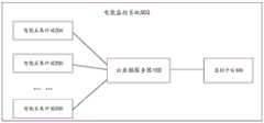
图1为本发明实施例提供的一种电能监控系统的结构示意图;FIG. 1 is a schematic structural diagram of a power monitoring system according to an embodiment of the present invention;
图2为本发明实施例提供的一种电能监控系统中智能采集终端的结构示意图;2 is a schematic structural diagram of an intelligent collection terminal in a power monitoring system provided by an embodiment of the present invention;
图3为本发明实施例提供的一种电能监控系统的应用场景示意图;3 is a schematic diagram of an application scenario of a power monitoring system provided by an embodiment of the present invention;
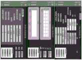
图4为本发明实施例提供的一种计算机上的三相电表数据采集监控界面示意图;4 is a schematic diagram of a three-phase electricity meter data acquisition and monitoring interface on a computer provided by an embodiment of the present invention;
图5为本发明实施例提供的一种计算机上的日用电量报表监控界面示意图;5 is a schematic diagram of a monitoring interface for a daily electricity consumption report on a computer provided by an embodiment of the present invention;
图6为本发明实施例提供的一种移动终端设备的用电监控界面示意图;6 is a schematic diagram of a power consumption monitoring interface of a mobile terminal device according to an embodiment of the present invention;
图7为本发明实施例提供的一种电能监控方法的流程示意图。FIG. 7 is a schematic flowchart of a power monitoring method according to an embodiment of the present invention.
图标:100-云数据服务器;200-智能采集终端;300-监控平台;500-电能监控系统;201-电表;202-控制器;203-人机交互设备。Icons: 100-cloud data server; 200-intelligent acquisition terminal; 300-monitoring platform; 500-power monitoring system; 201-meter; 202-controller; 203-human-computer interaction equipment.
具体实施方式Detailed ways
为使本发明实施例的目的、技术方案和优点更加清楚,下面将结合附图对本发明的技术方案进行清楚、完整地描述,显然,所描述的实施例是本发明一部分实施例,而不是全部的实施例。基于本发明中的实施例,本领域普通技术人员在没有做出创造性劳动前提下所获得的所有其他实施例,都属于本发明保护的范围。In order to make the purposes, technical solutions and advantages of the embodiments of the present invention clearer, the technical solutions of the present invention will be clearly and completely described below with reference to the accompanying drawings. Obviously, the described embodiments are part of the embodiments of the present invention, but not all of them. example. Based on the embodiments of the present invention, all other embodiments obtained by those of ordinary skill in the art without creative efforts shall fall within the protection scope of the present invention.
考虑到现有电力系统中电表数据获取方式还存在获取不及时,获取数据的准确率较低的问题,本发明实施例提供的一种电能监控系统与方法,该技术可以应用于电力监控的各种应用场景中。Considering that in the existing electric power system, the acquisition method of electric meter data still has problems that the acquisition is not timely and the accuracy of the acquired data is low, an electric energy monitoring system and method provided by the embodiments of the present invention can be applied to various power monitoring systems and methods. in various application scenarios.
为便于对本实施例进行理解,首先对本发明实施例所公开的一种电能监控系统进行详细介绍。In order to facilitate the understanding of this embodiment, a power monitoring system disclosed in the embodiment of the present invention is first introduced in detail.
参见图1,所示为本发明实施例提供的一种电能监控系统的结构示意图,由图1可见,该电能监控系统500包括云数据服务器100,以及与所述云数据服务器100通信连接的多个智能采集终端200和监控平台300。Referring to FIG. 1 , a schematic structural diagram of a power monitoring system according to an embodiment of the present invention is shown. As can be seen from FIG. 1 , the power monitoring system 500 includes a
其中,智能采集终端200用于采集目标用户的电表参数和用电数据,并将该电表参数和该用电数据实时发送给该云数据服务器100。云数据服务器100存储接收到的用户的电表参数和用电数据。Wherein, the intelligent collection terminal 200 is used to collect the meter parameters and power consumption data of the target user, and send the meter parameters and the power consumption data to the
这里,云数据服务器100具有简单高效、安全可靠、处理能力可弹性伸缩的特点,其管理方式比物理服务器更简单高效。在实际操作中,该云数据服务器100可以使用海为云服务器。Here, the
另外,上述监控平台300可以是监控站,也可以是通过移动设备例如手机、平板电脑等进行监控。在实际操作中,当需要监控特定用户的历史用电数据是否正常时,监控平台300可以从该云数据服务器100获取该目标用户的历史用电数据,并对该历史用电数据进行分析处理得到处理结果,然后,根据该处理结果监控该目标用户的用电情况。In addition, the above-mentioned
这里,监控平台300对上述历史用电数据的分析处理可以是进行历史数据统计,用以分析用户的用电习惯,查找用电异常等等,并且,对于处理结果,还可以通过表格、图像等方式进行呈现,以便更直观地掌握分析处理结果。在其中一种可能的实施方式中,可以在监控平台300中设置可视化模块,并且,通过该可视化模块对该历史用电数据的处理结果进行可视化呈现。Here, the analysis and processing of the above-mentioned historical power consumption data by the
相比于传统的电表数据获取方式,该系统通过智能采集终端200自动上传用户的电表参数和用电数据,无须人工手抄电表,避免了人为因素的影响,降低了用电数据的出错率,不但可以更加及时地获取用户的电表数据,并且还提高了获取数据的准确率。Compared with the traditional method of acquiring electricity meter data, the system automatically uploads the user's meter parameters and electricity consumption data through the intelligent collection terminal 200, without manual meter reading, avoiding the influence of human factors and reducing the error rate of electricity consumption data. Not only can the user's meter data be obtained in a more timely manner, but also the accuracy of the obtained data can be improved.
如图2所示,为一种电能监控系统中智能采集终端的结构示意图,由图2可见,该监控系统中的智能采集终端200包括电表201、控制器202和人机交互设备203,其中,该控制器202分别与该电表201和该人机交互设备203相连接,并且,该人机交互设备203与该云数据服务器通信连接。As shown in FIG. 2, it is a schematic structural diagram of an intelligent collection terminal in an electric energy monitoring system. As can be seen from FIG. 2, the intelligent collection terminal 200 in the monitoring system includes an electric meter 201, a controller 202 and a human-computer interaction device 203, wherein, The controller 202 is respectively connected with the electricity meter 201 and the human-computer interaction device 203, and the human-computer interaction device 203 is connected in communication with the cloud data server.
在实际运行时,该人机交互设备203用于接收用户的控制指令,并将该控制指令发送给该控制器202,以通过该控制器202对该电表201进行操作。例如,当需要对电表201的参数进行修改时,可以通过该人机交互设备203修改该电表201的对应参数。这样,通过该人机交互设备203,可以更加方便电力工作人员快速地在现场对电表201的性能进行检测和维修。During actual operation, the human-computer interaction device 203 is configured to receive a user's control instruction, and send the control instruction to the controller 202 to operate the electricity meter 201 through the controller 202 . For example, when the parameters of the electric meter 201 need to be modified, the corresponding parameters of the electric meter 201 can be modified through the human-computer interaction device 203 . In this way, through the human-computer interaction device 203, it is more convenient for the electric power worker to quickly test and maintain the performance of the electric meter 201 on site.
在其中一种可能的实施方式中,该智能采集终端200中的控制器202可以是可编程逻辑控制器,并且,该可编程逻辑控制器通过RS232接口与该人机交互设备203通信连接。这里,可编程逻辑控制器(Programmable Logic Controller,PLC)是一种具有微处理器的用于自动化控制的数字运算控制器,它可以将控制指令随时载入内存进行储存与执行。通常情况下,可编程控制器由CPU、指令及数据内存、输入/输出接口、电源和数字模拟转换等功能单元组成。In one possible implementation, the controller 202 in the intelligent collection terminal 200 may be a programmable logic controller, and the programmable logic controller communicates with the human-computer interaction device 203 through an RS232 interface. Here, a programmable logic controller (Programmable Logic Controller, PLC) is a digital operation controller with a microprocessor for automatic control, which can load control instructions into a memory at any time for storage and execution. Normally, a programmable controller consists of functional units such as CPU, instruction and data memory, input/output interface, power supply, and digital-to-analog conversion.
在至少一种可能的实施方式中,上述智能采集终端200中的人机交互设备203可以是海为C7触摸屏人机交互设备,该设备具有7寸触摸屏,通过可编程逻辑控制器与电表201进行连接后,可以获取电表201的实时数据,并可以展示在显示界面上,具有很好的操作性。In at least one possible implementation, the human-computer interaction device 203 in the above-mentioned intelligent collection terminal 200 may be a Haiwell C7 touch-screen human-computer interaction device, which has a 7-inch touch screen, and communicates with the electricity meter 201 through a programmable logic controller. After the connection, the real-time data of the electric meter 201 can be obtained and displayed on the display interface, which has good operability.
在实际操作中,为了方便智能采集终端200接入云数据服务器,轻松实现数据采集上报,以及对接ERP(Enterprise Resource Planning,企业应急计划)和MES(Manufacturing Execution System,制造执行系统)等系统,还在智能采集终端200中的人机交互设备203中设置有消息队列遥测传输模块(Message Queuing TelemetryTransport,MQTT),该消息队列遥测传输模块用于开启消息队列遥测传输的代理功能,以进行无线传输的自组网。In actual operation, in order to facilitate the intelligent collection terminal 200 to access the cloud data server, easily realize data collection and reporting, and connect with ERP (Enterprise Resource Planning, enterprise emergency plan) and MES (Manufacturing Execution System, manufacturing execution system) and other systems, also The human-computer interaction device 203 in the intelligent collection terminal 200 is provided with a message queue telemetry transmission module (Message Queuing TelemetryTransport, MQTT), and the message queue telemetry transmission module is used to enable the proxy function of the message queue telemetry transmission to perform wireless transmission. Self-organized network.
在另一种可能的实施方式中,如果上述监控平台监控到用户的历史用电数据的处理结果出现异常,该监控平台还可以向预设终端设备发送告警信息,其中,该终端设备可以是手机、计算机或平板电脑等等。并且,通过在智能采集终端200中设置定位模块,该用于获取该智能采集终端200的位置信息,使得在监控平台也可以获取各个电表201的分布,掌握不同区域的用电情况。当发现用电异常时,也可以结合电表201的位置,方便电力人员及时地到现场处理电力异常,减少因电力故障而造成的损失。In another possible implementation, if the above monitoring platform monitors that the processing result of the user's historical power consumption data is abnormal, the monitoring platform may also send alarm information to a preset terminal device, where the terminal device may be a mobile phone , computer or tablet, etc. In addition, by setting the positioning module in the intelligent collection terminal 200 for obtaining the location information of the intelligent collection terminal 200, the monitoring platform can also obtain the distribution of each electricity meter 201 and grasp the electricity consumption in different areas. When abnormal power consumption is found, the location of the electricity meter 201 can also be combined to facilitate the electric power personnel to go to the site to deal with the abnormal power in time and reduce the loss caused by the power failure.
为了更清楚理解上述电能监控系统,这里还介绍了一个实际应用场景,参见图3,所示为一种电能监控系统的应用场景示意图,在图3示出的实施方式中,该电能监控系统包括云数据服务器、多个智能采集终端和监控平台,其中,该云数据服务器分别与上述智能采集终端和监控平台通信连接。并且,该智能采集终端包括电表、可编程逻辑控制器和人机交互设备。In order to understand the above power monitoring system more clearly, a practical application scenario is also introduced here. Referring to FIG. 3, a schematic diagram of an application scenario of a power monitoring system is shown. In the embodiment shown in FIG. 3, the power monitoring system includes: A cloud data server, a plurality of intelligent collection terminals and a monitoring platform, wherein the cloud data server is respectively connected to the above-mentioned intelligent collection terminals and monitoring platform in communication. Moreover, the intelligent acquisition terminal includes an electric meter, a programmable logic controller and a human-computer interaction device.
在图3中,该人机交互设备为海为物联云人机交互设备(Human MachineInterface,HMI),并且,该人机交互设备通过GBOX路由器与该云数据服务器通信连接。这里,GBOX路由器为4G工业路由器,在实际操作中,通过网线将GBOX路由器的LAN口和海为物联云人机交互设备的LAN口进行连接,从而实现该人机交互设备与云数据服务器之间的数据通信。其中,该海为物联云人机交互设备具有7寸显示屏。In FIG. 3 , the human-computer interaction device is Haiwell IoT cloud human-computer interaction device (Human Machine Interface, HMI), and the human-computer interaction device communicates and connects with the cloud data server through a GBOX router. Here, the GBOX router is a 4G industrial router. In actual operation, the LAN port of the GBOX router is connected to the LAN port of the Haiwell IoT cloud human-computer interaction device through a network cable, so as to realize the connection between the human-computer interaction device and the cloud data server. data communication between. Among them, the Haiwell IoT cloud human-computer interaction device has a 7-inch display screen.
在图3示出的实施方式中,云数据服务器为海为云服务器,其支持通过海为数据互联工具,将实时数据、历史数据存入MySQL、SQL Server等数据库,并支持数据下发。同时,海为云服务器还可以配合海为数据可视化系统,轻松生成各种数据报表,实现数据分析和数据大屏呈现,为管理决策提供各种数据的支持。In the embodiment shown in FIG. 3 , the cloud data server is a Haiwell cloud server, which supports the storage of real-time data and historical data in databases such as MySQL and SQL Server through the Haiwell data interconnection tool, and supports data delivery. At the same time, Haiwell cloud server can also cooperate with Haiwell data visualization system to easily generate various data reports, realize data analysis and data display on a large screen, and provide various data support for management decision-making.
这里,基于图3示出的电能监控系统,参见图4、图5和图6,均为在监控平台的监控界面示意图,其中,图4为一种计算机上的三相电表数据采集监控界面示意图,图5为一种计算机上的日用电量报表监控界面示意图,图6为一种移动终端设备的用电监控界面示意图,可见,通过该电能监控系统,可以即时获取各个智能采集终端的用电情况,非常方便快捷,并且通过图表的形式展现,可以对采集终端的实时状态一目了然。Here, based on the power monitoring system shown in Fig. 3, see Fig. 4, Fig. 5 and Fig. 6, which are schematic diagrams of the monitoring interface on the monitoring platform, wherein, Fig. 4 is a schematic diagram of a three-phase electricity meter data acquisition monitoring interface on a computer , FIG. 5 is a schematic diagram of a daily electricity consumption report monitoring interface on a computer, and FIG. 6 is a schematic diagram of a power consumption monitoring interface of a mobile terminal device. It can be seen that through the power monitoring system, the power consumption of each intelligent collection terminal can be obtained in real time. The power status is very convenient and fast, and it is displayed in the form of a chart, so that the real-time status of the acquisition terminal can be seen at a glance.
此外,通过海为云组态软件,也可以灵活调用各地智能采集终端的设备变量数据,实现对异地设备的集中控制。并且,通过该监控系统,还可以在手机上实现远程查看所有智能采集终端设备的地理位置,也可以在大屏幕上全屏展示所有设备分布的地图,既直观又便利;通过搭配智能采集终端的实时报警跳动功能,可快速发现报警设备所在位置。In addition, through Haiwell cloud configuration software, it is also possible to flexibly call the device variable data of the intelligent collection terminals in various places, so as to realize the centralized control of the remote devices. In addition, through the monitoring system, it is also possible to remotely view the geographical location of all intelligent collection terminal equipment on the mobile phone, and to display the map of all equipment distribution in full screen on the large screen, which is both intuitive and convenient; The alarm beating function can quickly find the location of the alarm equipment.
本发明实施例提供的一种电能监控系统,该系统包括云数据服务器、多个智能采集终端和监控平台;该云数据服务器分别与上述智能采集终端和监控平台通信连接;该智能采集终端用于采集目标用户的电表参数和用电数据,并将该电表参数和该用电数据实时发送给该云数据服务器;该云数据服务器用于存储该电表参数和该用电数据;该监控平台用于从该云数据服务器获取该目标用户的历史用电数据,并对该历史用电数据进行分析处理得到处理结果,以根据该处理结果监控该目标用户的用电情况。该系统通过智能采集终端自动上传用户的电表参数和用电数据,无须人工手抄电表,避免了人为因素的影响,降低了用电数据的出错率,不但可以更加及时地获取用户的电表数据,并且还提高了获取数据的准确率。此外,该系统还通过可视化模块,可以将用户历史用电数据的处理结果进行可视化呈现,从而更加直观方便地掌握用电情况;并且,通过在智能采集终端设置定位模块,并获取采集终端的位置信息,可以直观掌握各处采集终端的分布情况,给用电调度提供指导;再者,当监控发现用户用电出现异常时,还可以主动向终端设备进行报警,以及时进行处理,从而可有效避免用电事故的发生。An electric energy monitoring system provided by an embodiment of the present invention includes a cloud data server, a plurality of intelligent collection terminals, and a monitoring platform; the cloud data server is respectively connected to the above-mentioned intelligent collection terminal and monitoring platform in communication; the intelligent collection terminal is used for Collect the meter parameters and power consumption data of the target user, and send the meter parameters and the power consumption data to the cloud data server in real time; the cloud data server is used to store the meter parameters and the power consumption data; the monitoring platform is used for Obtain the historical electricity consumption data of the target user from the cloud data server, and analyze and process the historical electricity consumption data to obtain a processing result, so as to monitor the electricity consumption condition of the target user according to the processing result. The system automatically uploads the user's meter parameters and electricity consumption data through the intelligent collection terminal, without manual meter reading, avoiding the influence of human factors, reducing the error rate of electricity consumption data, and not only obtaining the user's electricity meter data in a more timely manner, And also improve the accuracy of data acquisition. In addition, the system can visualize the processing results of the user's historical electricity consumption data through the visualization module, so as to grasp the electricity consumption situation more intuitively and conveniently; and, by setting a positioning module on the intelligent collection terminal, the location of the collection terminal can be obtained. In addition, when the monitoring finds that the user's electricity consumption is abnormal, it can also actively send an alarm to the terminal equipment and deal with it in time, so as to effectively Avoid electricity accidents.
对应于图1中所示的电能监控系统,本发明实施例还提供了一种电能监控方法,该方法应用于监控平台,该监控平台与预设的云数据服务器通信连接;该云数据服务器与多个智能采集终端通信连接,用于存储该智能采集终端采集并发送的目标用户的电表参数和用电数据。Corresponding to the power monitoring system shown in FIG. 1 , an embodiment of the present invention further provides a power monitoring method, which is applied to a monitoring platform, and the monitoring platform is communicatively connected to a preset cloud data server; the cloud data server is connected to a monitoring platform. A plurality of intelligent collection terminals are connected for communication, and are used for storing the meter parameters and electricity consumption data of target users collected and sent by the intelligent collection terminals.
参见图7,所示为本发明实施例提供的一种电能监控方法的流程示意图,由图7可见,该方法包括以下步骤:Referring to FIG. 7 , it is a schematic flowchart of a power monitoring method provided by an embodiment of the present invention. As can be seen from FIG. 7 , the method includes the following steps:
步骤S702:从云数据服务器获取目标用户的历史用电数据;Step S702: obtaining historical electricity consumption data of the target user from the cloud data server;
步骤S704:对该历史用电数据进行分析处理得到处理结果,以根据该处理结果监控该目标用户的用电情况。Step S704: Analyzing and processing the historical power consumption data to obtain a processing result, so as to monitor the electricity consumption of the target user according to the processing result.
本发明实施例提供的一种电能监控方法,通过智能采集终端自动上传用户的电表参数和用电数据,无须人工手抄电表,避免了人为因素的影响,降低了用电数据的出错率,不但可以更加及时地获取用户的电表数据,并且还提高了获取数据的准确率。The power monitoring method provided by the embodiment of the present invention automatically uploads the user's power meter parameters and power consumption data through an intelligent collection terminal, and does not need to manually read the power meter, avoids the influence of human factors, and reduces the error rate of power consumption data. The user's meter data can be acquired in a more timely manner, and the accuracy of acquiring the data is also improved.
本发明实施例所提供的电能监控方法和电能监控系统的计算机程序产品,包括存储了程序代码的计算机可读存储介质,所述程序代码包括的指令可用于执行前面方法实施例中所述的电能监控方法,具体实现可参见方法实施例,在此不再赘述。The computer program product of the power monitoring method and power monitoring system provided by the embodiments of the present invention includes a computer-readable storage medium storing program codes, and the instructions included in the program codes can be used to execute the power described in the foregoing method embodiments. For the monitoring method, the specific implementation can refer to the method embodiment, which is not repeated here.
所述功能如果以软件功能单元的形式实现并作为独立的产品销售或使用时,可以存储在一个处理器可执行的非易失的计算机可读取存储介质中。基于这样的理解,本发明的技术方案本质上或者说对现有技术做出贡献的部分或者该技术方案的部分可以以软件产品的形式体现出来,该计算机软件产品存储在一个存储介质中,包括若干指令用以使得一台计算机设备(可以是个人计算机,服务器,或者网络设备等)执行本发明各个实施例所述方法的全部或部分步骤。而前述的存储介质包括:U盘、移动硬盘、只读存储器(ROM,Read-Only Memory)、随机存取存储器(RAM,Random Access Memory)、磁碟或者光盘等各种可以存储程序代码的介质。The functions, if implemented in the form of software functional units and sold or used as stand-alone products, may be stored in a processor-executable non-volatile computer-readable storage medium. Based on this understanding, the technical solution of the present invention can be embodied in the form of a software product in essence, or the part that contributes to the prior art or the part of the technical solution. The computer software product is stored in a storage medium, including Several instructions are used to cause a computer device (which may be a personal computer, a server, or a network device, etc.) to execute all or part of the steps of the methods described in the various embodiments of the present invention. The aforementioned storage medium includes: U disk, mobile hard disk, Read-Only Memory (ROM, Read-Only Memory), Random Access Memory (RAM, Random Access Memory), magnetic disk or optical disk and other media that can store program codes .
另外,在本发明实施例的描述中,除非另有明确的规定和限定,术语“安装”、“相连”、“连接”应做广义理解,例如,可以是固定连接,也可以是可拆卸连接,或一体地连接;可以是机械连接,也可以是电连接;可以是直接相连,也可以通过中间媒介间接相连,可以是两个元件内部的连通。对于本领域的普通技术人员而言,可以具体情况理解上述术语在本发明中的具体含义。In addition, in the description of the embodiments of the present invention, unless otherwise expressly specified and limited, the terms "installed", "connected" and "connected" should be understood in a broad sense, for example, it may be a fixed connection or a detachable connection , or integrally connected; it can be a mechanical connection or an electrical connection; it can be a direct connection, or an indirect connection through an intermediate medium, or the internal communication between the two components. For those of ordinary skill in the art, the specific meanings of the above terms in the present invention can be understood in specific situations.
在本发明的描述中,需要说明的是,术语“中心”、“上”、“下”、“左”、“右”、“竖直”、“水平”、“内”、“外”等指示的方位或位置关系为基于附图所示的方位或位置关系,仅是为了便于描述本发明和简化描述,而不是指示或暗示所指的装置或元件必须具有特定的方位、以特定的方位构造和操作,因此不能理解为对本发明的限制。此外,术语“第一”、“第二”、“第三”仅用于描述目的,而不能理解为指示或暗示相对重要性。In the description of the present invention, it should be noted that the terms "center", "upper", "lower", "left", "right", "vertical", "horizontal", "inner", "outer", etc. The indicated orientation or positional relationship is based on the orientation or positional relationship shown in the accompanying drawings, which is only for the convenience of describing the present invention and simplifying the description, rather than indicating or implying that the indicated device or element must have a specific orientation or a specific orientation. construction and operation, and therefore should not be construed as limiting the invention. Furthermore, the terms "first", "second", and "third" are used for descriptive purposes only and should not be construed to indicate or imply relative importance.
最后应说明的是:以上所述实施例,仅为本发明的具体实施方式,用以说明本发明的技术方案,而非对其限制,本发明的保护范围并不局限于此,尽管参照前述实施例对本发明进行了详细的说明,本领域的普通技术人员应当理解:任何熟悉本技术领域的技术人员在本发明揭露的技术范围内,其依然可以对前述实施例所记载的技术方案进行修改或可轻易想到变化,或者对其中部分技术特征进行等同替换;而这些修改、变化或者替换,并不使相应技术方案的本质脱离本发明实施例技术方案的精神和范围,都应涵盖在本发明的保护范围之内。因此,本发明的保护范围应以所述权利要求的保护范围为准。Finally, it should be noted that the above-mentioned embodiments are only specific implementations of the present invention, and are used to illustrate the technical solutions of the present invention, but not to limit them. The protection scope of the present invention is not limited thereto, although referring to the foregoing The embodiment has been described in detail the present invention, those of ordinary skill in the art should understand: any person skilled in the art who is familiar with the technical field within the technical scope disclosed by the present invention can still modify the technical solutions described in the foregoing embodiments. Or can easily think of changes, or equivalently replace some of the technical features; and these modifications, changes or replacements do not make the essence of the corresponding technical solutions deviate from the spirit and scope of the technical solutions of the embodiments of the present invention, and should be covered in the present invention. within the scope of protection. Therefore, the protection scope of the present invention should be based on the protection scope of the claims.
Claims (10)
Translated fromChinesePriority Applications (1)
| Application Number | Priority Date | Filing Date | Title |
|---|---|---|---|
| CN202010401066.7ACN111586188A (en) | 2020-05-12 | 2020-05-12 | Electric energy monitoring system and method |
Applications Claiming Priority (1)
| Application Number | Priority Date | Filing Date | Title |
|---|---|---|---|
| CN202010401066.7ACN111586188A (en) | 2020-05-12 | 2020-05-12 | Electric energy monitoring system and method |
Publications (1)
| Publication Number | Publication Date |
|---|---|
| CN111586188Atrue CN111586188A (en) | 2020-08-25 |
Family
ID=72124887
Family Applications (1)
| Application Number | Title | Priority Date | Filing Date |
|---|---|---|---|
| CN202010401066.7APendingCN111586188A (en) | 2020-05-12 | 2020-05-12 | Electric energy monitoring system and method |
Country Status (1)
| Country | Link |
|---|---|
| CN (1) | CN111586188A (en) |
Cited By (6)
| Publication number | Priority date | Publication date | Assignee | Title |
|---|---|---|---|---|
| CN113341366A (en)* | 2021-05-26 | 2021-09-03 | 广东电网有限责任公司广州供电局 | Method, device and storage medium for monitoring state of user electric meter |
| CN113596625A (en)* | 2021-08-06 | 2021-11-02 | 清华四川能源互联网研究院 | Electric energy meter data transmission method and device of message queue telemetry transmission protocol |
| CN114487646A (en)* | 2021-12-22 | 2022-05-13 | 江苏金晓电子信息股份有限公司 | Urban rail transit electric energy management system |
| CN115175023A (en)* | 2022-09-07 | 2022-10-11 | 安徽南瑞中天电力电子有限公司 | Photovoltaic inverter-based method, system and device for reading meter of internet of things |
| CN115224802A (en)* | 2022-08-10 | 2022-10-21 | 国网河北省电力有限公司信息通信分公司 | Information communication system based on cloud server |
| CN118263978A (en)* | 2024-03-25 | 2024-06-28 | 广东电网有限责任公司中山供电局 | Method and device for intelligently collecting evidence objects |
Citations (9)
| Publication number | Priority date | Publication date | Assignee | Title |
|---|---|---|---|---|
| CN101951027A (en)* | 2010-09-01 | 2011-01-19 | 中国电力科学研究院 | Uniform data acquisition and monitoring system of low-medium voltage power distribution network |
| CN204376538U (en)* | 2015-02-03 | 2015-06-03 | 张海武 | A kind of intelligent distribution transforming runs real-time monitoring system |
| CN106251034A (en)* | 2016-07-08 | 2016-12-21 | 大连大学 | Wisdom energy saving electric meter monitoring system based on cloud computing technology |
| CN106443168A (en)* | 2016-09-27 | 2017-02-22 | 国网山东省电力公司济南供电公司 | Remote acquisition meter reading data analysis system |
| CN107093069A (en)* | 2017-06-20 | 2017-08-25 | 上海闻泰电子科技有限公司 | Intelligent electric meter data handling system and method |
| CN107328992A (en)* | 2017-09-01 | 2017-11-07 | 常州工程职业技术学院 | A kind of power information collection monitoring system based on cloud |
| CN107390624A (en)* | 2017-08-24 | 2017-11-24 | 广东雅达电子股份有限公司 | A kind of electric real training intelligence system and its management method based on cloud platform |
| CN110009525A (en)* | 2019-04-02 | 2019-07-12 | 国网新疆电力有限公司电力科学研究院 | Electricity consumption information collection system and using method |
| CN110247476A (en)* | 2019-06-18 | 2019-09-17 | 佛山科学技术学院 | A kind of industry park electricity consumption intelligent monitor system |
- 2020
- 2020-05-12CNCN202010401066.7Apatent/CN111586188A/enactivePending
Patent Citations (9)
| Publication number | Priority date | Publication date | Assignee | Title |
|---|---|---|---|---|
| CN101951027A (en)* | 2010-09-01 | 2011-01-19 | 中国电力科学研究院 | Uniform data acquisition and monitoring system of low-medium voltage power distribution network |
| CN204376538U (en)* | 2015-02-03 | 2015-06-03 | 张海武 | A kind of intelligent distribution transforming runs real-time monitoring system |
| CN106251034A (en)* | 2016-07-08 | 2016-12-21 | 大连大学 | Wisdom energy saving electric meter monitoring system based on cloud computing technology |
| CN106443168A (en)* | 2016-09-27 | 2017-02-22 | 国网山东省电力公司济南供电公司 | Remote acquisition meter reading data analysis system |
| CN107093069A (en)* | 2017-06-20 | 2017-08-25 | 上海闻泰电子科技有限公司 | Intelligent electric meter data handling system and method |
| CN107390624A (en)* | 2017-08-24 | 2017-11-24 | 广东雅达电子股份有限公司 | A kind of electric real training intelligence system and its management method based on cloud platform |
| CN107328992A (en)* | 2017-09-01 | 2017-11-07 | 常州工程职业技术学院 | A kind of power information collection monitoring system based on cloud |
| CN110009525A (en)* | 2019-04-02 | 2019-07-12 | 国网新疆电力有限公司电力科学研究院 | Electricity consumption information collection system and using method |
| CN110247476A (en)* | 2019-06-18 | 2019-09-17 | 佛山科学技术学院 | A kind of industry park electricity consumption intelligent monitor system |
Cited By (8)
| Publication number | Priority date | Publication date | Assignee | Title |
|---|---|---|---|---|
| CN113341366A (en)* | 2021-05-26 | 2021-09-03 | 广东电网有限责任公司广州供电局 | Method, device and storage medium for monitoring state of user electric meter |
| CN113596625A (en)* | 2021-08-06 | 2021-11-02 | 清华四川能源互联网研究院 | Electric energy meter data transmission method and device of message queue telemetry transmission protocol |
| CN113596625B (en)* | 2021-08-06 | 2024-08-20 | 清华四川能源互联网研究院 | Electric energy meter data transmission method and device of message queue telemetry transmission protocol |
| CN114487646A (en)* | 2021-12-22 | 2022-05-13 | 江苏金晓电子信息股份有限公司 | Urban rail transit electric energy management system |
| CN115224802A (en)* | 2022-08-10 | 2022-10-21 | 国网河北省电力有限公司信息通信分公司 | Information communication system based on cloud server |
| CN115175023A (en)* | 2022-09-07 | 2022-10-11 | 安徽南瑞中天电力电子有限公司 | Photovoltaic inverter-based method, system and device for reading meter of internet of things |
| CN115175023B (en)* | 2022-09-07 | 2022-11-08 | 安徽南瑞中天电力电子有限公司 | Photovoltaic inverter-based method, system and device for reading meter of internet of things |
| CN118263978A (en)* | 2024-03-25 | 2024-06-28 | 广东电网有限责任公司中山供电局 | Method and device for intelligently collecting evidence objects |
Similar Documents
| Publication | Publication Date | Title |
|---|---|---|
| CN111586188A (en) | Electric energy monitoring system and method | |
| CN112069247A (en) | Power system operation data visualization system and method based on digital twin technology | |
| CN112666885A (en) | Environmental protection equipment monitoring management platform based on industrial internet | |
| CN111190375B (en) | Intelligent monitoring system and monitoring method for hydropower station equipment | |
| CN113179291A (en) | Safe power utilization system of Internet of things | |
| CN111897254A (en) | An intelligent valve performance analysis system and method based on the Internet of Things | |
| CN108733531B (en) | GPU performance monitoring system based on cloud computing | |
| CN103178617B (en) | Power grid operation state monitoring and analyzing system and method for power system | |
| CN110995859A (en) | Intelligent transformer substation supporting platform system based on ubiquitous Internet of things | |
| CN111541576A (en) | Zigbee network-based equipment visualization method and system | |
| CN113315222A (en) | Intelligent substation automation equipment operation and maintenance management and control system suitable for electric power system | |
| CN112578756A (en) | Monitoring system and monitoring method for abnormal data of industrial equipment | |
| CN109409732A (en) | A kind of energy consumption management system and management method | |
| CN104218679A (en) | Remote automatic transformer substation polling method based on remote viewing system | |
| CN118735118A (en) | Power supply service construction system and method in different scenarios based on digital twin | |
| CN109581115B (en) | Power distribution network low-voltage diagnosis system and diagnosis method | |
| CN109714191B (en) | Portable fault recording and message analysis method for substation based on mobile internet | |
| CN117421121A (en) | Machine room load early warning method and device, storage medium and electronic equipment | |
| CN118306250A (en) | Intelligent edge monitoring device and method for electric automobile charging pile | |
| CN115459434A (en) | Intelligent electricity consumption monitoring method and system for industrial enterprise | |
| CN115511296A (en) | Park energy efficiency integrated management method, system, equipment and storage medium | |
| CN104134168A (en) | a data management system | |
| CN112737124B (en) | Method and device for constructing power equipment monitoring terminal | |
| CN203151231U (en) | Monitoring and analysis system for power grid running state of electrical power system | |
| CN201837466U (en) | System for monitoring, managing and analyzing temperature system of high-tension cable |
Legal Events
| Date | Code | Title | Description |
|---|---|---|---|
| PB01 | Publication | ||
| PB01 | Publication | ||
| SE01 | Entry into force of request for substantive examination | ||
| SE01 | Entry into force of request for substantive examination | ||
| RJ01 | Rejection of invention patent application after publication | Application publication date:20200825 | |
| RJ01 | Rejection of invention patent application after publication |