CN111584336B - Air intake device, gas reaction system and cleaning method thereof - Google Patents
Air intake device, gas reaction system and cleaning method thereofDownload PDFInfo
- Publication number
- CN111584336B CN111584336BCN201910120050.6ACN201910120050ACN111584336BCN 111584336 BCN111584336 BCN 111584336BCN 201910120050 ACN201910120050 ACN 201910120050ACN 111584336 BCN111584336 BCN 111584336B
- Authority
- CN
- China
- Prior art keywords
- gas
- air intake
- channel
- unit
- flow channel
- Prior art date
- Legal status (The legal status is an assumption and is not a legal conclusion. Google has not performed a legal analysis and makes no representation as to the accuracy of the status listed.)
- Active
Links
- 238000004140cleaningMethods0.000titleclaimsabstractdescription124
- 238000000034methodMethods0.000titleclaimsabstractdescription53
- 239000006185dispersionSubstances0.000claimsabstractdescription110
- 239000007789gasSubstances0.000claimsdescription381
- 238000010438heat treatmentMethods0.000claimsdescription27
- 238000009826distributionMethods0.000claimsdescription20
- 239000012495reaction gasSubstances0.000claimsdescription17
- 238000011109contaminationMethods0.000claimsdescription13
- 238000011156evaluationMethods0.000claimsdescription11
- 238000012854evaluation processMethods0.000claimsdescription7
- 230000002093peripheral effectEffects0.000claimsdescription3
- 230000035515penetrationEffects0.000claimsdescription2
- 238000010926purgeMethods0.000claimsdescription2
- 230000001105regulatory effectEffects0.000description13
- 238000001816coolingMethods0.000description7
- 239000003344environmental pollutantSubstances0.000description7
- 231100000719pollutantToxicity0.000description7
- 230000000694effectsEffects0.000description6
- 239000000758substrateSubstances0.000description5
- 239000004065semiconductorSubstances0.000description4
- 239000010409thin filmSubstances0.000description4
- 238000004891communicationMethods0.000description3
- 230000008021depositionEffects0.000description3
- 239000012809cooling fluidSubstances0.000description2
- 238000005520cutting processMethods0.000description2
- 230000007547defectEffects0.000description2
- 230000001154acute effectEffects0.000description1
- 230000015572biosynthetic processEffects0.000description1
- 230000003749cleanlinessEffects0.000description1
- 239000000356contaminantSubstances0.000description1
- 230000007797corrosionEffects0.000description1
- 238000005260corrosionMethods0.000description1
- 230000007423decreaseEffects0.000description1
- 230000003247decreasing effectEffects0.000description1
- 238000013461designMethods0.000description1
- 238000010586diagramMethods0.000description1
- 238000005530etchingMethods0.000description1
- 230000002452interceptive effectEffects0.000description1
- QKCGXXHCELUCKW-UHFFFAOYSA-Nn-[4-[4-(dinaphthalen-2-ylamino)phenyl]phenyl]-n-naphthalen-2-ylnaphthalen-2-amineChemical compoundC1=CC=CC2=CC(N(C=3C=CC(=CC=3)C=3C=CC(=CC=3)N(C=3C=C4C=CC=CC4=CC=3)C=3C=C4C=CC=CC4=CC=3)C3=CC4=CC=CC=C4C=C3)=CC=C21QKCGXXHCELUCKW-UHFFFAOYSA-N0.000description1
- 238000012545processingMethods0.000description1
- 238000004904shorteningMethods0.000description1
- 238000004347surface barrierMethods0.000description1
Images


Classifications
- H—ELECTRICITY
- H01—ELECTRIC ELEMENTS
- H01J—ELECTRIC DISCHARGE TUBES OR DISCHARGE LAMPS
- H01J37/00—Discharge tubes with provision for introducing objects or material to be exposed to the discharge, e.g. for the purpose of examination or processing thereof
- H01J37/32—Gas-filled discharge tubes
- H01J37/32431—Constructional details of the reactor
- H01J37/3244—Gas supply means
- H01J37/32449—Gas control, e.g. control of the gas flow
- H—ELECTRICITY
- H01—ELECTRIC ELEMENTS
- H01J—ELECTRIC DISCHARGE TUBES OR DISCHARGE LAMPS
- H01J37/00—Discharge tubes with provision for introducing objects or material to be exposed to the discharge, e.g. for the purpose of examination or processing thereof
- H01J37/32—Gas-filled discharge tubes
- H01J37/32431—Constructional details of the reactor
- H01J37/32798—Further details of plasma apparatus not provided for in groups H01J37/3244 - H01J37/32788; special provisions for cleaning or maintenance of the apparatus
- H01J37/32853—Hygiene
- H01J37/32862—In situ cleaning of vessels and/or internal parts
- H—ELECTRICITY
- H01—ELECTRIC ELEMENTS
- H01J—ELECTRIC DISCHARGE TUBES OR DISCHARGE LAMPS
- H01J2237/00—Discharge tubes exposing object to beam, e.g. for analysis treatment, etching, imaging
- H01J2237/32—Processing objects by plasma generation
- H01J2237/33—Processing objects by plasma generation characterised by the type of processing
- H01J2237/332—Coating
Landscapes
- Physics & Mathematics (AREA)
- Engineering & Computer Science (AREA)
- Plasma & Fusion (AREA)
- Chemical & Material Sciences (AREA)
- Analytical Chemistry (AREA)
- Health & Medical Sciences (AREA)
- Epidemiology (AREA)
- Public Health (AREA)
Abstract
Description
Translated fromChinese技术领域technical field
本揭露是有关一种进气装置,且特别是提供一种具有调节元件的进气装置、气体分应系统与此气体反应系统的清洗方法。The disclosure relates to an air intake device, and in particular provides an air intake device with an adjustment element, a gas distribution system and a cleaning method for the gas reaction system.
背景技术Background technique
为了呈现出不同的半导体特性,可通过导入气体,以于半导体基材上堆叠不同薄膜层,以满足应用需求。薄膜层的形成一般可利用气体与基材表面间的反应来达成。首先,将半导体基材放置于加热元件上,再导入反应气体至气体反应系统中,并依据需求设定加热元件的温度与系统压力,以使气体分子与半导体基材表面产生反应,以沉积薄膜层于基材表面。In order to exhibit different semiconductor properties, different thin film layers can be stacked on the semiconductor substrate by introducing gas to meet application requirements. The formation of thin film layers can generally be achieved by utilizing the reaction between the gas and the surface of the substrate. First, place the semiconductor substrate on the heating element, then introduce the reaction gas into the gas reaction system, and set the temperature of the heating element and system pressure according to the requirements, so that the gas molecules react with the surface of the semiconductor substrate to deposit a thin film layer on the substrate surface.
发明内容Contents of the invention
根据本揭露的一态样,提出一种进气装置。此进气装置包含进气单元。进气单元包含本体、第一流道、第二流道与多个调节元件。本体包含顶表面、底表面与侧面,且侧面连接顶表面与底表面。顶表面具有顶面开孔、底表面具有多个底面开孔,且侧面具有多个第一侧面开孔与第二侧面开孔。第一流道贯穿本体。第二流道包含多个第一子流道与多个第二子流道。这些第一子流道连通顶面开孔,且以一对一的方式连通第一侧面开孔与底面开孔两者。这些第二子流道连通顶面开孔,且以一对一的方式连通第二侧面开孔。调节元件分别具有多个通道,且这些调节元件是以一对一的方式设置于第一子流道与第二子流道中。According to an aspect of the present disclosure, an air intake device is provided. The air intake device includes an air intake unit. The air intake unit includes a body, a first flow channel, a second flow channel and a plurality of adjustment elements. The body includes a top surface, a bottom surface and a side surface, and the side surface connects the top surface and the bottom surface. The top surface has a top opening, the bottom surface has a plurality of bottom openings, and the side has a plurality of first side openings and second side openings. The first flow channel runs through the body. The second channel includes a plurality of first sub-channels and a plurality of second sub-channels. The first sub-channels communicate with the openings on the top surface, and communicate with the openings on the first side surface and the openings on the bottom surface in a one-to-one manner. The second sub-channels communicate with the top openings and communicate with the second side openings in a one-to-one manner. The adjustment elements respectively have a plurality of channels, and these adjustment elements are arranged in the first sub-channel and the second sub-channel in a one-to-one manner.
根据本揭露的另一态样,提出一种气体反应系统。此气体反应系统包含腔体、进气装置、反应气体供应装置、清洗气体供应装置与加热装置。此腔体具有一顶开口,且进气装置设置于顶开口,以形成腔体空间于腔体中。反应气体供应装置连通进气装置的进气单元的第一流道,且清洗气体供应装置连通进气单元的第二流道。加热装置是设置于腔体空间中,且此加热装置是位于进气装置下。According to another aspect of the present disclosure, a gas reaction system is provided. The gas reaction system includes a cavity, an air inlet device, a reaction gas supply device, a cleaning gas supply device and a heating device. The cavity has a top opening, and the air inlet device is arranged on the top opening to form a cavity space in the cavity. The reactive gas supply device communicates with the first channel of the air intake unit of the air intake device, and the cleaning gas supply device communicates with the second channel of the air intake unit. The heating device is arranged in the cavity space, and the heating device is located under the air inlet device.
根据本揭露的又一态样,提出一种气体反应系统的清洗方法。此清洗方法是先提供气体反应系统,并进行评估制程,以比较气体分散单元的多个区域的脏污程度,而获得气体分散单元的脏污评估结果。气体反应系统包含腔体、进气装置与加热装置。腔体具有顶开口,且进气装置设置于顶开口,以形成腔体空间于腔体中。进气装置包含进气单元、气体分散单元与气体分散板。进气单元包含第一流道与第二流道。第一流道贯穿进气单元的顶表面与底表面,且第二流道连通进气单元的顶表面的顶面开孔、底表面的多个底面通孔与侧面的多个侧面通孔。气体分散单元具有凹陷部,且进气单元容置于凹陷部中。气体分散单元的底板设有多个气体贯穿孔。气体分散板是固设于进气单元的底表面,且位于进气单元与气体分散单元之间。气体分散板包含多个气体通道,且这些气体通道分别以一对一的方式连通底面开孔。加热装置是设置于腔体空间中,且位于进气装置下。然后,根据脏污评估结果,进行调整制程。调整制程是调整第二流道的多个调整位置的每一者的流道截面积。于进行调整制程后,供给清洗气体至第二流道中,以进行清洗制程。According to another aspect of the present disclosure, a method for cleaning a gas reaction system is provided. In this cleaning method, a gas reaction system is firstly provided, and an evaluation process is performed to compare the degree of contamination of multiple regions of the gas dispersion unit, so as to obtain the contamination evaluation result of the gas dispersion unit. The gas reaction system includes a cavity, an air inlet device and a heating device. The cavity has a top opening, and the air inlet device is arranged on the top opening to form a cavity space in the cavity. The air intake device includes an air intake unit, a gas dispersion unit and a gas dispersion plate. The intake unit includes a first flow channel and a second flow channel. The first flow channel runs through the top surface and the bottom surface of the air intake unit, and the second flow channel communicates with the top opening on the top surface of the air intake unit, the bottom through holes on the bottom surface and the side through holes on the side. The gas dispersing unit has a recessed portion, and the air intake unit is accommodated in the recessed portion. The bottom plate of the gas dispersion unit is provided with a plurality of gas through holes. The gas dispersion plate is fixed on the bottom surface of the air intake unit and is located between the air intake unit and the gas dispersion unit. The gas distribution plate includes a plurality of gas channels, and the gas channels communicate with the openings on the bottom surface in a one-to-one manner. The heating device is arranged in the cavity space and is located under the air intake device. Then, adjust the process according to the result of the contamination evaluation. The adjustment process is to adjust the flow channel cross-sectional area of each of the plurality of adjustment positions of the second flow channel. After the adjustment process is performed, the cleaning gas is supplied to the second channel to perform the cleaning process.
附图说明Description of drawings
从以下结合所附附图所做的详细描述,可对本揭露的态样有更佳的了解。需注意的是,根据业界的标准实务,各特征并未依比例绘示。事实上,为了使讨论更为清楚,各特征的尺寸可任意地增加或减少。Aspects of the present disclosure can be better understood from the following detailed description in conjunction with the accompanying drawings. It is to be noted that, in accordance with the standard practice in the industry, various features are not drawn to scale. In fact, the dimensions of the various features may be arbitrarily increased or decreased for clarity of discussion.
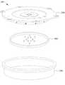
图1A是绘示根据本揭露的一些实施例的进气装置的爆炸图;FIG. 1A is an exploded view illustrating an air intake device according to some embodiments of the present disclosure;
图1B是绘示于组装图1A的进气装置后,沿着进气装置的中心轴剖切的剖视示意图;1B is a schematic cross-sectional view taken along the central axis of the air intake device after assembling the air intake device of FIG. 1A;
图2A是绘示根据本揭露的一些实施例的进气单元的立体示意图;2A is a schematic perspective view illustrating an air intake unit according to some embodiments of the present disclosure;
图2B是绘示根据本揭露的一些实施例的进气单元的仰视示意图;2B is a schematic bottom view illustrating an air intake unit according to some embodiments of the present disclosure;
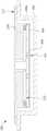
图2C是绘示沿着图2B的剖切线A-A’剖切的进气单元的剖视示意图;Figure 2C is a schematic cross-sectional view of the intake unit cut along the line A-A' of Figure 2B;
图2D是绘示沿着图2B的剖切线B-B’剖切的进气单元的剖视示意图;Figure 2D is a schematic cross-sectional view of the intake unit cut along the section line B-B' in Figure 2B;
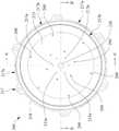
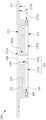
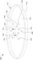
图2E是绘示根据本揭露的一些实施例的进气单元的侧视示意图;2E is a schematic side view illustrating an air intake unit according to some embodiments of the present disclosure;
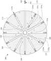
图2F是绘示沿着图2E的剖切线C-C’剖切的进气单元的剖视示意图;Figure 2F is a schematic cross-sectional view of the air intake unit cut along the section line C-C' in Figure 2E;
图2G是绘示沿着图2E的剖切线D-D’剖切的进气单元的剖视示意图;Fig. 2G is a schematic cross-sectional view of the intake unit cut along the section line D-D' of Fig. 2E;
图3是绘示根据本揭露的一些实施例的气体分散单元的立体示意图;3 is a schematic perspective view illustrating a gas dispersion unit according to some embodiments of the present disclosure;
图4是绘示根据本揭露的一些实施例的气体分散板的立体示意图;4 is a schematic perspective view illustrating a gas dispersion plate according to some embodiments of the present disclosure;
图5是绘示于组装图1A的进气装置后,沿着进气装置的中心轴剖切的气体反应系统的剖视示意图;5 is a schematic cross-sectional view of the gas reaction system cut along the central axis of the intake device after assembling the intake device of FIG. 1A;
图6是绘示根据本揭露的一些实施例的气体反应系统的清洗方法的流程示意图。FIG. 6 is a schematic flowchart illustrating a cleaning method of a gas reaction system according to some embodiments of the present disclosure.
具体实施方式detailed description
以下的揭露提供了许多不同的实施例或例子,以实施发明的不同特征。以下所描述的构件与安排的特定例子是用以简化本揭露。当然这些仅为例子,并非用以做为限制。举例而言,在描述中,第一特征形成于第二特征上方或上,可能包含第一特征与第二特征以直接接触的方式形成的实施例,而也可能包含额外特征可能形成在第一特征与第二特征之间的实施例,如此第一特征与第二特征可能不会直接接触。此外,本揭露可能会在各例子中重复参考数字及/或文字。这样的重复是基于简单与清楚的目的,以其本身而言并非用以指定所讨论的各实施例及/或配置之间的关系。The following disclosure provides many different embodiments, or examples, for implementing different features of the invention. Specific examples of components and arrangements are described below to simplify the present disclosure. Of course, these are examples only and are not intended to be limiting. For example, in the description, a first feature is formed on or on a second feature, may include embodiments where the first feature is formed in direct contact with the second feature, and may also include that additional features may be formed on the first feature. An embodiment between a feature and a second feature such that the first feature and the second feature may not be in direct contact. In addition, this disclosure may repeat reference numerals and/or text in various examples. Such repetition is for simplicity and clarity and is not, by itself, intended to dictate a relationship between the various embodiments and/or configurations discussed.
另外,在此可能会使用空间相对用语,以方便描述来说明如附图所绘示的一元件或一特征与另一(另一些)元件或特征的关系。除了在图中所绘示的方向外,这些空间相对用词意欲含括元件在使用或操作中的不同方位。设备可能以不同方式定位(旋转90度或在其他方位上),因此可利用同样的方式来解释在此所使用的空间相对描述符号。In addition, spatially relative terms may be used herein to illustrate the relationship between an element or a feature and another (other) elements or features as shown in the drawings for convenience of description. These spatially relative terms are intended to encompass different orientations of elements in use or operation in addition to the orientation depicted in the figures. A device may be oriented differently (rotated 90 degrees or at other orientations) and thus the spatially relative descriptors used herein may be interpreted in the same manner.
当进行晶圆修饰或形成薄膜层的步骤时,虽然气体分子可与晶圆间产生反应变化,但气体分子亦会沉积于气体反应系统中各组件的表面上,而形成沉积污染物,因此降低系统的清洁度。When modifying the wafer or forming a thin film layer, although the gas molecules can react with the wafer, the gas molecules will also be deposited on the surface of each component in the gas reaction system to form deposition pollutants, thus reducing the System cleanliness.
在进行多次的操作后,气体反应系统的腔体与内部各组件上所积聚的沉积污染物会越来越多,这些沉积污染物若不加以去除,制程良率和产品的稳定性将被影响。其中,随着各组件与系统加热源的距离缩小,污染物沉积的状况越严重。因此,必须周期性地对气体反应系统进行清洗制程,以去除这些沉积污染物。气体反应系统的清洗制程是将清洗气体(例如:三氟化氮(NF3))通入气体反应系统中,以去除(蚀刻)沉积污染物。在清洗制程中,由于清洗气体是由气体反应系统的进气装置导入,且其流道无法任意改变,故清洗气体的流量无法针对各别脏污区域进行调控,而减弱清洗效果,且耗费过量的清洗气体。此外,虽然清洗气体可去除前述的沉积污染物,但清洗气体亦会腐蚀系统中的各组件的表面保护层,而缩短各组件的使用寿命。After repeated operations, more and more depositional pollutants will accumulate on the cavity and internal components of the gas reaction system. If these depositional pollutants are not removed, the process yield and product stability will be affected. influences. Among them, as the distance between each component and the heating source of the system decreases, the condition of pollutant deposition becomes more serious. Therefore, the gas reaction system must be periodically cleaned to remove these deposited contaminants. The cleaning process of the gas reaction system is to pass a cleaning gas (for example: nitrogen trifluoride (NF3 )) into the gas reaction system to remove (etch) deposited pollutants. In the cleaning process, since the cleaning gas is introduced by the gas inlet device of the gas reaction system, and its flow path cannot be changed arbitrarily, the flow rate of the cleaning gas cannot be adjusted for each dirty area, which weakens the cleaning effect and consumes too much purge gas. In addition, although the cleaning gas can remove the aforementioned deposited pollutants, the cleaning gas will also corrode the surface protection layer of each component in the system, thereby shortening the service life of each component.
因此,本揭露揭示一种进气装置、气体反应系统与其清洗方法。通过本揭露的进气装置,于清洗气体反应系统时,清洗气体从进气单元的侧面流出的总侧面流量与清洗气体从底表面流出的总底面流量可被适当地调整,而可提升清洗气体的清洗效果,并延长气体反应系统中各组件的使用寿命。Therefore, the present disclosure discloses an intake device, a gas reaction system and a cleaning method thereof. Through the air intake device disclosed in the present disclosure, when cleaning the gas reaction system, the total side flow rate of the cleaning gas flowing out from the side of the air intake unit and the total bottom surface flow rate of the cleaning gas flowing out from the bottom surface can be adjusted appropriately, and the cleaning gas can be improved. Excellent cleaning effect and prolong the service life of each component in the gas reaction system.
请参照图1A与图1B,其中图1A是绘示根据本揭露的一些实施例的进气装置的爆炸图,且图1B是绘示于组装图1A的进气装置后,沿着进气装置的中心轴剖切的剖视示意图。进气装置100包含进气单元200、气体分散单元300与气体分散板400。气体分散单元300固设于进气单元200下,且进气单元200容置于气体分散单元300的凹陷部300a中。进气单元200具有向外突伸的固定部217,且固定部217是配置以固定并承载进气单元200于气体分散单元300上。其中,固定部217可通过螺设的方式固定于气体分散单元300上。气体分散板400固设于进气单元200的底表面213,且气体分散板400是位于进气单元200与气体分散单元300之间,其中气体分散板400与气体分散单元300相隔一间距。在一些实施例中,气体分散板400可通过螺设、嵌设、紧配合、其他适当的方式,或上述方法的任意组合来设置于进气单元200的底表面213上。Please refer to FIG. 1A and FIG. 1B , wherein FIG. 1A is an exploded view of an air intake device according to some embodiments of the present disclosure, and FIG. 1B is a diagram showing the air intake device along the air intake device after assembling the air intake device of FIG. 1A Schematic cutaway view of the central axis. The
以下分别详细描述进气装置100的进气单元200、气体分散单元300与气体分散板400。The
请参照图2A与图2B。图2A是绘示根据本揭露的一些实施例的进气单元的立体示意图,且图2B是绘示根据本揭露的一些实施例的进气单元的仰视示意图。进气单元200的本体210包含顶表面211、底表面213与连接顶表面211与底表面213的侧面215。顶表面211具有顶面开孔211a,底表面213具有多个底面开孔213a,且侧面215具有多个侧面开孔215a。进气单元200具有第一流道220与第二流道230,其中第一流道220贯穿本体210的顶表面211与底表面213。如图2A所示,虽然所绘示的第一流道220是位于本体210的轴心位置,但本揭露的第一流道220不以此为限。在其他实施例中,第一流道220可根据进气装置的需求,及/或气体反应的要求调整设置位置。在一些具体例中,第一流道220是配置以通入反应气体至进气单元200中,且第二流道230是配置以通入清洗气体至进气单元200中。Please refer to FIG. 2A and FIG. 2B . FIG. 2A is a schematic perspective view of an air intake unit according to some embodiments of the present disclosure, and FIG. 2B is a schematic bottom view of the air intake unit according to some embodiments of the present disclosure. The
请同时参照图2B与图2C,其中图2C是绘示沿着图2B的剖切线A-A’剖切的进气单元的剖视示意图。第二流道230包含多个第一子流道231,其中每一个第一子流道231均是由流道231a、流道231c与连通流道231a与流道231c的流道231b所组成。流道231a连通顶面开孔211a,流道231b连通侧面开孔215a,且流道231c连通底面开孔213a。流道231a是相邻于第一流道220,并由本体210的顶表面211朝向底表面213延伸,但不贯穿底表面213。流道231b的一端连通流道231a,且流道231b的另一端连通侧面开孔215a。流道231c的一端连通流道231b,且流道231c的另一端连通底面开孔213a。据此,当清洗气体通入第一子流道231时,清洗气体可经由第一子流道231的流道231a、流道231b与流道231c,从本体210的侧面215和底表面213流出。在一些实施例中,沿着垂直于气体流动方向的方向剖切,流道231a、流道231b与流道231c的流道截面积可为相同的。Please refer to FIG. 2B and FIG. 2C at the same time, wherein FIG. 2C is a schematic cross-sectional view of the air intake unit cut along the cutting line A-A' of FIG. 2B . The
如图2C所示,虽然流道231c与流道231b的连通位置和流道231a与流道231b的连通位置之间具有一距离,但本揭露的流道231c的设置位置不以此为限。在一些实施例中,流道231c可为流道231a的延伸(即第一子流道231为T字型),但流道231c的流道截面积是不大于流道231a的流道截面积。在其他实施例中,当流道231c为流道231a的延伸时,流道231c的流道截面积是小于流道231a的流道截面积,以避免大部分清洗气体直接经由流道231c从底面开孔213a流出。As shown in FIG. 2C , although there is a distance between the communication position of the
在一些实施例中,底面开孔213a的设置位置可根据流道231c进行调整,或者依据由底表面流出的清洗气体流场的要求进行调整。举例而言,流道231c可不垂直于底表面213(即流道231c的气体流动方向与底表面213间的夹角为锐角),以调整从底表面213流出的清洗气体的流场与流量。In some embodiments, the position of the
请同时参照图2B与图2D,其中图2D是绘示沿着图2B的剖切线B-B’剖切的进气单元的剖视示意图。第二流道230包含多个第二子流道233,其中每一个第二子流道233均是由流道233a与流道233b所组成。流道233a相邻于第一流道220,且流道233a连通顶面开孔211a,并朝向底表面213延伸,但不贯穿底表面213。流道233b的一端连通流道233a,且流道233b的另一端连通侧面开孔215a。因此,当清洗气体通入第二子流道233时,清洗气体是经由流道233a与流道233b,从本体210的侧面215流出。在一些实施例中,沿着垂直于气体流动方向的方向剖切,流道233a与流道233b的流道截面积可为相同的。Please refer to FIG. 2B and FIG. 2D at the same time, wherein FIG. 2D is a schematic cross-sectional view of the air intake unit cut along the section line BB' in FIG. 2B . The
请参照图2C与图2D。每一个第一子流道231与第二子流道233均可设有调节元件240,其中调节元件240是设置于流道231b与流道233b中。在一些实施例中,调节元件240是相邻于侧面215。在一些实施例中,每一个调节元件240不突出本体210的侧面215。在这些实施例中,调节元件240与侧面215可具有间距,以调整从侧面215流出的气体流场。在其他实施例中,调节元件240中远离第一流道220的端面是切齐本体210的侧面215。调节元件240可通过螺设、紧配合、嵌设,或其他适当的方式设置于流道231b与流道233b中。在一些实施例中,调节元件240是可拆卸的,以满足不同的应用需求。每一个调节元件240均具有通道241。在一些实施例中,通道241的流道截面积实质小于所设置的流道231b的流道截面积。在一些实施例中,通道241可为贯穿孔、由多个子流道复合组成的通道,或其他具有适当结构的流道。在一些实施例中,当通道241为贯穿孔时,贯穿孔的孔径是固定不变的。举例而言,当通道241为贯穿孔时,贯穿孔的孔径介于约1.5毫米至约4.5毫米。在其他实施例中,当通道241为贯穿孔时,贯穿孔的孔径可为渐变的,以使经由通道241从侧面215流出的清洗气体可具有不同的喷出流场。Please refer to FIG. 2C and FIG. 2D . Each of the
请参照图2E与图2F。图2E是绘示根据本揭露的一些实施例的进气单元的侧视示意图,且图2F是绘示沿着图2E的剖切线C-C’剖切的进气单元的剖视示意图。其中,剖切线C-C’通过每一个侧面开孔215a。第一子流道231的流道231a与第二子流道233的流道233a是彼此连通的,且流道231a与流道233a是于相邻于第一流道220的位置相连通。因此,当清洗气体经由顶面开孔211a通入第二流道230时,清洗气体可同时通入第一子流道231的流道231a与第二子流道233的流道233a中,并分别经由流道231b、流道233b与调节元件240的通道241,从本体210的侧面开孔215a流出,以及经由流道231c,从底面开孔213a流出。Please refer to FIG. 2E and FIG. 2F . FIG. 2E is a schematic side view of the air intake unit according to some embodiments of the present disclosure, and FIG. 2F is a schematic cross-sectional view of the air intake unit taken along line C-C' in FIG. 2E . Wherein, the cutting line C-C' passes through each
在其他实施例中,流道231a与流道233a可不彼此连通。因此,清洗气体可分别经由流道231a与流道233a通入进气单元200中。在这些实施例中,当流道231a与流道233a不彼此连通时,通入流道231a的清洗气体可不同于通入流道233a的清洗气体,以满足不同的应用需求。其中,流道231b、流道231c与流道233b的流道截面积,以及调节元件240的通道241可适当地被调整,以满足不同的应用需求。In other embodiments, the
当通入清洗气体至第二流道230时,从侧面开孔215a流出的清洗气体是依序通过流道231a、流道231b与调节元件240的通道241,或者依序通过流道233a与调节元件240的通道241,且从底面开孔213a流出的清洗气体是依序通过流道231a、流道231b与流道231c。因此,通过调整调节元件240的通道241的流道截面积,从侧面开孔215a流出的气体总量与从底面开孔213a流出的气体总量可被适当地控制。可理解的是,从侧面开孔215a流出的气体总量与从底面开孔213a流出的气体总量是通过调整通道241的总流道截面积与底面开孔213a的总开口截面积的面积比值来改变。举例而言,此面积比值介于约0.42至约3.48。当面积比值为此范围时,从进气单元200流出的清洗气体可更有效地清洁后述的气体分散单元300,而可减少清洗气体的用量,并避免过量清洗气体所导致的过度清洁。When the cleaning gas is passed into the
请继续参照图2F。依据底面开孔213a的设置位置,第一子流道231与第二子流道233是放射状地交错设置。如图2F所示,虽然第一子流道231的流道231b与第二子流道233的流道233b是以一对一的方式放射状地交错设置,但本揭露不以此为限。在一些实施例中,流道231b与流道233b可以数量不相等的方式放射状地交错设置。在其他实施例中,流道231b与流道231c可放射状地,并以随机排列的方式设置。Please continue to refer to FIG. 2F. According to the positions of the
请参照图2E与图2G,其中图2G是绘示沿着图2E的剖切线D-D’剖切的进气单元的剖视示意图。进气单元200可包含冷却流道255,且冷却流道255是连通设置于顶表面210的冷却流体入口251与冷却流体出口253(如图2A所示),其中冷却流道255可避免通入进气单元200的气体因高温沉积于第一流道220与第二流道230中。冷却流道255的设置位置没有特别的限制,其仅须避免干扰第二流道230即可。冷却流道255和第二流道230的流道231b与流道233b(如图2F所示)可设置于不同的水平高度,而可兼顾进气单元200的进气效果与冷却流道255的冷却效果。Please refer to FIG. 2E and FIG. 2G , wherein FIG. 2G is a schematic cross-sectional view of the air intake unit cut along the section line D-D' in FIG. 2E . The
进一步地,在一些实施例中,如图1B与图2B所示,由本体210向外突伸的固定部217的底面可具有定位结构217a,且气体分散单元300可具有相应的定位结构,以确保进气单元200固定于适当的位置。在一些实施例中,固定部217的底面可设有容纳槽217b,以容置气密件,而可避免经由第一流道220或第二流道230所通入的气体由进气单元200与进气分散单元300间逸散。另外,本体210的底表面213具有多个固定孔260,且气体分散板400可通过这些固定孔260固设于进气单元200的底表面213上。在一些实施例中,固定孔260的设置位置可依据气体分散板400的固定方式调整。Further, in some embodiments, as shown in FIG. 1B and FIG. 2B , the bottom surface of the fixing
请同时参照图1B、图2A与图3,其中图3是绘示根据本揭露的一些实施例的气体分散单元的立体示意图。气体分散单元300包含向外突伸的凸缘310,且进气单元200是通过向外突伸的固定部217固设于气体分散单元300的凸缘310上,其中气体分散单元300是位于进气单元200之下。在一些实施例中,气体分散单元300的凸缘310可通过螺设、嵌设、卡固、其他适当的固定方式,或上述方法的任意组合来固定于进气单元200的固定部217下。气体分散单元300具有凹陷部300a,且进气单元200可容置于此凹陷部300a中。气体分散单元300的侧壁330的内表面与进气单元200的侧面215可具有一间距,以使清洗气体可顺畅地由进气单元200的侧面开孔215a流出,而不会被侧壁330的内表面阻挡。气体分散单元300的底板320设有多个第一气体贯穿孔321,故经由进气单元200流入凹陷部300a的清洗气体可进一步通过第一气体贯穿孔321,而均匀地由气体分散单元300分散流出。须说明的是,第一气体贯穿孔321是微小且密集分布于底板320上的贯穿孔,故为方便绘图起见,底板320的第一气体贯穿孔321是被省略。Please refer to FIG. 1B , FIG. 2A and FIG. 3 at the same time, wherein FIG. 3 is a schematic perspective view illustrating a gas dispersion unit according to some embodiments of the present disclosure. The
请参照图1B、图2C与图4,图4是绘示根据本揭露的一些实施例的气体分散板的立体示意图。气体分散板400的板体410具有凸缘411、多个第二气体贯穿孔420、多个气体通道430与固定结构440。凸缘411是设于板体410的周缘,并由板体410的周缘向上突伸。第二气体贯穿孔420是设置于板体410上,并贯穿板体410。气体通道430与固定结构440是设置于板体410上,并由板体410向上突伸。每一个气体通道430均具有气体流道431,且气体流道431是延伸贯穿板体410。气体分散板400是通过固定结构440与进气单元200的底表面213的固定孔260(如图2B所示)固设于进气单元200下,而使板体410、凸缘411与进气单元200的底表面213形成一空间,且进气单元200的第一流道220是连通此空间。故,经由进气单元200的第一流道220通入的反应气体可流入此空间中,并通过第二气体贯穿孔420均匀且分散地流入气体分散板400与气体分散单元300之间的凹陷部300a。须说明的是,第二气体贯穿孔420是微小且密集分布于板体410上的贯穿孔,故为方便绘图起见,板体410的第二气体贯穿孔420是被省略。Please refer to FIG. 1B , FIG. 2C and FIG. 4 . FIG. 4 is a perspective view illustrating a gas dispersion plate according to some embodiments of the present disclosure. The
气体通道430的气体流道431是以一对一的方式连通进气单元200的底表面213的底面开孔213a。因此,当气体由底面开孔213a流出时,气体是直接经由气体流道431流过气体分散板400,并流至凹陷部300a中。换言之,当气体由底面开孔213a流出时,气体不会流入前述板体410、凸缘411与底表面213所形成的空间中,故气体不会经过第二气体贯穿孔420。The
请参照图1B、图2C与图2D所示,当通入清洗气体至进气单元200的第二流道230时,部分气体可流入第一子流道231中,且剩余气体可流入第二子流道233中。依据前述的说明可知,流入第一子流道231的气体的一部分可经由流道231a、流道231b与流道231c,从进气单元200的底面开孔213a流入气体分散板400的气体通道430的气体流道431中,而通过气体分散板400,直接流至凹陷部300a中。其次,流入第一子流道231的气体的剩余部分可经由流道231a、流道231b与调节元件240的通道241,从进气单元200的侧面开孔215a流入凹陷部300a中。另外,流入第二子流道233的气体可经由流道233a、流道233b与调节元件240的通道241,从进气单元200的侧面开孔215a流入凹陷部300a中。据此,通入第二流道230的清洗气体可绕过(by-pass)气体分散板400,而直接通入气体分散单元300的凹陷部300a中,进而从气体分散单元300的第一气体贯穿孔321(如图3所示)均匀且分散地流出。Please refer to FIG. 1B, FIG. 2C and FIG. 2D, when the cleaning gas is passed into the
请参照图5,其是绘示于组装图1A的进气装置后,沿着进气装置的中心轴剖切的气体反应系统的剖视示意图。气体反应系统500包含腔体510、进气装置100与加热装置520,其中进气装置100是设置于腔体510的顶开口,并形成腔体空间。加热装置520设置于腔体空间中,且加热装置520是配置以承载待处理的晶圆。Please refer to FIG. 5 , which is a schematic cross-sectional view of the gas reaction system cut along the central axis of the air intake device after assembling the air intake device in FIG. 1A . The
请同时参照图3至图5。当晶圆欲进行气体反应时,进气装置100可先移除,并将待处理晶圆放置于加热装置520上。在一些具体例中,腔体510可设有移动结构,且进气装置100是设置于此移动结构上,而可通过此移动结构来移除进气装置100。当放置晶圆后,归位进气装置,并同时利用加热装置520加热晶圆,且经由进气单元200的第一流道220,利用反应气体供应装置通入反应气体。所通入的反应气体可先充满于进气单元200与气体分散板400间的空间,并逐渐通过气体分散板400的板体410的第二气体贯穿孔420,而均匀且分散地流入气体分散单元300的凹陷部300a中。当反应气体充满凹陷部300a时,反应气体可进一步经由气体分散单元300的第一气体贯穿孔321均匀且分散地流入腔体空间中,并反应沉积于晶圆表面。未反应的剩余气体可经由腔体排气道511排出。待反应完成后,停止加热,移除进气装置100,并取出晶圆,即可对晶圆进行接续的处理和/或操作。Please refer to Figure 3 to Figure 5 at the same time. When the wafer is going to undergo gas reaction, the
随着反应的进行,因为气体分散单元300较靠近加热装置520,故反应气体易沉积于气体分散单元300的表面上,而降低气体反应系统500的制程良率和产品的稳定性。据此,气体反应系统500须进行清洗制程,以提升制程良率和产品的稳定性,并延长各组件的使用寿命。如图2D与图3至图5所示,清洗气体是通过清洗气体供应装置通入进气装置100的进气单元200的第二流道230中。所通入的部分清洗气体可流入第一子流道231中,且剩余清洗气体可流入第二子流道233中。流入第一子流道231的清洗气体的一部分可经由流道231a、流道231b与流道231c,从底面开孔213a流入气体分散板400的气体通道430的气体流道431中,而流入凹陷部300a中。流入第一子流道231的清洗气体的剩余部分可经由流道231a、流道231b与调节元件240的通道241,从侧面开孔215a流入凹陷部300a中。流入第二子流道233的清洗气体可经由流道233a、流道233b与调节元件240的通道241,从侧面开孔215a流入凹陷部300a中。据此,当进行清洗制程时,由进气单元200通入的清洗气体系绕过气体分散板400,而直接流入气体分散单元300的凹陷部300a中,进而可清洗气体分散单元300的内表面。再者,充斥于凹陷部300a的清洗气体可经由气体分散单元300的第一气体贯穿孔321均匀且分散地流入腔体空间中。As the reaction progresses, because the
当进行清洗制程时,通过调整调节元件240的通道241的流道截面积,由进气单元200的侧面开孔215a流出的总气体量与从气体分散板400的气体通道431流出的总气体量(即从底面开孔213a流出的总气体量)的比值可被调整,而可针对气体分散单元300中各区域的脏污程度,对应调整通入的气体量,以有效清洗气体分散单元300,并避免气体分散单元300被过度清洗,进而减少清洗气体的使用量。在一些实施例中,依据清洗气体欲达成的流场,调节元件240的通道241的流道截面积可为渐变的,且流道231b、流道233b与流道231c可不垂直于进气单元200的侧面215或底表面213。在一些实施例中,调节元件240的通道241可为贯穿孔、由多个子流道复合组成的通道,或其他具有适当结构的流道。举例而言,当调节元件240为贯穿孔时,贯穿孔的孔径介于约1.5毫米至约4.5毫米。相较于气体分散单元300的侧壁330的内表面,由于反应气体一般较易沉积于气体分散单元300的底板320的内表面,故清洗气体从进气单元200的底表面213流出的总底面流量须大于清洗气体从侧面215流出的总侧面流量,以更有效地清洗气体分散单元300。在一些具体例中,所有通道241的总开口面积与进气单元200的底表面213的气体开孔213a的总开口截面积的比值介于约0.42至约3.48,以有效提升清洗气体的清洗效果。When performing the cleaning process, by adjusting the channel cross-sectional area of the
由于气体反应系统500的进气装置100的进气单元200中的第一流道220与第二流道230彼此独立,故反应气体与清洗气体可经由不同的流道流入进气装置100中。据此,调节清洗气体的流量的调节元件240可预先设置于第二流道230的流道231b与流道233b中,以于清洗进气装置100的气体分散单元300时,调控清洗气体的总侧面流量与总底面流量,以有效清洗气体分散单元300,并避免过度清洗的缺陷。在其他实施例中,根据气体反应系统500的污染物的沉积程度,调节元件240的通道241的流道截面积可被调整,以调控清洗气体的总侧面流量与总底面流量。在这些实施例中,调整通道241的流道截面积的操作可通过更换具有不同通道241的调节元件240来进行。Since the
据此,通过调节元件的设置,气体经由本揭露的气体反应系统的进气装置的侧面流出的总侧面流量,以及从进气装置的底面流出的总底面流量可被适当地调控,而可有效地针对沉积物的污染程度对气体反应系统的各组件进行清洗制程,进而减少清洗气体的使用量,避免过量气体所导致的过度清洗(蚀刻),并可有效延长气体反应系统的使用寿命。Accordingly, through the setting of the adjusting element, the total side flow rate of the gas flowing out from the side of the air inlet device of the gas reaction system of the present disclosure, and the total bottom surface flow rate of the gas flow out from the bottom surface of the air inlet device can be properly regulated, and can be effectively The components of the gas reaction system are cleaned according to the degree of contamination of the deposits, thereby reducing the amount of cleaning gas used, avoiding excessive cleaning (etching) caused by excessive gas, and effectively extending the service life of the gas reaction system.
请同时参照图5与图6,图6是绘示根据本揭露的一些实施例的气体反应系统的清洗方法的流程示意图。于清洗方法600中,气体反应系统500是先被提供,如操作610所示。气体反应系统500包含进气装置100、腔体510与加热装置520,其中进气装置100是设置于腔体510的顶开口,而可形成腔体空间。加热装置520是设置于腔体空间中,且于进行气体反应时,加热装置520是用以承载晶圆。Please refer to FIG. 5 and FIG. 6 at the same time. FIG. 6 is a schematic flowchart illustrating a cleaning method of a gas reaction system according to some embodiments of the present disclosure. In
进气装置100包含进气单元200、气体分散单元300与气体分散板400,且气体分散板400是位于进气单元200与气体分散单元400之间。气体分散单元300是固设于进气单元200的固定部217,且气体分散板400是固设于进气单元200的底表面213。The
如图3与图5所示。进气单元200是设置于气体分散单元300的容置部300a中。其中,进气单元200可通过突伸的固定部217固定于气体分散单元300的凸缘310上。气体分散单元300的底板320设有多个第一气体贯穿孔321。当进气单元200与气体分散单元300结合时,进气单元200的侧面215与气体分散单元300的侧壁330的内表面具有一间距,以避免侧壁330阻碍气体的流动。As shown in Figure 3 and Figure 5. The
如图4与图5所示。气体分散板400的板体410具有凸缘411、多个第二气体贯穿孔420、多个气体通道430与固定结构440。凸缘411是设置于板体410的周缘上,且由板体410的周缘向上突伸,且板体410、凸缘411与进气单元200的底表面213可形成一空间。第二气体贯穿孔420设置于板体410上。气体通道430与固定结构440均是设置于板体410上,并向上延伸。气体分散板400是通过固定结构440设置于进气单元200的底表面213下。每一个气体通道430均具有气体流道431,且气体流道431以一对一的方式连通进气单元200的底表面213的底面开孔213a。As shown in Figure 4 and Figure 5. The
如图2A至图2D与图5所示。进气单元200包含本体210、第一流道220与第二流道230。第一流道220贯穿本体210的顶表面211与底表面213。第二流道230包含第一子流道231与第二子流道233。第一子流道231是由流道231a、流道231b与流道231c所组成,且第二子流道233是由流道233a与流道233b所组成。流道231a连通顶表面211的顶面开孔211a,并朝向底表面213延伸,但不贯穿底表面213。流道231b的一端连通流道231a,且另一端连通本体210的侧面215的侧面开孔215a。流道231c连通流道231b与底表面213的底面开孔213a。流道233a连通顶面开孔211a,并朝向底表面213延伸,但不贯穿底表面213。流道233b的一端连通流道233a,且另一端连通侧面开孔215a。As shown in FIG. 2A to FIG. 2D and FIG. 5 . The
于进气装置100中,当清洗气体通入第二流道230时,清洗气体可流入第一子流道231与第二子流道233。流入第一子流道231的清洗气体的一部分可经由流道231a、流道231b与流道231c,并进一步从底面开孔213a流过气体分散板400的气体通道430的气体流道431,而流至凹陷部300a中。流入第一子流道231的清洗气体的剩余部分是经由流道231a与流道231b,从侧面开孔215a流入凹陷部300a中。流入第二子流道233的清洗气体则是经由流道233a与流道233b,从侧面开孔215a流入凹陷部300a中。In the
请同时参照图2D、图5与图6。于进行操作610后,进行评估制程,以获得气体反应系统500的进气装置100的气体分散单元300的脏污评估结果,并根据所获得的脏污评估结果,进行调整制程,如操作620与操作630所示。当进行评估制程时,操作人员可根据气体分散单元300的表面沉积物来评估脏污程度。一般而言,进行评估制程时,气体分散单元300是被划分为两个区域,即靠近中心部的圆形区域与围绕此圆形区域的环状区域。换言之,操作人员是判断圆形区域与环状区域的脏污程度,以获得脏污评估结果。其中,此圆形区域相当于前述进气装置100的气体分散板400的垂直投影所涵盖的范围,而环状区域相当于未被涵盖的范围。可理解的是,所述圆形区域与环状区域的分界线是虚拟分界线,且依据进气装置100的不同,此分界线的位置将有所变动。Please refer to FIG. 2D , FIG. 5 and FIG. 6 at the same time. After
进行调整制程时,于每一个流道231b与每一个流道233b相邻于侧面215的位置,流道231b与流道233b的流道截面积是被调整,以调节气体由进气单元200的侧面215与从底表面213流出的气体量,因而可依据前述的脏污评估结果有效地清洗气体分散单元300的各个区域。When adjusting the process, at the position where each
在一些实施例中,调整制程是设置调节元件240于第一子流道231的每一个流道231b与第二子流道233的每一个流道233b中,且调节元件240的设置位置相邻于进气单元200的侧面215。这些调节元件240均具有通道241,故通过调整通道241的流道截面积,气体从进气单元200的侧面215流出的总气体量可被调整。据此,通过调整通道241的流道截面积,气体从进气单元200的侧面215流出的总侧面流量,以及气体经由气体流道431流出的总底面流量(即经由底面开孔213a流出的总流量)均可被调整。因此,操作人员可调整总侧面流量与总底面流量的比值,而可有效清洗气体分散单元300,且可避免过多的气体从侧面215流出,而导致前述的环状区域被过度腐蚀。In some embodiments, the adjustment process is to arrange the
一般而言,反应气体是由第一流道220通入进气装置100中,且清洗气体是由第二流道230通入进气装置100中。再者,第一流道220不连通第二流道230。因此,反应气体与清洗气体分别是经由独立的流道流入气体分散单元300的凹陷部300a。因此,于通入反应气体时,第二流道的流道参数不会影响反应气体的通入。据此,在一些实施例中,于操作610所提供的气体反应系统500中,进气单元200可选择性地包含调节元件240。调节元件240是设置于每一个流道231b与流道233b中,且相邻于侧面215,其中调节元件240具有通道241。接着,当进气装置100需要被清洗时,依据评估制程所获得的脏污评估结果,操作人员可判断已设置于进气装置100的调节元件240的通道241是否可使总侧面流量与总底面流量满足需求。若无法满足需求,更换具有适当通道241的调节元件240,以调整清洗气体流经通道241的流道截面积,而使清洗气体的总侧面流量与总底面流量满足需求。Generally speaking, the reaction gas is passed into the
进行操作630后,利用清洗气体供应装置通入清洗气体至第二流道230中,以进行清洗制程,如操作640所示。清洗气体可经由第二流道230的第一子流道231与第二子流道233,从侧面215的侧面开孔215a流入气体分散单元300的凹陷部300a中,且从底表面213的底面开孔213a与气体分散板400的气体流道431流入凹陷部300a中,因而可清除气体分散单元300的内表面上的沉积物。由于前述的调整制程调整清洗气体从侧面开孔215a流出的流道截面积,故清洗气体由侧面开孔215a流出的总侧面流量与从气体流道431流出的总底面流量可被控制。在一些具体例中,调节元件240的通道241的总开口截面积与气体开孔213a的总开口截面积的比值为介于约0.42至3.48。After
据此,清洗方法600可通过调整制程来控制清洗气体由侧面215流出的流道截面积,以调整清洗气体的总侧面流量与总底面流量,进而有效清洗气体分散单元300,并使清洗气体不会过于集中于侧面215或底表面213的区域,以避免过量清洗气体对于气体分散单元300的损害,因而可延长气体分散单元300的使用寿命,且可减少清洗气体的用量。Accordingly, the
于本揭露的进气装置、气体反应系统与其清洗方法中,通过设置调节元件于进气装置的进气单元的第二流道中,清洗气体从进气单元的侧面流出的总侧面流量与从进气单元的底表面流出的总底面流量可被调控,以有效针对气体分散单元的脏污区域进行清洗制程,而提升清洗气体的清洗效果,并避免过度清洗的缺陷,因而可减少清洗气体的用量,且延长气体分散单元的使用寿命。其次,反应气体与清洗气体可独立地经由不同的流道流入气体反应系统中,故前述调节元件的设置不会影响反应气体的流场,故进行清洗制程时,操作人员可直接利用清洗气体供应装置来通入清洗气体,而可减少装置切换的频率,以提升气体反应系统的稳定性。In the air intake device, the gas reaction system and its cleaning method of the present disclosure, by setting the regulating element in the second channel of the air intake unit of the air intake device, the total side flow rate of the cleaning gas flowing out from the side of the air intake unit is the same as that from the inlet unit. The total bottom surface flow out of the bottom surface of the gas unit can be adjusted to effectively clean the dirty area of the gas dispersion unit, thereby improving the cleaning effect of the cleaning gas and avoiding the defects of excessive cleaning, thus reducing the amount of cleaning gas used , and prolong the service life of the gas dispersion unit. Secondly, the reaction gas and the cleaning gas can flow into the gas reaction system independently through different flow channels, so the setting of the aforementioned adjustment elements will not affect the flow field of the reaction gas, so when performing the cleaning process, the operator can directly use the cleaning gas supply The device is used to feed the cleaning gas, which can reduce the frequency of device switching and improve the stability of the gas reaction system.
熟悉此技艺者应了解到,并非所有优点须已于此讨论,对于所有实施例或例子,没有特定的优点是必须的,且其他实施例或例子可提供不同的优点。Those skilled in the art will appreciate that not all advantages have to be discussed here, that no particular advantage is required for all embodiments or examples, and that other embodiments or examples may provide different advantages.
根据本揭露的一态样,提出一种进气装置。此进气装置包含进气单元。进气单元包含本体、第一流道、第二流道与多个调节元件。本体包含顶表面、底表面与侧面,且侧面连接顶表面与底表面。顶表面具有顶面开孔、底表面具有多个底面开孔,且侧面具有多个第一侧面开孔与第二侧面开孔。第一流道贯穿本体。第二流道包含多个第一子流道与多个第二子流道。这些第一子流道连通顶面开孔,且以一对一的方式连通第一侧面开孔与底面开孔两者。这些第二子流道连通顶面开孔,且以一对一的方式连通第二侧面开孔。调节元件分别具有多个通道,且这些调节元件是以一对一的方式设置于第一子流道与第二子流道中。According to an aspect of the present disclosure, an air intake device is provided. The air intake device includes an air intake unit. The air intake unit includes a body, a first flow channel, a second flow channel and a plurality of adjustment elements. The body includes a top surface, a bottom surface and a side surface, and the side surface connects the top surface and the bottom surface. The top surface has a top opening, the bottom surface has a plurality of bottom openings, and the side has a plurality of first side openings and second side openings. The first flow channel runs through the body. The second channel includes a plurality of first sub-channels and a plurality of second sub-channels. The first sub-channels communicate with the openings on the top surface, and communicate with the openings on the first side surface and the openings on the bottom surface in a one-to-one manner. The second sub-channels communicate with the top openings and communicate with the second side openings in a one-to-one manner. The adjustment elements respectively have a plurality of channels, and these adjustment elements are arranged in the first sub-channel and the second sub-channel in a one-to-one manner.
依据本揭露的一实施例,第一子流道与第二子流道是交错设置。According to an embodiment of the present disclosure, the first sub-channels and the second sub-channels are arranged alternately.
依据本揭露的一实施例,每一个调节元件不突出进气单元的侧面。According to an embodiment of the present disclosure, each adjustment element does not protrude from the side of the air intake unit.
依据本揭露的一实施例,每一个通道的截面积实质小于调节元件所设置的第二流道的位置的流道截面积。According to an embodiment of the present disclosure, the cross-sectional area of each channel is substantially smaller than the cross-sectional area of the flow channel at the position of the second flow channel where the adjusting element is disposed.
依据本揭露的一实施例,此进气装置还包含气体分散单元与气体分散板。气体分散单元具有凹陷部,且进气单元容置于凹陷部中,其中气体分散单元的底板设有多个第一气体贯穿孔。气体分散板固设于本体的底表面,且位于进气单元与气体分散单元之间。气体分散板包含板体、凸缘与多个气体通道。板体具有多个第二气体贯穿孔。凸缘位于板体的周缘,且板体、凸缘与底表面形成一空间,其中第一流道连通此空间。这些气体通道是由板体的表面突伸至此空间中,且这些气体通道分别以一对一的方式连通抵面开孔。According to an embodiment of the present disclosure, the air intake device further includes a gas dispersion unit and a gas dispersion plate. The gas dispersing unit has a recessed portion, and the air intake unit is accommodated in the recessed portion, wherein the bottom plate of the gas dispersing unit is provided with a plurality of first gas through holes. The gas dispersion plate is fixed on the bottom surface of the main body and is located between the air intake unit and the gas dispersion unit. The gas distribution plate includes a plate body, flanges and multiple gas passages. The plate body has a plurality of second gas penetration holes. The flange is located on the periphery of the plate body, and a space is formed by the plate body, the flange and the bottom surface, wherein the first flow channel communicates with the space. The gas passages protrude from the surface of the plate body into the space, and the gas passages communicate with the openings on the opposite surface in a one-to-one manner.
依据本揭露的一实施例,气体分散单元与气体分散板相隔一间距。According to an embodiment of the present disclosure, the gas dispersion unit and the gas dispersion plate are separated by a distance.
根据本揭露的另一态样,提出一种气体反应系统。此气体反应系统包含腔体、进气装置、反应气体供应装置、清洗气体供应装置与加热装置。此腔体具有一顶开口,且进气装置设置于顶开口,以形成腔体空间于腔体中。反应气体供应装置连通进气装置的进气单元的第一流道,且清洗气体供应装置连通进气单元的第二流道。加热装置是设置于腔体空间中,且此加热装置是位于进气装置下。According to another aspect of the present disclosure, a gas reaction system is provided. The gas reaction system includes a cavity, an air inlet device, a reaction gas supply device, a cleaning gas supply device and a heating device. The cavity has a top opening, and the air inlet device is arranged on the top opening to form a cavity space in the cavity. The reactive gas supply device communicates with the first channel of the air intake unit of the air intake device, and the cleaning gas supply device communicates with the second channel of the air intake unit. The heating device is arranged in the cavity space, and the heating device is located under the air inlet device.
根据本揭露的又一态样,提出一种气体反应系统的清洗方法。此清洗方法是先提供气体反应系统,并进行评估制程,以比较气体分散单元的多个区域的脏污程度,而获得气体分散单元的脏污评估结果。气体反应系统包含腔体、进气装置与加热装置。腔体具有顶开口,且进气装置设置于顶开口,以形成腔体空间于腔体中。进气装置包含进气单元、气体分散单元与气体分散板。进气单元包含第一流道与第二流道。第一流道贯穿进气单元的顶表面与底表面,且第二流道连通进气单元的顶表面的顶面开孔、底表面的多个底面通孔与侧面的多个侧面通孔。气体分散单元具有凹陷部,且进气单元容置于凹陷部中。气体分散单元的底板设有多个气体贯穿孔。气体分散板是固设于进气单元的底表面,且位于进气单元与气体分散单元之间。气体分散板包含多个气体通道,且这些气体通道分别以一对一的方式连通底面开孔。加热装置是设置于腔体空间中,且位于进气装置下。然后,根据脏污评估结果,进行调整制程。调整制程是调整第二流道的多个调整位置的每一者的流道截面积。于进行调整制程后,供给清洗气体至第二流道中,以进行清洗制程。According to another aspect of the present disclosure, a method for cleaning a gas reaction system is provided. In this cleaning method, a gas reaction system is firstly provided, and an evaluation process is performed to compare the degree of contamination of multiple regions of the gas dispersion unit, so as to obtain the contamination evaluation result of the gas dispersion unit. The gas reaction system includes a cavity, an air inlet device and a heating device. The cavity has a top opening, and the air inlet device is arranged on the top opening to form a cavity space in the cavity. The air intake device includes an air intake unit, a gas dispersion unit and a gas dispersion plate. The intake unit includes a first flow channel and a second flow channel. The first flow channel runs through the top surface and the bottom surface of the air intake unit, and the second flow channel communicates with the top opening on the top surface of the air intake unit, the bottom through holes on the bottom surface and the side through holes on the side. The gas dispersing unit has a recessed portion, and the air intake unit is accommodated in the recessed portion. The bottom plate of the gas dispersion unit is provided with a plurality of gas through holes. The gas dispersion plate is fixed on the bottom surface of the air intake unit and is located between the air intake unit and the gas dispersion unit. The gas distribution plate includes a plurality of gas channels, and the gas channels communicate with the openings on the bottom surface in a one-to-one manner. The heating device is arranged in the cavity space and is located under the air intake device. Then, adjust the process according to the result of the contamination evaluation. The adjustment process is to adjust the flow channel cross-sectional area of each of the plurality of adjustment positions of the second flow channel. After the adjustment process is performed, the cleaning gas is supplied to the second channel to perform the cleaning process.
依据本揭露的一实施例,调整制程包含以一对一的方式设置多个调节元件至调整位置中,其中每一个调节元件具有通道。According to an embodiment of the present disclosure, the adjusting process includes disposing a plurality of adjusting elements in an adjusting position in a one-to-one manner, wherein each adjusting element has a channel.
依据本揭露的一实施例,进气单元还包含多个调节元件,且这些调节元件是以一对一的方式设置于调整位置。According to an embodiment of the present disclosure, the air intake unit further includes a plurality of adjustment elements, and these adjustment elements are arranged at adjustment positions in a one-to-one manner.
上述已概述数个实施例的特征,因此熟悉此技艺者可更了解本揭露的态样。熟悉此技艺者应了解到,其可轻易地利用本揭露做为基础,来设计或润饰其他制程与结构,以实现与在此所介绍的实施例相同的目的及/或达到相同的优点。熟悉此技艺者也应了解到,这类对等架构并未脱离本揭露的精神和范围,且熟悉此技艺者可在不脱离本揭露的精神和范围下,在此进行各种的更动、取代与修改。The features of several embodiments have been outlined above, so those skilled in the art can better understand aspects of the present disclosure. Those skilled in the art should appreciate that they can easily use the present disclosure as a basis to design or modify other processes and structures to achieve the same objectives and/or achieve the same advantages as the embodiments described herein. Those familiar with this art should also understand that this type of peer-to-peer architecture does not depart from the spirit and scope of this disclosure, and those familiar with this art can make various changes, replace and modify.
Claims (10)
Translated fromChinesePriority Applications (1)
| Application Number | Priority Date | Filing Date | Title |
|---|---|---|---|
| CN201910120050.6ACN111584336B (en) | 2019-02-18 | 2019-02-18 | Air intake device, gas reaction system and cleaning method thereof |
Applications Claiming Priority (1)
| Application Number | Priority Date | Filing Date | Title |
|---|---|---|---|
| CN201910120050.6ACN111584336B (en) | 2019-02-18 | 2019-02-18 | Air intake device, gas reaction system and cleaning method thereof |
Publications (2)
| Publication Number | Publication Date |
|---|---|
| CN111584336A CN111584336A (en) | 2020-08-25 |
| CN111584336Btrue CN111584336B (en) | 2023-01-10 |
Family
ID=72126021
Family Applications (1)
| Application Number | Title | Priority Date | Filing Date |
|---|---|---|---|
| CN201910120050.6AActiveCN111584336B (en) | 2019-02-18 | 2019-02-18 | Air intake device, gas reaction system and cleaning method thereof |
Country Status (1)
| Country | Link |
|---|---|
| CN (1) | CN111584336B (en) |
Families Citing this family (1)
| Publication number | Priority date | Publication date | Assignee | Title |
|---|---|---|---|---|
| CN114215984B (en)* | 2021-12-14 | 2024-07-09 | 拓荆科技股份有限公司 | Semiconductor device and gas conveying structure thereof |
Citations (4)
| Publication number | Priority date | Publication date | Assignee | Title |
|---|---|---|---|---|
| WO2015030457A1 (en)* | 2013-08-28 | 2015-03-05 | (주)젠 | Plasma apparatus for vapor phase etching and cleaning |
| CN104934313A (en)* | 2014-03-18 | 2015-09-23 | 株式会社日立国际电气 | Substrate processing apparatus and method for manufacturing semiconductor device |
| CN106098548A (en)* | 2015-04-30 | 2016-11-09 | 吉恩株式会社 | For vapor phase etchant and the plasma device of cleaning |
| CN107881484A (en)* | 2016-09-30 | 2018-04-06 | 汉民科技股份有限公司 | Gas injection device applied to semiconductor equipment |
Family Cites Families (1)
| Publication number | Priority date | Publication date | Assignee | Title |
|---|---|---|---|---|
| US20160343595A1 (en)* | 2015-05-19 | 2016-11-24 | Lam Research Corporation | Corrosion resistant gas distribution manifold with thermally controlled faceplate |
- 2019
- 2019-02-18CNCN201910120050.6Apatent/CN111584336B/enactiveActive
Patent Citations (4)
| Publication number | Priority date | Publication date | Assignee | Title |
|---|---|---|---|---|
| WO2015030457A1 (en)* | 2013-08-28 | 2015-03-05 | (주)젠 | Plasma apparatus for vapor phase etching and cleaning |
| CN104934313A (en)* | 2014-03-18 | 2015-09-23 | 株式会社日立国际电气 | Substrate processing apparatus and method for manufacturing semiconductor device |
| CN106098548A (en)* | 2015-04-30 | 2016-11-09 | 吉恩株式会社 | For vapor phase etchant and the plasma device of cleaning |
| CN107881484A (en)* | 2016-09-30 | 2018-04-06 | 汉民科技股份有限公司 | Gas injection device applied to semiconductor equipment |
Also Published As
| Publication number | Publication date |
|---|---|
| CN111584336A (en) | 2020-08-25 |
Similar Documents
| Publication | Publication Date | Title |
|---|---|---|
| KR102524104B1 (en) | Semiconductor processing chamber for improved precursor flow | |
| TWI759741B (en) | Gas distribution showerhead for semiconductor processing | |
| JP4142545B2 (en) | Gas supply device | |
| KR100392318B1 (en) | Spatially uniform gas delivery and pump configuration for large diameter wafers | |
| KR20210158823A (en) | Showerhead for process tool | |
| JP2003324072A (en) | Semiconductor manufacturing equipment | |
| KR20060003909A (en) | Adjustable Gas Dispersion System | |
| JP7620001B2 (en) | Semiconductor processing chamber and method for cleaning same - Patents.com | |
| KR20060059305A (en) | Semiconductor processing equipment | |
| US7368398B2 (en) | Substrate processing apparatus and substrate processing method | |
| US20060086318A1 (en) | Gas diffusion plate | |
| JP6629248B2 (en) | Gas injection device for epitaxial chamber | |
| KR102267923B1 (en) | Deposition apparatus | |
| CN113106421B (en) | ALD spray components and ALD coating equipment | |
| CN111584336B (en) | Air intake device, gas reaction system and cleaning method thereof | |
| KR102210390B1 (en) | Integration of dual remote plasmas sources for flowable cvd | |
| KR20230043056A (en) | System and apparatus for gas distribution | |
| TWI790777B (en) | Semiconductor chamber components for back diffusion control and method for semiconductor processing | |
| CN220106445U (en) | Air inlet nozzle and dry chemical etching equipment | |
| TWI675163B (en) | Inlet device, gas reaction system and method for cleaning thereof | |
| KR20210043810A (en) | Semiconductor manufacturing apparatus | |
| JP2020510307A (en) | Diffuser design for fluidity CVD | |
| KR100686724B1 (en) | Chemical Vapor Deposition Equipment | |
| CN112951696B (en) | Plasma processing equipment, gas baffle structure thereof and plasma processing method | |
| KR20170040815A (en) | Atomic layer thin film deposition apparatus with uniform gas flow |
Legal Events
| Date | Code | Title | Description |
|---|---|---|---|
| PB01 | Publication | ||
| PB01 | Publication | ||
| SE01 | Entry into force of request for substantive examination | ||
| SE01 | Entry into force of request for substantive examination | ||
| GR01 | Patent grant | ||
| GR01 | Patent grant |