CN111580554A - Indoor unmanned aerial vehicle formation flying method based on frame-by-frame identification and generation of original point cloud - Google Patents
Indoor unmanned aerial vehicle formation flying method based on frame-by-frame identification and generation of original point cloudDownload PDFInfo
- Publication number
- CN111580554A CN111580554ACN202010401363.1ACN202010401363ACN111580554ACN 111580554 ACN111580554 ACN 111580554ACN 202010401363 ACN202010401363 ACN 202010401363ACN 111580554 ACN111580554 ACN 111580554A
- Authority
- CN
- China
- Prior art keywords
- point cloud
- uav
- frame
- indoor
- information
- Prior art date
- Legal status (The legal status is an assumption and is not a legal conclusion. Google has not performed a legal analysis and makes no representation as to the accuracy of the status listed.)
- Granted
Links
Images


Classifications
- G—PHYSICS
- G05—CONTROLLING; REGULATING
- G05D—SYSTEMS FOR CONTROLLING OR REGULATING NON-ELECTRIC VARIABLES
- G05D1/00—Control of position, course, altitude or attitude of land, water, air or space vehicles, e.g. using automatic pilots
- G05D1/10—Simultaneous control of position or course in three dimensions
- G05D1/101—Simultaneous control of position or course in three dimensions specially adapted for aircraft
- G05D1/104—Simultaneous control of position or course in three dimensions specially adapted for aircraft involving a plurality of aircrafts, e.g. formation flying
- Y—GENERAL TAGGING OF NEW TECHNOLOGICAL DEVELOPMENTS; GENERAL TAGGING OF CROSS-SECTIONAL TECHNOLOGIES SPANNING OVER SEVERAL SECTIONS OF THE IPC; TECHNICAL SUBJECTS COVERED BY FORMER USPC CROSS-REFERENCE ART COLLECTIONS [XRACs] AND DIGESTS
- Y02—TECHNOLOGIES OR APPLICATIONS FOR MITIGATION OR ADAPTATION AGAINST CLIMATE CHANGE
- Y02T—CLIMATE CHANGE MITIGATION TECHNOLOGIES RELATED TO TRANSPORTATION
- Y02T10/00—Road transport of goods or passengers
- Y02T10/10—Internal combustion engine [ICE] based vehicles
- Y02T10/40—Engine management systems
Landscapes
- Engineering & Computer Science (AREA)
- Aviation & Aerospace Engineering (AREA)
- Radar, Positioning & Navigation (AREA)
- Remote Sensing (AREA)
- Physics & Mathematics (AREA)
- General Physics & Mathematics (AREA)
- Automation & Control Theory (AREA)
- Control Of Position, Course, Altitude, Or Attitude Of Moving Bodies (AREA)
Abstract
Description
Translated fromChinese技术领域technical field
本发明涉及一种基于逐帧识别生成原始点云的室内无人机编队飞行,属于无人机编队飞行技术领域。The invention relates to an indoor drone formation flight based on frame-by-frame identification to generate an original point cloud, and belongs to the technical field of drone formation flight.
背景技术Background technique
几十年来,来自动物行为学、物理学、生物物理学、社会科学和计算机科学等不同学科的科学家们被成群结队的现象出现所吸引。这些现象包括鸟类、鱼类、企鹅、蚂蚁、蜜蜂和人群。随着无人机技术的日渐成熟,应用场景也越来越多,包括高层物流配送、电力线路检测、侦察监视等等。但是这类应用大多基于单机的行为,只能完成相对简单且不需要协作的任务。而在面对更加复杂的任务时且需要多机协作的任务时,必须考虑无人机群体编队。For decades, scientists from diverse disciplines such as ethology, physics, biophysics, social sciences and computer science have been drawn to the phenomenon emerging in droves. These phenomena include birds, fish, penguins, ants, bees and crowds. With the maturity of UAV technology, there are more and more application scenarios, including high-level logistics distribution, power line detection, reconnaissance and surveillance, etc. However, most of these applications are based on the behavior of a single machine, and can only complete relatively simple tasks that do not require collaboration. When faced with more complex tasks and tasks that require multi-machine cooperation, UAV swarm formations must be considered.
近几年,类似于集群行为的多智能体编队飞行吸引了国内外很多学者的研究。对多无人机编队飞行的控制系统越来越多,它们可大致分为室内编队飞行系统和室外编队飞行系统。无论是室内还是室外,编队飞行的首要条件就是获取无人机在三维空间中的位姿信息和无人机间的相对位置信息。室外编队分行主要依靠GPS信号加上地面控制站来获取无人机信息,这一方法相对较成熟。但对于室内相对来说比较封闭的环境,GPS信号很难起作用,这对室内多无人机机协同编队飞行提出了新的挑战。In recent years, multi-agent formation flying similar to swarm behavior has attracted the research of many scholars at home and abroad. There are more and more control systems for multi-UAV formation flight, which can be roughly divided into indoor formation flight systems and outdoor formation flight systems. Whether it is indoor or outdoor, the first condition for formation flight is to obtain the position and attitude information of UAVs in three-dimensional space and the relative position information between UAVs. Outdoor formation branches mainly rely on GPS signals and ground control stations to obtain UAV information, which is relatively mature. However, in a relatively closed indoor environment, it is difficult for GPS signals to work, which poses new challenges for indoor multi-UAV coordinated formation flight.
针对室内无人机编队飞行,传统的捕捉无人机位姿信息的方法是:通过将反光球标记点固定在无人机上,由动态捕捉系统根据无人机上的标记点相互连接而成的刚体的形状或大小来区别不用的无人机,这导致的问题是,由于室内无人机体积本身较小,因此在无人机上固定的标记点构成的刚体形状种类很有限,面对多台无人机,动态捕捉系统将难以区分。再者,标记点由于相对较小,飞行过程中,无人机自身或者周围的无人机可能会将反光球完全遮挡,此时可能会出现在一定时间内将无法获取到无人机的位姿信息的情况,从而导致编队局部发散。因此,面对室内多台无人机编队飞行,一个可靠的同时识别多台无人机在空间中位姿的系统和方法显得尤其重要。For indoor drone formation flying, the traditional method of capturing the position and attitude information of the drone is: by fixing the reflective ball marking points on the drone, the dynamic capture system is connected to the rigid body according to the marking points on the drone. The shape or size of the drone can be used to distinguish different drones. The problem is that due to the small size of the indoor drone itself, the rigid body shapes formed by the fixed marker points on the drone are very limited. Human-machine, motion capture systems will be indistinguishable. Furthermore, since the marked point is relatively small, during the flight, the drone itself or the surrounding drones may completely block the reflective ball. At this time, it may appear that the position of the drone cannot be obtained for a certain period of time. The situation of attitude information, which leads to the local divergence of the formation. Therefore, when multiple UAVs fly in formation indoors, a reliable system and method for simultaneously identifying the poses of multiple UAVs in space is particularly important.
发明内容SUMMARY OF THE INVENTION
为克服现有技术的不足,本发明旨在提出一种基于逐帧识别生成原始点云的室内无人机编队飞行系统方案以解决现有的室内多无人机编队飞行系统中,由于无人机体积较小,利用标记点的方法难以区分多台无人机的技术问题。为此,本发明采用的技术方案是结合分布式编队结构,使用室内动态捕捉系统进行逐帧识别生成原始点云来获取小型无人机编队的飞行轨迹和飞行状态,并配合带有前馈作用的串联PID控制器和人工势场法的轨迹规划方法提出了一套完整的室内多架小型四旋翼无人机协同编队飞行演示验证平台设计方案In order to overcome the deficiencies of the prior art, the present invention aims to propose an indoor drone formation flight system scheme based on frame-by-frame identification and generation of original point clouds, so as to solve the problem in the existing indoor multi-drone formation flight system, due to unmanned aerial vehicles. The size of the drone is small, and it is difficult to distinguish the technical problems of multiple drones by using the method of marking points. For this reason, the technical solution adopted in the present invention is to combine the distributed formation structure, use the indoor dynamic capture system to perform frame-by-frame identification and generate the original point cloud to obtain the flight trajectory and flight status of the small UAV formation, and cooperate with the feedforward effect. The series PID controller and the trajectory planning method of artificial potential field method proposed a complete set of indoor multiple small quadrotor UAV collaborative formation flight demonstration and verification platform design scheme
本系统采用Optitrack室内动态捕捉系统跟踪被反光球标记的无人机。选择室内动态捕捉系统的原因是它在定位方面的高性能:位置误差小于1毫米。与之相比,最先进的分散定位系统——超带宽无线电三角测量方法的位置误差大于10cm,对于本系统的小型无人机来说,误差过大。The system uses the Optitrack indoor dynamic capture system to track UAVs marked by reflective balls. The reason for choosing the indoor motion capture system is its high performance in positioning: the position error is less than 1 mm. In contrast, the state-of-the-art decentralized positioning system, the ultra-bandwidth radio triangulation method, has a position error of more than 10 cm, which is too large for the small UAV of this system.
本系统使用的小型无人机自身主要由以下几个部分组成:主控制器为STM32F405,负责无人机状态估计计算、产生PWM波送至电机驱动;六轴陀螺仪MPU-9250,用于检测无人机自身局部的姿态变化;通信模块为nRF51,可发送或接收2.4GHz的无线电波,负责和上位机的通信。在无人机中部装有可拆卸的小型锂电池,电池可利用板载USB2.0接口直接充电,或者取下单独充电。底部和上部都有拓展口,可拓展led环形灯等等各种模块。电机的类型是小型的空心杯,共由四个空心杯和直径大约为7cm的4个旋翼组成,其中A型和B型旋翼各一对。改造无人机内部软件的方法是利用USB2.0通过对主控芯片STM32F4烧写固件以及控制程序。该机型体积小,适用于密集地层的室内飞行。由于其低惯性,它能在高速碰撞中幸存下来,对人类构成的风险也很小。The small drone used in this system is mainly composed of the following parts: the main controller is STM32F405, which is responsible for the estimation and calculation of the state of the drone, and generates PWM waves to send to the motor drive; the six-axis gyroscope MPU-9250 is used to detect The local attitude change of the drone itself; the communication module is nRF51, which can send or receive 2.4GHz radio waves, and is responsible for communication with the host computer. A detachable small lithium battery is installed in the middle of the drone. The battery can be directly charged using the onboard USB2.0 interface, or it can be removed and charged separately. There are expansion ports on the bottom and top, which can expand various modules such as LED ring lights. The type of motor is a small hollow cup, which consists of four hollow cups and four rotors with a diameter of about 7cm, of which the A-type and B-type rotors each have a pair. The method of transforming the internal software of the drone is to use USB2.0 to burn the firmware and control program to the main control chip STM32F4. This model is small in size and suitable for indoor flight in dense strata. Due to its low inertia, it can survive high-speed collisions and pose little risk to humans.
室内动态捕捉系统有一台PC和多台高速红外摄像头组成,PC上安装Optitrack软件,控制并接收室内动态捕捉系统所获取的无人机编队的数据,并通过以太网将数据传送给地面控制系统;地面控制系统为另一个PC,即无人机编队控制计算机,在该PC上运行Linux操作系统并运行各个功能模块,同时结合ROS操作系统的通信架构实现各个功能间的数据交互。The indoor dynamic capture system consists of a PC and multiple high-speed infrared cameras. The Optitrack software is installed on the PC to control and receive the data of the UAV formation acquired by the indoor dynamic capture system, and transmit the data to the ground control system through Ethernet; The ground control system is another PC, that is, the UAV formation control computer. The PC runs the Linux operating system and runs various functional modules. At the same time, the communication architecture of the ROS operating system is combined to realize the data interaction between the various functions.
室内小型四旋翼无人机编队演示验证平台工作原理为首先通过室内定位系统经过标定构建出室内三维坐标系,通过动态捕捉系统使用逐帧识别生成原始点云方法识别各个无人机,控制动态捕捉系统的PC通过以太网将无人机的数据发送给另一台PC,另一台PC上的各个模块根据数据计算出每架无人机当前的运动状态并计算出合理的飞行轨迹,再通过无线电广播设备将轨迹信息发送至无人机,无人机接收到定位信息和控制指令,根据系统时间和轨迹信息计算当前无人机的期望运动状态,无人机根据自身运动状态和期望运动状态,通过控制器控制算法驱使无人机按照轨迹飞行,最终实现无人机编队飞行。The working principle of the indoor small quadrotor UAV formation demonstration and verification platform is to first construct an indoor three-dimensional coordinate system through the calibration of the indoor positioning system, and then use the dynamic capture system to use frame-by-frame identification to generate the original point cloud method to identify each UAV and control the dynamic capture. The PC of the system sends the data of the drone to another PC through the Ethernet, and each module on the other PC calculates the current motion state of each drone according to the data and calculates a reasonable flight trajectory, and then passes The radio broadcasting equipment sends the trajectory information to the UAV, and the UAV receives the positioning information and control instructions, and calculates the desired motion state of the current UAV according to the system time and trajectory information, and the UAV according to its own motion state and desired motion state , through the controller control algorithm to drive the UAV to fly according to the trajectory, and finally realize the UAV formation flight.
进一步细化的具体步骤是:The specific steps for further refinement are:
步骤1:小型无人机识别Step 1: Small Drone Identification
本发明根据多台高速红外摄像机对无人机进行逐帧识别,并将每一帧图像生成原始的点云图。由于每台摄像机拍摄视角不同,对同一架无人机所得到的点云会有较大的差异,通过迭代最近点的点云匹配算法,通过空间变换将多张点云图像信息融合,以此来并行获取多台无人机在空间中的位姿信息。The invention performs frame-by-frame identification of the drone according to multiple high-speed infrared cameras, and generates an original point cloud image for each frame of images. Due to the different shooting angles of each camera, the point cloud obtained by the same UAV will be quite different. By iterating the point cloud matching algorithm of the nearest point, the information of multiple point cloud images is fused through spatial transformation, so as to To obtain the pose information of multiple UAVs in space in parallel.
3D点云图像的匹配详细步骤如下:The detailed steps for matching 3D point cloud images are as follows:
(4)假设待配准的点云集合为


(5)对于两个点集之间的相似度度量,用如下目标函数表示:(5) For the similarity measure between two point sets, it is expressed by the following objective function:

其中,R为旋转矩阵,T为平移矩阵,即姿态与位置的矩阵表示,
旋转矩阵R和平移矩阵T为:The rotation matrix R and translation matrix T are:

T=[q4 q5 q6]TT=[q4 q5 q6 ]T
(6)设点云的集合p′和X的中心为


得到平均值后,分别求出两个点云集合的协方差矩阵为:After obtaining the average value, the covariance matrices of the two point cloud sets are calculated as:

其中利用反对称矩阵:where antisymmetric matrices are used:

构建得到列向量:Build the resulting column vector:
Δ=[A23 A31 A12]TΔ=[A23 A31 A12 ]T
最终构建出以下目矩阵:Finally, the following project matrix is constructed:

其中tr(∑px)表示矩阵∑px的迹,即主对角线元素的总和,也就是特征值之和。where tr(∑px) represents the trace of the matrix ∑px, that is, the sum of the main diagonal elements, that is, the sum of the eigenvalues.
(4)代入数据后,对Q矩阵作特征值分解,求得最大的特征值以及对应的特征向量。此特征向量即为对应误差平方和最小时的四元数。将求得的四元数代入矩阵R中,即可求出旋转矩阵,平移矩阵T可通过两个点云集合的中心关系,平移得到。(4) After substituting the data, decompose the eigenvalue of the Q matrix to obtain the largest eigenvalue and the corresponding eigenvector. This eigenvector is the quaternion corresponding to the minimum sum of squared errors. The rotation matrix can be obtained by substituting the obtained quaternion into the matrix R, and the translation matrix T can be obtained by translation through the center relationship of the two point cloud sets.
(5)重复迭代以上4个步骤,直至求出的
步骤2:设计带有前馈作用的串联PID控制器Step 2: Design a series PID controller with feedforward action
本系统的控制器是非线性位置控制器,增加了位置和偏航误差的积分项。控制输入是当前状态(P,V,q,ωm)以及位置偏微分方程Pdes、速度偏微分方程Vdes、加速度偏微分方程
ep=pdes-p,ev=vdes-vep =pdes -p, ev =vdes -v
分别计算所需的力向量,如下所示:Calculate the required force vectors separately as follows:

其中Kp,Ki,Kv是正对角增益矩阵where Kp , Ki , Kv are positive diagonal gain matrices
期望的物体旋转矩阵Rdes是一个关于Fdes、ψdes的函数。方向误差计算如下The desired object rotation matrix Rdes is a function of Fdes , ψdes . The direction error is calculated as follows

其中R是是姿态四元数q的矩阵形式,(·)V是V算子映射S03→R3,where R is the matrix form of the attitude quaternion q, ( )V is the V operator map S03→R3 ,
然后用另一个PID控制器计算所需的矩:Then calculate the required torque with another PID controller:

正对角线增益矩阵K0,Km,Kω.一个简单的线性映射可以计算出Mdes和Fdes到z轴的投影所需要的平方向速度.Positive diagonal gain matrices K0 , Km , Kω . A simple linear mapping can calculate the required planar velocity for the projection of Mdes and Fdes to the z-axis.
Fdes中的位置误差积分补偿了由于不对称(x;y部分)导致的电池电压降(z部分)和质心不平衡。从Mdes中的姿态误差积分出发,只使用z分量,它可以补偿由于螺旋桨和发动机磨损不均造成的偏航误差。手工修整和零件更换可以补偿单一飞行器的这类问题,但在大型飞行器编队中是不可行的。The position error integration in Fdes compensates for the cell voltage drop (z part) and centroid imbalance due to the asymmetry (x;y part). Starting from the attitude error integral in Mdes , using only the z component, it compensates for the yaw error due to uneven wear on the propeller and engine. Manual trimming and parts replacement can compensate for such problems with a single aircraft, but are not feasible in large aircraft formations.
步骤3:基于人工势场法的无人机飞行轨迹规划Step 3: UAV flight trajectory planning based on artificial potential field method
人工势场法(APF)的基本思想是假想目标点对无人机存在引力作用,而障碍物对无人机存在斥力作用,无人机在两种力的共同作用下,靠近目标点并避开障碍物。The basic idea of artificial potential field method (APF) is that the imaginary target point has a gravitational effect on the UAV, while the obstacle has a repulsive force on the UAV. Under the combined action of the two forces, the UAV approaches the target point and avoids it. Open obstacles.
无人机与目标在m维空间中对应的两点之间的真实距离会对引力势场函数造成影响,而斥力势场函数则与该无人机与障碍物之间的欧几里得距离有关。引力势场函数及斥力势场函数如下所示:The true distance between the drone and the target in the m-dimensional space will affect the gravitational potential field function, while the repulsive potential field function is the Euclidean distance between the drone and the obstacle related. The gravitational potential field function and the repulsive potential field function are as follows:


式中,p——无人机的具体位置;In the formula, p——the specific position of the UAV;
pdes——工作空间目标点的位置;pdes ——The position of the workspace target point;
pob——工作空间障碍物的位置;pob - the position of the obstacle in the workspace;
ka——引力势场比例系数;ka ——the proportional coefficient of the gravitational potential field;
kr——斥力势场比例系数;kr — proportional coefficient of repulsive potential field;
ρ(p,pob)——无人机与障碍物在多维空间中的绝对距离;ρ(p, pob )——the absolute distance between the UAV and the obstacle in multi-dimensional space;
ρ0——单个障碍物影响的最大范围。ρ0 ——the maximum range of influence of a single obstacle.
考虑叠加性原理,对两个势场函数进行叠加运算可得到无人机的运动方向和位姿的合成势场函数,无人机所受矢量合力由引力和斥力合成。Considering the principle of superposition, the superposition operation of the two potential field functions can obtain the composite potential field function of the UAV's movement direction and pose, and the vector resultant force on the UAV is composed of gravitational and repulsive forces.
U(p)=Ua(p)+Ur(p)U(p)=Ua (p)+Ur (p)
F(p)=Fa(p)+Fr(p)F(p)=Fa (p)+Fr (p)
与现有技术相比,本发明具有以下优点:Compared with the prior art, the present invention has the following advantages:
(1)解决了现有的室内多无人机编队飞行系统中,由于无人机体积较小,利用标记点的方法难以区分多台无人机的技术问题,提高了四旋翼无人机的协同编队飞行效果;(1) In the existing indoor multi-UAV formation flight system, due to the small size of the UAV, it is difficult to distinguish multiple UAVs by using the method of marking points, which improves the performance of the quadrotor UAV. The effect of coordinated formation flight;
(2)改善了传统演示验证平台通信时滞、丢包等不足,提高了无人机编队飞行的演示效果;(2) The shortcomings of traditional demonstration and verification platforms, such as communication delay and packet loss, have been improved, and the demonstration effect of UAV formation flight has been improved;
(3)该机型体积小,适用于室内飞行。由于其低惯性,它能在高速碰撞中幸存下来,对人类构成的风险也很小。(3) This model is small in size and suitable for indoor flight. Due to its low inertia, it can survive high-speed collisions and pose little risk to humans.
附图说明Description of drawings
图1是本系统总体架构示意图Figure 1 is a schematic diagram of the overall architecture of the system
图2是本系统所使用的无人机控制系统结构图Figure 2 is the structure diagram of the UAV control system used in this system
图3是3D点云图像匹配流程图Figure 3 is a flowchart of 3D point cloud image matching
图4是人工势场法流程图Figure 4 is a flowchart of the artificial potential field method
图5是人工势场法仿真结果图Figure 5 is the simulation result of artificial potential field method
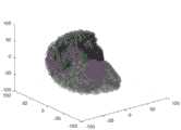
图6是最近迭代法点云匹配前仿真图Figure 6 is the simulation diagram before point cloud matching of the latest iteration method
图7是最近迭代法点云匹配后仿真图Figure 7 is the simulation diagram after point cloud matching by the latest iteration method
具体实施方式Detailed ways
本发明的目的在于提出了一种将基于逐帧识别生成原始点云的方法应用于多架小型四旋翼无人机协同编队飞行的平台设计方案。具体而言,就是结合分布式编队结构,使用室内动态捕捉系统进行逐帧识别生成原始点云来获取小型无人机编队的飞行轨迹和飞行状态,并配合带有前馈作用的串联PID控制器和人工势场法的轨迹规划方法提出了一套完整的室内多架小型四旋翼无人机协同编队飞行演示验证平台设计方案,解决了现有的室内多无人机编队飞行系统中,由于无人机体积较小,利用标记点的方法难以区分多台无人机的技术问题,提高了四旋翼无人机的协同编队飞行效果。The purpose of the present invention is to propose a platform design scheme that applies the method of generating original point clouds based on frame-by-frame recognition to the coordinated formation flight of multiple small quadrotor UAVs. Specifically, combined with the distributed formation structure, the indoor dynamic capture system is used for frame-by-frame identification to generate the original point cloud to obtain the flight trajectory and flight status of the small UAV formation, and the series PID controller with feedforward action is used. And the trajectory planning method of artificial potential field method proposes a complete set of indoor multiple small quadrotor UAV collaborative formation flight demonstration and verification platform design scheme, which solves the problem of existing indoor multi-UAV formation flight system, due to the lack of The man-machine is small in size, and it is difficult to distinguish the technical problems of multiple UAVs by using the method of marking points, which improves the coordinated formation flying effect of quadrotor UAVs.
本发明在实际编队飞行中可通过逐帧识别生成原始点云图像的方法获取无人机数据,配合带有前馈作用的串联PID控制器和人工势场法进行编队飞行,进而促进理论研究的发展。In the actual formation flight, the invention can obtain the UAV data through the method of generating the original point cloud image by frame-by-frame identification, and cooperate with the series PID controller with the feedforward action and the artificial potential field method to carry out the formation flight, thereby promoting the theoretical research. develop.
(一)总体架构设计方案(1) Overall architecture design scheme
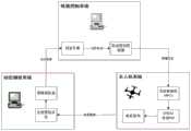
本发明总体架构如图1所示,其总体结构主要由室内动态捕捉系统、地面控制系统、多无人机系统组成,通过室内动态捕捉系统同时获取多架无人机的点云图像信息,通过地面控制系统实现对无人机的位姿信息和编队轨迹的求解,通过多无人机系统接收地面控制系统的控制指令实现室内多无人机编队飞行演示效果。同时,本发明在实际编队飞行中可通过逐帧识别生成原始点云图像的方法获取无人机数据,配合带有前馈作用的串联PID控制器和人工势场法进行编队飞行,进而促进理论研究的发展。The overall structure of the present invention is shown in Figure 1. The overall structure is mainly composed of an indoor dynamic capture system, a ground control system, and a multi-UAV system. The indoor dynamic capture system simultaneously acquires the point cloud image information of multiple UAVs, and through The ground control system realizes the solution of the position and attitude information and formation trajectory of the UAV, and the indoor multi-UAV formation flight demonstration effect is realized by receiving the control commands of the ground control system through the multi-UAV system. At the same time, in the actual formation flight, the present invention can obtain UAV data through the method of generating original point cloud images by frame-by-frame identification, and cooperate with the series PID controller with feedforward action and the artificial potential field method to perform formation flight, thereby promoting the theoretical development of research.
本系统采用Optitrack室内动态捕捉系统跟踪被反光球标记的无人机。选择室内动态捕捉系统的原因是它在定位方面的高性能:位置误差小于1毫米。与之相比,最先进的分散定位系统——超带宽无线电三角测量方法的位置误差大于10cm,对于本系统的小型无人机来说,误差过大。The system uses the Optitrack indoor dynamic capture system to track UAVs marked by reflective balls. The reason for choosing the indoor motion capture system is its high performance in positioning: the position error is less than 1 mm. In contrast, the state-of-the-art decentralized positioning system, the ultra-bandwidth radio triangulation method, has a position error of more than 10 cm, which is too large for the small UAV of this system.
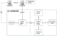
如图2所示,本系统使用的小型无人机自身主要由以下几个部分组成:主控制器为STM32F405,负责无人机状态估计计算、产生PWM波送至电机驱动;六轴陀螺仪MPU-9250,用于检测无人机自身局部的姿态变化;通信模块为nRF51,可发送或接收2.4GHz的无线电波,负责和上位机的通信。在无人机中部装有可拆卸的小型锂电池,电池可利用板载USB2.0接口直接充电,或者取下单独充电。底部和上部都有拓展口,可拓展led环形灯等等各种模块。电机的类型是小型的空心杯,共由四个空心杯和直径大约为7cm的4个旋翼组成,其中A型和B型旋翼各一对。改造无人机内部软件的方法是利用USB2.0通过对主控芯片STM32F4烧写固件以及控制程序。该机型体积小,适用于密集地层的室内飞行。由于其低惯性,它能在高速碰撞中幸存下来,对人类构成的风险也很小。As shown in Figure 2, the small drone used in this system is mainly composed of the following parts: the main controller is STM32F405, which is responsible for the estimation and calculation of the state of the drone, and generates PWM waves to send to the motor drive; six-axis gyroscope MPU -9250, used to detect the local attitude change of the drone; the communication module is nRF51, which can send or receive 2.4GHz radio waves, and is responsible for communication with the host computer. A detachable small lithium battery is installed in the middle of the drone. The battery can be directly charged using the onboard USB2.0 interface, or it can be removed and charged separately. There are expansion ports on the bottom and top, which can expand various modules such as LED ring lights. The type of motor is a small hollow cup, which consists of four hollow cups and four rotors with a diameter of about 7cm, of which the A-type and B-type rotors each have a pair. The method of transforming the internal software of the drone is to use USB2.0 to burn the firmware and control program to the main control chip STM32F4. This model is small in size and suitable for indoor flight in dense strata. Due to its low inertia, it can survive high-speed collisions and pose little risk to humans.
室内动态捕捉系统有一台PC和多台高速红外摄像头组成,PC上安装Optitrack软件,控制并接收室内动态捕捉系统所获取的无人机编队的数据,并通过以太网将数据传送给地面控制系统;地面控制系统为另一个PC,即无人机编队控制计算机,在该PC上运行Linux操作系统并运行各个功能模块,同时结合ROS操作系统的通信架构实现各个功能间的数据交互。The indoor dynamic capture system consists of a PC and multiple high-speed infrared cameras. The Optitrack software is installed on the PC to control and receive the data of the UAV formation acquired by the indoor dynamic capture system, and transmit the data to the ground control system through Ethernet; The ground control system is another PC, that is, the UAV formation control computer. The PC runs the Linux operating system and runs various functional modules. At the same time, the communication architecture of the ROS operating system is combined to realize the data interaction between the various functions.
室内小型四旋翼无人机编队演示验证平台工作原理为首先通过室内定位系统经过标定构建出室内三维坐标系,通过动态捕捉系统使用逐帧识别生成原始点云方法识别各个无人机,控制动态捕捉系统的PC通过以太网将无人机的数据发送给另一台PC,另一台PC上的各个模块根据数据计算出每架无人机当前的运动状态并计算出合理的飞行轨迹,再通过无线电广播设备将轨迹信息发送至无人机,无人机接收到定位信息和控制指令,根据系统时间和轨迹信息计算当前无人机的期望运动状态,无人机根据自身运动状态和期望运动状态,通过控制器控制算法驱使无人机按照轨迹飞行,最终实现无人机编队飞行。The working principle of the indoor small quadrotor UAV formation demonstration and verification platform is to first construct an indoor three-dimensional coordinate system through the calibration of the indoor positioning system, and then use the dynamic capture system to use frame-by-frame identification to generate the original point cloud method to identify each UAV and control the dynamic capture. The PC of the system sends the data of the drone to another PC through the Ethernet, and each module on the other PC calculates the current motion state of each drone according to the data and calculates a reasonable flight trajectory, and then passes The radio broadcasting equipment sends the trajectory information to the UAV, and the UAV receives the positioning information and control instructions, and calculates the desired motion state of the current UAV according to the system time and trajectory information, and the UAV according to its own motion state and desired motion state , through the controller control algorithm to drive the UAV to fly according to the trajectory, and finally realize the UAV formation flight.
(二)小型无人机识别设计方案(2) Small UAV Identification Design Scheme
本发明根据多台高速红外摄像机对无人机进行逐帧识别,并将每一帧图像生成原始的点云图。由于每台摄像机拍摄视角不同,对同一架无人机所得到的点云会有较大的差异,通过迭代最近点的点云匹配算法,通过空间变换将多张点云图像信息融合,以此来并行获取多台无人机在空间中的位姿信息。The invention performs frame-by-frame identification of the drone according to multiple high-speed infrared cameras, and generates an original point cloud image for each frame of images. Due to the different shooting angles of each camera, the point cloud obtained by the same UAV will be quite different. By iterating the point cloud matching algorithm of the nearest point, the information of multiple point cloud images is fused through spatial transformation, so as to To obtain the pose information of multiple UAVs in space in parallel.
如图3所示,3D点云图像的匹配详细步骤如下:As shown in Figure 3, the detailed steps of 3D point cloud image matching are as follows:
(1)假设待配准的点云集合为


(2)对于两个点集之间的相似度度量,用如下目标函数表示:(2) For the similarity measure between two point sets, it is expressed by the following objective function:

其中,R为旋转矩阵,T为平移矩阵,即姿态与位置的矩阵表示,
旋转矩阵R和平移矩阵T为:The rotation matrix R and translation matrix T are:

T=[q4 q5 q6]TT=[q4 q5 q6 ]T
(3)设点云的集合p′和X的中心为


得到平均值后,分别求出两个点云集合的协方差矩阵为:After obtaining the average value, the covariance matrices of the two point cloud sets are calculated as:

其中利用反对称矩阵:where antisymmetric matrices are used:

构建得到列向量:Build the resulting column vector:
Δ=[A23 A31 A12]TΔ=[A23 A31 A12 ]T
最终构建出以下目矩阵:Finally, the following project matrix is constructed:

其中tr(∑px)表示矩阵∑px的迹,即主对角线元素的总和,也就是特征值之和。where tr(∑px) represents the trace of the matrix ∑px, that is, the sum of the main diagonal elements, that is, the sum of the eigenvalues.
(4)代入数据后,对Q矩阵作特征值分解,求得最大的特征值以及对应的特征向量。此特征向量即为对应误差平方和最小时的四元数。将求得的四元数代入矩阵R中,即可求出旋转矩阵,平移矩阵T可通过两个点云集合的中心关系,平移得到。(4) After substituting the data, decompose the eigenvalue of the Q matrix to obtain the largest eigenvalue and the corresponding eigenvector. This eigenvector is the quaternion corresponding to the minimum sum of squared errors. The rotation matrix can be obtained by substituting the obtained quaternion into the matrix R, and the translation matrix T can be obtained by translation through the center relationship of the two point cloud sets.
(5)重复迭代以上4个步骤,直至求出的
(三)轨迹控制设计方案本发明所采用的轨迹控制方案主要包括如下几个步骤:(3) Design scheme of trajectory control The trajectory control scheme adopted by the present invention mainly includes the following steps:
步骤1:设计带有前馈作用的串联PID控制器Step 1: Design a series PID controller with feedforward action
本系统的控制器是非线性位置控制器,增加了位置和偏航误差的积分项。控制输入是当前状态(P,V,q,ωm)以及位置偏微分方程Pdes、速度偏微分方程Vdes、加速度偏微分方程
ep=pdes-p,ev=vdes-vep =pdes -p, ev =vdes -v
分别计算所需的力向量,如下所示:Calculate the required force vectors separately as follows:

其中Kp,Ki,Kv是正对角增益矩阵where Kp , Ki , Kv are positive diagonal gain matrices
期望的物体旋转矩阵Rdes是一个关于Fdes、ψdes的函数。方向误差计算如下The desired object rotation matrix Rdes is a function of Fdes , ψdes . The direction error is calculated as follows

其中R是是姿态四元数q的矩阵形式,(·)V是V算子映射S03→R3,where R is the matrix form of the attitude quaternion q, ( )V is the V operator map S03→R3 ,
然后用另一个PID控制器计算所需的矩:Then calculate the required torque with another PID controller:

正对角线增益矩阵K0,Km,Kω.一个简单的线性映射可以计算出Mdes和Fdes到z轴的投影所需要的平方向速度.Positive diagonal gain matrices K0 , Km , Kω . A simple linear mapping can calculate the required planar velocity for the projection of Mdes and Fdes to the z-axis.
Fdes中的位置误差积分补偿了由于不对称(x;y部分)导致的电池电压降(z部分)和质心不平衡。从Mdes中的姿态误差积分出发,只使用z分量,它可以补偿由于螺旋桨和发动机磨损不均造成的偏航误差。手工修整和零件更换可以补偿单一飞行器的这类问题,但在大型飞行器编队中是不可行的。The position error integration in Fdes compensates for the cell voltage drop (z part) and centroid imbalance due to the asymmetry (x;y part). Starting from the attitude error integral in Mdes , using only the z component, it compensates for the yaw error due to uneven wear on the propeller and engine. Manual trimming and parts replacement can compensate for such problems with a single aircraft, but are not feasible in large aircraft formations.
步骤2:基于人工势场法的无人机飞行轨迹规划Step 2: UAV flight trajectory planning based on artificial potential field method
人工势场法(APF)的基本思想是假想目标点对无人机存在引力作用,而障碍物对无人机存在斥力作用,无人机在两种力的共同作用下,靠近目标点并避开障碍物。The basic idea of artificial potential field method (APF) is that the imaginary target point has a gravitational effect on the UAV, while the obstacle has a repulsive force on the UAV. Under the combined action of the two forces, the UAV approaches the target point and avoids it. Open obstacles.
如图4所示,无人机与目标在m维空间中对应的两点之间的真实距离会对引力势场函数造成影响,而斥力势场函数则与该无人机与障碍物之间的欧几里得距离有关。引力势场函数及斥力势场函数如下所示:As shown in Figure 4, the real distance between the UAV and the target corresponding to two points in the m-dimensional space will affect the gravitational potential field function, while the repulsive potential field function is related to the distance between the UAV and the obstacle. is related to the Euclidean distance. The gravitational potential field function and the repulsive potential field function are as follows:


式中,p——无人机的具体位置;In the formula, p——the specific position of the UAV;
pdes——工作空间目标点的位置;pdes ——The position of the workspace target point;
p0b——工作空间障碍物的位置;p0b ——the position of the obstacle in the workspace;
ka——引力势场比例系数;ka ——the proportional coefficient of the gravitational potential field;
kr——斥力势场比例系数;kr — proportional coefficient of repulsive potential field;
ρ(p,pob)——无人机与障碍物在多维空间中的绝对距离;ρ(p, pob )——the absolute distance between the UAV and the obstacle in multi-dimensional space;
ρ0——单个障碍物影响的最大范围。ρ0 ——the maximum range of influence of a single obstacle.
考虑叠加性原理,对两个势场函数进行叠加运算可得到无人机的运动方向和位姿的合成势场函数,无人机所受矢量合力由引力和斥力合成。Considering the principle of superposition, the superposition operation of the two potential field functions can obtain the composite potential field function of the UAV's movement direction and pose, and the vector resultant force on the UAV is composed of gravitational and repulsive forces.
U(p)=Ua(p)+Ur(p)U(p)=Ua (p)+Ur (p)
F(p)=Fa(p)+Fr(p)F(p)=Fa (p)+Fr (p)
(四)具体实例分析(4) Analysis of specific examples
①小型四旋翼无人机:本实例使用Crazyflie2.0,斜对的电机轴之间长92毫米,带电池重27克。它包含一个32位,168兆赫的ARM微控制器与浮点单元,能够显着板载计算。软件和硬件都是开源的。Crazyflie通过Crazyradio PA与PC进行通信,Crazyradio PA是一个2.4GHz的USB无线电广播设备,可以以高达2兆比特/秒的速度传输32字节大小的数据包。①Small quad-rotor drone: Crazyflie 2.0 is used in this example, the length between the diagonally opposite motor shafts is 92 mm, and the weight with the battery is 27 grams. It contains a 32-bit, 168 MHz ARM microcontroller with a floating-point unit, capable of significant on-board computation. Both software and hardware are open source. Crazyflie communicates with the PC via the Crazyradio PA, a 2.4GHz USB radio broadcast device that can transmit 32-byte packets at speeds up to 2 Mbit/s.
②地面控制系统:本系统由一台台式机组成,处理器为因特尔酷睿i7-8700,运行内存为16G DDR4 2666MHz,主频为3.0GHz,显卡为GTX1060,主要作用是运行基于python的地面系统软件,进行点云匹配和轨迹规划的计算,并将期望位姿实时发送给无人机。②Ground control system: This system consists of a desktop computer, the processor is Intel Core i7-8700, the running memory is 16G DDR4 2666MHz, the main frequency is 3.0GHz, the graphics card is GTX1060, the main function is to run the ground based on python The system software performs point cloud matching and trajectory planning calculations, and sends the desired pose to the UAV in real time.
③室内动态捕捉系统:本系统由一台台式机组成,配置了i7-8700处理器,运行内存为8G DDR4 2666MHz,主频为3.0GHz,显卡为GTX1080ti,运行了动态捕捉系统上位机motive。主要作用是获取无人机编队的三维点云信息,并通过局域网发送至地面控制系统。③Indoor motion capture system: This system consists of a desktop computer equipped with i7-8700 processor, running memory of 8G DDR4 2666MHz, main frequency of 3.0GHz, graphics card of GTX1080ti, running the motion capture system host computer motive. The main function is to obtain the 3D point cloud information of the UAV formation and send it to the ground control system through the local area network.
④实验结果分析:室内飞行空间为4m×5m×3m的立方体。前期,本实例在室内进行了两架编队飞行控制实验。随着无人机数量的增加,由于地面反光,无人机编队出现局部发散的情况。为了消除反射光对原始点云的获取的影响,最终在实验室地面铺设了一层黑地毯,最终成功进行了五架无人机协同编队飞行,五架无人机按照规划好的轨迹,进行了平移和逆时针旋转后降落。④ Analysis of experimental results: The indoor flight space is a cube of 4m×5m×3m. In the early stage, this example carried out two formation flight control experiments indoors. With the increase of the number of UAVs, due to the reflection on the ground, the UAV formation appears to be partially divergent. In order to eliminate the influence of reflected light on the acquisition of the original point cloud, a black carpet was finally laid on the ground of the laboratory, and five UAVs were successfully carried out in a coordinated formation flight. The five UAVs flew according to the planned trajectory. Landing after panning and counterclockwise rotation.
Claims (6)
Translated fromChinese


Priority Applications (1)
| Application Number | Priority Date | Filing Date | Title |
|---|---|---|---|
| CN202010401363.1ACN111580554B (en) | 2020-05-13 | 2020-05-13 | Indoor unmanned aerial vehicle formation flying method based on frame-by-frame identification and generation of original point cloud |
Applications Claiming Priority (1)
| Application Number | Priority Date | Filing Date | Title |
|---|---|---|---|
| CN202010401363.1ACN111580554B (en) | 2020-05-13 | 2020-05-13 | Indoor unmanned aerial vehicle formation flying method based on frame-by-frame identification and generation of original point cloud |
Publications (2)
| Publication Number | Publication Date |
|---|---|
| CN111580554Atrue CN111580554A (en) | 2020-08-25 |
| CN111580554B CN111580554B (en) | 2022-09-09 |
Family
ID=72110877
Family Applications (1)
| Application Number | Title | Priority Date | Filing Date |
|---|---|---|---|
| CN202010401363.1AActiveCN111580554B (en) | 2020-05-13 | 2020-05-13 | Indoor unmanned aerial vehicle formation flying method based on frame-by-frame identification and generation of original point cloud |
Country Status (1)
| Country | Link |
|---|---|
| CN (1) | CN111580554B (en) |
Cited By (4)
| Publication number | Priority date | Publication date | Assignee | Title |
|---|---|---|---|---|
| CN113627445A (en)* | 2021-08-05 | 2021-11-09 | 福州大学 | Formation planning system and method for multi-unmanned aerial vehicle aerial media |
| CN114690796A (en)* | 2020-12-31 | 2022-07-01 | 烟台中飞海装科技有限公司 | Relative positioning system and method for distance measurement between unmanned aerial vehicles |
| CN115436895A (en)* | 2022-07-18 | 2022-12-06 | 南京航空航天大学 | Unmanned aerial vehicle group scale identification method based on multi-dimensional super-resolution analysis |
| CN115496839A (en)* | 2022-09-21 | 2022-12-20 | 一飞(海南)科技有限公司 | A UAV formation animation processing method, processing system and storage medium |
Citations (5)
| Publication number | Priority date | Publication date | Assignee | Title |
|---|---|---|---|---|
| CN107807661A (en)* | 2017-11-24 | 2018-03-16 | 天津大学 | Four rotor wing unmanned aerial vehicle formation demonstration and verification platforms and method in TRAJECTORY CONTROL room |
| CN109389056A (en)* | 2018-09-21 | 2019-02-26 | 北京航空航天大学 | A kind of track surrounding enviroment detection method of space base multi-angle of view collaboration |
| CN109709801A (en)* | 2018-12-11 | 2019-05-03 | 智灵飞(北京)科技有限公司 | A kind of indoor unmanned plane positioning system and method based on laser radar |
| CN109974707A (en)* | 2019-03-19 | 2019-07-05 | 重庆邮电大学 | A Visual Navigation Method for Indoor Mobile Robots Based on Improved Point Cloud Matching Algorithm |
| CN110930495A (en)* | 2019-11-22 | 2020-03-27 | 哈尔滨工业大学(深圳) | Multi-unmanned aerial vehicle cooperation-based ICP point cloud map fusion method, system, device and storage medium |
- 2020
- 2020-05-13CNCN202010401363.1Apatent/CN111580554B/enactiveActive
Patent Citations (5)
| Publication number | Priority date | Publication date | Assignee | Title |
|---|---|---|---|---|
| CN107807661A (en)* | 2017-11-24 | 2018-03-16 | 天津大学 | Four rotor wing unmanned aerial vehicle formation demonstration and verification platforms and method in TRAJECTORY CONTROL room |
| CN109389056A (en)* | 2018-09-21 | 2019-02-26 | 北京航空航天大学 | A kind of track surrounding enviroment detection method of space base multi-angle of view collaboration |
| CN109709801A (en)* | 2018-12-11 | 2019-05-03 | 智灵飞(北京)科技有限公司 | A kind of indoor unmanned plane positioning system and method based on laser radar |
| CN109974707A (en)* | 2019-03-19 | 2019-07-05 | 重庆邮电大学 | A Visual Navigation Method for Indoor Mobile Robots Based on Improved Point Cloud Matching Algorithm |
| CN110930495A (en)* | 2019-11-22 | 2020-03-27 | 哈尔滨工业大学(深圳) | Multi-unmanned aerial vehicle cooperation-based ICP point cloud map fusion method, system, device and storage medium |
Cited By (5)
| Publication number | Priority date | Publication date | Assignee | Title |
|---|---|---|---|---|
| CN114690796A (en)* | 2020-12-31 | 2022-07-01 | 烟台中飞海装科技有限公司 | Relative positioning system and method for distance measurement between unmanned aerial vehicles |
| CN113627445A (en)* | 2021-08-05 | 2021-11-09 | 福州大学 | Formation planning system and method for multi-unmanned aerial vehicle aerial media |
| CN113627445B (en)* | 2021-08-05 | 2023-08-15 | 福州大学 | Formation planning system and method for multi-unmanned aerial vehicle aerial media |
| CN115436895A (en)* | 2022-07-18 | 2022-12-06 | 南京航空航天大学 | Unmanned aerial vehicle group scale identification method based on multi-dimensional super-resolution analysis |
| CN115496839A (en)* | 2022-09-21 | 2022-12-20 | 一飞(海南)科技有限公司 | A UAV formation animation processing method, processing system and storage medium |
Also Published As
| Publication number | Publication date |
|---|---|
| CN111580554B (en) | 2022-09-09 |
Similar Documents
| Publication | Publication Date | Title |
|---|---|---|
| CN111580554B (en) | Indoor unmanned aerial vehicle formation flying method based on frame-by-frame identification and generation of original point cloud | |
| Giernacki et al. | Crazyflie 2.0 quadrotor as a platform for research and education in robotics and control engineering | |
| KR102010568B1 (en) | System having a plurality of Unmanned Aerial Vehicles and Real world 3 dimensional Space Search method using Swarm Intelligence | |
| CN107589752B (en) | Method and system for realizing cooperative formation of unmanned aerial vehicle and ground robot | |
| CN110825113B (en) | A Formation Keeping Method Applicable to Quadrotor UAV Swarm Flight | |
| Ghadiok et al. | On the design and development of attitude stabilization, vision-based navigation, and aerial gripping for a low-cost quadrotor | |
| CN104062977B (en) | Full-autonomous flight control method for quadrotor unmanned aerial vehicle based on vision SLAM | |
| CN205891228U (en) | Flying robot | |
| CN109895099B (en) | A visual servo grasping method of flying manipulator based on natural features | |
| CN106774389A (en) | A kind of four rotor wing unmanned aerial vehicles electricity tower method for inspecting based on motor learning | |
| Mohta et al. | Vision-based control of a quadrotor for perching on lines | |
| CN111596684A (en) | Fixed-wing unmanned aerial vehicle dense formation and anti-collision obstacle avoidance semi-physical simulation system and method | |
| CN110231828B (en) | Four-rotor unmanned aerial vehicle visual servo control method based on nonsingular rapid terminal sliding mode | |
| CN103365297A (en) | Optical flow-based four-rotor unmanned aerial vehicle flight control method | |
| CN103365295A (en) | DSP (Digital Signal Processor)-based quad-rotor unmanned aerial vehicle autonomous hover control system and method | |
| CN106155076B (en) | A stable flight control method for a multi-rotor unmanned aerial vehicle | |
| CN104460685A (en) | Control system for four-rotor aircraft and control method of control system | |
| CN115291536B (en) | Verification method of semi-physical simulation platform for UAV tracking ground targets based on vision | |
| Cao et al. | UAV path planning based on improved particle swarm algorithm | |
| CN105955067A (en) | Multi-satellite intelligent cluster control simulation system based on quadrotor unmanned planes, and simulation method using the same to implement | |
| Lin et al. | Development of an unmanned coaxial rotorcraft for the DARPA UAVForge challenge | |
| Fink et al. | Dynamic visual servoing for a quadrotor using a virtual camera | |
| CN108945536A (en) | A kind of spacecrafts rendezvous experiment porch based on rotor craft | |
| CN115857372A (en) | Control Simulation System of Distributed Multi-UAV Cluster Cooperative Space Search and Scheduling | |
| Chu et al. | Autonomous Landing System of a VTOL UAV on an Upward Docking Station Using Visual Servoing |
Legal Events
| Date | Code | Title | Description |
|---|---|---|---|
| PB01 | Publication | ||
| PB01 | Publication | ||
| SE01 | Entry into force of request for substantive examination | ||
| SE01 | Entry into force of request for substantive examination | ||
| GR01 | Patent grant | ||
| GR01 | Patent grant |