CN111580281B - Optical device - Google Patents
Optical deviceDownload PDFInfo
- Publication number
- CN111580281B CN111580281BCN201910116044.3ACN201910116044ACN111580281BCN 111580281 BCN111580281 BCN 111580281BCN 201910116044 ACN201910116044 ACN 201910116044ACN 111580281 BCN111580281 BCN 111580281B
- Authority
- CN
- China
- Prior art keywords
- light
- light source
- lens array
- spots
- vcsel
- Prior art date
- Legal status (The legal status is an assumption and is not a legal conclusion. Google has not performed a legal analysis and makes no representation as to the accuracy of the status listed.)
- Active
Links
- 230000003287optical effectEffects0.000titleclaimsabstractdescription61
- 239000000758substrateSubstances0.000claimsdescription11
- 238000010586diagramMethods0.000description8
- 238000004519manufacturing processMethods0.000description2
- 230000004075alterationEffects0.000description1
- 230000007423decreaseEffects0.000description1
- 238000005516engineering processMethods0.000description1
- 238000003384imaging methodMethods0.000description1
- 238000000034methodMethods0.000description1
- 238000006467substitution reactionMethods0.000description1
Images


Classifications
- G—PHYSICS
- G02—OPTICS
- G02B—OPTICAL ELEMENTS, SYSTEMS OR APPARATUS
- G02B27/00—Optical systems or apparatus not provided for by any of the groups G02B1/00 - G02B26/00, G02B30/00
- G02B27/09—Beam shaping, e.g. changing the cross-sectional area, not otherwise provided for
- G02B27/0916—Adapting the beam shape of a semiconductor light source such as a laser diode or an LED, e.g. for efficiently coupling into optical fibers
- G—PHYSICS
- G02—OPTICS
- G02B—OPTICAL ELEMENTS, SYSTEMS OR APPARATUS
- G02B27/00—Optical systems or apparatus not provided for by any of the groups G02B1/00 - G02B26/00, G02B30/00
- G02B27/09—Beam shaping, e.g. changing the cross-sectional area, not otherwise provided for
- G02B27/0938—Using specific optical elements
- G02B27/095—Refractive optical elements
- G02B27/0955—Lenses
- G02B27/0961—Lens arrays
Landscapes
- Physics & Mathematics (AREA)
- General Physics & Mathematics (AREA)
- Optics & Photonics (AREA)
- Semiconductor Lasers (AREA)
- Lenses (AREA)
- Optical Radar Systems And Details Thereof (AREA)
- Optical Head (AREA)
Abstract
Description
Translated fromChinese技术领域technical field
本公开实施例是有关于一种光学装置,且特别是有关于一种用以提供具有特定图案的结构光的光学装置。Embodiments of the present disclosure relate to an optical device, and more particularly, to an optical device for providing structured light with a specific pattern.
背景技术Background technique
结构光(structured light)是具有特定图案的光。结构光可被投影在一个或多个感兴趣的物体上。接着,被物体所反射的反射光由一个或多个成像感测器所感测,以产生用于立体图像匹配的三维图像。结构光的应用显著地增加,且相关的技术已被广泛的研究与开发。Structured light is light with a specific pattern. Structured light can be projected on one or more objects of interest. The reflected light reflected by the object is then sensed by one or more imaging sensors to generate a three-dimensional image for stereoscopic image matching. The application of structured light has increased significantly, and related technologies have been extensively researched and developed.
一种已知的结构光产生单元包含多点(multi-dots)发射光源、投影透镜与衍射式光学元件(diffractive optical element,DOE),然而,由于后聚焦(back-focusing)与投影透镜的长度较长,这种已知的结构光产生单元的空间利用率较差。另一种已知的结构光产生单元包含光源、硬质光罩(hard mask)与投影透镜,然而,硬质光罩会遮挡部分从光源所发射的光,因此这种已知的结构光产生单元的效率较差。又另一种已知的结构光产生单元包含边射型激光(edge emitting laser)、准直透镜与衍射式光学元件,然而,衍射式光学元件的制作控制不易,因此衍射式光学元件存在着零序功率(zero order power)的问题,对人眼较易有安全疑虑。再另一种已知的结构光产生单元包含多点发射光源、衍射透镜与衍射式光学元件,然而,将衍射透镜与衍射式光学元件做在同一元件内的制作相当严苛,使得这种已知的结构光产生单元的衍射效率较差。A known structured light generating unit includes a multi-dots emitting light source, a projection lens and a diffractive optical element (DOE). However, due to the length of the back-focusing and projection lenses Longer, the known structured light generating unit has poor space utilization. Another known structured light generating unit includes a light source, a hard mask and a projection lens. However, the hard mask blocks part of the light emitted from the light source, so this known structured light generating unit The unit is less efficient. Yet another known structured light generating unit includes an edge emitting laser, a collimating lens and a diffractive optical element. However, the manufacturing and control of the diffractive optical element is not easy, so the diffractive optical element has zero problems. The problem of zero order power makes it easier for the human eye to have safety concerns. Yet another known structured light generating unit includes a multi-point emission light source, a diffractive lens and a diffractive optical element. The diffraction efficiency of the known structured light generating unit is poor.
发明内容SUMMARY OF THE INVENTION
本公开的目的在于提出一种光学装置,包含垂直共振腔面射型激光(Vertical-Cavity Surface-Emitting Laser,VCSEL)光源与透镜阵列。垂直共振腔面射型激光光源用以发射具有至少一光点的光。透镜阵列用以接收从垂直共振腔面射型激光光源所发射来的光,从而投影结构光(structured light)。结构光包含具有数个光点的点图案。多个凸透镜沿着透镜阵列的第一表面设置,且凸透镜用以产生点图案的光点。The purpose of the present disclosure is to provide an optical device, which includes a Vertical-Cavity Surface-Emitting Laser (VCSEL) light source and a lens array. The vertical resonant cavity surface-emitting laser light source is used for emitting light with at least one light spot. The lens array is used to receive the light emitted from the vertical resonant cavity surface-emitting laser light source, so as to project structured light. Structured light consists of a dot pattern with several light spots. A plurality of convex lenses are arranged along the first surface of the lens array, and the convex lenses are used to generate light spots of a dot pattern.
在一些实施例中,其中多个凹透镜沿着透镜阵列的第二表面设置,且第一表面与第二表面彼此相对;其中第一表面相应于透镜阵列的入光面,且第二表面相应于透镜阵列的出光面;其中凹透镜用以增加光学装置的视野(field of view,FOV)。In some embodiments, the plurality of concave lenses are disposed along the second surface of the lens array, and the first surface and the second surface are opposite to each other; wherein the first surface corresponds to the light incident surface of the lens array, and the second surface corresponds to The light-emitting surface of the lens array; the concave lens is used to increase the field of view (FOV) of the optical device.
在一些实施例中,其中根据垂直共振腔面射型激光光源的发散角(divergenceangle)、垂直共振腔面射型激光光源的节距(pitch)、垂直共振腔面射型激光光源的光点的数量、每个凸透镜的节距、每个凸透镜的球高、透镜阵列的基板厚度以及介于垂直共振腔面射型激光光源与透镜阵列之间的后焦距(back focal length,BFL)的至少一者,来决定结构光的点图案。In some embodiments, wherein according to the divergence angle of the vertical resonant cavity surface emitting laser light source, the pitch of the vertical resonant cavity surface emitting laser light source, the light spot of the vertical resonant cavity surface emitting laser light source At least one of the number, the pitch of each convex lens, the spherical height of each convex lens, the substrate thickness of the lens array, and the back focal length (BFL) between the vertical resonant cavity surface-emitting laser light source and the lens array to determine the dot pattern of structured light.
在一些实施例中,其中根据垂直共振腔面射型激光光源的发散角、垂直共振腔面射型激光光源的节距、垂直共振腔面射型激光光源的光点的数量、每个凹透镜的节距、每个凹透镜的球高、每个凸透镜的节距、每个凸透镜的球高、透镜阵列的基板厚度以及介于垂直共振腔面射型激光光源与透镜阵列之间的后焦距的至少一者,来决定结构光的点图案。In some embodiments, wherein according to the divergence angle of the vertical resonant cavity surface emitting laser light source, the pitch of the vertical resonant cavity surface emitting laser light source, the number of light spots of the vertical resonant cavity surface emitting laser light source, the At least one of the pitch, the spherical height of each concave lens, the pitch of each convex lens, the spherical height of each convex lens, the substrate thickness of the lens array, and the back focal length between the vertical cavity surface-emitting laser light source and the lens array One, to determine the dot pattern of structured light.
在一些实施例中,其中根据每个凸透镜的节距来设计垂直共振腔面射型激光光源的光点的排列方式,从而决定结构光的点图案的光点的排列方式或增加结构光的点图案的光点的数量。In some embodiments, the arrangement of the light spots of the vertical resonant cavity surface-emitting laser light source is designed according to the pitch of each convex lens, so as to determine the arrangement of the light spots of the dot pattern of structured light or increase the dots of structured light The number of light spots in the pattern.
本公开的目的在于另提出一种光学装置,包含垂直共振腔面射型激光光源、透镜阵列与衍射式光学元件(diffractive optical element,DOE)。垂直共振腔面射型激光光源用以发射具有至少一光点的光。透镜阵列用以接收从垂直共振腔面射型激光光源所发射来的光,从而提供具有数个光点的图案光(patterned light)。衍射式光学元件用以扇出(fan out)图案光,从而投影结构光。结构光包含具有数个光点的点图案。其中衍射式光学元件用以增加光学装置的视野且用以产生点图案的光点。其中点图案的光点的数量大于图案光的光点的数量。The purpose of the present disclosure is to provide another optical device, which includes a vertical resonant cavity surface-emitting laser light source, a lens array, and a diffractive optical element (DOE). The vertical resonant cavity surface-emitting laser light source is used for emitting light with at least one light spot. The lens array is used to receive the light emitted from the vertical resonant cavity surface-emitting laser light source, thereby providing patterned light with several light spots. Diffractive optical elements are used to fan out patterned light to project structured light. Structured light consists of a dot pattern with several light spots. The diffractive optical element is used to increase the field of view of the optical device and to generate light spots of a dot pattern. wherein the number of light spots of the dot pattern is greater than the number of light spots of the pattern light.
在一些实施例中,其中多个凸透镜沿着透镜阵列的第一表面设置,且凸透镜用以产生图案光的光点。In some embodiments, a plurality of convex lenses are disposed along the first surface of the lens array, and the convex lenses are used to generate light spots of pattern light.
在一些实施例中,其中多个凹透镜沿着透镜阵列的第二表面设置,且第一表面与第二表面彼此相对。其中第一表面相应于透镜阵列的入光面,且第二表面相应于透镜阵列的出光面。其中凹透镜用以增加光学装置的视野。In some embodiments, the plurality of concave lenses are disposed along the second surface of the lens array, and the first surface and the second surface are opposite to each other. The first surface corresponds to the light incident surface of the lens array, and the second surface corresponds to the light exit surface of the lens array. The concave lens is used to increase the field of view of the optical device.
在一些实施例中,其中根据垂直共振腔面射型激光光源的发散角、垂直共振腔面射型激光光源的节距、垂直共振腔面射型激光光源的光点的数量、每个凸透镜的节距、每个凸透镜的球高、透镜阵列的基板厚度以及介于垂直共振腔面射型激光光源与透镜阵列之间的后焦距的至少一者,来决定结构光的点图案。In some embodiments, wherein according to the divergence angle of the vertical resonant cavity surface emitting type laser light source, the pitch of the vertical resonant cavity surface emitting type laser light source, the number of light spots of the vertical resonant cavity surface emitting type laser light source, the At least one of the pitch, the spherical height of each convex lens, the substrate thickness of the lens array, and the back focal length between the vertical resonant cavity surface-emitting laser light source and the lens array determines the dot pattern of the structured light.
在一些实施例中,其中根据垂直共振腔面射型激光光源的发散角、垂直共振腔面射型激光光源的节距、垂直共振腔面射型激光光源的光点的数量、每个凸透镜的节距、每个凸透镜的球高、每个凹透镜的节距、每个凹透镜的球高、透镜阵列的基板厚度以及介于垂直共振腔面射型激光光源与透镜阵列之间的后焦距的至少一者,来决定结构光的点图案。In some embodiments, wherein according to the divergence angle of the vertical resonant cavity surface emitting type laser light source, the pitch of the vertical resonant cavity surface emitting type laser light source, the number of light spots of the vertical resonant cavity surface emitting type laser light source, the At least the pitch, the spherical height of each convex lens, the pitch of each concave lens, the spherical height of each concave lens, the substrate thickness of the lens array, and the back focal length between the vertical resonant cavity surface-emitting laser light source and the lens array One, to determine the dot pattern of structured light.
在一些实施例中,其中根据每个凸透镜的节距来设计垂直共振腔面射型激光光源的光点的排列方式,从而决定结构光的点图案的光点的排列方式或增加结构光的点图案的光点的数量。In some embodiments, the arrangement of the light spots of the vertical resonant cavity surface-emitting laser light source is designed according to the pitch of each convex lens, so as to determine the arrangement of the light spots of the dot pattern of structured light or increase the dots of structured light The number of light spots in the pattern.
在一些实施例中,其中衍射式光学元件的结构被设计为用以散射图案光,从而决定结构光的点图案的光点的排列方式或增加结构光的点图案的光点的数量。In some embodiments, the structure of the diffractive optical element is designed to scatter the patterned light, thereby determining the arrangement of the light spots of the structured light dot pattern or increasing the number of light spots of the structured light dot pattern.
附图说明Description of drawings
通过阅读实施例的以下详细描述,且参考如下附图,可以更完整地理解本公开。A more complete understanding of the present disclosure may be obtained by reading the following detailed description of the embodiments, with reference to the following drawings.
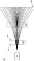
图1是根据本公开的第一实施例的光学装置的示意图。FIG. 1 is a schematic diagram of an optical device according to a first embodiment of the present disclosure.
图2是根据本公开的第一实施例的光学装置的垂直共振腔面射型激光光源的光点的一种排列方式的示意图。2 is a schematic diagram of an arrangement of light spots of the vertical resonant cavity surface-emitting laser light source of the optical device according to the first embodiment of the present disclosure.
图3是根据本公开的第一实施例的光学装置的垂直共振腔面射型激光光源的光点的另一种排列方式的示意图。3 is a schematic diagram of another arrangement of light spots of the vertical resonant cavity surface-emitting laser light source of the optical device according to the first embodiment of the present disclosure.
图4是根据本公开的第二实施例的光学装置的示意图。4 is a schematic diagram of an optical device according to a second embodiment of the present disclosure.
【附图标记说明】[Description of reference numerals]
1:第一组光点1: The first group of light spots
2:第二组光点2: The second group of light spots
3:第三组光点3: The third group of light spots
100、200:光学装置100, 200: Optical device
120、220:垂直共振腔面射型激光光源120, 220: Vertical resonant cavity surface-emitting laser light source
140、240:透镜阵列140, 240: lens array
142、242:入光面142, 242: light incident surface
144、244:出光面144, 244: light-emitting surface
180、280:平面180, 280: Flat
260:衍射式光学元件260: Diffractive Optics
d、x12、y12、x13、y13:距离d, x12, y12, x13, y13: distance
具体实施方式Detailed ways
下文举实施例配合附图作详细说明,但所提供的实施例并非用以限制本发明所涵盖的范围,而结构运行的描述非用以限制其执行的顺序,任何由元件重新组合的结构,所产生具有均等功效的装置,皆为本发明所涵盖的范围。此外,附图仅以说明为目的,并未依照原尺寸作图。The following examples are described in detail with the accompanying drawings, but the provided examples are not used to limit the scope of the present invention, and the description of the structure operation is not used to limit the order of its execution. Any structure that is recombined by elements, The resulting devices with equal efficacy are all within the scope of the present invention. In addition, the drawings are for illustrative purposes only, and are not drawn in full scale.
图1是根据本公开的第一实施例的光学装置100的示意图。光学装置100包含垂直共振腔面射型激光(Vertical-Cavity Surface-Emitting Laser,VCSEL)光源120与透镜阵列140。垂直共振腔面射型激光光源120用以朝向透镜阵列140发射光。在本公开的第一实施例中,垂直共振腔面射型激光光源120可为单点光源或多点光源,例如具有1x1个光点、3x3个光点或9x9个光点的光源。FIG. 1 is a schematic diagram of an
透镜阵列140用以接收从垂直共振腔面射型激光光源120所发射来的光,从而投影结构光(structured light)于平面180上。结构光包含用于特定目的(例如三维(3D)感测或立体图像匹配)的具有数个光点的点图案。结构光的点图案的光点的数量多于垂直共振腔面射型激光光源120的光点的数量。透镜阵列140具有彼此相对的两个表面,即入光面142与出光面144。入光面142比出光面144更靠近垂直共振腔面射型激光光源120。The
多个凹透镜沿着透镜阵列140的入光面142设置,且多个凸透镜沿着透镜阵列140的出光面144设置。然而,本公开的第一实施例不限于此。举例来说,入光面142可为平坦的表面且多个凸透镜沿着透镜阵列140的出光面144设置。举另一例来说,多个凸透镜沿着透镜阵列140的入光面142设置且出光面144可为平坦的表面。The plurality of concave lenses are arranged along the
应注意的是,凸透镜用以产生结构光的点图案的多个光点。应注意的是,凹透镜用以增加光学装置100的视野(field of view,FOV)。It should be noted that the convex lens is used to generate a plurality of light spots of the dot pattern of structured light. It should be noted that the concave lens is used to increase the field of view (FOV) of the
在本公开的第一实施例中,当透镜阵列140具有凹透镜与凸透镜分别沿着透镜阵列140的两个相对表面设置时,透镜阵列140所投影的结构光的点图案根据垂直共振腔面射型激光光源120的发散角(divergence angle)、垂直共振腔面射型激光光源120的节距(pitch)、垂直共振腔面射型激光光源120的光点的数量、每个凹透镜的节距、每个凹透镜的球高、每个凸透镜的节距、每个凸透镜的球高、透镜阵列140的基板厚度、介于垂直共振腔面射型激光光源120与透镜阵列140之间的后焦距(back focal length,BFL)、或其组合来决定。举例来说,当介于垂直共振腔面射型激光光源120与透镜阵列140之间的后焦距减少时,光学装置100的视野(field of view,FOV)相应地增加,但结构光的点图案的光点的数量相应地减少。In the first embodiment of the present disclosure, when the
在本公开的第一实施例中,当透镜阵列140具有一个平坦的表面与一个非平坦表面,其中非平坦表面具有凸透镜分别沿着该非平坦表面设置时,透镜阵列140所投影的结构光的点图案根据垂直共振腔面射型激光光源120的发散角、垂直共振腔面射型激光光源120的节距、垂直共振腔面射型激光光源120的光点的数量、每个凸透镜的节距、每个凸透镜的球高、透镜阵列140的基板厚度、介于垂直共振腔面射型激光光源120与透镜阵列140之间的后焦距(back focal length,BFL)、或其组合来决定。举例来说,当垂直共振腔面射型激光光源120的发散角增加时,光学装置100的视野(field of view,FOV)相应地增加,且结构光的点图案的光点的数量相应地增加。In the first embodiment of the present disclosure, when the
在本公开的第一实施例中,垂直共振腔面射型激光光源120的光点的排列方式被设计,以决定结构光的点图案的光点的排列方式或增加结构光的点图案的光点的数量。应注意的是,垂直共振腔面射型激光光源120的光点的排列方式根据透镜阵列140的每个凸透镜的节距来设计。In the first embodiment of the present disclosure, the arrangement of the light spots of the vertical resonant cavity surface-emitting
图2是根据本公开的第一实施例的光学装置100的垂直共振腔面射型激光光源120的光点的一种排列方式的示意图。垂直共振腔面射型激光光源120包含第一组光点、第二组光点与第三组光点,其中第一组光点即图2中以符号1圈起所标示者;第二组光点即图2中以符号2圈起所标示者;第三组光点即图2中以符号3圈起所标示者。应注意的是,距离d为透镜阵列140的每个凸透镜的节距。如图2所示,距离d+x12代表第一组光点与第二组光点之间的最近的水平间距,距离y12代表第一组光点与第二组光点之间的最近的垂直间距,距离x13代表第一组光点与第三组光点之间的最近的水平间距,距离d+y13代表第一组光点与第三组光点之间的最近的垂直间距。2 is a schematic diagram of an arrangement of light spots of the vertical resonant cavity surface-emitting
图3是根据本公开的第一实施例的光学装置100的垂直共振腔面射型激光光源120的光点的另一种排列方式的示意图。应注意的是,距离d为透镜阵列140的每个凸透镜的节距。如图3所示,距离x12代表第一组光点与第二组光点的其中两个光点之间的最近的水平间距,距离y12代表第一组光点与第二组光点的其中两个光点之间的最近的垂直间距,距离x13代表第一组光点与第三组光点的其中两个光点之间的最近的水平间距,距离y13代表第一组光点与第三组光点的其中两个光点之间的最近的垂直间距。应注意的是,如图2与图3所示的垂直共振腔面射型激光光源120的光点的排列方式的设计是为了增加结构光的点图案的不规则性,从而降低辨识特定物体的困难度。3 is a schematic diagram of another arrangement of light spots of the vertical resonant cavity surface-emitting
图4是根据本公开的第二实施例的光学装置200的示意图。光学装置200包含垂直共振腔面射型激光光源220、透镜阵列240与衍射式光学元件(diffractive opticalelement,DOE)260。垂直共振腔面射型激光光源220用以朝向透镜阵列240发射光。在本公开的第二实施例中,垂直共振腔面射型激光光源220可为单点光源或多点光源,例如具有1x1个光点、3x3个光点或9x9个光点的光源。FIG. 4 is a schematic diagram of an
透镜阵列240用以接收从垂直共振腔面射型激光光源220所发射来的光,从而投影具有数个光点的图案光(patterned light)。图案光的光点的数量多于垂直共振腔面射型激光光源220的光点的数量。衍射式光学元件260用以扇出(fan out)图案光,从而投影结构光于平面280上。结构光包含用于特定目的(例如三维(3D)感测或立体图像匹配)的具有数个光点的点图案。结构光的点图案的光点的数量大于图案光的光点的数量。透镜阵列240具有彼此相对的两个表面,即入光面242与出光面244。入光面242比出光面244更靠近垂直共振腔面射型激光光源220。The
多个凹透镜沿着透镜阵列240的入光面242设置,且多个凸透镜沿着透镜阵列240的出光面244设置。然而,本公开的第二实施例不限于此。举例来说,入光面242可为平坦的表面且多个凸透镜沿着透镜阵列240的出光面244设置。举另一例来说,多个凸透镜沿着透镜阵列240的入光面242设置且出光面244可为平坦的表面。The plurality of concave lenses are arranged along the
应注意的是,凸透镜用以产生结构光的点图案的多个光点。应注意的是,凹透镜用以增加光学装置100的视野(field of view,FOV)。应注意的是,衍射式光学元件260用以增加光学装置的视野且用以产生结构光的点图案的光点。It should be noted that the convex lens is used to generate a plurality of light spots of the dot pattern of structured light. It should be noted that the concave lens is used to increase the field of view (FOV) of the
在本公开的第二实施例中,由衍射式光学元件260所投影的结构光的点图案根据垂直共振腔面射型激光光源220的发散角、垂直共振腔面射型激光光源220的节距、垂直共振腔面射型激光光源220的光点的数量、每个凹透镜的节距、每个凹透镜的球高、每个凸透镜的节距、每个凸透镜的球高、透镜阵列240的基板厚度、介于垂直共振腔面射型激光光源220与透镜阵列240之间的后焦距、或其组合来决定。In the second embodiment of the present disclosure, the point pattern of the structured light projected by the diffractive
在本公开的第二实施例中,根据透镜阵列240的每个凸透镜的节距来设计垂直共振腔面射型激光光源220的光点的排列方式,以决定结构光的点图案的光点的排列方式或增加结构光的点图案的光点的数量。In the second embodiment of the present disclosure, the arrangement of the light spots of the vertical resonant cavity surface-emitting
在本公开的第二实施例中,衍射式光学元件260的结构被设计为用以散射图案光,从而决定结构光的点图案的光点的排列方式或增加结构光的点图案的光点的数量。举例来说,衍射式光学元件260可提供图案光的散射,以产生不同的衍射阶数(diffractionorders),从而增加结构光的点图案的光点的数量。具体而言,衍射式光学元件260可增加结构光的点图案的光点的密度。In the second embodiment of the present disclosure, the structure of the diffractive
综合上述,本公开提出一种光学装置包含垂直共振腔面射型激光光源与透镜阵列,本公开还提出一种光学装置包含垂直共振腔面射型激光光源、透镜阵列与衍射式光学元件。本公开所提出的光学装置用以提供包含数个光点的结构光。本公开所提出的光学装置使用透镜阵列,从而具有较佳的空间利用率。本公开所提出的光学装置使用透镜阵列与衍射式光学元件,从而具有较低的能量损失。In view of the above, the present disclosure proposes an optical device including a vertical resonant cavity surface-emitting laser light source and a lens array, and the present disclosure also provides an optical device including a vertical resonant cavity surface-emitting laser light source, a lens array and a diffractive optical element. The optical device proposed in the present disclosure is used to provide structured light including several light spots. The optical device proposed in the present disclosure uses a lens array, thereby having better space utilization. The optical device proposed in the present disclosure uses a lens array and diffractive optical elements, thereby having lower energy loss.
以上概述了数个实施例的特征,因此所属领域技术人员可以更了解本公开的态样。所属领域技术人员应了解到,其可轻易地把本公开当作基础来设计或修改其它的制作与结构,借此实现和在此所介绍的这些实施例相同的目标及/或达到相同的优点。所属领域技术人员也应可明白,这些等效的构型并未脱离本公开的精神与范围,并且他们可以在不脱离本公开精神与范围的前提下做各种的改变、替换与变动。The foregoing has outlined the features of several embodiments so that those skilled in the art may better understand aspects of the present disclosure. Those skilled in the art should appreciate that they may readily use the present disclosure as a basis for designing or modifying other fabrications and structures, thereby achieving the same objectives and/or achieving the same advantages as the embodiments described herein . It should also be understood by those skilled in the art that these equivalent configurations do not depart from the spirit and scope of the present disclosure, and that they can make various changes, substitutions and alterations without departing from the spirit and scope of the present disclosure.
Claims (7)
Priority Applications (1)
| Application Number | Priority Date | Filing Date | Title |
|---|---|---|---|
| CN201910116044.3ACN111580281B (en) | 2019-02-15 | 2019-02-15 | Optical device |
Applications Claiming Priority (1)
| Application Number | Priority Date | Filing Date | Title |
|---|---|---|---|
| CN201910116044.3ACN111580281B (en) | 2019-02-15 | 2019-02-15 | Optical device |
Publications (2)
| Publication Number | Publication Date |
|---|---|
| CN111580281A CN111580281A (en) | 2020-08-25 |
| CN111580281Btrue CN111580281B (en) | 2022-08-23 |
Family
ID=72114783
Family Applications (1)
| Application Number | Title | Priority Date | Filing Date |
|---|---|---|---|
| CN201910116044.3AActiveCN111580281B (en) | 2019-02-15 | 2019-02-15 | Optical device |
Country Status (1)
| Country | Link |
|---|---|
| CN (1) | CN111580281B (en) |
Citations (2)
| Publication number | Priority date | Publication date | Assignee | Title |
|---|---|---|---|---|
| CN106569382A (en)* | 2016-10-26 | 2017-04-19 | 深圳奥比中光科技有限公司 | Laser projector and depth camera thereof |
| CN106990660A (en)* | 2017-05-09 | 2017-07-28 | 深圳奥比中光科技有限公司 | Structured light projection module |
Family Cites Families (7)
| Publication number | Priority date | Publication date | Assignee | Title |
|---|---|---|---|---|
| DE112013006324T5 (en)* | 2012-12-31 | 2015-10-15 | Iee International Electronics & Engineering S.A. | An optical system for generating a structured light field from a series of light sources through a refractive or reflective light structuring element |
| CN103412406B (en)* | 2013-07-30 | 2015-12-09 | 中国科学院半导体研究所 | A kind of red light semiconductor area array light source device for laser display |
| US20150176977A1 (en)* | 2013-12-20 | 2015-06-25 | Lemoptix Sa | Methods and devices for determining position or distance |
| US20170074490A1 (en)* | 2014-03-04 | 2017-03-16 | Philips Lighting Holding B.V. | Dual-mode lighting fixture |
| CN106990548A (en)* | 2017-05-09 | 2017-07-28 | 深圳奥比中光科技有限公司 | Array laser projection arrangement and depth camera |
| CN108594454B (en)* | 2018-03-23 | 2019-12-13 | 深圳奥比中光科技有限公司 | Structured light projection module and depth camera |
| CN208297850U (en)* | 2018-05-09 | 2018-12-28 | 深圳阜时科技有限公司 | A kind of light source module group, image acquiring device, identity recognition device and electronic equipment |
- 2019
- 2019-02-15CNCN201910116044.3Apatent/CN111580281B/enactiveActive
Patent Citations (2)
| Publication number | Priority date | Publication date | Assignee | Title |
|---|---|---|---|---|
| CN106569382A (en)* | 2016-10-26 | 2017-04-19 | 深圳奥比中光科技有限公司 | Laser projector and depth camera thereof |
| CN106990660A (en)* | 2017-05-09 | 2017-07-28 | 深圳奥比中光科技有限公司 | Structured light projection module |
Also Published As
| Publication number | Publication date |
|---|---|
| CN111580281A (en) | 2020-08-25 |
Similar Documents
| Publication | Publication Date | Title |
|---|---|---|
| CN110031933B (en) | Light projection method and device | |
| US9400177B2 (en) | Pattern projector | |
| KR102439748B1 (en) | Optical elements and optical systems | |
| CN107703641B (en) | structured light projection module and depth camera | |
| JP2018514780A (en) | Distance sensor | |
| WO2020015542A1 (en) | Light projection method and apparatus | |
| CN114616484B (en) | Light source, sensor and method for illuminating a scene | |
| WO2020015540A1 (en) | Light projection method and apparatus | |
| CN112505983B (en) | Microprism optical element for realizing laser dot matrix and projection module | |
| CN116224607B (en) | Structured light projector and 3D structured light module | |
| US11137246B2 (en) | Optical device | |
| JP7488652B2 (en) | Diffractive optical element, light irradiation device, and method for reading irradiation pattern | |
| JP5361903B2 (en) | Optoelectronic device and image recording device | |
| CN111580281B (en) | Optical device | |
| WO2015156120A1 (en) | Optical element | |
| CN111610534B (en) | Imaging device and imaging method | |
| TWI728307B (en) | Optical device | |
| US8547642B2 (en) | Multi-beam, high efficiency diffractive optics system formed in a single substrate | |
| TWI719383B (en) | Multi-image projector and electronic device having multi-image projector | |
| JP2023522717A (en) | Diffractive optical element with collimator function | |
| JP7448272B2 (en) | Optical elements and optical system devices using the same | |
| CN211878295U (en) | A surface light source projection module, depth camera and electronic device | |
| CN115808837A (en) | projection device | |
| JP2024026011A (en) | Optical system device and optical element manufacturing method | |
| JP2016035548A (en) | Diffraction pattern projection optical system |
Legal Events
| Date | Code | Title | Description |
|---|---|---|---|
| PB01 | Publication | ||
| PB01 | Publication | ||
| SE01 | Entry into force of request for substantive examination | ||
| SE01 | Entry into force of request for substantive examination | ||
| GR01 | Patent grant | ||
| GR01 | Patent grant |