CN111580105A - Self-adaptive processing method for terahertz radar high-resolution imaging - Google Patents
Self-adaptive processing method for terahertz radar high-resolution imagingDownload PDFInfo
- Publication number
- CN111580105A CN111580105ACN202010488574.3ACN202010488574ACN111580105ACN 111580105 ACN111580105 ACN 111580105ACN 202010488574 ACN202010488574 ACN 202010488574ACN 111580105 ACN111580105 ACN 111580105A
- Authority
- CN
- China
- Prior art keywords
- points
- scattering
- point
- image
- threshold
- Prior art date
- Legal status (The legal status is an assumption and is not a legal conclusion. Google has not performed a legal analysis and makes no representation as to the accuracy of the status listed.)
- Granted
Links
Images


Classifications
- G—PHYSICS
- G01—MEASURING; TESTING
- G01S—RADIO DIRECTION-FINDING; RADIO NAVIGATION; DETERMINING DISTANCE OR VELOCITY BY USE OF RADIO WAVES; LOCATING OR PRESENCE-DETECTING BY USE OF THE REFLECTION OR RERADIATION OF RADIO WAVES; ANALOGOUS ARRANGEMENTS USING OTHER WAVES
- G01S13/00—Systems using the reflection or reradiation of radio waves, e.g. radar systems; Analogous systems using reflection or reradiation of waves whose nature or wavelength is irrelevant or unspecified
- G01S13/88—Radar or analogous systems specially adapted for specific applications
- G01S13/89—Radar or analogous systems specially adapted for specific applications for mapping or imaging
- G01S13/90—Radar or analogous systems specially adapted for specific applications for mapping or imaging using synthetic aperture techniques, e.g. synthetic aperture radar [SAR] techniques
- G01S13/904—SAR modes
- G01S13/9088—Circular SAR [CSAR, C-SAR]
- G—PHYSICS
- G01—MEASURING; TESTING
- G01S—RADIO DIRECTION-FINDING; RADIO NAVIGATION; DETERMINING DISTANCE OR VELOCITY BY USE OF RADIO WAVES; LOCATING OR PRESENCE-DETECTING BY USE OF THE REFLECTION OR RERADIATION OF RADIO WAVES; ANALOGOUS ARRANGEMENTS USING OTHER WAVES
- G01S13/00—Systems using the reflection or reradiation of radio waves, e.g. radar systems; Analogous systems using reflection or reradiation of waves whose nature or wavelength is irrelevant or unspecified
- G01S13/88—Radar or analogous systems specially adapted for specific applications
- G01S13/89—Radar or analogous systems specially adapted for specific applications for mapping or imaging
- G01S13/90—Radar or analogous systems specially adapted for specific applications for mapping or imaging using synthetic aperture techniques, e.g. synthetic aperture radar [SAR] techniques
- G01S13/9094—Theoretical aspects
- G—PHYSICS
- G01—MEASURING; TESTING
- G01S—RADIO DIRECTION-FINDING; RADIO NAVIGATION; DETERMINING DISTANCE OR VELOCITY BY USE OF RADIO WAVES; LOCATING OR PRESENCE-DETECTING BY USE OF THE REFLECTION OR RERADIATION OF RADIO WAVES; ANALOGOUS ARRANGEMENTS USING OTHER WAVES
- G01S7/00—Details of systems according to groups G01S13/00, G01S15/00, G01S17/00
- G01S7/02—Details of systems according to groups G01S13/00, G01S15/00, G01S17/00 of systems according to group G01S13/00
- G01S7/41—Details of systems according to groups G01S13/00, G01S15/00, G01S17/00 of systems according to group G01S13/00 using analysis of echo signal for target characterisation; Target signature; Target cross-section
- G01S7/418—Theoretical aspects
Landscapes
- Engineering & Computer Science (AREA)
- Remote Sensing (AREA)
- Radar, Positioning & Navigation (AREA)
- Physics & Mathematics (AREA)
- Computer Networks & Wireless Communication (AREA)
- General Physics & Mathematics (AREA)
- Electromagnetism (AREA)
- Image Analysis (AREA)
Abstract
Description
Translated fromChinese技术领域technical field
本发明属于雷达信号处理技术领域,涉及一种用于太赫兹雷达高分辨成像的自适应处理方法。The invention belongs to the technical field of radar signal processing, and relates to an adaptive processing method for high-resolution imaging of terahertz radar.
背景技术Background technique
太赫兹雷达高分辨成像的通常成像方法是使用CSAR模式采集数据,再对CSAR成像的圆周孔径进行自适应子孔径划分,并对子孔径分别成像,最后融合子图像。与微波雷达高分辨成像不同的是,太赫兹雷达高分辨成像不需要提升子图像的分辨率。然而由于太赫兹频段更加强烈的散射能量各向异性,太赫兹雷达高分辨成像需要一个特别的子孔径划分方法来解决其特有的严重旁瓣散焦和细节丢失问题。各太赫兹雷达高分辨成像方法的主要不同之处也在于自适应子孔径划分方法。The usual imaging method for high-resolution imaging of terahertz radar is to use the CSAR mode to collect data, and then divide the circular aperture of the CSAR imaging into adaptive sub-apertures, image the sub-apertures separately, and finally fuse the sub-images. Unlike microwave radar high-resolution imaging, terahertz radar high-resolution imaging does not need to increase the resolution of sub-images. However, due to the stronger anisotropy of scattered energy in the terahertz band, high-resolution imaging of terahertz radar requires a special sub-aperture division method to solve its unique problems of severe sidelobe defocusing and loss of details. The main difference between the high-resolution imaging methods of various terahertz radars is the adaptive sub-aperture division method.
2018年,电子科技大学的刘通提出了一种采用基于子孔径能量的自适应子孔径划分方法。使用该方法的太赫兹雷达高分辨成像初步解决了基于子孔径划分方法的太赫兹雷达成像方法非常容易将同一个散射点的回波划分在两个不同的子孔径内,进而产生严重旁瓣散焦和细节丢失的问题。In 2018, Liu Tong from the University of Electronic Science and Technology of China proposed an adaptive sub-aperture division method based on sub-aperture energy. The terahertz radar high-resolution imaging using this method preliminarily solves the problem that the terahertz radar imaging method based on the sub-aperture division method is very easy to divide the echoes of the same scattering point into two different sub-apertures, which results in serious sidelobe dispersion. focus and loss of detail.
2020年,电子科技大学的曾梧桐提出了一种采用基于子孔径相邻互相关系数的自适应子孔径划分方法,并且在子孔径划分方法中采用了子孔径重叠的子孔径划分方式。使用该方法的太赫兹雷达高分辨成像进一步解决了太赫兹雷达在对散射能量各向异性强烈目标成像时仍然存在旁瓣散焦和细节丢失的问题。In 2020, Zeng Wutong from the University of Electronic Science and Technology of China proposed an adaptive sub-aperture division method based on the adjacent cross-correlation coefficient of sub-apertures, and the sub-aperture division method with overlapping sub-apertures was adopted in the sub-aperture division method. The high-resolution imaging of terahertz radar using this method further solves the problems of sidelobe defocusing and loss of details when terahertz radar is imaging targets with strong scattering energy anisotropy.
然而目前的成像方法解决的主要是成像质量的问题,二者均需要操作人员手动调试一些参数,自动化程度低。其中刘通的成像方法需要一个强散射能量门限和一个子孔径宽度门限;曾梧桐的成像方法必需一个强散射能量门限,一个弱散射能量门限和一个子孔径宽度门限,此外还有两个可以通过简单改进备选子孔径边界点获取算法省去的参数。其中子孔径宽度门限只与所使用的雷达有关,对同一个雷达只需要调试一次。但是,散射能量门限是与雷达探测目标有关的,需要针对每个目标分别调试,并且十分影响成像结果。However, the current imaging methods mainly solve the problem of imaging quality, both of which require operators to manually adjust some parameters, and the degree of automation is low. Among them, Liu Tong's imaging method requires a strong scattering energy threshold and a sub-aperture width threshold; Zeng Wutong's imaging method requires a strong scattering energy threshold, a weak scattering energy threshold and a sub-aperture width threshold. Simply improve the parameters omitted by the alternative sub-aperture boundary point acquisition algorithm. The sub-aperture width threshold is only related to the radar used, and only one adjustment is required for the same radar. However, the scattering energy threshold is related to the radar detection target, which needs to be adjusted separately for each target, and greatly affects the imaging results.
并且,从成像结果中绘制图像时需要一个门限用于分割背景与目标,该门限也是与雷达探测目标有关的,需要针对每个目标分别调试,同样十分影响成像结果。Moreover, when drawing an image from the imaging result, a threshold is required to segment the background and the target. This threshold is also related to the radar detection target, and needs to be adjusted separately for each target, which also greatly affects the imaging results.
此外,一方面太赫兹雷达高分辨成像的进一步发展需要根据现有算法的不足来改进。随着算法的进步旧算法出现不合格成像结果的比例越来越低,需要从大量成像结果中挑选出不合格图像。另一方面太赫兹雷达高分辨成像要进入实用也将产生大量成像结果。因此需要一个方法来有效率地识别出不合格的图像。然而目前识别成像结果是否不合格主要依靠人眼观察,效率低。In addition, on the one hand, the further development of terahertz radar high-resolution imaging needs to be improved according to the shortcomings of existing algorithms. With the progress of the algorithm, the proportion of unqualified imaging results in the old algorithm is getting lower and lower, and it is necessary to select unqualified images from a large number of imaging results. On the other hand, the high-resolution imaging of terahertz radar will also produce a large number of imaging results if it is to be put into practice. Therefore, a method is needed to efficiently identify unqualified images. However, at present, the identification of unqualified imaging results mainly relies on human eye observation, which is inefficient.
发明内容SUMMARY OF THE INVENTION
本发明的目的是针对现有技术的不足,提供一种太赫兹雷达高分辨成像的自适应处理方法。The purpose of the present invention is to provide an adaptive processing method for high-resolution imaging of terahertz radar in view of the deficiencies of the prior art.
本发明的目的是通过以下技术方案来实现的:本方法对各角度采用其附近回波能量的变异系数来自适应识别该角度能否作为子孔径边界,代替原有的能量门限。本方法依次使用不同的门限来分割背景与目标,采用统计目标图像中闭运算之后不会与其他连通区域融合的孤立连通区域数目的方法,来自适应得到最佳分割门限。本方法使用寻找最佳分割目标图像中值为8邻域中最大值的像素的方式,将成像结果分解为散射点组。并采用根据散射点位置关系来识别目标图像中是否存在孤立的一字排列散射点组的方法来自适应挑选出不合格的图像,具包括如下步骤:The purpose of the present invention is achieved through the following technical solutions: the method uses the variation coefficient of the echo energy in the vicinity of each angle to adaptively identify whether the angle can be used as a sub-aperture boundary instead of the original energy threshold. This method uses different thresholds to segment the background and the target in turn, and adopts the method of counting the number of isolated connected regions in the target image that will not merge with other connected regions after the closing operation to obtain the optimal segmentation threshold adaptively. This method decomposes the imaging result into scatter point groups by finding the pixel with the maximum value in the 8-neighborhood in the optimal segmentation target image. And adopt the method of identifying whether there are isolated scattered point groups in the target image according to the positional relationship of the scattering points to adaptively select the unqualified images, which includes the following steps:
S1、太赫兹雷达获得目标回波信号后,通过成像方法获得备选子孔径边界点,从子孔径边界点中自适应识别并去除其中受强散射能量影响的边界点,具体包括:S1. After the terahertz radar obtains the target echo signal, the candidate sub-aperture boundary points are obtained by the imaging method, and the boundary points affected by the strong scattering energy are adaptively identified and removed from the sub-aperture boundary points, including:
S11、设通过成像方法获得的备选子孔径边界点为θi,i=1,2,…,L,其中L为子孔径边界点数量;S11. Let the candidate sub-aperture boundary points obtained by the imaging method be θi , i=1, 2, ..., L, where L is the number of sub-aperture boundary points;
S12、计算目标散射能量与角度的函数,令I(θ,n)和Q(θ,n)分别表示回波信号的实部与虚部,θ表示慢时间方位角度,n表示快时间采样,对于成像场景中仅存在唯一目标的实测数据,目标散射能量与角度的函数表示为S12. Calculate the function of target scattering energy and angle, let I(θ,n) and Q(θ,n) represent the real part and imaginary part of the echo signal, respectively, θ represents the slow-time azimuth angle, and n represents the fast-time sampling, For the measured data with only a single target in the imaging scene, the function of target scattering energy and angle is expressed as

N为N is
S13、为每个子孔径边界生成附近的回波能量函数:S13. Generate a nearby echo energy function for each sub-aperture boundary:
PH(θ)i=PH(σ),σ∈(θi-2,θi+2)PH(θ)i = PH(σ), σ∈(θi-2 ,θi+2 )
S14、计算每个回波能量函数的变异系数:S14. Calculate the coefficient of variation of each echo energy function:
COV(i)=STD[PH(θ)i]/MEAN[PH(θ)i]COV(i)=STD[PH(θ)i ]/MEAN[PH(θ)i ]
其中STD[·]表示求标准差,MEAN[·]表示求平均值;Among them, STD[·] represents the standard deviation, and MEAN[·] represents the average value;
S15、从子孔径边界点组中去除对应变异系数COV(i)>0.5的子孔径边界点,获得去除受强散射能量影响的边界点后的子孔径边界点组;S15. Remove the sub-aperture boundary points corresponding to the coefficient of variation COV(i)>0.5 from the sub-aperture boundary point group, and obtain the sub-aperture boundary point group after removing the boundary points affected by the strong scattering energy;
S2、采用去除受强散射能量影响的边界点后的子孔径边界点组,通过成像方法获得成像结果,根据成像结果自适应得到背景分割门限,并绘制图像,具体包括:S2. Use the sub-aperture boundary point group after removing the boundary points affected by the strong scattering energy, obtain the imaging result through the imaging method, adaptively obtain the background segmentation threshold according to the imaging result, and draw the image, which specifically includes:
S21、设获得的成像结果矩阵为Image(x,y),其中,Image(x,y)的值为对应位置的归一化雷达散射截面的对数,设置初始门限值Threshold为mage(x,y)的最大值减小1DB;S21. Let the obtained imaging result matrix be Image(x,y), where the value of Image(x,y) is the logarithm of the normalized radar scattering cross section of the corresponding position, and set the initial threshold Threshold as mage(x , the maximum value of y) is reduced by 1DB;
S22、通过门限值Threshold,提取出Image(x,y)中值大于门限的点Image2(x,y):S22. Through the threshold value Threshold, extract the point Image2(x,y) whose value in Image(x,y) is greater than the threshold:

其中Threshold为当前门限值;Where Threshold is the current threshold value;
S23、对Image2(x,y)做闭运算,闭运算的算子为一个奇数边长的,边长为Image2(x,y)边长1/64的正方形矩阵:S23. Perform a closing operation on Image2(x,y), and the operator of the closing operation is a square matrix with an odd-numbered side, and the side length is 1/64 of the side length of Image2(x,y):
Image3(x,y)=imclose[Image2(x,y),se]Image3(x,y)=imclose[Image2(x,y),se]
其中imclose[·]表示闭操作,se表示闭运算算子;Where imclose[ ] represents the closed operation, and se represents the closed operation operator;
S24、统计Image3(x,y)与Image2(x,y)中中心点位置和面积都相差在10以内的连通区域数量:S24. Count the number of connected regions whose center point positions and areas differ within 10 in Image3(x,y) and Image2(x,y):
Num=countnearbyregion{label[Image3(x,y)],label[Image2(x,y)]}Num=countnearbyregion{label[Image3(x,y)],label[Image2(x,y)]}
其中countnearbyregion{·}表示统计中心点位置和面积都相差在10以内的连通区域数量,label[·]表示求矩阵的连通区域;Among them, countnearbyregion{·} indicates the number of connected regions whose center point position and area differ by less than 10, and label[·] indicates the connected region of the matrix;
S25、如果Num≤15,将现有门限减小1DB,并回到步骤S22,否则,将现有门限增大1DB作为背景分割门限BestThreshold,并绘制图像:S25. If Num≤15, reduce the existing threshold by 1DB, and return to step S22, otherwise, increase the existing threshold by 1DB as the background segmentation threshold BestThreshold, and draw the image:
Imagesc(Image4)Imagesc(Image4)

其中Image(·)表示根据RCS矩阵Image4(x,y)绘制图像;Where Image( ) means to draw an image according to the RCS matrix Image4(x,y);
S3、从绘制好的图像中自适应识别是否存在严重的旁瓣散焦,具体包括:S3. Adaptively identify whether there is serious sidelobe defocus from the drawn image, specifically including:
S31、从获得的RCS矩阵Image4(x,y)中寻找散射点的中心:S31. Find the center of the scattering point from the obtained RCS matrix Image4(x, y):
Points(x,y)i=Points(xm,xn),i=1,2,…,L.Points(xx,xn)Points(x,y)i =Points(xm ,xn ),i=1,2,...,L.Points(xx,xn )
>8Neighborhood[Points(xm,xn)]>8Neighborhood[Points(xm ,xn )]
其中Points(x,y)i为散射点中心,L为散射点数量,8Neighborhood[·]表示一个点的8邻域;where Points(x,y)i is the center of the scattering point, L is the number of scattering points, and 8Neighborhood[ ] represents the 8 neighborhoods of a point;
S32、寻找每个散射点最近的6个相邻散射点编号:S32. Find the nearest 6 adjacent scattering point numbers for each scattering point:
NearPoits(i,:)=mindistance[Points(x,y)i]i=1,2,…,LNearPoits(i,:)=mindistance[Points(x,y)i ]i=1,2,…,L
其中NearPoits(i,:)表示离第i个散射点最近的6个相邻散射点编号向量,mindistance[·]表示求离对应散射点最近的6个相邻散射点编号;Among them, NearPoits(i,:) represents the number vector of the 6 adjacent scatter points closest to the i-th scatter point, and mindistance[ ] represents the number of the 6 adjacent scatter points closest to the corresponding scatter point;
S33、为每个散射点与6个相邻散射点的其中5个计算两两之间的角度:S33. Calculate the angle between each scatter point and 5 of the 6 adjacent scatter points:
angles(i,j,:)=getanles[Points(x,y)m,Points(x,y)n]i=1,2,…,L,j=1,2,…,6angles(i,j,:)=getanles[Points(x,y)m ,Points(x,y)n ]i=1,2,…,L,j=1,2,…,6
其中angles(i,j,:)表示去掉其中一个相邻散射点之后第i个散射点与其他5个相邻散射点两两之间的角度,getanles[·]表示求两个散射点之间的角度,Points(x,y)m与Points(x,y)n表示包括第i个散射点与其他5个相邻散射点的共6个散射点;where angles(i,j,:) represents the angle between the i-th scatter point and the other 5 adjacent scatter points after removing one of the adjacent scatter points, and getanles[ ] represents the distance between the two scatter points The angle of , Points(x,y)m and Points(x,y)n represent a total of 6 scattering points including the i-th scattering point and the other 5 adjacent scattering points;
S34、通过如下方式判断每个散射点与其周围的6个相邻散射点的位置关系:S34. Determine the positional relationship between each scattering point and its surrounding 6 adjacent scattering points in the following manner:
min{max[angles(i,j,:)]-min[angles(i,j,:)]}<10°j=1,2,…,6min{max[angles(i,j,:)]-min[angles(i,j,:)]}<10°j=1,2,…,6
即判断条件为第i个散射点与其他5个相邻散射点两两之间的角度的差距是否小于10°,若是,则判定第i个散射点为不符合条件的散射点;否则,判定第i个散射点为符合条件的散射点,并在图像中标记出旁瓣散焦位置:That is, the judgment condition is whether the angle difference between the ith scattering point and the other 5 adjacent scattering points is less than 10°, if so, the ith scattering point is judged to be an unqualified scattering point; The i-th scatter point is a qualified scatter point, and the side lobe defocus position is marked in the image:
plot(x,y,′r*′)plot(x,y,'r*')
其中x、y为符合条件的散射点坐标,plot(·,·,′r*′)为在图像指定位置标记星号。Where x and y are the coordinates of the scatter points that meet the conditions, and plot(·,·,'r*') is to mark the asterisk at the specified position of the image.
本发明的有益效果是:The beneficial effects of the present invention are:
(1)采用回波能量的变异系数来自适应识别各角度能否作为子孔径边界,回波能量变异系数的门限不随探测目标改变而改变。本算法中采用的门限0.5适用于绝大多数探测目标,成像过程不需要操作人员参与。(1) The variation coefficient of the echo energy is used to adaptively identify whether each angle can be used as the sub-aperture boundary, and the threshold of the variation coefficient of the echo energy does not change with the change of the detection target. The threshold 0.5 used in this algorithm is suitable for most detected targets, and the imaging process does not require operator participation.
(2)采用统计目标图像中闭运算之后不会与其他连通区域融合的孤立连通区域数目的方法来自适应得到最佳分割门限。相比手工调整分割门限,成像速度更快,不需要操作人员参与。并且分割的效果与有经验的操作人员效果相当。(2) The optimal segmentation threshold is obtained adaptively by counting the number of isolated connected regions in the target image that will not be merged with other connected regions after the closing operation. Compared with manually adjusting the segmentation threshold, the imaging speed is faster and does not require operator involvement. And the effect of segmentation is comparable to that of experienced operators.
(3)采用将成像结果分解为散射点组,并根据散射点位置关系来识别目标图像中是否存在孤立的一字排列散射点组的方法来自适应挑选出不合格的图像。相比手工挑选,不需要操作人员参与,挑选速度适中。使用CPU型号为i5-8300H的个人电脑对分辨率为4096×4096的成像结果进行挑选时,用时在半分钟左右。识别正确率高,仅当出现探测目标不是平面目标,其他高度的部位在成像平面上产生了投影时且很像旁瓣散焦时出现虚警。(3) Using the method of decomposing the imaging result into scattering point groups, and identifying whether there is an isolated in-line scattering point group in the target image according to the positional relationship of the scattering points, the unqualified images are adaptively selected. Compared with manual selection, it does not require operator participation, and the selection speed is moderate. When using a personal computer with a CPU model of i5-8300H to select the imaging results with a resolution of 4096×4096, it takes about half a minute. The recognition accuracy is high, and false alarms occur only when the detection target is not a flat target, and other heights have projections on the imaging plane and are very similar to side lobe defocusing.
附图说明Description of drawings
图1是本发明所公布自适应处理方法的流程图;Fig. 1 is the flow chart of the self-adaptive processing method announced by the present invention;
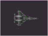
图2是实施案例1中对目标采用改进的现有成像方法的成像结果图;FIG. 2 is an imaging result diagram of using the improved existing imaging method for the target in the implementation case 1;
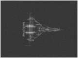
图3是实施案例1中对目标采用接上本自适应处理方法后的现有成像方法的成像结果图;Fig. 3 is the imaging result diagram of the existing imaging method after the adaptive processing method is applied to the target in the implementation case 1;
图4是实施案例2中对目标采用接上本自适应处理方法后的现有成像方法的成像结果图;Fig. 4 is the imaging result diagram of the existing imaging method after the adaptive processing method is applied to the target in the implementation case 2;
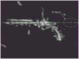
图5是实施案例2中采用平均划分子孔径的旧成像方法的存在严重旁瓣散焦的成像结果图;FIG. 5 is a graph of the imaging result with severe sidelobe defocusing using the old imaging method of evenly dividing sub-apertures in implementation case 2;
图6是实施案例2中对图5进行自适应识别旁瓣散焦识别的标记结果图。FIG. 6 is a graph showing the labeling result of adaptively identifying side lobe defocusing identification of FIG. 5 in Example 2. FIG.
具体实施方式Detailed ways
下面结合附图及实施例,详细描述本发明的技术方案:Below in conjunction with the accompanying drawings and the embodiments, the technical solutions of the present invention are described in detail:
参照附图1,本发明的具体实施步骤如下:With reference to accompanying drawing 1, the specific implementation steps of the present invention are as follows:
(1)从现有算法得到的备选子孔径边界点中自适应识别受强散射能量影响的边界点(1) Adaptive identification of boundary points affected by strong scattering energy from candidate sub-aperture boundary points obtained by existing algorithms
首先从现有成像方法中输入一组备选的子孔径边界点:First input a set of candidate subaperture boundary points from existing imaging methods:
θi,i=1,2,…,L (公式1)θi , i=1,2,...,L (Equation 1)
其中L为子孔径边界点数量;where L is the number of sub-aperture boundary points;
第二步计算目标散射能量与角度的函数:I(θ,n)和Q(θ,n)分别表示回波信号的实部与虚部,θ表示慢时间方位角度,n表示快时间采样,对于成像场景中仅存在唯一目标的实测数据,目标散射能量与角度的函数可以近似表示为:The second step calculates the function of target scattering energy and angle: I(θ,n) and Q(θ,n) represent the real part and imaginary part of the echo signal, respectively, θ represents the slow-time azimuth angle, n represents the fast-time sampling, For the measured data with only a single target in the imaging scene, the function of target scattering energy and angle can be approximately expressed as:

第三步为每个子孔径边界生成附近的回波能量函数:The third step generates a nearby echo energy function for each subaperture boundary:
PH(θ)i=PH(σ),σ∈(θi-2,θi+2) (公式3)PH(θ)i = PH(σ), σ∈(θi-2 ,θi+2 ) (Equation 3)
第四步计算每个回波能量函数的变异系数:The fourth step calculates the coefficient of variation for each echo energy function:
COV(i)=STD[PH(θ)i]/MEAN[PH(θ)i] (公式4)COV(i)=STD[PH(θ)i ]/MEAN[PH(θ)i ] (Equation 4)
其中STD[·]表示求标准差,MEAN[·]表示求平均值;Among them, STD[·] represents the standard deviation, and MEAN[·] represents the average value;
最后从子孔径边界点组中去除对应变异系数COV(i)>0.5的子孔径边界点,并将处理后的子孔径边界点组输出到现有成像方法。Finally, the sub-aperture boundary points corresponding to the coefficient of variation COV(i)>0.5 are removed from the sub-aperture boundary point group, and the processed sub-aperture boundary point group is output to the existing imaging method.
(2)从现有算法得到的成像结果中自适应得到背景分割门限,并绘制图像(2) The background segmentation threshold is adaptively obtained from the imaging results obtained by the existing algorithm, and the image is drawn
首先从现有成像算法中输入成像结果的矩阵:First input a matrix of imaging results from existing imaging algorithms:
Image(x,y) (公式5)Image(x,y) (Equation 5)
其中Image(x,y)的值为对应位置的归一化雷达散射截面(RCS)的对数。其中探测目标的RCS较大,背景RCS较小,通过一个门限将背景RCS去掉就能得到探测目标的图像。The value of Image(x,y) is the logarithm of the normalized radar cross section (RCS) of the corresponding position. Among them, the RCS of the detection target is larger, and the RCS of the background is smaller. The image of the detection target can be obtained by removing the RCS of the background through a threshold.
第二步选取门限,提取出Image(x,y)中值大于门限的点。其中Image(x,y)的最大值减小1DB为初始门限:The second step selects the threshold, and extracts the points whose values in Image(x, y) are greater than the threshold. Among them, the maximum value of Image(x, y) is reduced by 1DB as the initial threshold:
Image2(x,y)=Image(xi,yj),Image(xi,yj)>Threshold (公式6)Image2(x,y)=Image(xi ,yj ), Image(xi ,yj )>Threshold (Equation 6)
其中Image2(x,y)的其他值均为Threshold,Threshold为当前门限值。The other values of Image2(x,y) are Threshold, and Threshold is the current threshold value.
第三步对Image2(x,y)做闭运算,闭运算的算子为一个奇数边长的,边长接近Image2(x,y)边长1/64的正方形矩阵:The third step is to perform a closing operation on Image2(x,y), and the operator of the closing operation is a square matrix with an odd side length, and the side length is close to 1/64 of the side length of Image2(x,y):
Image3(x,y)=imclose[Image2(x,y),se] (公式7)Image3(x,y)=imclose[Image2(x,y),se] (Equation 7)
其中imclose[·]表示闭操作,se表示闭运算算子。Where imclose[ ] represents the closing operation, and se represents the closing operator.
第四步统计Image3(x,y)与Image2(x,y)中中心点位置和面积都相差在10以内的连通区域数量:The fourth step is to count the number of connected regions in Image3(x,y) and Image2(x,y) whose center point position and area are within 10 difference:
Num=countnearbyregion{label[Image3(x,y)],label[Image2(x,y)]} (公式8)Num=countnearbyregion{label[Image3(x,y)],label[Image2(x,y)]} (Equation 8)
其中countnearbyregion{·}表示统计中心点位置和面积都相差在10以内的连通区域数量,label[·]表示求矩阵的连通区域。Among them, countnearbyregion{·} indicates the number of connected regions whose center point position and area differ by less than 10, and label[·] indicates the connected region of the matrix.
第五步如果Num≤15,将现有门限减小1DB,从第二步开始重复执行。如果Num>15,将现有门限增大1DB作为最佳分割门限。并绘制图像:In the fifth step, if Num≤15, reduce the existing threshold by 1DB, and repeat the execution from the second step. If Num>15, increase the existing threshold by 1DB as the best segmentation threshold. and draw the image:
Imagesc(Image4),Image4(x,y)=Image(xi,yj),Image(xi,yj)Imagesc(Image4), Image4(x,y)=Image(xi ,yj ), Image(xi ,yj )
>BestThreshold (公式9)>BestThreshold (Equation 9)
其中Imagesc(·)表示根据RCS矩阵绘制图像,Image4(x,y)的其他值均为BestThreshold,BestThreshold为最佳分割门限。Among them, Imagesc(·) means to draw an image according to the RCS matrix, and other values of Image4(x, y) are BestThreshold, and BestThreshold is the best segmentation threshold.
(3)从绘制好的图像中自适应识别是否存在严重的旁瓣散焦(3) Adaptively identify whether there is serious sidelobe defocus from the drawn image
首先从步骤(2)中输入分割好的RCS矩阵Image4;First, input the segmented RCS matrix Image4 from step (2);
第二步从RCS矩阵Image4中寻找散射点的中心:The second step is to find the center of the scattering point from the RCS matrix Image4:
Points(x,y)i=Points(xm,xn),i=1,2,…,L.Points(xn,xn)Points(x,y)i =Points(xm ,xn ),i=1,2,...,L.Points(xn ,xn )
>8Neighborhood[Points(xm,xn)] (公式10)>8Neighborhood[Points(xm ,xn )] (Equation 10)
其中Points(x,y)i为散射点中心,L为散射点数量。8Neighborhood[·]表示一个点的8邻域。where Points(x,y)i is the center of the scattering point, and L is the number of scattering points. 8Neighborhood[ ] represents the 8-neighborhood of a point.
第三步寻找每个散射点最近的6个相邻散射点编号:The third step is to find the nearest 6 adjacent scatter point numbers for each scatter point:
NearPoits(i,:)=mindistance[Points(x,y)i]i=1,2,…,L (公式11)NearPoits(i,:)=mindistance[Points(x,y)i ]i=1,2,...,L (Equation 11)
其中NearPoits(i,:)表示离第i个散射点最近的6个相邻散射点编号向量,mindistance[·]表示求离对应散射点最近的6个相邻散射点编号。Among them, NearPoits(i,:) represents the number vector of the 6 adjacent scatter points closest to the ith scatter point, and mindistance[·] represents the number of the 6 adjacent scatter points closest to the corresponding scatter point.
第四步为每个散射点与6个相邻散射点的其中5个计算两两之间的角度:The fourth step calculates the angle between each scatter point and 5 of the 6 adjacent scatter points:
angles(i,j,:)=getanles[Points(x,y)m,Points(x,y)n]i=1,2,…,L,j=1,2,…,6 (公式12)angles(i,j,:)=getanles[Points(x,y)m ,Points(x,y)n ]i=1,2,…,L,j=1,2,…,6 (Equation 12)
其中angles(i,j,:)表示去掉其中一个相邻散射点之后第i个散射点与其他5个相邻散射点两两之间的角度,getanles[·]表示求两个散射点之间的角度,Points(x,y)m与Points(x,y)n表示包括第i个散射点与其他5个相邻散射点的共6个散射点;where angles(i,j,:) represents the angle between the i-th scatter point and the other 5 adjacent scatter points after removing one of the adjacent scatter points, and getanles[ ] represents the distance between the two scatter points The angle of , Points(x,y)m and Points(x,y)n represent a total of 6 scattering points including the i-th scattering point and the other 5 adjacent scattering points;
第五步判断每个散射点与其周围的6个相邻散射点是否大致排列为一条直线:The fifth step is to determine whether each scattering point and its surrounding 6 adjacent scattering points are roughly arranged in a straight line:
min{max[angles(i,j,:)]-min[angles(i,j,:)]}<10°j=1,2,…,6 (公式13)min{max[angles(i,j,:)]-min[angles(i,j,:)]}<10°j=1,2,…,6 (Equation 13)
其中该判断条件为该散射点与其中5个相邻散射点两两之间的角度的差距是否可以小于10°。The judgment condition is whether the angle difference between the scattering point and the five adjacent scattering points can be less than 10°.
第六步如果第五步没有找到符合条件的散射点,输出旁瓣散焦识别变量为0(FALSE)。否则输出旁瓣散焦识别变量为1(TRUE),并在图像中标记出旁瓣散焦位置:The sixth step If the fifth step does not find a qualified scattering point, the output sidelobe defocus identification variable is 0 (FALSE). Otherwise, the output sidelobe defocus identification variable is 1 (TRUE), and the sidelobe defocus position is marked in the image:
plot(x,y,′r*′) (公式14)plot(x,y,'r*') (Equation 14)
其中x、y为符合条件的散射点坐标,plot(·,·,′r*′)为在图像指定位置标记星号。Where x and y are the coordinates of the scatter points that meet the conditions, and plot(·,·,'r*') is to mark the asterisk at the specified position of the image.
下面结合实测数据对本发明的效果作进一步说明。The effect of the present invention will be further described below in conjunction with the measured data.
实施例1Example 1
利用工作带宽28.8GHz的0.34THz雷达系统采集实测数据。将J15飞机模型作为CSAR成像目标,其尺寸为44.5cm×30cm。飞机模型与真实飞机的尺寸比例为1:50。目标放置在距离雷达天线4.02米处的泡沫平台上,与雷达天线的相对高度为0.42m。雷达天线到泡沫平台中心的斜视角近视为6°。雷达角速度为4°/s,载波322.02GHz,带宽28.8GHz,脉冲宽度0.3ms,快时间采样频率1.5625MHz,脉冲重复频率1000Hz。The measured data is collected by a 0.34THz radar system with a working bandwidth of 28.8GHz. The J15 aircraft model is used as the CSAR imaging target, and its size is 44.5cm×30cm. The size ratio of the aircraft model to the real aircraft is 1:50. The target is placed on a foam platform at a distance of 4.02 meters from the radar antenna, and the relative height to the radar antenna is 0.42 meters. The oblique angle of the radar antenna to the center of the foam platform is close to 6°. The radar angular velocity is 4°/s, the carrier is 322.02GHz, the bandwidth is 28.8GHz, the pulse width is 0.3ms, the fast time sampling frequency is 1.5625MHz, and the pulse repetition frequency is 1000Hz.
对该回波数据使用现有基于子孔径相邻互相关系数的自适应子孔径划分方法,并根据得到的子孔径高分辨成像,成像结果见附图2。该成像方法原本设置了五个参数,其中三个是必要的:强散射能量门限设置为1倍目标散射能量的平均值,能量门限设置为最大能量的0.08倍,子孔径宽度门限设置为4°。另两个参数的根本目的是获得备选子孔径边界点,可以通过改进备选子孔径边界点获取算法省去。实验时采用直接将相邻互相关系数区间最小值点作为备选子孔径边界点的方式省去这两个参数,反而提升了该算法对不同目标的适应性。此外在得到成像结果之后接上步骤(2)所述自适应处理方法绘制图像,自适应得到的最佳分割门限为42DB,与原成像方法人工判断时的结论相同。An existing adaptive sub-aperture division method based on the adjacent cross-correlation coefficients of sub-apertures is used for the echo data, and high-resolution imaging of the sub-apertures is obtained. The imaging results are shown in FIG. 2 . The imaging method originally set five parameters, three of which are necessary: the strong scattering energy threshold is set to 1 times the average value of the target scattering energy, the energy threshold is set to 0.08 times the maximum energy, and the subaperture width threshold is set to 4° . The fundamental purpose of the other two parameters is to obtain candidate sub-aperture boundary points, which can be omitted by improving the candidate sub-aperture boundary point acquisition algorithm. In the experiment, the minimum point of the adjacent cross-correlation coefficient interval is directly used as the candidate sub-aperture boundary point to omit these two parameters, which improves the adaptability of the algorithm to different targets. In addition, after the imaging result is obtained, the adaptive processing method described in step (2) is used to draw the image, and the optimal segmentation threshold obtained by the adaptive method is 42DB, which is the same as the conclusion in the manual judgment of the original imaging method.
对该回波数据使用进一步改进的高分辨成像方法,其中需要原本的三个必要参数的备选子孔径边界处理环节替换为步骤(1)所述自适应处理方法,成像结果见附图3。步骤(2)所述自适应处理方法自适应得到的最佳分割门限为43DB,与原成像方法人工判断时的结论相同。该成像方法接上步骤(1)、(2)所述自适应处理方法之后完全不需要人工参与成像过程,并且成像效果与现有方法差距不大,成像效果差异的主要原因是最佳分割门限的改变。A further improved high-resolution imaging method is used for the echo data, wherein the alternative sub-aperture boundary processing link that requires the original three necessary parameters is replaced by the adaptive processing method described in step (1). The imaging results are shown in FIG. 3 . The optimal segmentation threshold obtained by the adaptive processing method in step (2) is 43DB, which is the same as the conclusion in the manual judgment of the original imaging method. After the imaging method is connected to the adaptive processing method described in steps (1) and (2), it does not require manual participation in the imaging process at all, and the imaging effect is not far from the existing method. The main reason for the difference in imaging effect is the optimal segmentation threshold change.
实施例2:Example 2:
利用工作带宽28.8GHz的0.34THz雷达系统采集实测数据。将左轮手枪模型作为CSAR成像目标。目标放置在距离雷达天线3.85米处的泡沫平台上,雷达角速度为8°/s,载波322.02GHz,带宽28.8GHz,脉冲宽度0.3ms,快时间采样频率1.5625MHz,脉冲重复频率1000Hz。The measured data is collected by a 0.34THz radar system with a working bandwidth of 28.8GHz. Use the revolver model as the CSAR imaging target. The target is placed on a foam platform at a distance of 3.85 meters from the radar antenna. The radar angular velocity is 8°/s, the carrier wave is 322.02GHz, the bandwidth is 28.8GHz, the pulse width is 0.3ms, the fast time sampling frequency is 1.5625MHz, and the pulse repetition frequency is 1000Hz.
对该回波数据使用接上步骤(1)、(2)所述自适应处理方法之后的高分辨成像方法,成像结果见附图4,成像过程完全不需要人工参与。对该成像结果使用步骤(3)所述自适应处理方法自适应识别旁瓣散焦,结果返回0(FALSE)。The high-resolution imaging method followed by the adaptive processing method described in steps (1) and (2) is used for the echo data. The imaging results are shown in FIG. 4 , and the imaging process does not require manual participation at all. Use the adaptive processing method described in step (3) to adaptively identify side lobe defocusing on the imaging result, and the result returns 0 (FALSE).
对该回波数据使用传统微波雷达采用的平均划分子孔径的子孔径划分方法,并根据得到的子孔径高分辨成像,成像结果见附图5,箭头标记处为严重的旁瓣散焦。对该成像结果使用步骤(3)所述自适应处理方法自适应识别旁瓣散焦,结果返回1(TRUE),标记以后的成像结果见附图6。The sub-aperture division method of the average sub-aperture division adopted by the traditional microwave radar is used for the echo data, and the high-resolution imaging of the sub-aperture is obtained. Use the adaptive processing method described in step (3) to adaptively identify side lobe defocusing on the imaging result, and the result returns 1 (TRUE). The imaging results after marking are shown in FIG. 6 .
Claims (1)

Priority Applications (1)
| Application Number | Priority Date | Filing Date | Title |
|---|---|---|---|
| CN202010488574.3ACN111580105B (en) | 2020-06-02 | 2020-06-02 | An adaptive processing method for high-resolution imaging of terahertz radar |
Applications Claiming Priority (1)
| Application Number | Priority Date | Filing Date | Title |
|---|---|---|---|
| CN202010488574.3ACN111580105B (en) | 2020-06-02 | 2020-06-02 | An adaptive processing method for high-resolution imaging of terahertz radar |
Publications (2)
| Publication Number | Publication Date |
|---|---|
| CN111580105Atrue CN111580105A (en) | 2020-08-25 |
| CN111580105B CN111580105B (en) | 2022-05-13 |
Family
ID=72116039
Family Applications (1)
| Application Number | Title | Priority Date | Filing Date |
|---|---|---|---|
| CN202010488574.3AActiveCN111580105B (en) | 2020-06-02 | 2020-06-02 | An adaptive processing method for high-resolution imaging of terahertz radar |
Country Status (1)
| Country | Link |
|---|---|
| CN (1) | CN111580105B (en) |
Cited By (2)
| Publication number | Priority date | Publication date | Assignee | Title |
|---|---|---|---|---|
| CN113484842A (en)* | 2021-09-08 | 2021-10-08 | 中国人民解放军国防科技大学 | RCS reconstruction method based on target attitude framing and scattering dictionary truncation |
| CN116540232A (en)* | 2023-04-28 | 2023-08-04 | 中国人民解放军陆军工程大学 | CSAR imaging method, device and storage medium based on adaptive overlapping sub-aperture |
Citations (13)
| Publication number | Priority date | Publication date | Assignee | Title |
|---|---|---|---|---|
| JP2001281332A (en)* | 2000-03-30 | 2001-10-10 | Mitsubishi Electric Corp | Synthetic aperture radar apparatus and target image reproducing method |
| US6388606B1 (en)* | 1999-08-18 | 2002-05-14 | Deutsches Zentrum Fur Luft-Und Raumfahrt E.V. | Aircraft or spacecraft based synthetic aperture radar |
| EP1766433A1 (en)* | 2004-07-07 | 2007-03-28 | Koninklijke Philips Electronics N.V. | Improvements in or relating to time-of-flight ranging systems |
| CN101221239A (en)* | 2008-01-25 | 2008-07-16 | 电子科技大学 | A Segmentation Method of Synthetic Aperture Radar Image Based on Level Set |
| CN101714252A (en)* | 2009-11-26 | 2010-05-26 | 上海电机学院 | Method for extracting road in SAR image |
| CN102620681A (en)* | 2012-03-31 | 2012-08-01 | 中国科学院光电技术研究所 | Detection system and detection method for extra-large-diameter convex hyperboloid mirror zonal division |
| CN107238821A (en)* | 2017-05-31 | 2017-10-10 | 中国电子科技集团公司第二十九研究所 | The airfield runway foreign matter detecting method and device of a kind of feature based spectrum signature |
| CN107589421A (en)* | 2017-10-31 | 2018-01-16 | 西安电子科技大学 | A kind of array Forward-looking SAR imaging method |
| US20180183650A1 (en)* | 2012-12-05 | 2018-06-28 | Origin Wireless, Inc. | Method, apparatus, and system for object tracking and navigation |
| CN108387896A (en)* | 2018-01-03 | 2018-08-10 | 厦门大学 | A kind of automatic convergence imaging method based on Ground Penetrating Radar echo data |
| CN108508439A (en)* | 2018-05-01 | 2018-09-07 | 南京理工大学 | The method that double carried SARs position target cooperative imaging volume |
| WO2019069787A1 (en)* | 2017-10-02 | 2019-04-11 | 日本電気株式会社 | Radar image processing device, radar image processing method, and radar image processing program |
| US20190212435A1 (en)* | 2016-08-31 | 2019-07-11 | Siemens Aktiengesellschaft | Method and Assembly for Monitoring a Hot Gas Region of a Gas Turbine |
- 2020
- 2020-06-02CNCN202010488574.3Apatent/CN111580105B/enactiveActive
Patent Citations (13)
| Publication number | Priority date | Publication date | Assignee | Title |
|---|---|---|---|---|
| US6388606B1 (en)* | 1999-08-18 | 2002-05-14 | Deutsches Zentrum Fur Luft-Und Raumfahrt E.V. | Aircraft or spacecraft based synthetic aperture radar |
| JP2001281332A (en)* | 2000-03-30 | 2001-10-10 | Mitsubishi Electric Corp | Synthetic aperture radar apparatus and target image reproducing method |
| EP1766433A1 (en)* | 2004-07-07 | 2007-03-28 | Koninklijke Philips Electronics N.V. | Improvements in or relating to time-of-flight ranging systems |
| CN101221239A (en)* | 2008-01-25 | 2008-07-16 | 电子科技大学 | A Segmentation Method of Synthetic Aperture Radar Image Based on Level Set |
| CN101714252A (en)* | 2009-11-26 | 2010-05-26 | 上海电机学院 | Method for extracting road in SAR image |
| CN102620681A (en)* | 2012-03-31 | 2012-08-01 | 中国科学院光电技术研究所 | Detection system and detection method for extra-large-diameter convex hyperboloid mirror zonal division |
| US20180183650A1 (en)* | 2012-12-05 | 2018-06-28 | Origin Wireless, Inc. | Method, apparatus, and system for object tracking and navigation |
| US20190212435A1 (en)* | 2016-08-31 | 2019-07-11 | Siemens Aktiengesellschaft | Method and Assembly for Monitoring a Hot Gas Region of a Gas Turbine |
| CN107238821A (en)* | 2017-05-31 | 2017-10-10 | 中国电子科技集团公司第二十九研究所 | The airfield runway foreign matter detecting method and device of a kind of feature based spectrum signature |
| WO2019069787A1 (en)* | 2017-10-02 | 2019-04-11 | 日本電気株式会社 | Radar image processing device, radar image processing method, and radar image processing program |
| CN107589421A (en)* | 2017-10-31 | 2018-01-16 | 西安电子科技大学 | A kind of array Forward-looking SAR imaging method |
| CN108387896A (en)* | 2018-01-03 | 2018-08-10 | 厦门大学 | A kind of automatic convergence imaging method based on Ground Penetrating Radar echo data |
| CN108508439A (en)* | 2018-05-01 | 2018-09-07 | 南京理工大学 | The method that double carried SARs position target cooperative imaging volume |
Non-Patent Citations (3)
| Title |
|---|
| E. ERTIN 等: ""Interferometric methods for three-dimensional target reconstruction with multipass circular SAR"", 《IET RADAR, SONAR NAVIGAT.》* |
| TONG LIU 等: ""Wide-Angle CSAR Imaging Based on the Adaptive Subaperture Partition Method in the Terahertz Band"", 《IEEE TRANSACTIONS ON TERAHERTZ SCIENCE AND TECHNOLOGY》* |
| 魏明贵 等: ""太赫兹时域雷达成像研究"", 《雷达学报》* |
Cited By (4)
| Publication number | Priority date | Publication date | Assignee | Title |
|---|---|---|---|---|
| CN113484842A (en)* | 2021-09-08 | 2021-10-08 | 中国人民解放军国防科技大学 | RCS reconstruction method based on target attitude framing and scattering dictionary truncation |
| CN113484842B (en)* | 2021-09-08 | 2021-11-12 | 中国人民解放军国防科技大学 | RCS Reconstruction Method Based on Target Attitude Framing and Scattering Dictionary Truncation |
| CN116540232A (en)* | 2023-04-28 | 2023-08-04 | 中国人民解放军陆军工程大学 | CSAR imaging method, device and storage medium based on adaptive overlapping sub-aperture |
| CN116540232B (en)* | 2023-04-28 | 2024-01-26 | 中国人民解放军陆军工程大学 | CSAR imaging method, equipment and storage medium based on adaptive overlapping subapertures |
Also Published As
| Publication number | Publication date |
|---|---|
| CN111580105B (en) | 2022-05-13 |
Similar Documents
| Publication | Publication Date | Title |
|---|---|---|
| CN110473260B (en) | Wave video measuring device and method | |
| CN108734111A (en) | SAR image surface vessel recognition methods | |
| CN113362293A (en) | SAR image ship target rapid detection method based on significance | |
| CN109782274B (en) | Water damage identification method based on time-frequency statistical characteristics of ground penetrating radar signals | |
| CN110223302A (en) | A kind of naval vessel multi-target detection method extracted based on rotary area | |
| CN111580105B (en) | An adaptive processing method for high-resolution imaging of terahertz radar | |
| CN107578441B (en) | Uniform distribution method of infrared brightness temperature deviation angle gradient for tropical cyclone center location | |
| CN105974412B (en) | A kind of target's feature-extraction method for synthetic aperture radar | |
| CN106908781B (en) | Acquisition Method of Velocity Vector of Linear Moving Target Based on Single-channel Circular SAR | |
| CN109100697B (en) | Target condensation method based on ground monitoring radar system | |
| CN106156758B (en) | A kind of tidal saltmarsh method in SAR seashore image | |
| CN116740332A (en) | Method for positioning center and measuring angle of space target component on satellite based on region detection | |
| CN108983194B (en) | Target extraction and condensation method based on ground monitoring radar system | |
| CN107610130B (en) | Sea-land clutter scene segmentation method based on ratio of amplitude to phase linearity | |
| Wang et al. | DBSCAN clustering algorithm of millimeter wave radar based on multi frame joint | |
| CN117575977A (en) | Follicular region enhancement method for ovarian tissue analysis | |
| CN105844644B (en) | Extra large land clutter Scene Segmentation based on morphology intermediate value derivative | |
| Cao et al. | Optimal time selection for ISAR imaging of ship target via novel approach of centerline extraction with RANSAC algorithm | |
| CN107909595A (en) | Extra large land clutter Scene Segmentation based on amplitude Yu energy compaction measure product | |
| CN114067064B (en) | Target three-dimensional reconstruction method based on multi-view radar image | |
| CN103714542B (en) | Extraction method for target highlight in low-resolution high-frequency sonar image | |
| CN118483665A (en) | A radar atmospheric correction method based on spatial autocorrelation clustering | |
| CN111583267A (en) | Fast SAR Image Sidelobe Suppression Method Based on Generalized Fuzzy C-Means Clustering | |
| CN115546627B (en) | Unsupervised change detection method for polarimetric SAR images based on regional relative peak and VIT | |
| CN116203556A (en) | Indoor human target point cloud detection method and system based on millimeter wave radar |
Legal Events
| Date | Code | Title | Description |
|---|---|---|---|
| PB01 | Publication | ||
| PB01 | Publication | ||
| SE01 | Entry into force of request for substantive examination | ||
| SE01 | Entry into force of request for substantive examination | ||
| GR01 | Patent grant | ||
| GR01 | Patent grant |