CN111579227B - A test equipment for testing the mechanical properties of deep-water cage floating frame structures - Google Patents
A test equipment for testing the mechanical properties of deep-water cage floating frame structuresDownload PDFInfo
- Publication number
- CN111579227B CN111579227BCN202010405276.3ACN202010405276ACN111579227BCN 111579227 BCN111579227 BCN 111579227BCN 202010405276 ACN202010405276 ACN 202010405276ACN 111579227 BCN111579227 BCN 111579227B
- Authority
- CN
- China
- Prior art keywords
- frame
- floating
- force application
- application device
- lifting force
- Prior art date
- Legal status (The legal status is an assumption and is not a legal conclusion. Google has not performed a legal analysis and makes no representation as to the accuracy of the status listed.)
- Expired - Fee Related
Links
Images


Classifications
- G—PHYSICS
- G01—MEASURING; TESTING
- G01M—TESTING STATIC OR DYNAMIC BALANCE OF MACHINES OR STRUCTURES; TESTING OF STRUCTURES OR APPARATUS, NOT OTHERWISE PROVIDED FOR
- G01M13/00—Testing of machine parts
- G—PHYSICS
- G01—MEASURING; TESTING
- G01N—INVESTIGATING OR ANALYSING MATERIALS BY DETERMINING THEIR CHEMICAL OR PHYSICAL PROPERTIES
- G01N3/00—Investigating strength properties of solid materials by application of mechanical stress
- G01N3/02—Details
- G—PHYSICS
- G01—MEASURING; TESTING
- G01N—INVESTIGATING OR ANALYSING MATERIALS BY DETERMINING THEIR CHEMICAL OR PHYSICAL PROPERTIES
- G01N3/00—Investigating strength properties of solid materials by application of mechanical stress
- G01N3/08—Investigating strength properties of solid materials by application of mechanical stress by applying steady tensile or compressive forces
- G01N3/10—Investigating strength properties of solid materials by application of mechanical stress by applying steady tensile or compressive forces generated by pneumatic or hydraulic pressure
- G—PHYSICS
- G01—MEASURING; TESTING
- G01N—INVESTIGATING OR ANALYSING MATERIALS BY DETERMINING THEIR CHEMICAL OR PHYSICAL PROPERTIES
- G01N3/00—Investigating strength properties of solid materials by application of mechanical stress
- G01N3/20—Investigating strength properties of solid materials by application of mechanical stress by applying steady bending forces
- Y—GENERAL TAGGING OF NEW TECHNOLOGICAL DEVELOPMENTS; GENERAL TAGGING OF CROSS-SECTIONAL TECHNOLOGIES SPANNING OVER SEVERAL SECTIONS OF THE IPC; TECHNICAL SUBJECTS COVERED BY FORMER USPC CROSS-REFERENCE ART COLLECTIONS [XRACs] AND DIGESTS
- Y02—TECHNOLOGIES OR APPLICATIONS FOR MITIGATION OR ADAPTATION AGAINST CLIMATE CHANGE
- Y02A—TECHNOLOGIES FOR ADAPTATION TO CLIMATE CHANGE
- Y02A40/00—Adaptation technologies in agriculture, forestry, livestock or agroalimentary production
- Y02A40/80—Adaptation technologies in agriculture, forestry, livestock or agroalimentary production in fisheries management
- Y02A40/81—Aquaculture, e.g. of fish
Landscapes
- Physics & Mathematics (AREA)
- General Physics & Mathematics (AREA)
- Health & Medical Sciences (AREA)
- Life Sciences & Earth Sciences (AREA)
- Chemical & Material Sciences (AREA)
- Analytical Chemistry (AREA)
- Biochemistry (AREA)
- General Health & Medical Sciences (AREA)
- Immunology (AREA)
- Pathology (AREA)
- Investigating Strength Of Materials By Application Of Mechanical Stress (AREA)
- Testing Of Devices, Machine Parts, Or Other Structures Thereof (AREA)
Abstract
Description
Translated fromChinese技术领域technical field
本发明涉及一种用于测试深水网箱浮架结构力学性能的试验设备。The invention relates to a test device for testing the mechanical performance of a deep-water net cage floating frame structure.
背景技术Background technique
高密度聚乙烯(HDPE)重力式网箱具有性价比高、养殖容量大等优势,为了减轻近岸环境压力不断向深远海域发展,网箱系统可能由于无法承受波浪环境的过大载荷而屈服变形,尤其在面对超强台风侵袭时塑性屈服现象依然较严重。High-density polyethylene (HDPE) gravity cages have the advantages of high cost performance and large breeding capacity. In order to reduce the pressure of the near-shore environment and continue to develop into the deep sea, the cage system may yield and deform due to the excessive load of the wave environment. Especially in the face of super typhoon attack, the phenomenon of plastic yielding is still serious.
其中,浮架结构为网箱系统的关键受力构件,浮架结构的失效将导致整个网箱系统的破坏,因此,设计及应用试验设备测定浮架结构的力学性能具有重要的理论价值和应用价值。Among them, the floating frame structure is the key stress-bearing component of the cage system, and the failure of the floating frame structure will lead to the destruction of the entire cage system. Therefore, the design and application of test equipment to measure the mechanical properties of the floating frame structure has important theoretical value and application value.
海上网箱作业过程中,在持续的波浪载荷作用下,网箱的浮架结构的塑性破坏通常发生在系泊处、焊缝处、浮管与工字架的联接处,工字架与双浮管的联接设置对网箱的力学性能影响较大,对工字架与浮管组装成的联接结构的强度进行测试即可获得浮架结构的实际结构强度。During the operation of offshore cages, under continuous wave loads, the plastic failure of the floating frame structure of the cage usually occurs at the moorings, welds, joints between the floating pipe and the I-shaped frame, and the I-shaped frame and the double frame. The connection setting of the floating pipe has a great influence on the mechanical properties of the cage. The actual structural strength of the floating frame structure can be obtained by testing the strength of the connection structure assembled by the I-shaped frame and the floating pipe.
而,目前对于网箱的浮架结构的测试只是对其中的浮管材料进行力学性能测试,测试时会将浮管加工为标准试样。而在将整体的浮管加工成标准试样的过程中会容易在浮管表面产生划痕、扭曲凹陷及缺口,这些会引起应力集中影响测试结果。且上述的测试只能对浮管进行测试,而不能对未经机加工的浮架结构的力学性能进行测试。且流固耦合及水动力试验因很难满足刚度相似条件而几乎无法直观模拟网箱塑性变形。However, the current test for the floating frame structure of the net cage is only to test the mechanical properties of the floating tube material, and the floating tube will be processed into a standard sample during the test. However, in the process of processing the integral floating tube into a standard sample, scratches, twisted dents and notches are likely to occur on the surface of the floating tube, which will cause stress concentration and affect the test results. And the above-mentioned test can only test the floating tube, but not the mechanical properties of the unmachined floating frame structure. Moreover, the fluid-solid coupling and hydrodynamic tests can hardly simulate the plastic deformation of the cage intuitively because it is difficult to meet the similar stiffness conditions.
作业网箱系统长期承受波浪动态缓冲力的影响,尤其在台风期高振幅、高频率交变应力作用下的结构疲劳更需要评估校准。The operating cage system has been subjected to the impact of wave dynamic buffering force for a long time, especially the structural fatigue under the action of high amplitude and high frequency alternating stress during the typhoon period needs to be evaluated and calibrated.
发明内容Contents of the invention
本发明所要解决的技术问题,就是提供一种用于测试深水网箱浮架结构力学性能的试验设备,其可对网箱浮架结构开展力学性能的试验。The technical problem to be solved by the present invention is to provide a test device for testing the mechanical properties of the floating frame structure of the deep-water net cage, which can carry out the test of the mechanical properties of the floating frame structure of the net cage.
解决上述技术问题,本发明采用的技术方案如下:To solve the problems of the technologies described above, the technical scheme adopted in the present invention is as follows:
一种用于测试深水网箱浮架结构力学性能的试验设备,其特征在于:包括防护架、升降施力装置、力学传感器、施力架、夹具架和计算机,防护架内设有实验空间,实验空间的内底面为水平工作面,夹具架固定设在水平工作面上,且夹具架的位置可调节,夹具架用于固定待测试包含有工字架与浮管的浮架结构的两端,升降施力装置安装在防护架的上端,且升降施力装置可前后左右调节,施力架设在升降施力装置的下活动端,由升降施力装置带动施力架作升降运动,以通过施力架对浮架结构的工字架位置、浮管位置或者焊接位置施加向下的载荷力、向上的载荷力或者上下振动力,力学传感器设在施力架与升降施力装置的下活动端之间,用于测得作用在施力架上的力,计算机接收力学传感器输出的载荷信号,计算机还接收升降施力装置的升降位移信号。A test equipment for testing the mechanical properties of the floating structure of deep water net cages, characterized in that it includes a protective frame, a lifting force applying device, a mechanical sensor, a force applying frame, a clamp frame and a computer, and an experimental space is provided in the protective frame. The inner bottom surface of the experimental space is a horizontal working surface. The fixture frame is fixed on the horizontal working surface, and the position of the fixture frame can be adjusted. The fixture frame is used to fix the two ends of the floating frame structure including the I-shaped frame and the floating tube to be tested. , the lifting force applying device is installed on the upper end of the protective frame, and the lifting force applying device can be adjusted front, back, left, and right. The force-applying frame applies downward load force, upward load force or up-and-down vibration force to the I-frame position, floating pipe position or welding position of the floating frame structure. Between the ends, it is used to measure the force acting on the force-applying frame. The computer receives the load signal output by the mechanical sensor, and the computer also receives the lifting displacement signal of the lifting force-applying device.
本发明的试验设备还包括横梁,横梁通过前后滑动滚轮可前后调节安装在防护架的上边,升降施力装置通过左右滑动滚轮可左右调节安装在横梁上。本发明通过横梁及其上的前后滑动滚轮实现前后调节。The test equipment of the present invention also includes a crossbeam, the crossbeam can be adjusted forward and backward through the front and rear sliding rollers and is installed on the protective frame, and the lifting force applying device can be adjusted left and right through the left and right sliding rollers and installed on the crossbeam. The present invention realizes front and rear adjustment through the cross beam and the front and rear sliding rollers on it.
其中,升降施力装置包括气缸,气缸通过左右滑动滚轮可左右调节的安装在防护架的上端,气缸竖直向下。本发明通过左右滑动滚轮实现左右调节。Wherein, the lifting force applying device comprises a cylinder, which can be adjusted left and right through the left and right sliding rollers and is installed on the upper end of the protective frame, and the cylinder is vertically downward. The present invention realizes left and right adjustment by sliding roller left and right.
进一步的,在水平工作面上设有若干个固定螺纹孔,在水平工作面上面设有多个压杆,压杆通过固定螺栓固定在固定螺纹孔上,压杆的一端部压在夹具架的下边框上。压杆的设置实现了夹具架的位置可调节。Further, a number of fixed threaded holes are provided on the horizontal working surface, and a plurality of pressing rods are arranged on the horizontal working surface. The pressing rods are fixed on the fixing threaded holes through fixing bolts, and one end of the pressing rod is pressed against the clamp frame. on the lower border. The setting of the pressing bar realizes the adjustable position of the fixture frame.
其中,夹具架包括两个固定架,两个固定架分别用于固定浮管的两端。Wherein, the fixture frame includes two fixing frames, and the two fixing frames are respectively used for fixing the two ends of the floating tube.
进一步的,固定架上设有固定槽,浮管的端部通过绳索或夹具固定在固定槽中。Further, the fixing bracket is provided with a fixing groove, and the end of the floating pipe is fixed in the fixing groove by a rope or a clamp.
进一步的,防护架的周边设有防护网。Further, a protective net is provided around the protective frame.
本发明为了保证操作的安全,升降施力装置上设有用于控制其启动的电源开关、用于控制其下降的下移动开关和用于控制其上升的上移动开关,电源开关分别与下移动开关和上移动开关相关联设置,只有同时接通电源开关和下移动开关才能控制升降施力装置下降,只有同时接通电源开关和上移动开关才能控制升降施力装置上升。In order to ensure the safety of operation, the present invention is equipped with a power switch for controlling its startup, a lower moving switch for controlling its descent, and an upper moving switch for controlling its rising on the lifting force applying device. It is set in association with the upper movement switch. Only when the power switch and the lower movement switch are turned on at the same time can the lifting force applying device be controlled to descend, and only when the power switch and the upper movement switch are turned on simultaneously can the lifting force applying device be controlled to rise.
与现有技术相比,本发明具有以下有益效果:Compared with the prior art, the present invention has the following beneficial effects:
1、本发明通过夹具架固定浮架结构的两端,通过施力架对浮架结构的工字架、浮管或者焊接位置施加向下的载荷力、向上的载荷力或者上下振动力,再通过力学传感器向计算机输送测得的力的信号,从而可测试获得网箱浮架的弯曲、压缩、拉伸等网箱浮架结构的力学性能数据,实现了直接对网箱浮架结构开展力学性能的试验。本发明试验设备对网箱的进一步设计优化具有极大促进作用。1. The present invention fixes the two ends of the floating frame structure through the clamp frame, applies downward load force, upward load force or up and down vibration force to the I-shaped frame, floating pipe or welding position of the floating frame structure through the force frame, and then The measured force signal is transmitted to the computer through the mechanical sensor, so that the mechanical performance data of the cage floating frame structure such as bending, compression, and stretching can be tested and obtained, and the mechanical performance of the cage floating frame structure is realized directly. performance test. The test equipment of the present invention can greatly promote the further design and optimization of the net cage.
2、本发明针对浮架结构的浮管与工字架整体结构、局部结构或焊接结构开展强度试验,可对不同结构形式的网箱浮架结构进行力学性能测定。2. The present invention carries out strength tests on the overall structure, partial structure or welded structure of the floating tube and the I-frame of the floating frame structure, and can measure the mechanical properties of the floating frame structures of net cages with different structural forms.
3、采用夹具架紧固浮架结构的两端,施力架施加载荷力,以模拟波浪载荷及锚泊约束于浮架对应部位,能够精确模拟浮架在海上波浪环境下作业时的系泊力。3. The two ends of the floating frame structure are fastened by the clamp frame, and the load force is applied by the force frame to simulate the wave load and anchoring constraints on the corresponding parts of the floating frame, which can accurately simulate the mooring force of the floating frame when it operates in a sea wave environment .
附图说明Description of drawings
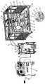
图1是本发明实施例一的立体结构示意图;FIG. 1 is a schematic diagram of a three-dimensional structure of
图2是本发明实施例一的横梁、气缸、力学传感器和施力架的装配结构示意图;Fig. 2 is a schematic diagram of the assembly structure of the beam, the cylinder, the mechanical sensor and the force applying frame according to the first embodiment of the present invention;
图3是本发明实施例一的固定架固定浮架结构的结构示意图;Fig. 3 is a structural schematic diagram of the structure of the fixed frame and the fixed floating frame in
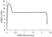
图4是本发明实施例一在浮管上施加载荷力进行试验时获得的压缩位移与压缩载荷之间的曲线图;Fig. 4 is the curve diagram between the compressive displacement and the compressive load obtained when the loading force is applied on the floating pipe in the embodiment of the present invention;
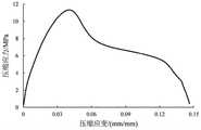
图5是本发明实施例一在浮管上施加载荷力进行试验时获得的压缩应力与压缩应变之间的曲线图;Fig. 5 is a curve diagram between compressive stress and compressive strain obtained when a load force is applied to a floating tube in an embodiment of the present invention;
图6是本发明实施例一在工字架上施加载荷力进行试验时获得的压缩应力与压缩应变之间的曲线图;Fig. 6 is the curve diagram between the compressive stress and the compressive strain obtained when the load force is applied on the I-shaped frame to test in the embodiment of the present invention;
图7是本发明实施例一在焊接的浮管上施加载荷力进行试验时获得的压缩应力与压缩应变之间的曲线图;Fig. 7 is a curve diagram between compressive stress and compressive strain obtained when a load force is applied to a welded floating tube in an embodiment of the present invention;
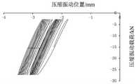
图8是本发明实施例一在浮管上施加上下振动力时获得的压缩振动位置与压缩振动载荷之间的曲线图;Fig. 8 is a curve diagram between the compressive vibration position and the compressive vibration load obtained when the vertical vibration force is applied to the floating pipe according to
图9是在浮管内中间区域增加一个竖梁后再经本发明对浮管上施加载荷力进行试验获得的压缩位移与压缩载荷之间的曲线图;Fig. 9 is a curve diagram between the compressive displacement and the compressive load obtained after the present invention applies load force on the floating tube after adding a vertical beam in the middle area of the floating tube;
图10是本发明实施例二的施力架的结构示意图。Fig. 10 is a schematic structural view of the force applying frame according to the second embodiment of the present invention.
图中附图标记含义:Meanings of reference signs in the figure:
1-防护架;1.1-边框滑槽;1.2-水平工作面;1.3-实验空间;1.4-固定螺纹孔;2-气缸;2.1-下活动端;3-力学传感器;4-前后滑动滚轮;5-横梁;5.1-横梁滑槽;5.2-横梁锁定板;6-左右滑动滚轮;7-防护网;8-固定架;8.1-固定架的下边框;8.2-固定槽;9-脚轮;10-固定脚;11-压杆;12-计算机;13-压缩机;14-气路;15-电源开关;16-下移动开关;17-上移动开关;18-浮管;19-工字架;20-横梁锁定螺栓;21-气缸锁定螺栓;22-施力架;23-固定环。1-protective frame; 1.1-frame chute; 1.2-horizontal working surface; 1.3-experimental space; 1.4-fixed threaded hole; 2-cylinder; 2.1-lower movable end; 3-mechanical sensor; -beam; 5.1-beam chute; 5.2-beam locking plate; 6-left and right sliding rollers; 7-protective net; Fixed foot; 11-pressure rod; 12-computer; 13-compressor; 14-air circuit; 15-power switch; 16-downward moving switch; 17-upward moving switch; 18-floating pipe; 20-beam locking bolt; 21-cylinder locking bolt; 22-force frame; 23-fixing ring.
具体实施方式Detailed ways
下面结合实施例对本发明进一步描述。The present invention is further described below in conjunction with embodiment.
实施例一:Embodiment one:
如图1所示为实施例一的用于测试深水网箱浮架结构力学性能的试验设备,其包括防护架1、升降施力装置、力学传感器3、施力架22、夹具架、横梁5和计算机12。As shown in Figure 1, it is the test equipment for testing the mechanical properties of the floating frame structure of the deep-water net cage of embodiment one, which includes a
防护架1为由铝型材和紧固螺丝连接而成的立方体架,底下设有脚轮9和固定脚10,脚轮9方便了防护架1的移动,固定脚10在需要固定时降下支撑在地面上。防护架1内部位实验空间1.3,正面为敞口,其余三面设有防护网7,防护网7保证了试验时的安全。The
实验空间1.3的内底面由底板铺设而成,形成水平工作面1.2,水平工作面1.2与地面具有一定距离,夹具架固定设在水平工作面1.2上,且夹具架8的位置可调节,夹具架8用于固定待测试包含有工字架19与浮管18的浮架结构的两端。夹具架包括两个固定架8,具体固定结构为:在水平工作面1.2上设有若干个固定螺纹孔1.4,固定螺纹孔1.4按矩阵排列,在水平工作面1.2上面对应每个固定架8分别设有六个压杆11,压杆11通过固定螺栓固定在固定螺纹孔1.4上,压杆11的一端部压在固定架8的下边框8.1上,通过将压杆11固定在不同的螺纹孔上,即可将固定架8固定在不同的位置,从而适应不同大小规格的浮架结构。如图3所示,在固定架8上设有固定槽8.2,在固定槽8.2两边设有固定环23,浮管18的端部通过绳索或夹具固定在固定槽8.2中,绳索或夹具的两端可绑在固定环23上。The inner bottom surface of the experimental space 1.3 is laid by the bottom plate to form a horizontal working surface 1.2. The horizontal working surface 1.2 has a certain distance from the ground. The fixture frame is fixed on the horizontal working surface 1.2, and the position of the
如图1和图2所示,横梁5的两端分别设有垂直方向的三个前后滑动滚轮4和水平方向的两个前后滑动滚轮4,在防护架1的两条上边框的上表面和内侧面分别对应设有边框滑槽1.1,前后滑动滚轮4对应配合装在边框滑槽1.1上,从而使得横梁5可前后滑动,在横梁5的两端的下边设有横梁锁定板5.2,横梁锁定板5.2位于防护架1的上边框的下方,在横梁锁定板5.2上螺纹连接有横梁锁定螺栓20,在需要固定横梁5时,向上拧紧横梁锁定螺栓20,即可锁定横梁5。As shown in Figures 1 and 2, the two ends of the
本实施例的升降施力装置包括气缸2,当然,对应气缸2会设有压缩机13、连接压缩机13与气缸2的气路14。气缸2竖直向下且可左右调节的安装在防护架1的上端,具体安装结构为:如图2所示,横梁5的中间设有横向的滑动空间,气缸2的上部穿过滑动空间,在气缸2的上部设有四个左右滑动滚轮6,四个左右滑动滚轮6两两分布在前后侧,并位于横梁5的上方,在横梁5的上边分别对应前后侧的左右滑动滚轮6设有横向的横梁滑槽5.1,左右滑动滚轮6对应安装在横梁滑槽5.1上,从而实现气缸2的左右滑动调节。在气缸2的上部还设有气缸锁定板,气缸锁定板位于横梁5的下方,在气缸锁定板上螺纹连接有气缸锁定螺栓21,在需要固定气缸2时,向上拧紧气缸锁定螺栓21,即可锁定气缸2。The lifting force application device of this embodiment includes a
本实施例通过横梁5、前后滑动滚轮4和左右滑动滚轮6实现了气缸2的可前后左右调节设置。In this embodiment, the
施力架22为横向的长方形架,施力架22的中部与气缸2的下活动端2.1连接,由气缸2带动施力架22作升降运动。力学传感器3设在施力架22与气缸的下活动端2.1之间,用于测得作用在施力架22上的力。The force-applying
力学传感器3与计算机12电性连接,计算机12接收力学传感器3输出的载荷信号。在气缸2中会配有位移传感器,为常规配置,与计算机12电性连接,计算机12还接收气缸2的升降位移信号。The
本实施例对于气缸2的控制,设有用于控制其启动的电源开关15、用于控制其下降的下移动开关16和用于控制其上升的上移动开关17,电源开关15分别与下移动开关16和上移动开关17相关联设置,只有同时接通电源开关15和下移动开关16才能控制气缸2下降,只有同时接通电源开关15和上移动开关17才能控制气缸2上升,从而保证了操作时的安全。接通电源开关15,当长时间按下移动开关16或上移动开关17时,气缸2为持续下降或上升,当点动按下移动开关16或上移动开关17时,气缸2为间断性下降或上升。For the control of the
如图1和图3所示,本实施例对包含有两条浮管18和两个工字架19的浮架结构进行试验,其中浮管18的材料为高密度聚乙烯(HDPE),两个工字架19分别联接两条浮管18的两端部,试验时调节两个固定架8的位置,将两条浮管18的两端分别固定在两个固定架8上。As shown in Fig. 1 and Fig. 3, present embodiment tests the floating frame structure that comprises two floating
通过前后调节横梁5,左右调节气缸2,使得施力架22位于其中一个工字架19的上方,锁定横梁5和气缸2,控制气缸2下降即可对工字架19位置施加向下的载荷力。通过前后调节横梁5,左右调节气缸2,使得施力架22位于浮管18的上方,控制气缸2下降即可对浮管18位置施加向下的载荷力。将施力架22下降至浮架结构的下方,调节施力架22至工字架19的下方或者浮管18的下方,控制气缸2上升,即可对工字架19或者浮管18施加向上的载荷力。在工字架19下降至浮架结构的下方进行试验时,也可通过控制气缸2上下循环运动,从而施加上下振动力,进行疲劳试验。通过上述过程即可对浮架结构的力学性能进行测试。By adjusting the
浮架结构为两端固定,试验时可为三点受力,在通过施力架22施加向下的载荷力时为对浮架结构进行弯曲受力试验,是浮架结构在深海使用过程中最容易受到的破坏力,可模拟强台风环境下系泊力对浮架结构的破坏情况。在通过施力架22施加向上的载荷力时为对浮架结构进行拉伸试验。The floating frame structure is fixed at both ends, and it can be stressed at three points during the test. When the downward load force is applied through the
在锚绳系泊及波浪载荷作用下,网箱浮架结构主要承受弯曲载荷,弯曲载荷对海上作业浮架破坏损伤为最主要影响因素,本实施例实现了在实验室1:1模拟网箱浮架结构的受力及破坏过程,可以真实反映波浪作业环境时系泊载荷的工字架与浮管联接结构的极限强度。Under the action of anchor rope mooring and wave load, the cage floating frame structure mainly bears the bending load, and the bending load is the most important factor affecting the damage of the offshore floating frame. This embodiment realizes the 1:1 simulation of the cage in the laboratory. The stress and failure process of the floating frame structure can truly reflect the ultimate strength of the connection structure between the I-frame and the floating pipe under the mooring load in the wave operation environment.
本试验设备受力方式灵活,方便改变网箱浮架试样的位置,可更改为压缩工字架试验,模拟在工字架处系泊对网箱浮架结构的作用。The force mode of this test equipment is flexible, and it is convenient to change the position of the sample of the cage floating frame. It can be changed to a compression I-shaped frame test to simulate the effect of mooring at the I-shaped frame on the structure of the floating frame of the cage.
通过对安装有不同数量或者不同间距的工字架19的浮架结构分别开展试验,可精确研究工字架19对浮架结构的保护作用。The protective effect of the I-shaped
同理可对包含有焊接的浮管18的浮架结构进行试验,对焊接位置施加载荷力,从而试验焊接的浮架结构力学性能。In the same way, the test can be carried out on the floating frame structure including the welded floating
由于夹具架8和气缸2均可调节,可对不同管径和壁厚的浮管18的浮架结构开展试验。Since both the
在试验中,持续的施加载荷力,浮架结构会由弹性形变转为塑性形变,浮管18与工字架19的联接位置会出现断裂现象,此破坏过程与波浪较大时,锚泊处承受最大载荷从而引起网箱浮架结构失效的过程一致,从而通过简化的方法直观、准确分析了网箱浮架结构承受极端海况条件下的破坏过程。试验中通过摄像机或人眼观察,当浮架结构出现明显的屈服或断裂时停止试验,通过传感器获得的数据,获得力、位移和时间之间的关系及曲线图。In the test, when the load is continuously applied, the structure of the floating frame will change from elastic deformation to plastic deformation, and the connection position between the floating
HDPE材质的网箱浮架结构在不同关键结构的屈服断裂规律如图4-图8所示,其为试验获得的压缩力上的曲线图,可对这样的曲线图进行浮架结构的力学性能分析。当然,也可以获得拉伸力上的曲线图,也可以进行浮架结构的力学性能的分析。The yield and fracture laws of the cage floating frame structure made of HDPE in different key structures are shown in Figures 4-8, which are curves obtained from the test on the compression force, and the mechanical properties of the floating frame structure can be calculated from such curves. analyze. Of course, the graph on the tensile force can also be obtained, and the mechanical performance analysis of the floating frame structure can also be performed.
如图4所示为本实施例直接在浮管上施加载荷力进行试验时获得的压缩位移与压缩载荷之间的曲线图,如图5所示为本实施例在浮管上施加载荷力进行试验时获得的压缩应力与压缩应变之间的曲线图。从两图中可以得到浮架结构用特定规格浮管试验时,随着压缩位移的不断增大,压缩载荷先按一定比例增加,随后增速减小,达到最大值后逐渐减小,此曲线反映了浮架结构上的浮管依次由弹性变形、达到屈服应力、应力强化、塑性拉伸,最后断裂失效的详细过程。As shown in Figure 4, it is the curve diagram between the compression displacement and the compressive load obtained when the present embodiment directly applies the load force on the floating tube for testing, and as shown in Figure 5, it is carried out by applying the load force on the floating tube in the present embodiment. A graph of compressive stress versus compressive strain obtained during testing. From the two figures, it can be obtained that when the floating frame structure is tested with a specific specification floating tube, as the compression displacement increases, the compression load first increases in a certain proportion, then the speed decreases, and then gradually decreases after reaching the maximum value. It reflects the detailed process of the floating tube on the floating frame structure from elastic deformation to yield stress, stress strengthening, plastic stretching, and finally fracture and failure.
同理,以下图同样看出浮架结构其他关键部件的破坏过程,各部件破坏规律主要包括弹性阶段、达到屈服强度、应力软化、应力强化、塑性伸长、断裂。但破坏过程有所不同,以判定各部件的力学性能。Similarly, the following figure also shows the failure process of other key components of the floating frame structure. The failure law of each component mainly includes the elastic stage, reaching yield strength, stress softening, stress strengthening, plastic elongation, and fracture. However, the failure process is different to determine the mechanical properties of each component.
如图6所示为本实施例在工字架上施加载荷力进行试验时获得的压缩应力与压缩应变之间的曲线图,与图5、图7相比较,在塑性变形至断裂阶段,断裂伸长率明显增大。As shown in Figure 6, it is the curve diagram between the compressive stress and the compressive strain obtained when the load force is applied on the I-shaped frame for the test in this embodiment. Compared with Figure 5 and Figure 7, in the stage of plastic deformation to fracture, the fracture The elongation was significantly increased.
如图7所示为本实施例在焊接的浮管上施加载荷力进行试验时获得的压缩应力与压缩应变之间的曲线图,从图7可以看出,焊接的浮管的强度明显小于网箱母管材,焊接的浮管的断裂伸长率也小于母管材,说明焊接的浮管的韧性降低。浮架结构的焊接浮管的断裂伸长率、屈服强度皆小于母管材,而弹性模量较大,为网箱浮架作业危险区域之一,由此可给出网箱浮架优化意见,减少焊接接头。As shown in Figure 7, it is the curve diagram between the compressive stress and the compressive strain obtained when the load force is applied on the welded floating tube in this embodiment, as can be seen from Figure 7, the intensity of the welded floating tube is obviously smaller than that of the net The elongation at break of the welded floating tube is also smaller than that of the parent tube, indicating that the toughness of the welded floating tube is reduced. The elongation at break and yield strength of the welded floating pipe of the floating frame structure are smaller than the parent pipe, but the elastic modulus is relatively large, which is one of the dangerous areas of the floating frame of the net cage. From this, optimization suggestions for the floating frame of the net cage can be given. Reduce welded joints.
根据长期波浪动态载荷对网箱的振动疲劳作用过程,网箱浮架结构与锚泊、网衣由于波浪作用相互接触或分离时发生刚度突变而导致受力状态不断变化,网箱浮架结构主要承受弯曲载荷而呈往复振动,弯曲后的浮架结构外侧受到交变压缩力,与试验过程的受力形式相同。如图8所示为本实施例在浮管上施加上下振动力时获得的压缩振动位置与压缩振动载荷之间的曲线图,测定交变载荷条件下浮架结构的疲劳响应,可依此确定浮架结构长期在海况条件下的承载失效情况。按照指定的振幅及频率,通过振动试验可以获得网箱浮架结构的疲劳老化性能。为长期承受极限波浪及系泊环境下网箱结构的优化设计提供试验支撑。According to the long-term wave dynamic load on the vibration fatigue process of the cage, the stiffness of the cage floating frame structure, mooring, and netting due to wave action will change when the stiffness changes, resulting in continuous changes in the stress state. The cage floating frame structure mainly bears Bending load causes reciprocating vibration, and the outside of the bent floating frame structure is subjected to alternating compression force, which is the same as the force form during the test. As shown in Fig. 8, it is a curve diagram between the compression vibration position and the compression vibration load obtained when the vertical vibration force is applied on the floating tube in this embodiment, and the fatigue response of the floating frame structure under the condition of alternating load is measured, and the floating structure can be determined accordingly. The load-bearing failure of the frame structure under sea conditions for a long time. According to the specified amplitude and frequency, the fatigue aging performance of the cage floating frame structure can be obtained through the vibration test. Provide experimental support for the optimal design of the cage structure under long-term extreme waves and mooring environments.
根据以上图的力学性能测试结果,可对浮架结构进行优化设计并对比试验,在浮管内中间区域增加一个竖梁,并获得了对应如图9所示的力学性能,最大拉力增大,表明强度增大。According to the test results of the mechanical properties in the above figure, the structure of the floating frame can be optimized and tested by comparison. A vertical beam is added in the middle area of the floating tube, and the corresponding mechanical properties are obtained as shown in Figure 9. The maximum tensile force increases, indicating that Increased strength.
实施例二:Embodiment two:
实施例二的试验设备与实施例的不同在于施力架22,如图10所示为实施例二的施力架22,其更换为圆形架,通过更换为圆形的施力架22可以调整对网箱浮架结构的受力面积和形式。The difference between the test equipment of embodiment two and the embodiment is that the
当然,施力架22的形状结构也可以为其它能对浮架结构进行施力的结构。Of course, the shape and structure of the
本发明的上述实施例并不是对本发明保护范围的限定,本发明的实施方式不限于此,凡此种种根据本发明的上述内容,按照本领域的普通技术知识和惯用手段,在不脱离本发明上述基本技术思想前提下,对本发明上述结构做出的其它多种形式的修改、替换或变更,均应落在本发明的保护范围之内。The above-mentioned embodiments of the present invention do not limit the protection scope of the present invention. Under the premise of the above-mentioned basic technical ideas, other modifications, replacements or changes made to the above-mentioned structures of the present invention in various forms shall fall within the protection scope of the present invention.
Claims (5)
Priority Applications (1)
| Application Number | Priority Date | Filing Date | Title |
|---|---|---|---|
| CN202010405276.3ACN111579227B (en) | 2020-05-13 | 2020-05-13 | A test equipment for testing the mechanical properties of deep-water cage floating frame structures |
Applications Claiming Priority (1)
| Application Number | Priority Date | Filing Date | Title |
|---|---|---|---|
| CN202010405276.3ACN111579227B (en) | 2020-05-13 | 2020-05-13 | A test equipment for testing the mechanical properties of deep-water cage floating frame structures |
Publications (2)
| Publication Number | Publication Date |
|---|---|
| CN111579227A CN111579227A (en) | 2020-08-25 |
| CN111579227Btrue CN111579227B (en) | 2022-11-11 |
Family
ID=72124957
Family Applications (1)
| Application Number | Title | Priority Date | Filing Date |
|---|---|---|---|
| CN202010405276.3AExpired - Fee RelatedCN111579227B (en) | 2020-05-13 | 2020-05-13 | A test equipment for testing the mechanical properties of deep-water cage floating frame structures |
Country Status (1)
| Country | Link |
|---|---|
| CN (1) | CN111579227B (en) |
Families Citing this family (4)
| Publication number | Priority date | Publication date | Assignee | Title |
|---|---|---|---|---|
| CN112903243B (en)* | 2021-01-25 | 2022-04-15 | 浙江大学 | A method of cage state detection based on modal analysis in marine environment |
| CN112772501A (en)* | 2021-02-01 | 2021-05-11 | 海南昌江元道养殖有限公司 | Deep-sea net cage for golden pomfret culture and use method thereof |
| CN113925007B (en)* | 2021-10-29 | 2023-10-17 | 山东大学 | Gravity type net cage design method based on balance weight and cable distribution evaluation |
| CN116046545A (en)* | 2022-11-21 | 2023-05-02 | 四川玄武岩纤维新材料研究院(创新中心) | Static Test Method for Large Composite Cages |
Family Cites Families (19)
| Publication number | Priority date | Publication date | Assignee | Title |
|---|---|---|---|---|
| JPH10267812A (en)* | 1997-03-28 | 1998-10-09 | Ishikawajima Harima Heavy Ind Co Ltd | Pipe four-point bending test equipment |
| CN101135886A (en)* | 2007-08-31 | 2008-03-05 | 无锡华科机械设备有限公司 | Hanging cradle controller for construction using single-phase electric power |
| CN102116720B (en)* | 2010-01-04 | 2013-02-27 | 中国科学院地质与地球物理研究所 | Frequency-variable-amplitude dynamic loading rock mechanics test system |
| CN101907547A (en)* | 2010-07-05 | 2010-12-08 | 清华大学 | Biaxial Compression Test Equipment |
| CN102109443B (en)* | 2010-12-24 | 2012-07-25 | 同济大学 | High-accuracy hydraulic repeated loading test device |
| CN102175513B (en)* | 2011-01-14 | 2012-11-14 | 天津大学 | Separable type deepwater seabed pipeline bending test system |
| CN102426133B (en)* | 2011-09-08 | 2013-08-21 | 湖南大学 | Device and method for loading axial forces and side forces onto structural member |
| CN104422614A (en)* | 2013-08-20 | 2015-03-18 | 天津市港石密封机械有限公司 | Pipeline external pressure test device |
| CN103512805B (en)* | 2013-10-22 | 2015-12-30 | 安徽理工大学 | A kind of pressue device of simulating the anchor rod drawing experiment of anchoring body surrouding rock stress |
| CN104455744B (en)* | 2014-11-28 | 2016-12-28 | 赵汝春 | Petroleum pipeline bracing frame |
| CN104535433A (en)* | 2014-12-31 | 2015-04-22 | 中国石油天然气集团公司 | Full-size pipeline fatigue test operating platform |
| CN106610359A (en)* | 2015-10-23 | 2017-05-03 | 宝鸡石油钢管有限责任公司 | Four-point bending test device for pipe full-size evaluation |
| CN105252309A (en)* | 2015-11-16 | 2016-01-20 | 哈尔滨工业大学 | Clamp for water jet cutter to machine railway wagon swing bolster casting |
| CN105666187B (en)* | 2016-04-07 | 2017-08-25 | 镇江远大传动机械有限公司 | The clamping device processed based on machining center to engaging lug internal face on weld yoke |
| CN207074143U (en)* | 2017-04-01 | 2018-03-06 | 山东省产品质量检验研究院 | A kind of fire-fighting carries torque automatic test equipment with plough groove type pipe joint |
| CN207991972U (en)* | 2018-02-27 | 2018-10-19 | 江西鸿基管桩有限公司 | A kind of pile pile beam test device of real time monitoring |
| CN208214870U (en)* | 2018-05-10 | 2018-12-11 | 中山市欧楷照明科技有限公司 | A detachable clamp assembly |
| CN209919370U (en)* | 2019-04-25 | 2020-01-10 | 江苏国协机械科技有限公司 | Multi-process machining clamping tool for workpiece |
| CN110411867B (en)* | 2019-08-02 | 2022-02-22 | 郑州大学 | Novel multifunctional impact fracture test device and use method |
- 2020
- 2020-05-13CNCN202010405276.3Apatent/CN111579227B/ennot_activeExpired - Fee Related
Also Published As
| Publication number | Publication date |
|---|---|
| CN111579227A (en) | 2020-08-25 |
Similar Documents
| Publication | Publication Date | Title |
|---|---|---|
| CN111579227B (en) | A test equipment for testing the mechanical properties of deep-water cage floating frame structures | |
| CN109283047B (en) | Rock mass damage monitoring system and evaluation method in deep engineering environment | |
| Dolce et al. | Shaking table tests on reinforced concrete frames without and with passive control systems | |
| JP6165838B2 (en) | Large deformation tensile test system | |
| CN102081014B (en) | Comprehensive performance test bed of automobile shock absorber | |
| Li et al. | Behavior of connections between square CFST columns and H-section steel beams | |
| CN102607840B (en) | Large deformation tensile force testing system | |
| CN112665994B (en) | Gravity unloading rock mass dynamic unloading test system and method | |
| Cao et al. | Experimental seismic behaviour of bottom-through-diaphragm and top-ring connection to SST columns | |
| Feng et al. | Novel joint for pultruded FRP beams and concrete-filled FRP columns: Conceptual and experimental investigations | |
| CN106323751A (en) | Multiaxial pulling-pressing loading system for testing mechanical properties of defective materials with cracks | |
| CN113340747A (en) | Anchor rod shearing testing device and method | |
| Yan et al. | Experimental and numerical study on the dynamic behavior of concrete-filled double steel tubular T-joint under impact loading | |
| Liu et al. | Seismic performance of irregular-shaped concrete-filled steel tube column to H-shaped steel beam joints with inner semi-diaphragm: experimental and numerical study | |
| CN115931320B (en) | A device and method for testing the ultimate strength of a ship box beam model | |
| Shrestha et al. | Strengthening RC beam–column connections with FRP strips | |
| Liu et al. | Experimental and numerical study on the penetration of the inclined stiffened plate | |
| Nguyen et al. | Experimental investigation of long-span cold-rolled aluminium built-up section portal frames: unbraced columns and flexural-torsional buckling | |
| CN107179242B (en) | A kind of manual simplified true triaxil tester | |
| Rong et al. | Flexural bearing capacity of diaphragm-through joints of concrete-filled square steel tubular columns | |
| Zhao et al. | Experimental study and numerical analysis on the dynamic response of steel tube confined concrete with a circular hollow section (STCC-CHS) under transverse impact loading | |
| CN201285275Y (en) | Residual deformation measuring apparatus used for reinforced bar mechanical connector type inspection | |
| CN110220782A (en) | A kind of can ice Mechanics Performance Testing device | |
| Zhang et al. | Static performance of slidable bolt-assembly truss-to-column connection with oversized bolt holes | |
| CN2839431Y (en) | Carbon fiber cloth reinforced beam stretch-draw anchoring mechanism |
Legal Events
| Date | Code | Title | Description |
|---|---|---|---|
| PB01 | Publication | ||
| PB01 | Publication | ||
| SE01 | Entry into force of request for substantive examination | ||
| SE01 | Entry into force of request for substantive examination | ||
| TA01 | Transfer of patent application right | Effective date of registration:20221019 Address after:100084 Tsinghua Yuan, Beijing, Haidian District Applicant after:TSINGHUA University Applicant after:Sanya tropical Fisheries Research Institute Applicant after:SOUTH CHINA SEA FISHERIES Research Institute CHINESE ACADEMY OF FISHERY SCIENCES Address before:510300 No. 231 West Xingang Road, Guangzhou, Guangdong, Haizhuqu District Applicant before:SOUTH CHINA SEA FISHERIES Research Institute CHINESE ACADEMY OF FISHERY SCIENCES | |
| TA01 | Transfer of patent application right | ||
| GR01 | Patent grant | ||
| GR01 | Patent grant | ||
| CF01 | Termination of patent right due to non-payment of annual fee | Granted publication date:20221111 | |
| CF01 | Termination of patent right due to non-payment of annual fee |