CN111578923A - Closed-loop control method and system for resonant gyroscope - Google Patents
Closed-loop control method and system for resonant gyroscopeDownload PDFInfo
- Publication number
- CN111578923A CN111578923ACN202010416651.4ACN202010416651ACN111578923ACN 111578923 ACN111578923 ACN 111578923ACN 202010416651 ACN202010416651 ACN 202010416651ACN 111578923 ACN111578923 ACN 111578923A
- Authority
- CN
- China
- Prior art keywords
- signal
- loop
- amplitude
- input
- quadrature
- Prior art date
- Legal status (The legal status is an assumption and is not a legal conclusion. Google has not performed a legal analysis and makes no representation as to the accuracy of the status listed.)
- Granted
Links
Images


Classifications
- G—PHYSICS
- G01—MEASURING; TESTING
- G01C—MEASURING DISTANCES, LEVELS OR BEARINGS; SURVEYING; NAVIGATION; GYROSCOPIC INSTRUMENTS; PHOTOGRAMMETRY OR VIDEOGRAMMETRY
- G01C19/00—Gyroscopes; Turn-sensitive devices using vibrating masses; Turn-sensitive devices without moving masses; Measuring angular rate using gyroscopic effects
- G01C19/56—Turn-sensitive devices using vibrating masses, e.g. vibratory angular rate sensors based on Coriolis forces
- G01C19/5719—Turn-sensitive devices using vibrating masses, e.g. vibratory angular rate sensors based on Coriolis forces using planar vibrating masses driven in a translation vibration along an axis
- G—PHYSICS
- G01—MEASURING; TESTING
- G01C—MEASURING DISTANCES, LEVELS OR BEARINGS; SURVEYING; NAVIGATION; GYROSCOPIC INSTRUMENTS; PHOTOGRAMMETRY OR VIDEOGRAMMETRY
- G01C25/00—Manufacturing, calibrating, cleaning, or repairing instruments or devices referred to in the other groups of this subclass
- G01C25/005—Manufacturing, calibrating, cleaning, or repairing instruments or devices referred to in the other groups of this subclass initial alignment, calibration or starting-up of inertial devices
Landscapes
- Engineering & Computer Science (AREA)
- Physics & Mathematics (AREA)
- General Physics & Mathematics (AREA)
- Radar, Positioning & Navigation (AREA)
- Remote Sensing (AREA)
- Manufacturing & Machinery (AREA)
- Gyroscopes (AREA)
Abstract
Translated fromChinese
Description
Translated fromChinese技术领域technical field
本发明涉及谐振式陀螺仪技术领域,具体是一种微机电系统(MEMS,Micro-Electro-Mechanical System)谐振式陀螺闭环控制方法与系统。The invention relates to the technical field of resonant gyroscopes, in particular to a micro-electromechanical system (MEMS, Micro-Electro-Mechanical System) resonant gyroscope closed-loop control method and system.
背景技术Background technique
陀螺仪是测量载体相对惯性空间旋转运动的传感器,是航空航天、卫星导航、远洋潜航、姿态测量等领域的核心器件,在航空航天、智能机器人、制导弹药等高端工业装备和精确打击武器中具有非常重要的应用价值。传统的陀螺仪包括机械转子陀螺、静电陀螺、半球谐振陀螺、激光陀螺、光纤陀螺等,它们精度普遍较高,但同时具有体积大、功耗高、价格高等缺点,越来越难以适应信息化时代对于小体积和低功耗的需求。基于微机电系统技术的MEMS陀螺仪具有体积小、功耗低、寿命长、可批量生产、价格便宜等诸多特点,在大批量和小体积的工业和武器装备应用中具有先天优势。但与传统陀螺仪相比,目前MEMS陀螺仪的精度还不够高,应用主要局限于智能手机、微型无人机、汽车稳定控制系统等低端领域。卫星导航抗干扰抗欺骗、室内导航、微小型水下无人平台、单兵定位、地下随钻定向系统等新兴领域对高性能、小体积、低功耗、低成本MEMS陀螺仪提出了迫切需求。A gyroscope is a sensor that measures the relative inertial space rotation of a carrier. It is a core device in the fields of aerospace, satellite navigation, ocean diving, and attitude measurement. It has high-end industrial equipment and precision strike weapons in aerospace, intelligent robots, and guided munitions. very important application value. Traditional gyroscopes include mechanical rotor gyroscopes, electrostatic gyroscopes, hemispherical resonant gyroscopes, laser gyroscopes, fiber optic gyroscopes, etc. They are generally of high accuracy, but at the same time have the disadvantages of large size, high power consumption, and high price, making it more and more difficult to adapt to informatization. The needs of the times for small size and low power consumption. MEMS gyroscopes based on microelectromechanical system technology have many characteristics such as small size, low power consumption, long life, mass production, and low price. They have inherent advantages in large-scale and small-volume industrial and weapon equipment applications. However, compared with traditional gyroscopes, the accuracy of MEMS gyroscopes is not high enough at present, and their applications are mainly limited to low-end fields such as smart phones, micro drones, and automotive stability control systems. Emerging fields such as satellite navigation anti-jamming and anti-spoofing, indoor navigation, micro-small underwater unmanned platforms, individual soldier positioning, and underground directional-while-drilling systems have put forward urgent needs for high-performance, small-volume, low-power, and low-cost MEMS gyroscopes. .
标度因数是指陀螺输出数据与输入角速度之间的比值,即单位角速度输入对应陀螺输出值的大小。对于谐振式微机械陀螺而言,无论是开环控制模式还是力平衡闭环控制控制,外界环境因素(尤其是温度)的变化均会对标度因数的大小产生很严重的影响,导致标度因数的稳定性和重复性变差。对于高精度导航系统而言,标度因数的不稳定性会造成极大的累积误差,限制陀螺精度水平的发挥。传统的标度因数控制方法主要是基于标度因数和各系统参数随环境变化的测试数据进行的拟合补偿法,需要进行大量的前期数据测试来确定拟合补偿函数,同时需要陀螺保持良好的稳定性才能保证整体的补偿精度。这样的方法不但耗时耗力,而且难以适用于状态可能发生变化的陀螺。因此,研究陀螺标度因数的闭环方法,对提高标度因数的稳定性具有重要的意义和价值。The scale factor refers to the ratio between the gyro output data and the input angular velocity, that is, the magnitude of the gyro output value corresponding to the unit angular velocity input. For resonant micromachined gyroscopes, whether it is an open-loop control mode or a force-balanced closed-loop control, changes in external environmental factors (especially temperature) will have a serious impact on the size of the scale factor, resulting in the increase of the scale factor. Stability and repeatability deteriorate. For a high-precision navigation system, the instability of the scale factor will cause a huge cumulative error, which limits the performance of the gyro's accuracy level. The traditional scale factor control method is mainly based on the scale factor and the test data of the system parameters changing with the environment. Only stability can ensure the overall compensation accuracy. Such a method is not only time-consuming and labor-intensive, but also difficult to apply to a gyroscope whose state may change. Therefore, it is of great significance and value to study the closed-loop method of the gyro scale factor to improve the stability of the scale factor.
发明内容SUMMARY OF THE INVENTION
本发明提供一种谐振式陀螺闭环控制方法、系统及陀螺仪,用于克服现有技术中对陀螺的稳定性要求较高导致适应性较差、需要大量前期数据导致耗时费力等缺陷,通过闭环控制,在状态变化过程中对陀螺标度因数进行自动补偿,将标度因数稳定在较高值附近,以提高陀螺在运行状态下标度因数的稳定性。The present invention provides a closed-loop control method, system and gyroscope of a resonant gyroscope, which are used to overcome the defects of the prior art, such as poor adaptability due to high requirements on the stability of gyroscopes, time-consuming and labor-intensive due to the need for a large amount of preliminary data, and the like. The closed-loop control automatically compensates the scale factor of the gyro during the state change, and stabilizes the scale factor near a higher value to improve the stability of the scale factor in the running state of the gyro.
为实现上述目的,本发明提供一种谐振式陀螺闭环控制方法,包括以下步骤:In order to achieve the above object, the present invention provides a resonant gyro closed-loop control method, comprising the following steps:
步骤1,驱动模态下,采集表征陀螺仪驱动方向振动位移的第一信号输入驱动环路;检测模态下,采集表征陀螺仪检测方向振动位移的第二信号输入检测环路;Step 1: In the driving mode, a first signal representing the vibration displacement in the driving direction of the gyroscope is collected and input into the driving loop; in the detection mode, the second signal representing the vibration displacement in the detection direction of the gyroscope is collected and input into the detection loop;
步骤2,第一信号经转换和解调、闭环控制、调制生成驱动控制信号输入驱动电极以激励谐振子在驱动方向恒幅振动;
第二信号分成两路,一路经正交解调、处理后生成控制信号输入正交误差修调电极以抑制正交误差信号;另一路经力平衡环路解调、处理后生成角速度检测信号即陀螺输出信号,将陀螺输出信号与校正解调信号叠加得到带扰动的反馈力信号;The second signal is divided into two paths, one of which is quadrature demodulated and processed to generate a control signal and input to the quadrature error trimming electrode to suppress the quadrature error signal; the other is demodulated and processed by the force balance loop to generate an angular velocity detection signal, namely Gyro output signal, superimpose the gyro output signal and the correction demodulation signal to obtain the feedback force signal with disturbance;
步骤3,对经正交误差抑制环路解调后的信号及经力平衡环路解调后的信号分别进行信号解调和幅值提取运算;对所述幅值进行运算获得标度补偿信号;将角速度检测信号与所述校正解调信号叠加后与标度补偿信号进行幅值运算,得到的信号输入检测电极中,标度补偿信号的大小控制带扰动反馈力信号的幅值,以实现对陀螺仪的标度因数自动补偿。
为实现上述目的,本发明还提供一种谐振式陀螺闭环控制系统,包括:To achieve the above object, the present invention also provides a resonant gyro closed-loop control system, comprising:
驱动环路,用于在驱动模态下,对输入的第一信号进行转换和解调、闭环控制、调制,最终生成驱动控制信号输入驱动电极,以激励谐振子在驱动方向恒幅振动;所述第一信号用于表征陀螺仪驱动方向的振动位移;The driving loop is used to convert and demodulate, close-loop control, and modulate the input first signal in the driving mode, and finally generate a driving control signal and input it to the driving electrode to excite the resonator to vibrate with constant amplitude in the driving direction; The first signal is used to characterize the vibration displacement in the driving direction of the gyroscope;
检测环路,用于检测陀螺仪输入的轴向的角速度;包括:A detection loop that detects the angular velocity of the gyroscope input axis; includes:
正交误差抑制环路,用于在检测模态下,对输入的第二信号进行解调、处理生成正交控制信号输入正交误差修调电极,以抑制正交误差信号;The quadrature error suppression loop is used to demodulate and process the input second signal in the detection mode to generate a quadrature control signal and input the quadrature error modification electrode to suppress the quadrature error signal;
力平衡环路,用于在检测模态下,对输入的第二信号进行解调、处理生成角速度的检测信号,该信号输入检测电极后会产生静电力,用于抵消由输入角速度产生的哥氏力,使得谐振子在检测方向上维持静止的平衡状态;所述第二信号用于表征陀螺仪检测方向的振动位移;The force balance loop is used to demodulate and process the input second signal in the detection mode to generate the detection signal of the angular velocity. After the signal is input to the detection electrode, an electrostatic force will be generated to offset the force generated by the input angular velocity. force, so that the resonator maintains a static equilibrium state in the detection direction; the second signal is used to characterize the vibration displacement in the detection direction of the gyroscope;
标度补偿环路,用于对经正交误差抑制环路解调后的信号及经力平衡环路解调后的信号分别进行信号解调和幅值运算;对所述幅值进行以设定值为目标的PID控制运算,获得标度补偿信号;The scale compensation loop is used to perform signal demodulation and amplitude operation on the signal demodulated by the quadrature error suppression loop and the signal demodulated by the force balance loop respectively; The fixed value is the PID control operation of the target, and the scale compensation signal is obtained;
所述力平衡环路,还用于将角速度检测信号与所述校正解调信号叠加后与标度补偿信号进行幅值运算输入检测电极,以实现对陀螺仪的标度因数自动补偿。The force balance loop is also used to superimpose the angular velocity detection signal and the correction and demodulation signal, and then perform amplitude operation on the scale compensation signal and input it to the detection electrode, so as to realize automatic compensation of the scale factor of the gyroscope.
本发明提供的谐振式陀螺闭环控制方法与系统,在通过正交误差抑制环路的闭环控制和力平衡环路检测的基础上,通过标度补偿环路调整陀螺的输出从而实现对标度因数控制,补偿标度因数随环境的变化量,使系统的标度因数处于一定的稳定状态,从而在实现陀螺低噪声角速度检测的同时,保证了标度因数的稳定性。The resonant gyro closed-loop control method and system provided by the present invention are based on the closed-loop control of the quadrature error suppression loop and the detection of the force balance loop, and the output of the gyro is adjusted through the scale compensation loop to realize the adjustment of the scale factor. Control and compensate the change of the scale factor with the environment, so that the scale factor of the system is in a certain stable state, so as to realize the low-noise angular velocity detection of the gyro, and at the same time ensure the stability of the scale factor.
附图说明Description of drawings
为了更清楚地说明本发明实施例或现有技术中的技术方案,下面将对实施例或现有技术描述中所需要使用的附图作简单地介绍,显而易见地,下面描述中的附图仅仅是本发明的一些实施例,对于本领域普通技术人员来讲,在不付出创造性劳动的前提下,还可以根据这些附图示出的结构获得其他的附图。In order to explain the embodiments of the present invention or the technical solutions in the prior art more clearly, the following briefly introduces the accompanying drawings that need to be used in the description of the embodiments or the prior art. Obviously, the accompanying drawings in the following description are only These are some embodiments of the present invention, and for those of ordinary skill in the art, other drawings can also be obtained according to the structures shown in these drawings without creative efforts.
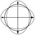
图1a为谐振式微机电陀螺简并模态中第一模态即驱动模态示意图;FIG. 1a is a schematic diagram of the first mode in the degenerate mode of the resonant MEMS gyroscope, that is, the driving mode;
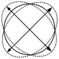
图1b为谐振式微机电陀螺简并模态中第二模态即检测模态示意图;Fig. 1b is a schematic diagram of the second mode, that is, the detection mode, in the degenerate mode of the resonant MEMS gyroscope;
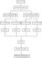
图2为本发明实施例一提供的谐振式陀螺闭环控制方法中力平衡模式角速度测量流程图;Fig. 2 is the flow chart of force balance mode angular velocity measurement in the resonant gyro closed-loop control method provided in the first embodiment of the present invention;
图3为本发明实施例一提供的谐振式陀螺闭环控制方法中标度因数补偿环路工作流程图;3 is a flow chart of a scale factor compensation loop in the resonant gyro closed-loop control method provided in
图4为本发明实施例二提供的谐振式陀螺闭环控制系统的原理框图;4 is a schematic block diagram of a resonant gyro closed-loop control system provided in
图5为标度补偿环路(标度因数控制回路)的具体结构框图;5 is a specific structural block diagram of a scale compensation loop (scale factor control loop);
图6为驱动环路的仿真结果;Fig. 6 is the simulation result of the drive loop;
图7为正交误差抑制环路的仿真结果;Fig. 7 is the simulation result of the quadrature error suppression loop;
图8为力平衡环路的仿真结果;Fig. 8 is the simulation result of the force balance loop;
图9为不同角速度下陀螺稳定状态的输出曲线图。FIG. 9 is an output curve diagram of the gyro steady state under different angular velocities.
本发明目的的实现、功能特点及优点将结合实施例,参照附图做进一步说明。The realization, functional characteristics and advantages of the present invention will be further described with reference to the accompanying drawings in conjunction with the embodiments.
具体实施方式Detailed ways
下面将结合本发明实施例中的附图,对本发明实施例中的技术方案进行清楚、完整地描述,显然,所描述的实施例仅仅是本发明的一部分实施例,而不是全部的实施例。基于本发明中的实施例,本领域普通技术人员在没有作出创造性劳动前提下所获得的所有其他实施例,都属于本发明保护的范围。The technical solutions in the embodiments of the present invention will be clearly and completely described below with reference to the accompanying drawings in the embodiments of the present invention. Obviously, the described embodiments are only a part of the embodiments of the present invention, not all of the embodiments. Based on the embodiments of the present invention, all other embodiments obtained by those of ordinary skill in the art without creative efforts shall fall within the protection scope of the present invention.
需要说明,本发明实施例中所有方向性指示(诸如上、下、左、右、前、后......)仅用于解释在某一特定姿态(如附图所示)下各部件之间的相对位置关系、运动情况等,如果该特定姿态发生改变时,则该方向性指示也相应地随之改变。It should be noted that all directional indications (such as up, down, left, right, front, back...) in the embodiments of the present invention are only used to explain the The relative positional relationship between the components, the movement situation, etc., if the specific posture changes, the directional indication also changes accordingly.
另外,在本发明中如涉及“第一”、“第二”等的描述仅用于描述目的,而不能理解为指示或暗示其相对重要性或者隐含指明所指示的技术特征的数量。由此,限定有“第一”、“第二”的特征可以明示或者隐含地包括至少一个该特征。在本发明的描述中,“多个”的含义是至少两个,例如两个,三个等,除非另有明确具体的限定。In addition, descriptions such as "first", "second", etc. in the present invention are only for descriptive purposes, and should not be construed as indicating or implying their relative importance or implicitly indicating the number of indicated technical features. Thus, a feature delimited with "first", "second" may expressly or implicitly include at least one of that feature. In the description of the present invention, "plurality" means at least two, such as two, three, etc., unless otherwise expressly and specifically defined.
在本发明中,除非另有明确的规定和限定,术语“连接”、“固定”等应做广义理解,例如,“固定”可以是固定连接,也可以是可拆卸连接,或成一体;可以是机械连接,也可以是电连接,还可以是物理连接或无线通信连接;可以是直接相连,也可以通过中间媒介间接相连,可以是两个元件内部的连通或两个元件的相互作用关系,除非另有明确的限定。对于本领域的普通技术人员而言,可以根据具体情况理解上述术语在本发明中的具体含义。In the present invention, unless otherwise expressly specified and limited, the terms "connected", "fixed" and the like should be understood in a broad sense, for example, "fixed" may be a fixed connection, a detachable connection, or an integrated; It can be a mechanical connection, an electrical connection, a physical connection or a wireless communication connection; it can be a direct connection or an indirect connection through an intermediate medium, and it can be the internal connection of two elements or the interaction between the two elements. unless otherwise expressly qualified. For those of ordinary skill in the art, the specific meanings of the above terms in the present invention can be understood according to specific situations.
另外,本发明各个实施例之间的技术方案可以相互结合,但是必须是以本领域普通技术人员能够实现为基础,当技术方案的结合出现相互矛盾或无法实现时应当认为这种技术方案的结合不存在,也不在本发明要求的保护范围之内。In addition, the technical solutions between the various embodiments of the present invention can be combined with each other, but must be based on the realization by those of ordinary skill in the art. When the combination of technical solutions is contradictory or cannot be realized, it should be considered that the combination of technical solutions does not exist and is not within the scope of protection claimed by the present invention.
实施例一Example 1
如图1a、图1b、图2、图3所示,本发明实施例提供一种谐振式陀螺闭环控制方法,其特征在于,包括以下步骤:As shown in FIG. 1a, FIG. 1b, FIG. 2, and FIG. 3, an embodiment of the present invention provides a resonant gyro closed-loop control method, which is characterized in that it includes the following steps:
步骤1,驱动模态下,采集表征陀螺仪驱动方向振动位移的第一信号输入驱动环路;检测模态下,采集表征陀螺仪检测方向振动位移的第二信号输入检测环路;Step 1: In the driving mode, a first signal representing the vibration displacement in the driving direction of the gyroscope is collected and input into the driving loop; in the detection mode, the second signal representing the vibration displacement in the detection direction of the gyroscope is collected and input into the detection loop;
步骤2,第一信号经转换和解调、闭环控制、调制生成驱动控制信号输入驱动电极以激励谐振子在驱动方向恒幅振动;
第二信号分成两路,一路经正交解调、处理后生成控制信号输入正交误差修调电极以抑制正交误差信号;另一路经力平衡环路解调、处理后生成角速度检测信号即陀螺输出信号,将陀螺输出信号与一个校正解调信号叠加得到带扰动的反馈力信号;在本发明一实施例中,校正解调信号可以通过其他电路或装置从外部加载在陀螺仪上与陀螺输出信号叠加;The second signal is divided into two paths, one of which is quadrature demodulated and processed to generate a control signal and input to the quadrature error trimming electrode to suppress the quadrature error signal; the other is demodulated and processed by the force balance loop to generate an angular velocity detection signal, namely The gyro output signal is superimposed on the gyro output signal and a correction and demodulation signal to obtain a feedback force signal with disturbance; in an embodiment of the present invention, the correction and demodulation signal can be externally loaded on the gyroscope and the gyro through other circuits or devices. output signal superposition;
驱动模态参见图1a;检测模态参见图1b,步骤1、2均可采用公知技术;The driving mode is shown in Figure 1a; the detection mode is shown in Figure 1b, and both
步骤3,对经正交误差抑制环路解调后的信号及经力平衡环路解调后的信号分别进行信号解调和幅值提取运算;对所述幅值进行运算获得标度补偿信号;将角速度检测信号与所述校正解调信号叠加后与标度补偿信号进行幅值运算,得到的信号输入检测电极中,标度补偿信号的大小控制带扰动反馈力信号的幅值,以实现对陀螺仪的标度因数自动补偿。
参见图3,对上述力平衡环路输出的陀螺的轴向角速度的检测信号叠加校正解调信号,陀螺仪检测轴(参见图1b中双箭头线段)的振动响应,该信号分别进行同相和正交解调,得到的信号输入如图5所示的校正环路(虚线框内的部分)再用校正解调信号进行同相和正交解调,最后再通过乘法器和加法器实现幅值提取,从而消除了二次解调相位误差和校正解调信号解调相位误差的影响。Referring to FIG. 3 , the detection signal of the axial angular velocity of the gyroscope output by the above-mentioned force balance loop is superimposed on the correction demodulation signal, and the vibration response of the gyroscope detection axis (refer to the line segment of the double arrow in FIG. 1 b ) is in-phase and positive Inter-demodulation, the obtained signal is input to the correction loop shown in Figure 5 (the part in the dashed box), and then the correction and demodulation signal is used for in-phase and quadrature demodulation, and finally the amplitude is extracted by the multiplier and the adder. , thereby eliminating the influence of the secondary demodulation phase error and the demodulation phase error of the corrected demodulation signal.
优选地,所述步骤3包括以下步骤:Preferably, the
步骤31,处理后的第二信号经正交解调器解调后生成正交输入信号,处理后的第二信号经同相解调器解调后生成同相输入信号;Step 31, the processed second signal is demodulated by a quadrature demodulator to generate a quadrature input signal, and the processed second signal is demodulated by an in-phase demodulator to generate an in-phase input signal;
步骤32,同时输入同相解调信号及正交解调信号,分别对所述正交输入信号及同相输入信号解调后生成四个幅值;Step 32, input the in-phase demodulation signal and the quadrature demodulation signal at the same time, and generate four amplitudes after demodulating the quadrature input signal and the in-phase input signal respectively;
步骤33,对四个幅值分别进行乘法、滤波、乘法运算后求和作为最终幅值提取;Step 33, the four amplitudes are respectively multiplied, filtered, and multiplied and then summed as the final amplitude extraction;
步骤34,对所述幅值进行以预设值为目标的PID控制运算获得标度补偿信号并输出;Step 34, performing the PID control operation with the preset value as the target on the amplitude to obtain the scale compensation signal and output;
步骤35,将角速度检测信号与所述校正解调信号叠加后与标度因数补偿信号进行乘法运算输入检测电极,以实现对陀螺仪的标度因数自动补偿。Step 35: The angular velocity detection signal and the correction demodulation signal are superimposed and then multiplied with the scale factor compensation signal and input to the detection electrode, so as to realize automatic compensation of the scale factor of the gyroscope.
优选地,所述步骤32包括以下步骤:Preferably, the step 32 includes the following steps:
步骤321,同相解调信号对正交输入信号进行同相同频解调生成第一幅值;Step 321, the in-phase demodulation signal performs in-phase demodulation on the quadrature input signal to generate a first amplitude value;
步骤322,同相解调信号对同相输入信号进行同相同频解调生成第二幅值;Step 322, the in-phase demodulation signal performs the same-frequency demodulation on the in-phase input signal to generate a second amplitude value;
步骤323,正交解调信号对正交输入信号进行90度相位差同频解调生成第三幅值;Step 323, the quadrature demodulation signal performs 90-degree phase difference co-frequency demodulation on the quadrature input signal to generate a third amplitude;
步骤324,正交解调信号对同相输入信号进行90度相位差同频解调生成第四幅值。Step 324, the quadrature demodulation signal performs co-frequency demodulation with a 90-degree phase difference on the in-phase input signal to generate a fourth amplitude value.
优选地,所述步骤33包括以下步骤:Preferably, the step 33 includes the following steps:
步骤331,对第一幅值依次进行一次乘法、滤波、二次乘法运算获得第五幅值;Step 331, performing one multiplication, filtering, and two multiplication operations on the first amplitude in sequence to obtain a fifth amplitude;
步骤332,对第二幅值依次进行一次乘法、滤波、二次乘法运算获得第六幅值;Step 332, performing one multiplication, filtering, and two multiplication operations on the second amplitude in sequence to obtain the sixth amplitude;
步骤333,对第三幅值依次进行一次乘法、滤波、二次乘法运算获得第七幅值;Step 333, performing one multiplication, filtering, and two multiplication operations on the third amplitude value in turn to obtain the seventh amplitude value;
步骤334,对第四幅值依次进行一次乘法、滤波、二次乘法运算获得第八幅值;Step 334, performing one multiplication, filtering, and two multiplication operations on the fourth amplitude value in turn to obtain the eighth amplitude value;
步骤335,将第五幅值、第六幅值、第七幅值、第八幅值相加获得最终幅值以供提取。Step 335 , adding the fifth amplitude value, the sixth amplitude value, the seventh amplitude value, and the eighth amplitude value to obtain a final amplitude value for extraction.
优选地,所述步骤35包括以下步骤:Preferably, the step 35 includes the following steps:
步骤351,输入与同相解调信号及正交解调信号频率均相同的调制激励信号与轴向角速度检测信号叠加得到带扰动的反馈力信号;Step 351, input the modulation excitation signal with the same frequency as the in-phase demodulation signal and the quadrature demodulation signal and superimpose the axial angular velocity detection signal to obtain the feedback force signal with disturbance;
步骤352,将带扰动的反馈力信号与标度因数补偿信号进行乘法运算;Step 352, multiplying the feedback force signal with disturbance and the scale factor compensation signal;
步骤353,运算后的信号经检测调制、转换后输入检测电极。In step 353, the calculated signal is detected, modulated and converted, and then input to the detection electrode.
本专利所涉及的陀螺为工作在力平衡控制模式的谐振式陀螺。该谐振式陀螺为全对称式结构,如半球状、圆环状、嵌套环状、蜂巢状等。该陀螺的工作模态为二阶椭圆简并模态,即其谐振子的驱动模态与检测模态一样,如图1所示。其工作原理为:通过静电力驱动方式,以特定的频率激励出谐振子的驱动模态,其驱动模态为环向波数为2的驻波,其中波腹点处的振幅最大,波节点处的振幅为零,波腹点连线构成固有刚性轴系;当有轴向角速度输入时,谐振子在哥氏力的作用下产生检测模态,谐振子检测模态的振动通过电容检测方式,转换成敏感电信号,该敏感电信号与输入角速度成正比,经过滤波及放大等处理即可得到输入角速度信息。此外由于谐振子不可避免存在一定的制造误差,该误差引起的振型偏移和频率裂解是影响陀螺性能的主要因素,需要采用静电修调实现陀螺的动态平衡,通过在特定位置的修调控制电极上施加偏置电压来实现系统等效刚度的调节,从而实现谐振子的模态匹配和动态平衡。The gyroscope involved in this patent is a resonant gyroscope working in a force balance control mode. The resonant gyroscope has a fully symmetrical structure, such as a hemispherical shape, a circular ring, a nested ring, a honeycomb shape, and the like. The working mode of the gyro is the second-order ellipse degenerate mode, that is, the driving mode of the resonator is the same as the detection mode, as shown in Figure 1. Its working principle is: through the electrostatic force driving mode, the driving mode of the harmonic oscillator is excited at a specific frequency. The amplitude is zero, and the line connecting the antinode points constitutes an inherently rigid shaft system; when there is an input of axial angular velocity, the harmonic oscillator generates a detection mode under the action of the Coriolis force, and the vibration of the harmonic oscillator detection mode is detected by the capacitance detection method, Converted into a sensitive electrical signal, the sensitive electrical signal is proportional to the input angular velocity, and the input angular velocity information can be obtained after filtering and amplification. In addition, due to the inevitable manufacturing error of the resonator, the mode shape shift and frequency cracking caused by the error are the main factors affecting the performance of the gyroscope. It is necessary to use electrostatic trimming to achieve the dynamic balance of the gyro. A bias voltage is applied to the electrodes to adjust the equivalent stiffness of the system, so as to realize the mode matching and dynamic balance of the harmonic oscillator.
谐振式陀螺的力反馈模式控制模型角速度测量流程图如图2所示。陀螺工作时,在驱动方向,通过自动增益环路和锁相环路的控制使得陀螺的驱动轴保持恒幅振动状态;在检测方向,通过正交误差抑制环路抑制正交误差信号,最终通过力平衡环路实现低噪声角速度检测。其中,力反馈回路PID控制器的输出为陀螺的检测角速度输出。在环路控制稳定的情况下,检测轴输入的静电力应该完全抵消由角速度引起的哥氏力。同相力反馈回路PID控制器的输出为陀螺的检测角速度输出。在环路控制稳定的情况下,检测轴输入的静电力应该完全抵消由角速度引起的哥氏力。在不考虑频率裂解的情况下(即驱动模态频率与检测模态频率完全相等),可得:The flow chart of the angular velocity measurement of the force feedback mode control model of the resonant gyro is shown in Figure 2. When the gyro is working, in the driving direction, the drive shaft of the gyro keeps a constant amplitude vibration state through the control of the automatic gain loop and the phase-locked loop; in the detection direction, the quadrature error suppression loop suppresses the quadrature error signal, and finally passes The force balance loop enables low noise angular velocity detection. Among them, the output of the force feedback loop PID controller is the detected angular velocity output of the gyro. When the loop control is stable, the electrostatic force input by the detection shaft should completely cancel the Coriolis force caused by the angular velocity. The output of the in-phase force feedback loop PID controller is the detected angular velocity output of the gyro. When the loop control is stable, the electrostatic force input by the detection shaft should completely cancel the Coriolis force caused by the angular velocity. Without considering the frequency splitting (that is, the driving modal frequency is exactly equal to the detection modal frequency), we can get:
FElectric=FCoriolisFElectric = FCoriolis
即:which is:

其中FElectric为反馈静电力,FCoriolis为哥氏力,ε为介电常数,Ω为输入角速度,ωd为驱动轴谐振频率,n为模态振型阶数,Ag为角度增益,meff为等效质量,x0为驱动轴振动位移幅值,As为检测轴电容面积,Vds为检测轴直流偏置电压,dos为检测电容间隙,Voutput为陀螺的检测输出值,

由上式可得,陀螺的输出为:From the above formula, the output of the gyro is:

根据标度因数的定义可得,力平衡模式闭环标度因数为:According to the definition of the scale factor, the closed-loop scale factor of the force balance mode is:

在控制系统中,驱动恒幅控制环路的被控量是驱动差分电容,而不是实际的驱动轴位移,因此需要对公式中的驱动位移振幅x0进行转化。设陀螺驱动电极输出差分电容信号的表达式为:


即:which is:

其中ΔCd为驱动电容变化量,Ad为驱动电容面积,d0d为驱动电容间隙。Among them, ΔCd is the driving capacitance variation, Ad is the driving capacitance area, and d0d is the driving capacitance gap.
将上式代入标度因数计算公式中可得:Substitute the above formula into the scale factor calculation formula to get:

标度因数的计算公式中存在模态阶数、角度增益、等效质量、驱动差分电容幅值设定值、驱动频率、驱动电容面积、检测电容面积、介电常数、检测直流偏置、驱动电容间隙、检测电容间隙和反馈力相位误差这些参量,其中模态阶数、角度增益、等效质量、驱动电容面积、检测电容面积、介电常数、检测直流偏置这几个量可以视为定值,因此从理论上分析引起标度因数发生变化的量主要是驱动差分电容幅值设定值、驱动频率、驱动电容间隙、检测电容间隙和反馈力相位误差,其中标度因数大小与驱动差分电容幅值设定值、驱动频率、电容间隙的四次方(驱动检测电容间隙一致,且随环境同步变化),与反馈力相位误差呈反比。此外频率裂解(驱动模态频率与检测模态频率的差值)也会对标度因数产生影响。There are modal order, angle gain, equivalent mass, set value of driving differential capacitance amplitude, driving frequency, driving capacitance area, detection capacitance area, dielectric constant, detection DC offset, driving The parameters of capacitance gap, detection capacitance gap and feedback force phase error, among which modal order, angle gain, equivalent mass, driving capacitance area, detection capacitance area, dielectric constant, and detection DC bias can be regarded as Therefore, theoretically, the amount that causes the change of the scale factor is mainly the set value of the drive differential capacitance amplitude, the drive frequency, the drive capacitance gap, the detection capacitance gap and the feedback force phase error, where the scale factor is related to the drive The set value of the differential capacitance amplitude, the driving frequency, and the fourth power of the capacitance gap (the driving detection capacitance gap is consistent and changes synchronously with the environment) are inversely proportional to the feedback force phase error. In addition frequency splitting (difference between driving modal frequency and detection modal frequency) also has an effect on the scale factor.
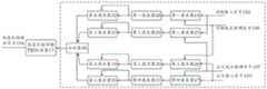
针对这种情况,本专利提出了一种新型具有标度因数自补偿功能的谐振式陀螺闭环控制系统,在正交闭环控制和力平衡检测的基础上,通过标度因数控制环路,补偿标度因数随环境的变化量,使系统的标度因数处于一定的稳定状态,构成具有标度因数自补偿功能的新型力平衡控制系统19整个系统的原理框图如图4所示,校正环路的具体结构框图如图5所示。陀螺工作时,陀螺振动位移对应的电容变化通过驱动C-V转换器2、检测C-V转换器8和驱动A-D转换器3、检测A-D转换器9分别输入驱动环路和检测环路。驱动环路中,通过驱动相位控制器5和驱动幅值控制器4使得陀螺的驱动轴保持恒幅振动状态。检测环路中,通过正交误差抑制环路(调轴控制环路)抑制正交误差信号,正交误差抑制环路包括正交解调器10、正交抑制PID控制器11和正交修调电压模块12。低噪声角速度检测通过同相力平衡控制环路(即力平衡环路)实现,同相力平衡控制环路包括同相解调控制器13、力反馈PID控制器14和检测解调控制器15及检测D-A转换器18。其中,力反馈回路PID控制器14的输出为陀螺的检测角速度输出即陀螺输出信号105。此外,在同相力平衡控制环路的力反馈PID控制器14后叠加一个外加校正调制信号101(即校正解调信号,设其简化形式可设为K1sinωrt),该校正调制信号101的频率需大于力平衡和正交误差抑制环路的环路带宽,使陀螺可以对该信号产生响应。陀螺产生响应后,在原有环路的基础上,将检测二次解调得到的同相解调输出的同相输入信号102和正交解调输出的正交输入信号103输入校准环路中。用同相校正解调信号106(即校正解调信号与输入调制信号同频同相,设其简化形式为K2sinωrt)和正交校正解调信号107(即校正解调信号,与输入调制信号同频但相位相差90度,设其简化形式为K3cosωrt)对同相输入信号102和正交输入信号103各进行两次乘法解调,对应的乘法器为第一乘法器24、第二乘法器25、第三乘法器26、第四乘法器27。用截止频率低于调制信号频率的低通第一滤波器28、第二滤波器29、第三滤波器30、第四滤波器31对四路解调输出进行滤波,再使用第五乘法器32、第六乘法器33、第七乘法器34、第八乘法器35四个乘法器提取滤波后信号的幅值。将四路幅值信号输入加法器36中,再将加法器36输出的幅值输入至标度补偿回路PID控制器17中,得到陀螺的标度补偿输出信号104。标度补偿输出信号104与调制前的力反馈信号相乘,直接调控标度因数,而标度因数的大小则主要由标度因数补偿回路PID控制器的设定值决定。整个系统的工作流程如图3所不。In view of this situation, this patent proposes a new type of resonant gyro closed-loop control system with scale factor self-compensation function. On the basis of quadrature closed-loop control and force balance detection, through the scale factor control loop, the The variation of the degree factor with the environment makes the scale factor of the system in a certain stable state, and constitutes a new type of force balance control system with the function of self-compensation of the scale factor. The principle block diagram of the entire system is shown in Figure 4. The specific structural block diagram is shown in Figure 5. When the gyro is working, the capacitance change corresponding to the vibration displacement of the gyro is input to the driving loop and the detection loop respectively through the driving
该标度因数控制系统的的理论分析如下。首先,根据文献[Lynch,D.,“VibratoryGyro Analysis by the Method of Averaging,”Proc.2nd St.Petersburg Conf.onGyroscopic Technology and Navigation,St.Petersburg,Russia,May24-25,1995,pp.26-34.]。陀螺检测轴的运动方程可以表示为:The theoretical analysis of the scale factor control system is as follows. First, according to the literature [Lynch, D., "VibratoryGyro Analysis by the Method of Averaging," Proc.2nd St.Petersburg Conf.onGyroscopic Technology and Navigation, St.Petersburg, Russia, May24-25, 1995, pp.26-34 .]. The motion equation of the gyro detection axis can be expressed as:

其中in
k12=ωΔω sin 2θω,
其中y为检测轴振动位移,

将驱动位移信号、反馈力信号和虚拟调制电压信号分别表示为:The driving displacement signal, feedback force signal and virtual modulation voltage signal are expressed as:
x=x0 sin ωdt,fy=Fy cos ωdt,Vvir=K sin ωrtx=x0 sin ωd t, fy =Fy cos ωd t, Vvir =K sin ωr t
其中,施加到检测电极上的静电力为fy,幅值为Fy,其由两部分组成,一部分fy1为力平衡反馈力,幅值为FB;另一部分fy2为由虚拟调制电压信号产生的检测轴静电力分量,幅值为K,频率为ωr,t表示时间,即:Among them, the electrostatic force applied to the detection electrode is fy , the amplitude is Fy , which consists of two parts, one part fy1 is the force balance feedback force, and the amplitude is FB ; the other part fy2 is the virtual modulation voltage The electrostatic force component of the detection shaft generated by the signal has an amplitude of K, a frequency of ωr , and t represents time, namely:


此时,检测轴运动方程可表示为:At this time, the motion equation of the detection axis can be expressed as:

即:which is:

该方程的稳态解为:The steady-state solution to this equation is:

其中为了显示结果方便,定义了M1、β1、M2、β2、M3、β3六个量,表示式如下:For the convenience of displaying the results, six quantities of M1 , β1 , M2 , β2 , M3 and β3 are defined, and the expressions are as follows:


该稳态解即为施加虚拟调制信号后,陀螺检测轴的振动响应。对该信号分别进行同相和正交解调,得到的信号输入如图5所示的校正环路再用虚拟调制信号进行同相和正交解调,最后再通过乘法器和加法器实现幅值提取,从而消除了二次解调相位误差和虚拟调制信号解调相位误差的影响。设最终加法器输出信号为Add,则其表达式为:The steady state solution is the vibration response of the gyro detection axis after the virtual modulation signal is applied. In-phase and quadrature demodulation are performed on the signal respectively, and the obtained signal is input to the correction loop shown in Figure 5, and then the in-phase and quadrature demodulation is performed with the virtual modulation signal, and finally the amplitude is extracted by the multiplier and the adder. , thereby eliminating the influence of the secondary demodulation phase error and the demodulation phase error of the virtual modulation signal. Assuming that the final adder output signal is Add , its expression is:

通过数值分析可知,β2≈-β3,故cos(β2+β3)≈1,故上式可化简为:Numerical analysis shows that β2 ≈-β3 , so cos(β2 +β3 )≈1, so the above formula can be simplified to:

通过PID控制器闭环控制加法器输出值,可以消除影响标度因数变化的主要因素。通过分析和仿真可知,添加该校正环路后,可以有效抑制由驱动谐振频率和陀螺电容间隙变化所引起的标度因数变化,但是无法抑制由频差和力反馈相位误差引起的标度因数变化。频差变化对标度因数具有一定的影响,但从仿真上可以看出,该影响很小,而且对于全对称式的模态匹配陀螺而言,驱动模态和检测模态的频率随温度的变化基本都呈线性,且系数基本一致,因此可以认为在温度变化过程中,频差的改变量很小。对于力反馈相位误差而言,确实无法通过该方法消除其对于标度因数的影响,但是根据以往的调试经验和测试数据分析,该相位差基本由电路系统决定,外界环境因素对该参数的影响很小,基本可以忽略。而驱动谐振频率和驱动检测电容间隙(认为驱动和检测电容间隙一致,且随温度的变化量相同)这两个参数,在外界环境(主要是温度)变化过程中,变化幅度最大,对标度因数影响也最大,该方法可以抑制这两个参数引起的标度因数该变量,就抑制了由外界环境导致标度因数变化的主要因素。By controlling the output value of the adder in a closed loop with a PID controller, the main factor affecting the change of the scale factor can be eliminated. Through analysis and simulation, it can be seen that after adding the correction loop, the scale factor change caused by the drive resonant frequency and the gyro capacitance gap change can be effectively suppressed, but the scale factor change caused by the frequency difference and the force feedback phase error cannot be suppressed. . The change of frequency difference has a certain influence on the scale factor, but it can be seen from the simulation that the influence is very small, and for a fully symmetrical modal matching gyroscope, the frequency of the driving mode and the detection mode varies with temperature. The changes are basically linear, and the coefficients are basically the same, so it can be considered that in the process of temperature change, the change of the frequency difference is small. For the force feedback phase error, it is indeed impossible to eliminate its influence on the scale factor by this method, but according to the previous debugging experience and test data analysis, the phase difference is basically determined by the circuit system, and the influence of external environmental factors on this parameter It is very small and can basically be ignored. The two parameters, the driving resonant frequency and the driving detection capacitance gap (it is considered that the driving and detection capacitance gaps are the same and have the same amount of change with temperature), have the largest change range during the change of the external environment (mainly temperature). The influence of the factor is also the largest. This method can suppress the variable of the scale factor caused by these two parameters, thus suppressing the main factor of the change of the scale factor caused by the external environment.
上述校正解调信号本质上是对陀螺正常工作状态的一种扰动,通过陀螺对该扰动的响应,判断陀螺此时的状态,从而进行状态的检测和控制。校正调制信号的幅值不能过小,如果幅值过小,陀螺对该扰动没有响应,也就无法实现状态监控;但是幅值也不能过大,如果幅值很大,会对陀螺正常的工作状态造成过大的干扰,导致陀螺工作不正常,本方案的目标是在陀螺正常工作时实现校正。因此,校正信号的幅值是需要根据陀螺结构的特点、电路的特点来综合选择的。The above correction and demodulation signal is essentially a disturbance to the normal working state of the gyro, and the state of the gyro at this time is judged by the gyro's response to the disturbance, so as to detect and control the state. The amplitude of the correction modulation signal cannot be too small. If the amplitude is too small, the gyroscope will not respond to the disturbance, and state monitoring cannot be achieved; however, the amplitude cannot be too large. If the amplitude is too large, the gyro will work normally. The state causes excessive interference and causes the gyro to work abnormally. The goal of this scheme is to achieve correction when the gyro is working normally. Therefore, the amplitude of the correction signal needs to be comprehensively selected according to the characteristics of the gyro structure and the characteristics of the circuit.
下面利用Matlab Simulink软件对上述控制系统和方法进行仿真验证。整体思路为:首先建立陀螺谐振模型和电路系统模型,通过基础仿真验证了模型的准确性。接下来,分别仿真添加校正环路和未添加校正环路情况下,陀螺系统的标度因数在各种参数变化的情况下发生怎样的变化。如果改变一个参数,标度因数在未加校正环路时发生相应的变化,而添加校正环路后,基本保持不变,则可以说明该校正系统使得系统的标度因数不受该因素的影响。仿真结果指出,该系统可以有效抑制驱动谐振频率和电容间隙的改变对于标度因数的影响,而这两个因素也是影响标度因数变化的主要因素。The above-mentioned control system and method are simulated and verified by using Matlab Simulink software. The overall idea is as follows: Firstly, the gyro resonance model and circuit system model are established, and the accuracy of the model is verified through basic simulation. Next, simulate how the scale factor of the gyro system changes when various parameters are changed when the correction loop is added and the correction loop is not added. If a parameter is changed, the scale factor changes correspondingly when no correction loop is added, but remains basically unchanged after adding the correction loop, it can be shown that the correction system makes the scale factor of the system not affected by this factor . The simulation results show that the system can effectively suppress the influence of the drive resonant frequency and the capacitance gap change on the scale factor, and these two factors are also the main factors affecting the change of the scale factor.
下面为有效性仿真验证的具体过程:The following is the specific process of validity simulation verification:
(一)基本模型验证(1) Basic model verification
为了便于通过改变参数来研究参数变化对于标度因数的影响以及标度因数控制环路的功能,将谐振结构的基本参数和电路系统的相关参数设置为模型的输入参数,包括驱动轴Q值Q1、驱动轴谐振频率ωd、检测轴Q值Q2、检测轴频率ωs、刚度轴初始偏角θω、阻尼轴初始偏角θτ、驱动电容间隙d0d、检测电容间隙d0s、驱动电压-力的转换系数Dv-f、检测电压-力的转换系数Sv-f、驱动差分电容-电压的转换系数Dc-v、检测差分电容-电压的转换系统Sc-v、反馈力相位误差

根据理论建立了系统模型后,需要首先验证模型的正确性,即各个环路是否正常工作且实现了其理论功能。驱动闭环的功能是实现驱动方向的恒幅振动,其功能的判断标准为系统开启后,陀螺驱动轴位移输出信号是否在一段时间后保持稳定。图6为仿真结果,其中上下子图分别表示驱动轴位移信号输出和检测轴位移信号输出,横轴代表时间,单位为秒,纵轴代表幅值。在进行该仿真时,为了避免干扰,刚度轴偏角(导致正交误差的主要因素)误差参数设为0,且正交回路断开。从图6中可以看出,系统开启后,经过大约2s,驱动位移达到稳定状态并一直保持。说明驱动闭环控制正常。After the system model is established according to the theory, it is necessary to verify the correctness of the model first, that is, whether each loop works normally and realizes its theoretical function. The function of the drive closed-loop is to realize constant amplitude vibration in the drive direction. The criterion for its function is whether the output signal of the gyro drive shaft displacement remains stable after a period of time after the system is turned on. Figure 6 shows the simulation results, in which the upper and lower subgraphs respectively represent the output of the drive shaft displacement signal and the output of the detection shaft displacement signal, the horizontal axis represents time, in seconds, and the vertical axis represents amplitude. During this simulation, in order to avoid interference, the error parameter of the stiffness axis declination (the main factor causing the quadrature error) is set to 0, and the quadrature loop is disconnected. It can be seen from Fig. 6 that after the system is turned on, the driving displacement reaches a steady state and remains constant after about 2 s. Indicates that the drive closed-loop control is normal.
接下来对正交误差抑制回路进行验证。进行该仿真时,设置刚度轴偏角不为0,引起正交误差。正交误差表现为由驱动位移导致的检测位移输出。而正交误差抑制回路则会在该误差出现时,通过静电调刚度,将该误差抑制到0。图7为仿真结果,其中上下子图分别表示驱动轴位移信号输出和检测轴位移信号输出,横轴代表时间,单位为秒,纵轴代表幅值。从检测位移曲线可以看出,正交误差在刚开始出现后,逐渐被抑制到0,说明正交误差抑制回路功能正常。Next, the quadrature error suppression loop is verified. When performing this simulation, set the stiffness axis declination angle to be different from 0, resulting in an orthogonal error. Quadrature errors appear as detected displacement outputs due to drive displacements. The quadrature error suppression loop will suppress the error to 0 by electrostatically adjusting the stiffness when the error occurs. Figure 7 shows the simulation results, in which the upper and lower subgraphs represent the output of the drive shaft displacement signal and the output of the detection shaft displacement signal, respectively, the horizontal axis represents time in seconds, and the vertical axis represents amplitude. It can be seen from the detection displacement curve that the quadrature error is gradually suppressed to 0 after the initial appearance, indicating that the quadrature error suppression loop functions normally.
接下来对力平衡环路进行验证。力平衡环路是否正常工作主要表现在向系统输入角速度后,系统能否通过反馈力抵消哥氏力,将检测方向位移抑制为0,且反馈力大小与输入角速度大小呈正比。在验证时,首先在无角速度输入情况下启动系统,等待稳定后,分别输入不同大小的角速度(该实施例为:0.1-0.2-0.4-0.8)。仿真出的驱动和检测轴位移输出曲线如图8所示,其中上下子图分别表示驱动轴位移信号输出和检测轴位移信号输出,横轴代表时间,单位为秒,纵轴代表幅值。从检测位移曲线可以看出,输入角速度后,检测轴位移出现抖动,但不久遍被抑制到0。说明力反馈系统起了作用。Next, the force balance loop is verified. Whether the force balance loop works normally mainly depends on whether the system can offset the Coriolis force through the feedback force after inputting the angular velocity to the system, and suppress the displacement in the detection direction to 0, and the magnitude of the feedback force is proportional to the magnitude of the input angular velocity. During verification, first start the system without angular velocity input, and after waiting for stabilization, input angular velocities of different magnitudes (in this example: 0.1-0.2-0.4-0.8). The simulated driving and detection shaft displacement output curves are shown in Figure 8, in which the upper and lower subgraphs represent the driving shaft displacement signal output and the detection shaft displacement signal output respectively, the horizontal axis represents the time in seconds, and the vertical axis represents the amplitude. It can be seen from the detection displacement curve that after inputting the angular velocity, the detection axis displacement appears jitter, but it is suppressed to 0 soon. It shows that the force feedback system works.
进一步地,记录不同角速度下陀螺稳定状态的输出曲线,如图9所示,其中上子图为被调制后的反馈力信号,下子图为反馈力信号幅值。测得输入角速度序列对应的反馈力幅值分别为:-2.264,-4.526,-9.050,-18.10,陀螺输出与角速度输入呈正比,说明整个陀螺模型和控制系统是基本准确的。Further, the output curves of the gyro steady state under different angular velocities are recorded, as shown in FIG. 9 , where the upper subgraph is the modulated feedback force signal, and the lower subgraph is the feedback force signal amplitude. The measured feedback force amplitudes corresponding to the input angular velocity sequence are: -2.264, -4.526, -9.050, -18.10. The gyro output is proportional to the angular velocity input, indicating that the entire gyro model and control system are basically accurate.
(二)未补偿情况下标度因数影响因素分析(2) Analysis of the influencing factors of the scaling factor without compensation
如果添加校正环路后,标度因数的主要影响因素对于标度因数的影响大幅降低或完全消失了,说明标度因数控制环路起了作用。因此,在验证标度因数校正环路有效性之前,需要知道影响标度因数的主要因素。If after adding the correction loop, the influence of the main influence factor of the scale factor on the scale factor is greatly reduced or disappears completely, it means that the scale factor control loop is working. Therefore, before verifying the validity of the scale factor correction loop, the main factors affecting the scale factor need to be known.
仿真验证时,首先设定一组参数作为基准,仿真得到此时的标度因数。之后,采用控制变量的原则,改变谐振结构和电路系统的各项参数并测得对应的标度因数。最后,综合参数变量和标度因数值的变化情况,与理论进行对比。对于每一组参数,测量其对应的标度因数时,首先设置输入角速度为0,开启仿真,待系统各环路控制稳定后,记录此时同相回路PID输出值,即陀螺系统在该参数下的零偏输出值;记录后将角速度改为1,等待系统环路控制稳定后,记录下此时同相回路PID输出值,即陀螺系统对于正单位角速度的输出;用后者的数值减去零偏值即得到该组参数对应的标度因数大小。During the simulation verification, a set of parameters is firstly set as the benchmark, and the simulation obtains the scale factor at this time. After that, using the principle of control variables, the parameters of the resonant structure and circuit system are changed and the corresponding scale factors are measured. Finally, the changes of parameter variables and scale factor values are synthesized and compared with the theory. For each group of parameters, when measuring the corresponding scale factor, first set the input angular velocity to 0, start the simulation, and after the control of each loop of the system is stable, record the PID output value of the in-phase loop at this time, that is, the gyro system is under this parameter After recording, change the angular velocity to 1, wait for the system loop control to stabilize, and record the PID output value of the in-phase loop at this time, that is, the output of the gyro system for a positive unit angular velocity; subtract zero from the latter value The bias value is the size of the scale factor corresponding to this group of parameters.
变参数后的仿真结果如表1所示。从表中仿真结果可以分析得到,驱动检测轴的Q值对力平衡模式参数无影响、驱动V-f系数对标度无影响而检测V-f系数和标度成反比(该系数主要由检测电容间隙决定)、驱动位移-电容系数与标度呈反比(系数越大驱动位移越小,因为驱动差分电容大小是恒幅控制的,该系数主要由驱动电容间隙决定),检测位移-电容系数的系数对标度无影响、频差对标度有微小影响、驱动频率与标度呈正比、间隙变化和标度是4次方的关系、二次解调相位误差对标度无影响、反馈力相位误差对标度有影响,标度变为原标度乘以误差角度的cos值、初始阻尼轴偏角对标度无影响、初始刚度轴偏角对标度无影响。整体仿真结果与理论分析结果基本相符。The simulation results after changing the parameters are shown in Table 1. From the simulation results in the table, it can be obtained that the Q value of the driving detection shaft has no effect on the parameters of the force balance mode, the driving V-f coefficient has no effect on the scale, and the detection V-f coefficient is inversely proportional to the scale (the coefficient is mainly determined by the detection capacitance gap) 、The driving displacement-capacitance coefficient is inversely proportional to the scale (the larger the coefficient, the smaller the driving displacement, because the driving differential capacitance is controlled by constant amplitude, and the coefficient is mainly determined by the driving capacitance gap), and the coefficient of detecting the displacement-capacitance coefficient is based on the standard The frequency difference has no effect on the scale, the driving frequency is proportional to the scale, the gap change and the scale are in a quadratic relationship, the secondary demodulation phase error has no effect on the scale, and the feedback force phase error has no effect on the scale. The scale has an effect, the scale becomes the cos value of the original scale multiplied by the error angle, the initial damping axis declination has no effect on the scale, and the initial stiffness axis declination has no effect on the scale. The overall simulation results are basically consistent with the theoretical analysis results.
温度等外界环境因素的变化会导致陀螺驱动轴谐振频率、电容间隙等参数发生变化,导致标度因数产生变化。用传统的直接拟合法和多参数综合拟合法来补偿标度因数需要依赖大量的测试数据,耗时耗力,而且如果陀螺状态发生变化会导致补偿结果不准确。因此,急需一种标度因数的控制方法实现其自标定。Changes in external environmental factors such as temperature will lead to changes in parameters such as the resonant frequency of the gyro drive shaft and the capacitance gap, resulting in changes in the scale factor. Compensating the scale factor with the traditional direct fitting method and multi-parameter comprehensive fitting method needs to rely on a large amount of test data, which is time-consuming and labor-intensive, and if the state of the gyro changes, the compensation result will be inaccurate. Therefore, a scale factor control method is urgently needed to realize its self-calibration.
表1:标度因数校正环路未启动的情况下,仿真验证标度因数与陀螺系统参数之间的关系Table 1: Simulation verifies the relationship between scale factor and gyro system parameters without the scale factor correction loop enabled

(三)标度因数校正环路有效性验证(3) Validity verification of the scale factor correction loop
接下来对标度因数校正环路的有效性进行验证。与仿真验证标度因数计算理论的思路相同,在进行标度因数控制方法有效性验证时,首先确定一组参数作为基准,仿真得到此时的标度因数,之后,依据控制变量的原则,改变谐振结构和电路系统参数,记录标度因数的变化情况。根据仿真结果,综合上一部分的仿真数据,对比在标准的力平衡模式下和标度因数校准控制模式下,各参数的变化对于标度因数的影响是否有区别。添加校正回路后,参数变化对于标度因数影响的仿真结果如表2所示。Next, the validity of the scale factor correction loop is verified. The same idea as the simulation verification scale factor calculation theory, when verifying the validity of the scale factor control method, first determine a set of parameters as the benchmark, and obtain the scale factor at this time through simulation, and then change the scale factor according to the principle of the control variable. Resonant structure and circuit system parameters, record the change of scale factor. According to the simulation results, synthesizing the simulation data in the previous part, it is compared whether the influence of each parameter change on the scale factor is different between the standard force balance mode and the scale factor calibration control mode. After adding the correction loop, the simulation results of the effect of parameter changes on the scaling factor are shown in Table 2.
从表中可以看出,添加校正环路后,可以有效抑制由驱动谐振频率和陀螺电容间隙变化所引起的标度因数变化,但是无法抑制由频差和力反馈相位误差引起的标度因数变化。频差变化对标度因数具有一定的影响,但从仿真上可以看出,该影响很小,而且对于全对称式的模态匹配陀螺而言,驱动模态和检测模态的频率随温度的变化基本都呈线性,且系数基本一致,因此可以认为在温度变化过程中,频差的改变量很小。对于力反馈相位误差而言,确实无法通过该方法消除其对于标度因数的影响,但是根据以往的调试经验和测试数据分析,该相位差基本由电路系统决定,外界环境因素对该参数的影响很小,基本可以忽略。而驱动谐振频率和驱动检测电容间隙(认为驱动和检测电容间隙一致,且随温度的变化量相同)这两个参数,在外界环境(主要是温度)变化过程中,变化幅度最大,对标度因数影响也最大,该方法可以抑制这两个参数引起的标度因数该变量,就抑制了由外界环境导致标度因数变化的主要因素。该仿真结果证明了该标度因数控制方法的有效性。It can be seen from the table that after adding the correction loop, the scale factor change caused by the drive resonant frequency and the gyro capacitance gap change can be effectively suppressed, but the scale factor change caused by the frequency difference and the force feedback phase error cannot be suppressed. . The change of frequency difference has a certain influence on the scale factor, but it can be seen from the simulation that the influence is very small, and for a fully symmetrical modal matching gyroscope, the frequency of the driving mode and the detection mode varies with temperature. The changes are basically linear, and the coefficients are basically the same, so it can be considered that in the process of temperature change, the change of the frequency difference is small. For the force feedback phase error, it is indeed impossible to eliminate its influence on the scale factor by this method, but according to the previous debugging experience and test data analysis, the phase difference is basically determined by the circuit system, and the influence of external environmental factors on this parameter It is very small and can basically be ignored. The two parameters, the driving resonant frequency and the driving detection capacitance gap (it is considered that the driving and detection capacitance gaps are the same and have the same amount of change with temperature), have the largest change range during the change of the external environment (mainly temperature). The influence of the factor is also the largest. This method can suppress the variable of the scale factor caused by these two parameters, thus suppressing the main factor of the change of the scale factor caused by the external environment. The simulation results demonstrate the effectiveness of the scaling factor control method.
表2:标度因数校正环路启动时,仿真验证标度因数随主要参数的变化情况Table 2: Simulation Verification Scale Factor Variation with Key Parameters When Scale Factor Correction Loop Starts

实施例二
参见图4、图5,与上述实施例一对应地,本发明还提供一种谐振式陀螺闭环控制系统,包括:驱动环路、检测环路、标度补偿环路;其中驱动环路用于在驱动模态下,对输入的第一信号进行转换和调制、闭环控制、调制,最终生成驱动控制信号输入驱动电极,以激励谐振子在驱动方向恒幅振动;所述第一信号用于表征陀螺仪驱动方向即驱动电极的振动位移;检测环路用于检测陀螺仪输入的轴向角速度;检测环路包括:正交误差抑制环路和力平衡环路,正交误差抑制环路用于在检测模态下,对输入的第二信号进行解调、处理生成正交控制信号输入正交误差修调电极,以抑制正交误差信号;力平衡环路用于在检测模态下,对输入的第二信号进行解调、处理生成角速度的检测信号,该信号输入检测电极后会产生静电力,用于抵消由输入角速度产生的哥氏力,以使得谐振子在检测方向上维持静止的平衡状态在受力平衡状态下实现轴向角速度检测;所述第二信号用于表征陀螺仪检测方向即检测电极的振动位移;标度补偿环路用于对经正交误差抑制环路解调后的信号及经力平衡环路解调后的信号分别进行信号解调和幅值运算;对所述幅值进行以设定值为目标的PID控制运算,获得标度补偿信号;所述力平衡环路还用于将角速度检测信号与所述校正解调信号叠加后与提取的幅值进行幅值运算输入检测电极,以实现对陀螺仪的标度因数自动补偿。Referring to FIG. 4 and FIG. 5 , corresponding to the first embodiment above, the present invention also provides a resonant gyro closed-loop control system, including: a drive loop, a detection loop, and a scale compensation loop; wherein the drive loop is used for In the drive mode, the input first signal is converted and modulated, closed-loop controlled, and modulated, and finally a drive control signal is generated and input to the drive electrode to excite the resonator to vibrate at a constant amplitude in the drive direction; the first signal is used to characterize The driving direction of the gyroscope is the vibration displacement of the driving electrode; the detection loop is used to detect the axial angular velocity input by the gyroscope; the detection loop includes: the quadrature error suppression loop and the force balance loop, the quadrature error suppression loop is used for In the detection mode, the input second signal is demodulated and processed to generate a quadrature control signal, which is input to the quadrature error trimming electrode to suppress the quadrature error signal; the force balance loop is used in the detection mode to The input second signal is demodulated and processed to generate a detection signal of angular velocity. After the signal is input to the detection electrode, an electrostatic force will be generated to offset the Coriolis force generated by the input angular velocity, so that the resonator remains stationary in the detection direction. The balance state realizes the axial angular velocity detection under the force balance state; the second signal is used to characterize the detection direction of the gyroscope, that is, the vibration displacement of the detection electrode; the scale compensation loop is used to demodulate the quadrature error suppression loop Signal demodulation and amplitude calculation are respectively performed on the obtained signal and the signal demodulated by the force balance loop; PID control calculation is carried out on the amplitude value with a set value as the target to obtain a scale compensation signal; The balanced loop is also used to superimpose the angular velocity detection signal and the correction and demodulation signal, perform amplitude operation on the extracted amplitude, and input it to the detection electrode, so as to realize automatic compensation of the scale factor of the gyroscope.
参见图4,所述力平衡环包括依次串联的检测C-V转换器、检测A-D转换器、同相解调器、力反馈PID控制器、检测调制器和检测D-A转换器;Referring to FIG. 4 , the force balance loop includes a detection C-V converter, a detection A-D converter, an in-phase demodulator, a force feedback PID controller, a detection modulator and a detection D-A converter connected in series in sequence;
所述正交误差抑制环路包括依次串联的检测C-V转换器、检测A-D转换器、正交解调器、正交抑制PID控制器、正交修调电压模块;The quadrature error suppression loop includes a detection C-V converter, a detection A-D converter, a quadrature demodulator, a quadrature suppression PID controller, and a quadrature trim voltage module connected in series in sequence;
所述驱动环路包括依次串联的驱动C-V转换器、驱动A-D转换器、驱动控制器、驱动调制器和驱动D-A转换器;所述驱动控制器由驱动相位控制器和驱动幅值控制器并联形成。上述元件均可采用现有的元件,均能从市场直接采购获得。The drive loop includes a drive C-V converter, a drive A-D converter, a drive controller, a drive modulator and a drive D-A converter in series; the drive controller is formed by a drive phase controller and a drive amplitude controller in parallel . The above-mentioned components can all use existing components and can be directly purchased from the market.
优选地,标度补偿环路,包括:信号发生源、信号解调与幅值提取模块16、标度补偿回路控制器(本实施例中采用标度补偿回路PID控制器17);信号发生源,用于产生校正解调信号,所述校正解调信号的频率大于正交误差抑制环路和力平衡环路输入信号的带宽;以使陀螺仪的检测轴相应振动;信号解调与幅值提取模块16对输入的经正交误差抑制环路解调后的信号和经力平衡环路解调后的信号分别通过校正解调信号解调和幅值运算后提取幅值;标度补偿回路控制器对所述幅值进行PID控制运算获得标度补偿信号并输出;所述力平衡环路用于将轴向角速度检测信号与所述调制解调信号叠加后与提取的幅值进行乘法运算输入检测电极,以实现对陀螺仪的标度因数自动补偿。Preferably, the scale compensation loop includes: a signal generation source, a signal demodulation and amplitude extraction module 16, a scale compensation loop controller (in this embodiment, a scale compensation loop PID controller 17 is used); the signal generation source , used to generate a correction demodulation signal whose frequency is greater than the bandwidth of the input signal of the quadrature error suppression loop and the force balance loop; so that the detection axis of the gyroscope vibrates accordingly; the signal demodulation and amplitude The extracting module 16 extracts the amplitude after demodulating the input signal by the quadrature error suppression loop and the signal demodulating by the force balance loop respectively through the correction demodulation signal demodulation and amplitude calculation; the scale compensation loop The controller performs a PID control operation on the amplitude to obtain a scale compensation signal and outputs it; the force balance loop is used to multiply the extracted amplitude after the axial angular velocity detection signal and the modulation and demodulation signal are superimposed. Input detection electrodes for automatic compensation of the scale factor of the gyroscope.
优选地,参见图5,所述信号发生源,用于发生同频率的同相解调信号、正交解调信号及校正调制信号;所述信号解调与幅值提取模块包括:四路并联的幅值运算单元;每一路幅值运算单元分别包括依次串联的一级乘法器、滤波器、二级乘法器;分别用于对同相解调信号对正交输入信号进行同相同频解调生成的第一幅值、同相解调信号对同相输入信号进行同相同频解调生成的第二幅值、正交解调信号对正交输入信号进行90度相位差同频解调生成的第三幅值、正交解调信号对同相输入信号进行90度相位差同频解调生成的第四幅值依次进行运算并生成第五幅值、第六幅值、第七幅值、第八幅值;加法器,用于对生成的第五幅值、第六幅值、第七幅值、第八幅值做加法运算获得最终幅值以供提取。Preferably, referring to FIG. 5 , the signal generation source is used to generate in-phase demodulation signals, quadrature demodulation signals and correction modulation signals of the same frequency; the signal demodulation and amplitude extraction module includes: four parallel channels Amplitude operation unit; each way of amplitude operation unit respectively comprises a first-level multiplier, a filter, and a second-level multiplier connected in series in sequence; The first amplitude value, the second amplitude value generated by the same-frequency demodulation of the in-phase demodulation signal on the in-phase input signal, the third amplitude value generated by the quadrature demodulation signal subjected to the same-frequency demodulation of the quadrature input signal with a phase difference of 90 degrees value and quadrature demodulation signal The fourth amplitude value generated by the 90-degree phase difference co-frequency demodulation of the in-phase input signal is sequentially calculated to generate the fifth amplitude value, the sixth amplitude value, the seventh amplitude value, and the eighth amplitude value. ; The adder is used to add the generated fifth amplitude value, sixth amplitude value, seventh amplitude value and eighth amplitude value to obtain the final amplitude value for extraction.
所述陀螺的谐振子结构采用单晶硅等高热导率材料制造,陀螺包含了对称分布的多组电极。本发明所述的谐振式陀螺闭环控制系统在正交闭环控制和力平衡检测的基础上,通过标度因数控制环路来调整陀螺的输出,补偿标度因数随环境的变化量,使系统的标度因数处于一定的稳定状态,从而在实现陀螺低噪声角速度检测的同时,保证标度因数的稳定性。The resonator structure of the top is made of high thermal conductivity materials such as single crystal silicon, and the top includes multiple groups of electrodes that are symmetrically distributed. On the basis of orthogonal closed-loop control and force balance detection, the resonant gyro closed-loop control system of the present invention adjusts the output of the gyro through the scale factor control loop, compensates the change of the scale factor with the environment, and makes the system The scale factor is in a certain stable state, so that the stability of the scale factor is ensured while the low-noise angular velocity detection of the gyro is realized.
整个系统由驱动环路、正交误差抑制环路、力平衡环路和标度补偿环路构成,可以在实现高精度的角速度信号检测的同时,保持系统标度因数的稳定性。工作过程中,陀螺振动位移对应的电容变化通过C-V转换器和A-D转换器分别输入驱动环路和检测环路。驱动环路中,通过驱动相位控制器和幅值控制器使得陀螺的驱动轴保持恒幅振动状态。检测环路中,信号又分别经过同相解调和正交解调进入力平衡环路和正交误差抑制环路。在正交误差抑制环路中,输入信号先经过正交解调器的解调,滤波后被输入正交抑制PID控制器中,PID控制器的输出控制正交修调电压模块,实现正交误差信号的闭环抑制。在力平衡环路中,输入信号先经过同相解调器的解调,滤波后被输入力反馈PID控制器中,PID控制器的输出通过调制得到用于抵消哥氏力的静电力信号,该PID的输出与外界输入角速度呈一定的比例关系,因此该输出既陀螺的角速度测量输出。标度因数控制环路由调制信号模块和标度因数补偿环路构成,其中所述的调制信号叠加在力反馈PID控制器输出后,所述的标度因数补偿环路为双输入单输出的功能环路,输入为力反馈回路和正交控制回路的解调量,输出为调控陀螺输出大小的控制信号。当两路解调信号进入标度因数补偿环路后,各自进行以调制信号为基准的同相和正交乘法解调,使用截止频率低于调制信号的低通滤波器对思路解调输出信号进行滤波,使用乘法器提取解调后的幅值,将四个幅值之和输入PID控制器中,得到调控陀螺输出大小的控制信号。上述标度因数控制环路的设计,可以有效降低陀螺振动信号二次解调环节的相位误差和校正环路输入信号解调的相位误差,从而实现高精度的标度因数闭环控制。The whole system consists of a drive loop, a quadrature error suppression loop, a force balance loop and a scale compensation loop, which can achieve high-precision angular velocity signal detection while maintaining the stability of the scale factor of the system. During the working process, the capacitance change corresponding to the vibration displacement of the gyro is input to the driving loop and the detection loop respectively through the C-V converter and the A-D converter. In the drive loop, the drive shaft of the gyro keeps a constant amplitude vibration state by driving the phase controller and the amplitude controller. In the detection loop, the signal enters the force balance loop and the quadrature error suppression loop through in-phase demodulation and quadrature demodulation respectively. In the quadrature error suppression loop, the input signal is first demodulated by the quadrature demodulator, and after filtering, it is input into the quadrature suppression PID controller. The output of the PID controller controls the quadrature trim voltage module to realize quadrature Closed-loop rejection of error signals. In the force balance loop, the input signal is first demodulated by the in-phase demodulator, and then input to the force feedback PID controller after filtering. The output of the PID controller is modulated to obtain the electrostatic force signal used to cancel the Coriolis force. The output of the PID is proportional to the external input angular velocity, so the output is the angular velocity measurement output of the gyro. The scale factor control loop is composed of a modulation signal module and a scale factor compensation loop. After the modulation signal is superimposed on the output of the force feedback PID controller, the scale factor compensation loop is a function of dual input and single output. Loop, the input is the demodulation quantity of the force feedback loop and the quadrature control loop, and the output is the control signal that regulates the output size of the gyro. After the two demodulation signals enter the scale factor compensation loop, they perform in-phase and quadrature multiplication demodulation respectively based on the modulated signal, and use a low-pass filter with a cutoff frequency lower than the modulated signal to perform the demodulation output signal of the idea. Filter, use the multiplier to extract the demodulated amplitude, and input the sum of the four amplitudes into the PID controller to obtain a control signal for regulating the output size of the gyro. The above design of the scale factor control loop can effectively reduce the phase error of the secondary demodulation link of the gyro vibration signal and the phase error of the correction loop input signal demodulation, thereby realizing high-precision scale factor closed-loop control.
所述的标度补偿环路中调制信号的频率要在一定的范围内,如果信号频率过高,则陀螺对其响应过小,导致控制环路输入信号过小,信噪比很低,容易受到外界的干扰,而如果信号频率过低,则该信号输出可能影响陀螺正常的工作状态,对陀螺输出产生影响。因此,该外加调制信号的频率需要在一个合适的范围内,使得该信号输入既不影响陀螺的正常工作状态,又能使陀螺对其产生足够强度的响应。The frequency of the modulation signal in the scale compensation loop should be within a certain range. If the signal frequency is too high, the response of the gyro to it is too small, resulting in the control loop input signal being too small, and the signal-to-noise ratio is very low. Subject to external interference, and if the signal frequency is too low, the signal output may affect the normal working state of the gyro and affect the gyro output. Therefore, the frequency of the external modulation signal needs to be in an appropriate range, so that the input of the signal will not affect the normal working state of the gyro, but also enable the gyro to respond to it with sufficient strength.
所述的调制信号既可以是正弦信号也可以是方波信号等周期性信号。所述的标度补偿环路为多输入单输出的系统,其输入为正交环路和力反馈环路的解调量,输出为环路末端PID控制器的输出,对陀螺输出进行调控,实现标度因数的控制。The modulation signal can be either a sinusoidal signal or a periodic signal such as a square wave signal. The scale compensation loop is a multi-input single-output system, the input is the demodulation quantity of the quadrature loop and the force feedback loop, the output is the output of the PID controller at the end of the loop, and the gyro output is regulated, Implements the control of the scale factor.
所述标度补偿环路的信号解调与幅值提取模块中,使用与调制信号频率相同,相位分别是0度和90度(同相和正交)的两种信号作为解调信号,对输入的两路信号都进行两种方式的解调,并通过信号自身的乘法运算计算每一路解调信号的幅值。该方案适用于任何基于哥氏力效应的谐振陀螺。也包括使用力反馈原理来抑制正交信号的控制模式。In the signal demodulation and amplitude extraction module of the scale compensation loop, two signals with the same frequency as the modulated signal and the phases of 0 degrees and 90 degrees (in-phase and quadrature) are used as demodulation signals, and the input signal is The two channels of signals are demodulated in two ways, and the amplitude of each channel of demodulation signal is calculated by the multiplication of the signal itself. This scheme is applicable to any resonant gyroscope based on the Coriolis force effect. Also included are control modes that use force feedback principles to suppress quadrature signals.
以上所述仅为本发明的优选实施例,并非因此限制本发明的专利范围,凡是在本发明的发明构思下,利用本发明说明书及附图内容所作的等效结构变换,或直接/间接运用在其他相关的技术领域均包括在本发明的专利保护范围内。The above descriptions are only the preferred embodiments of the present invention, and are not intended to limit the scope of the present invention. Under the inventive concept of the present invention, the equivalent structural transformations made by the contents of the description and drawings of the present invention, or the direct/indirect application Other related technical fields are included in the scope of patent protection of the present invention.
Claims (9)
Translated fromChinesePriority Applications (1)
| Application Number | Priority Date | Filing Date | Title |
|---|---|---|---|
| CN202010416651.4ACN111578923B (en) | 2020-05-15 | 2020-05-15 | A resonant gyro closed-loop control method and system |
Applications Claiming Priority (1)
| Application Number | Priority Date | Filing Date | Title |
|---|---|---|---|
| CN202010416651.4ACN111578923B (en) | 2020-05-15 | 2020-05-15 | A resonant gyro closed-loop control method and system |
Publications (2)
| Publication Number | Publication Date |
|---|---|
| CN111578923Atrue CN111578923A (en) | 2020-08-25 |
| CN111578923B CN111578923B (en) | 2021-10-12 |
Family
ID=72125155
Family Applications (1)
| Application Number | Title | Priority Date | Filing Date |
|---|---|---|---|
| CN202010416651.4AActiveCN111578923B (en) | 2020-05-15 | 2020-05-15 | A resonant gyro closed-loop control method and system |
Country Status (1)
| Country | Link |
|---|---|
| CN (1) | CN111578923B (en) |
Cited By (31)
| Publication number | Priority date | Publication date | Assignee | Title |
|---|---|---|---|---|
| CN112611889A (en)* | 2020-12-08 | 2021-04-06 | 中国人民解放军陆军步兵学院石家庄校区 | Self-calibration method of micro-mechanical accelerometer based on electrostatic equivalent effect |
| CN112629557A (en)* | 2020-11-13 | 2021-04-09 | 上海航天控制技术研究所 | Automatic test equipment of MEMS gyroscope |
| CN113074756A (en)* | 2021-03-31 | 2021-07-06 | 中国人民解放军国防科技大学 | Error compensation method and device of rate integral type vibration gyro |
| CN113514079A (en)* | 2021-03-25 | 2021-10-19 | 中国海洋大学 | Frequency modulation gyro Lissajous modulation and self-correction test system |
| CN113514080A (en)* | 2021-05-19 | 2021-10-19 | 中国海洋大学 | Full-angle gyro online correction device and automatic trimming method based on virtual electric rotation |
| CN113532409A (en)* | 2021-06-18 | 2021-10-22 | 北京时代民芯科技有限公司 | High-precision digital MEMS gyroscope control system and method |
| CN113566844A (en)* | 2021-06-04 | 2021-10-29 | 上海航天控制技术研究所 | Harmonic oscillator kinetic parameter detection device based on interdigital electrode |
| CN113607150A (en)* | 2021-06-02 | 2021-11-05 | 北京理工大学 | Quartz gyro error suppression method of time division driving and orthogonal force feedback closed loop |
| CN113686356A (en)* | 2021-08-03 | 2021-11-23 | 中国船舶重工集团公司第七0七研究所 | Resonance gyro zero-bias online self-compensation system and method based on RBF network |
| CN113739821A (en)* | 2021-08-31 | 2021-12-03 | 北京航空航天大学 | Full-automatic magnetic compensation method of atomic spin gyroscope based on PID algorithm |
| CN113959424A (en)* | 2021-10-22 | 2022-01-21 | 苏州市职业大学 | A method, device and related components for orthogonal real-time correction of micromechanical gyroscope |
| CN113959427A (en)* | 2021-10-22 | 2022-01-21 | 北京航空航天大学 | Novel modulation-based real-time tracking method for closed-loop feedback coefficient of integrated optical gyroscope |
| CN114370887A (en)* | 2021-11-23 | 2022-04-19 | 上海航天控制技术研究所 | Zero-position self-calibration method of force balance mode vibration gyro based on virtual rotation |
| CN114370886A (en)* | 2021-11-23 | 2022-04-19 | 上海航天控制技术研究所 | Full-angle mode vibration gyro measurement error self-calibration method based on virtual rotation |
| CN114427854A (en)* | 2022-01-10 | 2022-05-03 | 北京自动化控制设备研究所 | A MEMS Gyro Quadrature Coupling Error Suppression Circuit |
| CN114440933A (en)* | 2022-02-28 | 2022-05-06 | 中国船舶重工集团公司第七0七研究所 | Self-correcting system for rotation modulation scale of resonant gyroscope |
| CN114964306A (en)* | 2022-04-21 | 2022-08-30 | 西北工业大学 | Hemispherical resonator gyroscope calibration factor and zero offset self-calibration method |
| CN114993278A (en)* | 2022-05-30 | 2022-09-02 | 四川微著科技有限公司 | MEMS gyroscope open loop reading circuit |
| CN115235444A (en)* | 2022-07-19 | 2022-10-25 | 青岛哈尔滨工程大学创新发展中心 | Method for measuring control loop bandwidth of full-angle hemispherical resonator gyroscope |
| CN115388910A (en)* | 2022-07-28 | 2022-11-25 | 西北工业大学 | Hemispherical resonant gyro error self-excitation method and system |
| CN115435767A (en)* | 2022-07-07 | 2022-12-06 | 北京理工大学 | MEMS gyroscope and its error suppression method, angular velocity measurement method |
| CN115655251A (en)* | 2022-10-26 | 2023-01-31 | 北京自动化控制设备研究所 | Digital frequency tracking and synchronous sampling control system for resonant gyroscope |
| CN115655252A (en)* | 2022-12-06 | 2023-01-31 | 中国船舶集团有限公司第七〇七研究所 | Hemispherical resonator gyroscope residual quadrature error identification and suppression method and system |
| CN116026298A (en)* | 2023-03-27 | 2023-04-28 | 中国人民解放军国防科技大学 | Vibration gyro measurement and control method and device based on vibration mode control |
| CN116368351A (en)* | 2020-10-14 | 2023-06-30 | 塔莱斯公司 | Method for calibrating differences in stiffness and/or quadrature of vibro-inertial sensors |
| CN116481563A (en)* | 2023-02-27 | 2023-07-25 | 中国人民解放军国防科技大学 | Rate integration gyro measurement and control method and device based on virtual rotation of detection shaft |
| CN116499444A (en)* | 2023-06-20 | 2023-07-28 | 中国船舶集团有限公司第七〇七研究所 | Hemispherical resonant gyro mode switching method based on vibration mode active precession |
| CN117928605A (en)* | 2024-03-20 | 2024-04-26 | 四川图林科技有限责任公司 | Error analysis method for hemispherical resonator gyro quadrature control |
| CN117968653A (en)* | 2024-03-28 | 2024-05-03 | 中国船舶集团有限公司第七〇七研究所 | Method and system for calculating angle of resonance gyro based on closed loop |
| US12187604B2 (en) | 2022-01-25 | 2025-01-07 | Stmicroelectronics S.R.L. | Method to estimate phase and amplitude for control of a resonant MEMS mirror |
| CN119779362A (en)* | 2025-03-10 | 2025-04-08 | 中国海洋大学 | A method and system for automatically calibrating operating parameters of a MEMS gyroscope |
Citations (8)
| Publication number | Priority date | Publication date | Assignee | Title |
|---|---|---|---|---|
| WO2010024729A2 (en)* | 2008-09-01 | 2010-03-04 | Otkrytoe Aktsionernoe Obschestvo "Kontsern "Tsentralny Nauchno-Issledovatelsky Institut "Elektropribor" | Micromechanical gyroscope and method for tuning thereof based on using of amplitude modulated quadrature |
| CN103162680A (en)* | 2013-03-19 | 2013-06-19 | 中国人民解放军国防科学技术大学 | Silicon microgyroscope performance improving method and device based on force balance closed-loop control |
| CN105258689A (en)* | 2015-10-19 | 2016-01-20 | 北京航天控制仪器研究所 | Signal control processing system of digital gyroscope |
| US20160139176A1 (en)* | 2014-11-14 | 2016-05-19 | Georgia Tech Research Corporation | Method and system of dual-mode actuation and sensing for real-time calibration of axisymmetric resonant gyroscopes |
| CN109211275A (en)* | 2018-10-22 | 2019-01-15 | 中国兵器工业集团第二四研究所苏州研发中心 | A kind of zero bias temperature compensation method of gyroscope |
| CN109596115A (en)* | 2018-12-17 | 2019-04-09 | 中国人民解放军国防科技大学 | Nested ring type vibration gyro nonlinear effect suppression method |
| CN110108299A (en)* | 2019-05-08 | 2019-08-09 | 南京理工大学 | A kind of online self-calibration system of silicon micromechanical gyroscope constant multiplier |
| CN110631570A (en)* | 2019-10-17 | 2019-12-31 | 东南大学 | A system and method for improving temperature stability of silicon microgyroscope scale factor |
- 2020
- 2020-05-15CNCN202010416651.4Apatent/CN111578923B/enactiveActive
Patent Citations (8)
| Publication number | Priority date | Publication date | Assignee | Title |
|---|---|---|---|---|
| WO2010024729A2 (en)* | 2008-09-01 | 2010-03-04 | Otkrytoe Aktsionernoe Obschestvo "Kontsern "Tsentralny Nauchno-Issledovatelsky Institut "Elektropribor" | Micromechanical gyroscope and method for tuning thereof based on using of amplitude modulated quadrature |
| CN103162680A (en)* | 2013-03-19 | 2013-06-19 | 中国人民解放军国防科学技术大学 | Silicon microgyroscope performance improving method and device based on force balance closed-loop control |
| US20160139176A1 (en)* | 2014-11-14 | 2016-05-19 | Georgia Tech Research Corporation | Method and system of dual-mode actuation and sensing for real-time calibration of axisymmetric resonant gyroscopes |
| CN105258689A (en)* | 2015-10-19 | 2016-01-20 | 北京航天控制仪器研究所 | Signal control processing system of digital gyroscope |
| CN109211275A (en)* | 2018-10-22 | 2019-01-15 | 中国兵器工业集团第二四研究所苏州研发中心 | A kind of zero bias temperature compensation method of gyroscope |
| CN109596115A (en)* | 2018-12-17 | 2019-04-09 | 中国人民解放军国防科技大学 | Nested ring type vibration gyro nonlinear effect suppression method |
| CN110108299A (en)* | 2019-05-08 | 2019-08-09 | 南京理工大学 | A kind of online self-calibration system of silicon micromechanical gyroscope constant multiplier |
| CN110631570A (en)* | 2019-10-17 | 2019-12-31 | 东南大学 | A system and method for improving temperature stability of silicon microgyroscope scale factor |
Non-Patent Citations (2)
| Title |
|---|
| JIANBIN SU等: "Close-loop self-compensation of the coupling error for silicon micromachined gyroscope", 《NEMS》* |
| 管锐等: "圆柱壳体振动陀螺的模态交换技术研究", 《传感技术学报》* |
Cited By (46)
| Publication number | Priority date | Publication date | Assignee | Title |
|---|---|---|---|---|
| CN116368351A (en)* | 2020-10-14 | 2023-06-30 | 塔莱斯公司 | Method for calibrating differences in stiffness and/or quadrature of vibro-inertial sensors |
| CN112629557A (en)* | 2020-11-13 | 2021-04-09 | 上海航天控制技术研究所 | Automatic test equipment of MEMS gyroscope |
| CN112611889B (en)* | 2020-12-08 | 2022-04-05 | 中国人民解放军陆军步兵学院石家庄校区 | Self-calibration method of micromachined accelerometer based on electrostatic equivalent force |
| CN112611889A (en)* | 2020-12-08 | 2021-04-06 | 中国人民解放军陆军步兵学院石家庄校区 | Self-calibration method of micro-mechanical accelerometer based on electrostatic equivalent effect |
| CN113514079B (en)* | 2021-03-25 | 2023-12-22 | 中国海洋大学 | Frequency modulation gyro Lissajous modulation and self-correction test system |
| CN113514079A (en)* | 2021-03-25 | 2021-10-19 | 中国海洋大学 | Frequency modulation gyro Lissajous modulation and self-correction test system |
| CN113074756A (en)* | 2021-03-31 | 2021-07-06 | 中国人民解放军国防科技大学 | Error compensation method and device of rate integral type vibration gyro |
| CN113514080A (en)* | 2021-05-19 | 2021-10-19 | 中国海洋大学 | Full-angle gyro online correction device and automatic trimming method based on virtual electric rotation |
| CN113514080B (en)* | 2021-05-19 | 2023-10-27 | 中国海洋大学 | Full-angle gyroscope online correction device and automatic trimming method based on virtual electric rotation |
| CN113607150A (en)* | 2021-06-02 | 2021-11-05 | 北京理工大学 | Quartz gyro error suppression method of time division driving and orthogonal force feedback closed loop |
| CN113566844A (en)* | 2021-06-04 | 2021-10-29 | 上海航天控制技术研究所 | Harmonic oscillator kinetic parameter detection device based on interdigital electrode |
| CN113532409A (en)* | 2021-06-18 | 2021-10-22 | 北京时代民芯科技有限公司 | High-precision digital MEMS gyroscope control system and method |
| CN113532409B (en)* | 2021-06-18 | 2022-11-04 | 北京时代民芯科技有限公司 | High-precision digital MEMS gyroscope control system and method |
| CN113686356A (en)* | 2021-08-03 | 2021-11-23 | 中国船舶重工集团公司第七0七研究所 | Resonance gyro zero-bias online self-compensation system and method based on RBF network |
| CN113686356B (en)* | 2021-08-03 | 2023-04-28 | 中国船舶重工集团公司第七0七研究所 | Resonant gyro zero bias on-line self-compensation system and method based on RBF network |
| CN113739821A (en)* | 2021-08-31 | 2021-12-03 | 北京航空航天大学 | Full-automatic magnetic compensation method of atomic spin gyroscope based on PID algorithm |
| CN113739821B (en)* | 2021-08-31 | 2022-06-17 | 北京航空航天大学 | Full-automatic magnetic compensation method of atomic spin gyroscope based on PID algorithm |
| CN113959427A (en)* | 2021-10-22 | 2022-01-21 | 北京航空航天大学 | Novel modulation-based real-time tracking method for closed-loop feedback coefficient of integrated optical gyroscope |
| CN113959424A (en)* | 2021-10-22 | 2022-01-21 | 苏州市职业大学 | A method, device and related components for orthogonal real-time correction of micromechanical gyroscope |
| CN113959427B (en)* | 2021-10-22 | 2022-08-02 | 北京航空航天大学 | Real-time tracking method of closed-loop feedback coefficient of integrated optical gyroscope based on novel modulation |
| CN114370886A (en)* | 2021-11-23 | 2022-04-19 | 上海航天控制技术研究所 | Full-angle mode vibration gyro measurement error self-calibration method based on virtual rotation |
| CN114370887B (en)* | 2021-11-23 | 2023-10-20 | 上海航天控制技术研究所 | Zero self-calibration method of force balance mode vibration gyro based on virtual rotation |
| CN114370886B (en)* | 2021-11-23 | 2024-01-02 | 上海航天控制技术研究所 | Full-angle mode vibration gyro measurement error self-calibration method based on virtual rotation |
| CN114370887A (en)* | 2021-11-23 | 2022-04-19 | 上海航天控制技术研究所 | Zero-position self-calibration method of force balance mode vibration gyro based on virtual rotation |
| CN114427854A (en)* | 2022-01-10 | 2022-05-03 | 北京自动化控制设备研究所 | A MEMS Gyro Quadrature Coupling Error Suppression Circuit |
| US12187604B2 (en) | 2022-01-25 | 2025-01-07 | Stmicroelectronics S.R.L. | Method to estimate phase and amplitude for control of a resonant MEMS mirror |
| CN114440933A (en)* | 2022-02-28 | 2022-05-06 | 中国船舶重工集团公司第七0七研究所 | Self-correcting system for rotation modulation scale of resonant gyroscope |
| CN114964306B (en)* | 2022-04-21 | 2024-10-11 | 西北工业大学 | A method for self-calibration of calibration factor and bias of hemispherical resonant gyroscope |
| CN114964306A (en)* | 2022-04-21 | 2022-08-30 | 西北工业大学 | Hemispherical resonator gyroscope calibration factor and zero offset self-calibration method |
| CN114993278A (en)* | 2022-05-30 | 2022-09-02 | 四川微著科技有限公司 | MEMS gyroscope open loop reading circuit |
| CN115435767A (en)* | 2022-07-07 | 2022-12-06 | 北京理工大学 | MEMS gyroscope and its error suppression method, angular velocity measurement method |
| CN115435767B (en)* | 2022-07-07 | 2025-07-15 | 北京理工大学 | MEMS gyroscope, error suppression method and angular velocity measurement method thereof |
| CN115235444B (en)* | 2022-07-19 | 2023-02-24 | 青岛哈尔滨工程大学创新发展中心 | Method for measuring control loop bandwidth of full-angle hemispherical resonator gyroscope |
| CN115235444A (en)* | 2022-07-19 | 2022-10-25 | 青岛哈尔滨工程大学创新发展中心 | Method for measuring control loop bandwidth of full-angle hemispherical resonator gyroscope |
| CN115388910A (en)* | 2022-07-28 | 2022-11-25 | 西北工业大学 | Hemispherical resonant gyro error self-excitation method and system |
| CN115655251A (en)* | 2022-10-26 | 2023-01-31 | 北京自动化控制设备研究所 | Digital frequency tracking and synchronous sampling control system for resonant gyroscope |
| CN115655252A (en)* | 2022-12-06 | 2023-01-31 | 中国船舶集团有限公司第七〇七研究所 | Hemispherical resonator gyroscope residual quadrature error identification and suppression method and system |
| CN116481563A (en)* | 2023-02-27 | 2023-07-25 | 中国人民解放军国防科技大学 | Rate integration gyro measurement and control method and device based on virtual rotation of detection shaft |
| CN116026298A (en)* | 2023-03-27 | 2023-04-28 | 中国人民解放军国防科技大学 | Vibration gyro measurement and control method and device based on vibration mode control |
| CN116499444A (en)* | 2023-06-20 | 2023-07-28 | 中国船舶集团有限公司第七〇七研究所 | Hemispherical resonant gyro mode switching method based on vibration mode active precession |
| CN116499444B (en)* | 2023-06-20 | 2023-09-05 | 中国船舶集团有限公司第七〇七研究所 | Hemispherical resonant gyro mode switching method based on vibration mode active precession |
| CN117928605B (en)* | 2024-03-20 | 2024-06-11 | 四川图林科技有限责任公司 | Error analysis method for hemispherical resonator gyro quadrature control |
| CN117928605A (en)* | 2024-03-20 | 2024-04-26 | 四川图林科技有限责任公司 | Error analysis method for hemispherical resonator gyro quadrature control |
| CN117968653B (en)* | 2024-03-28 | 2024-07-09 | 中国船舶集团有限公司第七〇七研究所 | Method and system for calculating angle of resonance gyro based on closed loop |
| CN117968653A (en)* | 2024-03-28 | 2024-05-03 | 中国船舶集团有限公司第七〇七研究所 | Method and system for calculating angle of resonance gyro based on closed loop |
| CN119779362A (en)* | 2025-03-10 | 2025-04-08 | 中国海洋大学 | A method and system for automatically calibrating operating parameters of a MEMS gyroscope |
Also Published As
| Publication number | Publication date |
|---|---|
| CN111578923B (en) | 2021-10-12 |
Similar Documents
| Publication | Publication Date | Title |
|---|---|---|
| CN111578923A (en) | Closed-loop control method and system for resonant gyroscope | |
| CN111896026B (en) | Solid-state resonant gyroscope self-calibration method and system | |
| CN111536993B (en) | Method and system for identifying and compensating angle error of vibrating gyroscope electrode | |
| CN110631570B (en) | System and method for improving temperature stability of silicon micro gyroscope scale factor | |
| CN113074756B (en) | Error compensation method and device of rate integral type vibration gyro | |
| US8528403B2 (en) | Vibration compensation for yaw-rate sensors | |
| CN110482479B (en) | Simplified MEMS multi-ring resonance gyroscope self-adaptive closed-loop control method | |
| CN115388910B (en) | Hemispherical resonant gyroscope error self-excitation method and system | |
| CN105547274B (en) | A kind of active shake weakening control method for machine laser gyroscope shaking | |
| JP2011017688A (en) | Angle measuring method and angle measuring gyro system for executing the same | |
| CN107238381A (en) | For mode vectors correlation state silicon micromechanical gyroscope bandwidth broadning less digit correction method | |
| CN113532409A (en) | High-precision digital MEMS gyroscope control system and method | |
| CN105571576A (en) | Automatic testing method of mode matching voltage of MEMS gyroscope | |
| CN114964306B (en) | A method for self-calibration of calibration factor and bias of hemispherical resonant gyroscope | |
| KR101658473B1 (en) | Compensation method of acceleration sensitivity of mems gyroscope | |
| CN112066968A (en) | Micro-electromechanical multi-ring gyroscope real-time mode automatic matching system | |
| CN118311297A (en) | Method for calibrating and compensating inner ring angle offset of pendulum type integral gyroscope accelerometer | |
| CN105841685B (en) | Silicon micromechanical gyroscope rapid hot start implementation method | |
| CN117405094A (en) | Fully decoupled tuning fork micromechanical gyroscope and method of use thereof | |
| CN111006665B (en) | Atomic spin gyroscope strapdown system based on magnetic field feedback | |
| CN106289209B (en) | A kind of gyroscope control method and control system suitable for wide-range | |
| Weng et al. | Structural design and analysis of micromachined ring-type vibrating sensor of both yaw rate and linear acceleration | |
| CN116610030B (en) | A design method for dead zone compensation and anti-interference control loop of hemispherical resonant gyroscope in full-angle mode | |
| CN105953781A (en) | Tuning-fork micromechanical gyroscope sensor applied to wireless sensor network | |
| CN111623759B (en) | Method for accelerating zero-offset stabilization time of micro-electromechanical gyroscope |
Legal Events
| Date | Code | Title | Description |
|---|---|---|---|
| PB01 | Publication | ||
| PB01 | Publication | ||
| SE01 | Entry into force of request for substantive examination | ||
| SE01 | Entry into force of request for substantive examination | ||
| GR01 | Patent grant | ||
| GR01 | Patent grant | ||
| EE01 | Entry into force of recordation of patent licensing contract | ||
| EE01 | Entry into force of recordation of patent licensing contract | Application publication date:20200825 Assignee:Hunan Institute of advanced technology Assignor:National University of Defense Technology Contract record no.:X2025980017801 Denomination of invention:A resonant gyroscope closed-loop control method and system Granted publication date:20211012 License type:Common License Record date:20250821 |