CN111576511A - Control method for self-walking up-down transport vehicle of walking excavator - Google Patents
Control method for self-walking up-down transport vehicle of walking excavatorDownload PDFInfo
- Publication number
- CN111576511A CN111576511ACN202010349272.8ACN202010349272ACN111576511ACN 111576511 ACN111576511 ACN 111576511ACN 202010349272 ACN202010349272 ACN 202010349272ACN 111576511 ACN111576511 ACN 111576511A
- Authority
- CN
- China
- Prior art keywords
- transport vehicle
- cylinder
- walking
- excavator
- platform
- Prior art date
- Legal status (The legal status is an assumption and is not a legal conclusion. Google has not performed a legal analysis and makes no representation as to the accuracy of the status listed.)
- Granted
Links
- 238000000034methodMethods0.000titleclaimsabstractdescription28
- 238000013178mathematical modelMethods0.000claimsabstractdescription25
- 230000005021gaitEffects0.000claimsabstractdescription17
- 210000001364upper extremityAnatomy0.000claimsdescription37
- 238000006073displacement reactionMethods0.000claimsdescription21
- 238000004364calculation methodMethods0.000claimsdescription12
- 210000000245forearmAnatomy0.000claimsdescription8
- 238000005259measurementMethods0.000claimsdescription5
- 238000001514detection methodMethods0.000claimsdescription3
- 230000005484gravityEffects0.000claimsdescription3
- 230000009466transformationEffects0.000claimsdescription3
- 210000000078clawAnatomy0.000claimsdescription2
- 239000003921oilSubstances0.000description18
- 238000010586diagramMethods0.000description9
- 230000006835compressionEffects0.000description2
- 238000007906compressionMethods0.000description2
- 239000010720hydraulic oilSubstances0.000description2
- 238000009412basement excavationMethods0.000description1
- 230000009194climbingEffects0.000description1
- 238000010276constructionMethods0.000description1
- 238000005516engineering processMethods0.000description1
Images


Classifications
- E—FIXED CONSTRUCTIONS
- E02—HYDRAULIC ENGINEERING; FOUNDATIONS; SOIL SHIFTING
- E02F—DREDGING; SOIL-SHIFTING
- E02F3/00—Dredgers; Soil-shifting machines
- E02F3/04—Dredgers; Soil-shifting machines mechanically-driven
- E02F3/28—Dredgers; Soil-shifting machines mechanically-driven with digging tools mounted on a dipper- or bucket-arm, i.e. there is either one arm or a pair of arms, e.g. dippers, buckets
- E02F3/30—Dredgers; Soil-shifting machines mechanically-driven with digging tools mounted on a dipper- or bucket-arm, i.e. there is either one arm or a pair of arms, e.g. dippers, buckets with a dipper-arm pivoted on a cantilever beam, i.e. boom
- E02F3/32—Dredgers; Soil-shifting machines mechanically-driven with digging tools mounted on a dipper- or bucket-arm, i.e. there is either one arm or a pair of arms, e.g. dippers, buckets with a dipper-arm pivoted on a cantilever beam, i.e. boom working downwardly and towards the machine, e.g. with backhoes
- E—FIXED CONSTRUCTIONS
- E02—HYDRAULIC ENGINEERING; FOUNDATIONS; SOIL SHIFTING
- E02F—DREDGING; SOIL-SHIFTING
- E02F9/00—Component parts of dredgers or soil-shifting machines, not restricted to one of the kinds covered by groups E02F3/00 - E02F7/00
- E02F9/08—Superstructures; Supports for superstructures
- E—FIXED CONSTRUCTIONS
- E02—HYDRAULIC ENGINEERING; FOUNDATIONS; SOIL SHIFTING
- E02F—DREDGING; SOIL-SHIFTING
- E02F9/00—Component parts of dredgers or soil-shifting machines, not restricted to one of the kinds covered by groups E02F3/00 - E02F7/00
- E02F9/20—Drives; Control devices
- E02F9/2058—Electric or electro-mechanical or mechanical control devices of vehicle sub-units
- E—FIXED CONSTRUCTIONS
- E02—HYDRAULIC ENGINEERING; FOUNDATIONS; SOIL SHIFTING
- E02F—DREDGING; SOIL-SHIFTING
- E02F9/00—Component parts of dredgers or soil-shifting machines, not restricted to one of the kinds covered by groups E02F3/00 - E02F7/00
- E02F9/20—Drives; Control devices
- E02F9/22—Hydraulic or pneumatic drives
- E02F9/2257—Vehicle levelling or suspension systems
Landscapes
- Engineering & Computer Science (AREA)
- Mining & Mineral Resources (AREA)
- Civil Engineering (AREA)
- General Engineering & Computer Science (AREA)
- Structural Engineering (AREA)
- Mechanical Engineering (AREA)
- Operation Control Of Excavators (AREA)
Abstract
Description
Translated fromChinese技术领域technical field
本发明涉及一种自动控制方法。具体说,是用来实现步行式挖掘机自行上、下运输车的控制方法。The present invention relates to an automatic control method. Specifically, it is used to realize the control method for the walking excavator to get on and off the transport vehicle by itself.
背景技术Background technique
步行式挖掘机是一种适合于高原和山地作业的特种工程机械,其主要由步行式底盘和工作装置组成。Walking excavator is a kind of special construction machinery suitable for plateau and mountain operations, which is mainly composed of walking chassis and working devices.
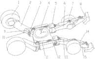
步行式底盘用于挖掘机的步行和行驶,如图1所示,其结构主要由后轮1、后腿2、后关节3、底座4、前关节5、前腿6、前轮7、前臂15和前爪8组成。前后轮采用液压马达驱动。后轮转向采用后轮转向油缸9驱动,后腿摆动与升降分别采用后腿摆动油缸 10和后腿升降油缸11驱动,前腿摆动与升降分别采用前腿摆动油缸12和前腿升降油缸 13驱动,前臂升降采用前臂升降油缸14驱动。步行式底盘为左右对称结构。The walking chassis is used for walking and driving of the excavator. As shown in Figure 1, its structure is mainly composed of
步行式底盘具有13个自由度,包括左、右后腿上下、左右摆动4个自由度,左、右前腿上下、左右摆动4个自由度,以及左右前腿中前臂升降2个自由度,前轮和后轮 (左右轮液压油路串连)驱动各1个自由度,后轮转向(左右轮液压油路串连)1个自由度。步行式底盘一般采用前腿与后轮配合转向,可以实现直线行驶和蟹行功能。The walking chassis has 13 degrees of freedom, including 4 degrees of freedom for left and right rear legs to swing up and down, left and right, 4 degrees of freedom for left and right front legs to swing up and down, left and right, and 2 degrees of freedom for forearm lifting in the left and right front legs. The wheel and the rear wheel (the left and right wheel hydraulic oil circuits are connected in series) are driven with one degree of freedom each, and the rear wheel steering (the left and right wheel hydraulic oil circuits are connected in series) have one degree of freedom. The walking chassis generally uses the front legs and the rear wheels to cooperate with the steering, which can realize the functions of straight driving and crab walking.
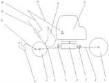
工作装置用于挖掘作业和辅助步行式底盘行走,如图2所示,其结构主要由安装在步行式底盘上的回转平台23、动臂22、斗杆20、伸缩臂18和铲斗16组成。其中回转平台采用液压马达驱动(回转平台内部);动臂、斗杆、伸缩臂和挖斗分别由动臂油缸 25、斗杆油缸21、伸缩臂油缸19和铲斗油缸17驱动。The working device is used for excavation and assisting the walking of the walking chassis. As shown in Figure 2, its structure is mainly composed of a
工作装置具有5个自由度,包括动臂1个摆动自由度、斗杆1个摆动自由度、伸缩臂1个平移自由度、铲斗1个摆动自由度和回转平台1个回转自由度。The working device has five degrees of freedom, including one swinging degree of freedom for the boom, one swinging degree of freedom for the stick, one translational degree of freedom for the telescopic arm, one swinging degree of freedom for the bucket and one rotational degree of freedom for the slewing platform.
为了便于表达,将步行式挖掘机结构图转化为运动简图,其行驶状态的主视图和俯视图分别如图3、图4所示。For the convenience of expression, the structure diagram of the walking excavator is converted into a motion diagram, and the front view and top view of the driving state are shown in Figure 3 and Figure 4, respectively.
步行式底盘是一种由多组关节、腿、轮连接而成的多自由度结构系统,其4条步行腿与具有伸缩功能的工作装置配合起来,相当于一个具有5条腿的步行行走机构,使得步行式挖掘机具有越障、爬坡、涉水、跨越壕沟等特殊功能,可在复杂地形环境下进行步行和作业。由于步行式挖掘机的控制自由度多,其步行时操作控制复杂,对驾驶员操作技能要求高。The walking chassis is a multi-degree-of-freedom structural system composed of multiple sets of joints, legs and wheels. Its four walking legs are matched with a working device with telescopic function, which is equivalent to a walking mechanism with five legs. , so that the walking excavator has special functions such as crossing obstacles, climbing, wading, and crossing trenches, and can walk and operate in complex terrain environments. Because the walking excavator has many degrees of control freedom, its operation and control when walking is complicated, and it requires high operating skills of the driver.
步行式挖掘机行驶速度较低,长距离机动时一般采用专用车辆运输。其中的运输车车厢空间狭窄,仅能容纳步行式挖掘机运输。因此,步行式挖掘机上、下运输车时,需要对其进行准确定位,对驾驶员的要求非常高。操作过程中稍有疏忽,就易造成运输车损伤和步行式挖掘机倾翻等安全事故。The walking speed of the walking excavator is low, and special vehicles are generally used for long-distance maneuvering. One of the transporter compartments has a narrow space and can only accommodate walking excavators. Therefore, when the walking excavator gets on and off the transport vehicle, it needs to be accurately positioned, and the requirements for the driver are very high. A little negligence in the operation process can easily cause safety accidents such as damage to the transport vehicle and tipping of the walking excavator.
发明内容SUMMARY OF THE INVENTION
本发明要解决的问题是提供一种步行式挖掘机自行上下运输车控制方法。采用这种控制方法,可避免运输车损伤和步行式挖掘机倾翻等安全事故的发生。The problem to be solved by the present invention is to provide a control method for a walking excavator to get on and off a transport vehicle by itself. With this control method, safety accidents such as damage to the transport vehicle and tipping over of the walking excavator can be avoided.
本发明要解决的上述问题有以下技术方案实现:The above-mentioned problems to be solved by the present invention are realized by the following technical solutions:
本发明的步行式挖掘机自行上下运输车控制方法特点是依次包括以下步骤:The characteristic of the control method for the self-driving excavator getting on and off the transport vehicle of the present invention is that it includes the following steps in sequence:
(1).设置传感器和控制器(1). Set up sensors and controllers
a.在步行式挖掘机底盘的后轮转向油缸、后腿摆动油缸、后腿升降油缸、前腿摆动油缸、前腿升降油缸和前臂升降油缸上均设置一个用于测量它们的活塞杆行程和位置的第一位移传感器,在两个后腿升降油缸和两个前腿升降油缸的油路中均设置一个用于测量步行腿受压状态的第一压力传感器;所述第一位移传感器和第一压力传感器均借助导线与控制器相连。a. On the rear wheel steering cylinder, rear leg swing cylinder, rear leg lift cylinder, front leg swing cylinder, front leg lift cylinder and forearm lift cylinder of the walking excavator chassis are all set up to measure their piston rod stroke and The position of the first displacement sensor, a first pressure sensor for measuring the compression state of the walking leg is set in the oil circuits of the two rear leg lifting cylinders and the two front leg lifting cylinders; the first displacement sensor and the third A pressure sensor is connected to the controller by means of wires.
b.在工作装置的动臂油缸、斗杆油缸、伸缩臂油缸和铲斗油缸中均设置一个用于测量其活塞杆行程和位置的第二位移传感器,在铲斗油缸的油路中设置用于测量工作装置受力状态的第二压力传感器。所述第二位移传感器和第二压力传感器均借助导线与控制器相连。b. A second displacement sensor for measuring the stroke and position of the piston rod is set in the boom cylinder, stick cylinder, telescopic arm cylinder and bucket cylinder of the working device, and a second displacement sensor is set in the oil circuit of the bucket cylinder. The second pressure sensor is used to measure the force state of the working device. Both the second displacement sensor and the second pressure sensor are connected to the controller by means of wires.
c.在回转平台上设置一个用于测量其相对于初始位置旋转角度的转角传感器,在回转平台中心的纵向和横向均设置一个用于测量其俯仰角和侧倾角的水平角度传感器。所述转角传感器和水平角度传感器均借助导线与控制器相连。c. Set a rotation angle sensor on the rotary platform for measuring its rotation angle relative to the initial position, and set up a horizontal angle sensor for measuring its pitch angle and roll angle in both the longitudinal and lateral directions of the center of the rotary platform. Both the rotation angle sensor and the horizontal angle sensor are connected with the controller by means of wires.
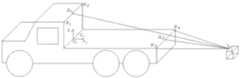
d.在底座4的后侧中心设置一个测距传感器S1,该测距传感器借助导线与控制器相连。以运输车前挡板的上边左端R1和上边右端R2及运输车平台的后边左端R3和后边右端R4均作为测距参考点,通过测量测距参考点与测距传感器S1间的距离来获得步行式挖掘机相对于测距参考点的位置和姿态。d. A distance measuring sensor S1 is arranged in the center of the rear side of the
(2).建立步式挖掘机空间数学模型(2). Establish a spatial mathematical model of the walking excavator
由控制器中的微处理器建立并计算步行式挖掘机数学模型,识别运输车空间位置及实现步行式挖掘机上下运输车步态控制。The microprocessor in the controller establishes and calculates the mathematical model of the walking excavator, identifies the space position of the transporter and realizes the gait control of the walking excavator up and down the transporter.
(3).由控制器中的微处理器对步行式挖掘机与运输车距离调整进行规划运算(3). The microprocessor in the controller performs the planning calculation on the distance adjustment between the walking excavator and the transport vehicle
先使步行式挖掘机的纵向中心平面xoz与运输车平台的纵向中心平面x1o1z1相重合,其中,上车时步行式挖掘机的后轮朝向运输车方向;First, make the longitudinal center plane xoz of the walking excavator coincide with the longitudinal center plane x1 o1 z1 of the platform of the transport vehicle, wherein the rear wheel of the walking excavator faces the direction of the transport vehicle when getting on the vehicle;
再识别运输车平台的相对位置;Re-identify the relative position of the transport vehicle platform;
以运输车平台的前挡板上边中心点为A1、运输车平台的后边中心点为A2,根据底座的后侧中心上的测距传感器S1到运输车平台前挡板的上边左端R1的距离和运输车平台的后边左端R3的距离,已知LR1R2、LR3R4值,得到运输车前挡板的上边中心点A1、运输车平台的后边中心点A2相对于底座4后侧中心的测距传感器S1的距离分别为:Taking the upper center point of the front baffle of the transport vehicle platform as A1 and the rear center point of the transport vehicle platform as A2, according to the distance and The distance between the rear left end R3 of the transport vehicle platform, the known values of LR1R2 and LR3R4 , obtain the distance measuring sensor of the upper center point A1 of the front baffle of the transport vehicle and the rear center point A2 of the transport vehicle platform relative to the center of the rear side of the


依据
然后,调整步行式挖掘机与运输车平台的相对位置。判断LS1A2和设定的可上车距离L 的关系:若LS1A2>L,则步行式挖掘机向运输车方向移动的距离为LS1A2-L。若LS1A2=L,则步行式挖掘机保持不动。若LS1A2<L,则步行式挖掘机向运输车反方向移动的距离为L-LS1A2。Then, adjust the relative position of the walking excavator and the platform of the transporter. Determining the relationship between LS1A2 and the set accessible distance L: if LS1A2 >L, the distance the walking excavator moves in the direction of the transport vehicle is LS1A2 -L. If LS1A2 =L, the walking excavator remains stationary. If LS1A2 <L, the distance that the walking excavator moves in the opposite direction to the transport vehicle is LLS1A2 .
依据步行式挖掘机的底座4后侧中心的测距传感器S1,识别步行式挖掘机与运输车的相对位置。依据设定的可上车距离L,驱动前轮和后轮来对步行式挖掘机与运输车之间的位置进行调整。According to the distance measuring sensor S1 in the center of the rear side of the
(4).进行上车步态规划运算(4). Carry out the gait planning calculation for getting on the vehicle
(5).进行下车步态规划运算。(5). Carry out the calculation of getting off gait planning.
其中:in:
所述步行式挖掘机空间数学模型包括:The space mathematical model of the walking excavator includes:
(1)利用机器人建模理论,以底座回转中心与其回转支承上平面交点为坐标原点o,以过坐标原点o的步行式挖掘机的行驶方向为x轴,且方向向前;以过坐标原点o、垂直于回转支承上平面为z轴,且方向向上;以过坐标原点o、与x轴和z轴相互垂直的轴为 y轴,且方向向左,建立o-xyz基坐标系;同时,建立挖掘机的左前腿、右前腿、左后腿、右后腿和工作装置的铲斗、伸缩臂、斗杆、动臂的参考坐标系,利用步行挖掘机的结构参数和布置在其各个执行元件驱动油缸上的第一位移传感器、第二位移传感器和水平角度传感器,获得各运动部件的位置状态参数,确定各运动部件的运动状态;再利用机器人空间坐标变换理论,建立步行式挖掘机的三维空间数学模型。(1) Using the robot modeling theory, take the intersection of the base rotation center and the upper plane of the slewing bearing as the coordinate origin o, and take the traveling direction of the walking excavator passing through the coordinate origin o as the x-axis, and the direction is forward; o. The upper plane perpendicular to the slewing bearing is the z-axis, and the direction is upward; the o-xyz base coordinate system is established by taking the coordinate origin o and the axis perpendicular to the x-axis and the z-axis as the y-axis, and the direction is to the left; , establish the reference coordinate system of the left front leg, right front leg, left rear leg, right rear leg of the excavator and the bucket, telescopic arm, stick, and boom of the working device, and use the structural parameters and layout of the walking excavator. The actuator drives the first displacement sensor, the second displacement sensor and the horizontal angle sensor on the oil cylinder to obtain the position state parameters of each moving part and determine the motion state of each moving part; then use the robot space coordinate transformation theory to establish a walking excavator 3D space mathematical model.
(2)利用第一压力传感器和第二压力传感器,获得步行式挖掘机的触觉信息,以便感知左前腿、右前腿、左后腿、右后腿和工作装置与地面、运输车或障碍物的接触情况。(2) Using the first pressure sensor and the second pressure sensor to obtain the tactile information of the walking excavator, so as to sense the relationship between the left front leg, the right front leg, the left rear leg, the right rear leg and the working device and the ground, the transport vehicle or the obstacle contact situation.
(3)利用所述三维空间数学模型和触觉信息,确定运动中的步行式挖掘机任意点的空间位置并对其姿态进行判别。(3) Using the three-dimensional spatial mathematical model and tactile information, determine the spatial position of any point of the walking excavator in motion and judge its posture.
(4)利用所述三维空间数学模型,对步行式挖掘机的作业对象、障碍物等进行空间参数测量,并判断作业对象和障碍物与步行式挖掘机的相对空间位置。(4) Using the three-dimensional spatial mathematical model, measure the spatial parameters of the working objects and obstacles of the walking excavator, and judge the relative spatial positions of the working objects and obstacles and the walking excavator.
(5)利用所述三维空间数学模型、回转平台上的水平角度传感器测量的参数和第一压力传感器,对步行式挖掘机所处的地形情况进行触觉探测,并确定步行式挖掘机的重心位置参数。(5) Using the three-dimensional space mathematical model, the parameters measured by the horizontal angle sensor on the rotary platform, and the first pressure sensor, tactile detection is performed on the terrain where the walking excavator is located, and the position of the center of gravity of the walking excavator is determined. parameter.
所述上车规划运算包括:The boarding planning operation includes:
(1)进行后轮上车与姿态调整(1) Carry out rear wheel loading and attitude adjustment
收缩斗杆,伸长动臂油缸,抬升工作装置,并伸长伸缩臂油缸,使铲斗位于运输车平台后边之前的50~100cm正上方。然后,收缩动臂油缸,使铲斗的斗齿置于运输车平台上。再收缩前臂升降油缸至最短,使前爪处于最高状态。Retract the stick, extend the boom cylinder, lift the working device, and extend the telescopic boom cylinder so that the bucket is located 50-100cm above the rear of the transport vehicle platform. Then, retract the boom cylinder so that the bucket teeth rest on the carrier platform. Then retract the forearm lifting cylinder to the shortest, so that the front paws are in the highest state.
收缩动臂油缸和伸缩臂油缸,并驱动前轮使步行式挖掘机向运输车方向移动,使步行挖掘机的后轮抬起至运输车平台之上。The boom cylinder and the telescopic boom cylinder are retracted, and the front wheels are driven to move the walking excavator toward the transport vehicle, so that the rear wheels of the walking excavator are lifted above the transport vehicle platform.
调整后腿摆动油缸,使后腿向内合拢至最小状态。Adjust the rear leg swing cylinder to make the rear legs close inward to the smallest state.
进一步收缩动臂油缸、伸长斗杆油缸的同时,驱动前轮使步行式挖掘机继续向运输车方向移动,直至使后轮位于运输车后侧上方。继续收缩伸缩油缸,使后轮落到运输车平台后边之前的50~100cm处,从而实现了后轮上车。While further retracting the boom cylinder and extending the stick cylinder, drive the front wheels to make the walking excavator continue to move toward the transporter until the rear wheels are positioned above the rear side of the transporter. Continue to shrink the telescopic oil cylinder, so that the rear wheel falls 50-100cm before the rear of the transport vehicle platform, so that the rear wheel can get on the vehicle.
(2)进行前轮上车与姿态调整:(2) Carry out front wheel loading and attitude adjustment:
先使步行式挖掘机的后轮位于运输车平台上,在伸长动臂油缸使铲斗向上抬起的同时,收缩斗杆油缸使斗杆也向上抬起。驱动回转平台的液压马达旋转180度,使工作装置置于步行挖掘机的正前方。伸长斗杆油缸至最长位置,收缩动臂油缸,使铲斗的斗底置于地面上。First place the rear wheel of the walking excavator on the platform of the transport vehicle, and while extending the boom cylinder to lift the bucket upwards, retract the stick cylinder to lift the stick up. The hydraulic motor that drives the slewing platform rotates 180 degrees, so that the working device is placed directly in front of the walking excavator. Extend the stick cylinder to the longest position and retract the boom cylinder so that the bottom of the bucket is on the ground.
再依次收缩斗杆油缸、伸长动臂油缸,驱动后轮,使步行式挖掘机的前轮抬起并后移。Then shrink the stick cylinder and extend the boom cylinder in turn to drive the rear wheel, so that the front wheel of the walking excavator is lifted and moved backward.
依据测试距离LS1A1和步行式挖掘机的数学模型,继续收缩斗杆油缸,并伸长伸缩臂油缸,使步行式挖掘机向运输车前挡板方向移动,直至使后轮到达运输车平台前挡板跟前。According to the test distance LS1A1 and the mathematical model of the walking excavator, continue to shrink the stick cylinder and extend the telescopic arm cylinder to move the walking excavator toward the front baffle of the transport vehicle until the rear wheels reach the front of the transport vehicle platform. front of the bezel.
收缩伸缩臂油缸,使步行式挖掘机前轮落在运输车平台的同时,收缩两个前腿升降油缸和两个后腿升降油缸,使步行式挖掘机的底座也置于运输车平台上。伸长铲斗油缸到最长处,收缩伸缩臂油缸至最短位置,伸长斗杆油缸到最长处,收缩动臂油缸,降低工作装置高度,使铲斗的斗底置于运输车平台上,从而实现了前轮上车。Retract the telescopic arm cylinder so that the front wheel of the walking excavator falls on the platform of the transport vehicle, and at the same time, shrink the two front leg lifting cylinders and the two rear leg lifting cylinders, so that the base of the walking excavator is also placed on the transport vehicle platform. Extend the bucket cylinder to the longest position, retract the telescopic arm cylinder to the shortest position, extend the stick cylinder to the longest position, retract the boom cylinder, lower the height of the working device, and place the bottom of the bucket on the platform of the transport vehicle, thereby Realized the front wheel on the car.
(5)进行下车步态规划运算。(5) Carry out the calculation of getting off gait planning.
所述下车规划运算包括:The drop-off planning operation includes:
(1)姿态调整与前轮着地(1) Attitude adjustment and front wheel landing
a.同时伸长两个前腿升降油缸、两个后腿升降油缸,使步行式挖掘机的后腿和前腿与运输车平台的上表面保持平行,底座与运输车平台的上表面也保持平行。a. Extend the two front leg lifting cylinders and the two rear leg lifting cylinders at the same time, so that the rear and front legs of the walking excavator are kept parallel to the upper surface of the transporter platform, and the base and the upper surface of the transporter platform are also kept parallel parallel.
b.依次伸长动臂油缸至其行程的一半处,伸长伸缩臂油缸至最长位置,缩短斗杆油缸和铲斗油缸至最短位置,使工作装置向运输车平台后方伸出。b. Extend the boom cylinder to the half of its stroke in turn, extend the telescopic boom cylinder to the longest position, shorten the stick cylinder and bucket cylinder to the shortest position, so that the working device extends to the rear of the transport vehicle platform.
c.收缩动臂油缸,使铲斗的斗齿置于地面上。进一步收缩动臂油缸,使前轮脱离运输车平台。c. Retract the boom cylinder so that the bucket teeth of the bucket are placed on the ground. Retract the boom cylinder further to disengage the front wheel from the hauler platform.
d.驱动后轮,并依次收缩伸缩臂油缸、伸长斗杆油缸和铲斗油缸,使步行式挖掘机向运输车的后方移动,直至使后轮运动至运输车平台的后边缘。然后,收缩动臂油缸,使前轮着地,完成了前轮下车过程。d. Drive the rear wheel, and shrink the telescopic arm cylinder, the extension stick cylinder and the bucket cylinder in turn, so that the walking excavator moves to the rear of the transport vehicle until the rear wheel moves to the rear edge of the transport vehicle platform. Then, retract the boom cylinder to make the front wheel touch the ground, completing the process of getting off the front wheel.
(2)姿态调整与后轮着地(2) Attitude adjustment and rear wheel landing
a.伸长动臂油缸,收缩斗杆油缸,使斗杆向上抬起。然后,驱动回转平台的液压马达旋转180度,使工作装置置于步行式挖掘机的正后方。再伸长斗杆油缸,收缩动臂油缸,使铲斗的斗齿置于运输车平台后边之前的50~100cm处。a. Extend the boom cylinder and retract the stick cylinder to lift the stick upward. Then, the hydraulic motor that drives the swing platform rotates 180 degrees, so that the work equipment is placed directly behind the walking excavator. Extend the stick cylinder and shrink the boom cylinder, so that the bucket teeth of the bucket are placed 50-100cm behind the platform of the transport vehicle.
b.依次伸长伸缩臂油缸、斗杆油缸和动臂油缸,驱动前轮,使步行式挖掘机向前移动并使后轮距运输车平台后边50~100cm处。再调整后腿摆动油缸,使后腿向外伸展并调整至行驶状态。b. Extend the telescopic arm oil cylinder, stick oil cylinder and boom oil cylinder in turn to drive the front wheel to move the walking excavator forward and keep the rear wheel at a distance of 50-100cm from the rear of the transport vehicle platform. Then adjust the rear leg swing cylinder to extend the rear leg and adjust it to the driving state.
c.进一步伸长动臂油缸,使后轮着地。同时,缩短伸缩臂油缸,使铲斗脱离运输车平台;驱动回转平台的液压马达旋转180度,使工作装置置于步行式挖掘机的正前方。然后,调整工作装置的动臂油缸、斗杆油缸、伸缩臂油缸和铲斗油缸,使工作装置处于行驶状态,完成了下车过程。c. Further extend the boom cylinder to make the rear wheel touch the ground. At the same time, shorten the telescopic arm oil cylinder to make the bucket separate from the platform of the transport vehicle; the hydraulic motor driving the slewing platform rotates 180 degrees, so that the working device is placed directly in front of the walking excavator. Then, adjust the boom oil cylinder, stick oil cylinder, telescopic arm oil cylinder and bucket oil cylinder of the working device so that the working device is in a driving state, and the process of getting off the vehicle is completed.
由以上方案可以看出,由于本发明的步行式挖掘机自行上下运输车控制方法包括依次包括设置传感器和控制器、建立步式挖掘机空间数学模型、由控制器中的微处理器对步行式挖掘机与运输车距离调整进行规划运算、进行上车步态规划运算和进行下车步态规划运算等步骤。当控制器中的微处理器获得上车或下车指令时,由依据步行式挖掘机传感器获得的信息和步行式挖掘机的空间数学模型,确定步行式挖掘机的初始状态。然后,由控制器中的微处理器依据上(或下)车步态规划算法,求解第一个序列控制指令,通过控制器、电液控制阀组,控制步行式挖掘机的执行元件(指步行腿、工作装置上的各个液压驱动油缸、驱动轮液压马达、回转平台液压驱动马达)动作。再由执行元件及步行式挖掘机上的第一位移传感器、第二位移传感器、第一压力传感器、第二压力传感器、测距传感器、转角传感器、水平角度传感器获得状态和位置信息,并反馈给控制器的微处理器中的步态规划算法模块,依据步态算法计算下一步步态指令。如此反复,实现步行式挖掘机自行上下运输车过程。与背景技术相比,降低了对驾驶员的要求,避免了因驾驶员操作过程中的疏忽而造成的运输车损伤和步行式挖掘机倾翻等事故的发生。It can be seen from the above scheme that the control method of the walking excavator self-loading and unloading transport vehicle of the present invention includes sequentially including setting a sensor and a controller, establishing a spatial mathematical model of the walking excavator, and controlling the walking type excavator by the microprocessor in the controller. The distance between the excavator and the transport vehicle is adjusted to perform planning operations, performing gait planning operations for getting on the vehicle, and performing planning operations for getting off the vehicle. When the microprocessor in the controller obtains an instruction for getting on or off the vehicle, the initial state of the walking excavator is determined based on the information obtained from the walking excavator sensor and the space mathematical model of the walking excavator. Then, the microprocessor in the controller solves the first sequence control command according to the gait planning algorithm of the up (or down) vehicle, and controls the actuator (refer to the controller and the electro-hydraulic control valve group) of the walking excavator. The walking legs, various hydraulic drive cylinders on the working device, the hydraulic motor of the driving wheel, and the hydraulic drive motor of the rotary platform) act. Then, the state and position information are obtained by the actuator and the first displacement sensor, second displacement sensor, first pressure sensor, second pressure sensor, distance measuring sensor, rotation angle sensor, and horizontal angle sensor on the walking excavator, and fed back to the control The gait planning algorithm module in the microprocessor of the device calculates the next step gait instruction according to the gait algorithm. Repeatedly, the process of getting on and off the transport vehicle by the walking excavator is realized. Compared with the background technology, the requirements for the driver are reduced, and accidents such as the damage of the transport vehicle and the overturning of the walking excavator caused by the negligence of the driver during the operation are avoided.
附图说明Description of drawings
图1是步行式挖掘机立体示意图;Fig. 1 is a three-dimensional schematic diagram of a walking excavator;
图2是步行式挖掘机底盘的立体示意图;;Figure 2 is a perspective view of a walking excavator chassis;
图3是步行式挖掘机行驶状态示意图;Fig. 3 is a schematic diagram of the running state of the walking excavator;
图4是图3的俯视示意图;Fig. 4 is the top schematic view of Fig. 3;
图5是测距原理示意图;Figure 5 is a schematic diagram of the principle of ranging;
图6是步行式挖掘机上车前的状态示意图;Fig. 6 is the state schematic diagram of the walking excavator before getting on the vehicle;
图7a~7d是后轮上车与姿态调整过程示意图;Figures 7a-7d are schematic diagrams of the rear wheel getting on the vehicle and the attitude adjustment process;
图8a~8d是前轮上车与姿态调整过程示意图;Figures 8a to 8d are schematic diagrams of the front wheel getting on the vehicle and the attitude adjustment process;
图9是本发明的步行式挖掘机自行上下运输车控制方法原理图。FIG. 9 is a schematic diagram of a control method for a walk-behind excavator to get on and off a transport vehicle by itself according to the present invention.
具体实施方式Detailed ways
如图1至图9所示,本发明的步行式挖掘机自行上下运输车控制方法依次包括以下步骤:As shown in FIG. 1 to FIG. 9 , the control method for the self-driving excavator to get on and off the transport vehicle of the present invention includes the following steps in sequence:
一.设置传感器和控制器,见图1~图41. Set up sensors and controllers, see Figure 1 to Figure 4
1.在步行式挖掘机底盘的后轮转向油缸9、后腿摆动油缸10、后腿升降油缸11、前腿摆动油缸12、前腿升降油缸13和前臂升降油缸14上均设置一个用于测量它们的活塞杆行程和位置的第一位移传感器,在两个后腿升降油缸11和两个前腿升降油缸13的油路中均设置一个用于测量步行腿受压状态的第一压力传感器。所述第一位移传感器和第一压力传感器均借助导线与控制器相连。1. On the rear wheel steering cylinder 9, rear
2.在工作装置的动臂油缸25、斗杆油缸21、伸缩臂油缸19和铲斗油缸17中均设置一个用于测量其活塞杆行程和位置的第二位移传感器,在铲斗油缸17的油路中设置用于测量工作装置受力状态的第二压力传感器;所述第二位移传感器和第二压力传感器均借助导线与控制器相连。2. A second displacement sensor for measuring the stroke and position of the piston rod is provided in the
3.在回转平台23上设置一个用于测量其相对于初始位置旋转角度的转角传感器,在回转平台23中心的纵向和横向均设置一个用于测量其俯仰角和侧倾角的水平角度传感器。所述转角传感器和水平角度传感器均借助导线与控制器相连。3. A rotation angle sensor is provided on the
4.在底座4的后侧中心上设置测距传感器S1,该测距传感器借助导线与控制器相连。以运输车前挡板的上边左端R1和上边右端R2及运输车平台的后边左端R3和后边右端R4均作为一个测距参考点,通过测量这些测距参考点与测距传感器S1间的距离来获得这些测距参考点相对于步行挖掘机的位置和姿态。4. A distance measuring sensor S1 is arranged on the center of the rear side of the
二.建立步式行挖掘机空间数学模型2. Establish a spatial mathematical model of the walking excavator
1.利用机器人建模理论,以底座4回转中心及其回转支承为坐标原点o(见图5),以过坐标原点o的步行式挖掘机的行驶方向为x轴,且方向向前。以过坐标原点o、垂直于回转支承上平面为z轴,且方向向上。以过坐标原点o、与x轴和z轴相互垂直的轴为y 轴,且方向向左,建立o-xyz基坐标系。同时,建立挖掘机的左前腿、右前腿、左后腿、右后腿和工作装置的铲斗、伸缩臂、斗杆、动臂的参考坐标系,利用步行挖掘机的结构参数和布置在其各个执行元件驱动油缸上的第一位移传感器、第二位移传感器和水平角度传感器,获得各运动部件的位置状态参数,确定各运动部件的运动状态。再利用机器人空间坐标变换理论,建立步行式挖掘机的三维空间数学模型;1. Using the robot modeling theory, take the slewing center of the
2.利用第一压力传感器和第二压力传感器,获得步行式挖掘机的触觉信息,以便感知左前腿、右前腿、左后腿、右后腿与地面、运输车或障碍物的接触情况。2. Using the first pressure sensor and the second pressure sensor to obtain the tactile information of the walking excavator, so as to sense the contact situation of the left front leg, the right front leg, the left rear leg, and the right rear leg with the ground, a transport vehicle or an obstacle.
3.利用所述三维空间数学模型和触觉信息,确定运动中的步行式挖掘机任意点的空间位置并对其姿态进行判别。3. Using the three-dimensional spatial mathematical model and tactile information, determine the spatial position of any point of the walking excavator in motion and judge its posture.
4.利用所述三维空间数学模型,对步行式挖掘机的作业对象、障碍物等进行空间参数测量,并判断作业对象、障碍物的相对空间位置。4. Using the three-dimensional spatial mathematical model, measure the spatial parameters of the working objects and obstacles of the walking excavator, and judge the relative spatial positions of the working objects and obstacles.
5.利用所述三维空间数学模型、回转平台23上的水平角度传感器测量的参数和第一压力传感器,对步行式挖掘机所处的地形情况进行触觉探测,并确定步行式挖掘机的重心位置参数。5. Using the three-dimensional mathematical model, the parameters measured by the horizontal angle sensor on the
三.由控制器中的微处理器对步行式挖掘机的上下运输车进行规划运算3. The microprocessor in the controller performs the planning operation on the upper and lower transport vehicles of the walking excavator
先使步行式挖掘机的纵向平面xoz(见图5、图6)与运输车平台的纵向中心平面x1o1z1 (见图5)相重合,其中,上车时步行式挖掘机的后轮朝向运输车方向(见图6)。First, make the longitudinal plane xoz of the walking excavator (see Figure 5 and Figure 6) coincide with the longitudinal center plane x1 o1 z1 (see Figure 5) of the platform of the transport vehicle. The rear wheels are facing the direction of the transporter (see Figure 6).
再识别运输车平台的相对位置。Re-identify the relative position of the transporter platform.
以运输车平台的前挡板的上边中心点为A1、运输车平台的后边中心点为A2,根据底座4的后侧中心上的测距传感器S1到运输车平台的后边左端R3的距离(见图5),已知LR1R2、LR3R4值,得到运输车前挡板的上边中心点A1、运输车平台的后边中心点A2相对于底座4的后侧中心上的测距传感器S1的距离分别为:Taking the upper center point of the front baffle of the transport vehicle platform as A1 and the rear center point of the transport vehicle platform as A2, according to the distance from the distance sensor S1 on the center of the rear side of the


依据
然后,调整步行式挖掘机与运输车平台的相对位置;判断LS1A2和设定的可上车距离 L的关系:若LS1A2>L,则步行式挖掘机向运输车方向移动的距离为LS1A2-L;若LS1A2=L,则步行式挖掘机保持不动;若LS1A2<L,则步行式挖掘机向运输车反方向移动的距离为 L-LS1A2;Then, adjust the relative position of the walking excavator and the transport vehicle platform; determine the relationship between LS1A2 and the set distance L: if LS1A2 > L, the distance the walking excavator moves in the direction of the transport vehicle is LS1A2 -L; if LS1A2 =L, the walking excavator remains stationary; if LS1A2 <L, the distance that the walking excavator moves in the opposite direction of the transport vehicle is LLS1A2 ;
然后,依据步行式挖掘机底座4的后侧中心上的测距传感器S1,识别步行式挖掘机与运输车的相对位置。依据规定可上车距离L,驱动前轮7和后轮1来对步行式挖掘机与运输车之间的位置进行调整。Then, according to the distance measuring sensor S1 on the center of the rear side of the walking-
四.进行上车步态规划运算4. Carry out the gait planning calculation for getting on the train
1.进行后轮上车与姿态调整:1. Carry out rear wheel loading and attitude adjustment:
收缩斗杆21,伸长动臂油缸25,抬升工作装置,并伸长伸缩臂油缸19,使铲斗位于运输车平台后边之前的50~100cmm正上方;然后,收缩动臂油缸25,使铲斗的斗齿置于运输车平台上;再收缩前臂升降油缸14至最短,使前爪8处于最高状态(见图7a);Retract the
收缩动臂油缸25和伸缩臂油缸19,并驱动前轮7使步行式挖掘机向运输车方向移动,使步行挖掘机的后轮1抬起至运输车平台之上(见图7b);Retract the
调整后腿摆动油缸10,使后腿2向内合拢至最小状态(见图7c);Adjust the rear
进一步收缩动臂油缸25、伸长斗杆油缸21的同时,驱动前轮7使步行式挖掘机继续向运输车方向移动,直至使后轮1位于运输车后侧上方。继续收缩伸缩油缸19,使后轮落到运输车平台后边之前的50~100cm处,从而实现了后轮上车。While further retracting the
2.进行前轮上车与姿态调整:2. Carry out front wheel loading and attitude adjustment:
先使步行式挖掘机的后轮1位于运输车平台上,在伸长动臂油缸25使铲斗16向上抬起的同时,收缩斗杆油缸21使斗杆20也向上抬起;驱动回转平台23的液压马达旋转180度,使工作装置置于步行挖掘机的正前方。伸长斗杆油缸21至最长位置,收缩动臂油缸 25,使铲斗16的斗底置于地面上(图8a);Firstly, the
再依次收缩斗杆油缸21、伸长动臂油缸25,驱动后轮1,使步行式挖掘机的前轮7抬起并后移(图8b);Then shrink the
依据测试距离LS1A1和步行式挖掘机的数学模型,继续收缩斗杆油缸21,并伸长伸缩臂油缸19,使步行式挖掘机向运输车前挡板方向移动,直至使后轮1到达运输车平台前挡板跟前(见图8c);According to the test distance LS1A1 and the mathematical model of the walking excavator, continue to shrink the
收缩伸缩臂油缸19,使步行式挖掘机前轮7落在运输车平台的同时,收缩两个前腿升降油缸13和两个后腿升降油缸11,使步行式挖掘机的底座4也置于运输车平台上。伸长铲斗油缸17到最长处,收缩伸缩臂油缸19至最短位置,伸长斗杆油缸21到最长处,收缩动臂油缸25,降低工作装置高度,使铲斗的斗底置于运输车平台上(见图8d),从而实现了前轮上车。Retract the
五.进行下车步态规划运算5. Carry out the calculation of getting off gait planning
1.姿态调整与前轮着地:1. Attitude adjustment and front wheel landing:
(1)同时伸长两个前腿升降油缸12、两个后腿升降油缸11,使步行式挖掘机的后腿2和前腿6与运输车平台的上表面保持平行,底座4与运输车平台的上表面也保持平行;(1) Extend the two front
(2)依次伸长动臂油缸25至其行程的一半处,伸长伸缩臂油缸19至最长位置,缩短斗杆油缸21和铲斗油缸17至最短位置,使工作装置向运输车后方伸出;(2) Extend the
(3)收缩动臂油缸25,使铲斗16的斗齿置于地面上。进一步收缩动臂油缸25,使前轮7脱离运输车平台(见图8c);(3) Retract the
(4)驱动后轮1,并依次收缩伸缩臂油缸19、伸长斗杆油缸21和铲斗油缸17,使步行式挖掘机向运输车的后方移动(见图8b),直至使后轮1运动至运输车平台的后边缘。然后,收缩动臂油缸25,使前轮着地(见图8a),完成了前轮下车过程。(4) Drive the
2.姿态调整与后轮着地:2. Attitude adjustment and rear wheel landing:
(1)伸长动臂油缸25,收缩斗杆油缸21,使斗杆20向上抬起。然后,驱动回转平台23的液压马达旋转180度,使工作装置置于步行式挖掘机的正后方。再伸长斗杆油缸 21,收缩动臂油缸25,使铲斗16的斗齿置于运输车平台后边之前的50~100cm处(见图 7d);(1) Extend the
(2)依次伸长伸缩臂油缸19、斗杆油缸21和动臂油缸25,驱动前轮7,使步行式挖掘机向前移动、后轮1距运输车平台后边之前的50~100cm处(见图7b)。再调整后腿摆动油缸10,使后腿2向外伸展并调整至行驶状态;(2) Extend the
(3)进一步伸长动臂油缸25,使后轮1着地。同时,缩短伸缩臂油缸19,使铲斗 16脱离运输车平台。驱动回转平台23的液压马达旋转180度,使工作装置置于步行式挖掘机的正前方。然后,调整工作装置的动臂油缸25、斗杆油缸21、伸缩臂油缸19和铲斗油缸17,使工作装置处于行驶状态(见图3),完成了下车过程。(3) Further extend the
Claims (4)
Translated fromChinese


Priority Applications (1)
| Application Number | Priority Date | Filing Date | Title |
|---|---|---|---|
| CN202010349272.8ACN111576511B (en) | 2020-04-28 | 2020-04-28 | Control method of walking excavator getting up and down by itself |
Applications Claiming Priority (1)
| Application Number | Priority Date | Filing Date | Title |
|---|---|---|---|
| CN202010349272.8ACN111576511B (en) | 2020-04-28 | 2020-04-28 | Control method of walking excavator getting up and down by itself |
Publications (2)
| Publication Number | Publication Date |
|---|---|
| CN111576511Atrue CN111576511A (en) | 2020-08-25 |
| CN111576511B CN111576511B (en) | 2022-03-04 |
Family
ID=72119942
Family Applications (1)
| Application Number | Title | Priority Date | Filing Date |
|---|---|---|---|
| CN202010349272.8AActiveCN111576511B (en) | 2020-04-28 | 2020-04-28 | Control method of walking excavator getting up and down by itself |
Country Status (1)
| Country | Link |
|---|---|
| CN (1) | CN111576511B (en) |
Cited By (4)
| Publication number | Priority date | Publication date | Assignee | Title |
|---|---|---|---|---|
| CN114158454A (en)* | 2021-11-19 | 2022-03-11 | 袁雪鸽 | Anti-toppling supporting device with soil tree mover |
| CN114753432A (en)* | 2022-04-20 | 2022-07-15 | 中联重科土方机械有限公司 | Control method, controller and device for excavator and excavator |
| CN115450278A (en)* | 2022-09-16 | 2022-12-09 | 江苏电子信息职业学院 | Auxiliary digging control method for loader bucket |
| CN115961667A (en)* | 2022-10-17 | 2023-04-14 | 江苏徐工工程机械研究院有限公司 | Excavator control method, controller, control system, excavator and storage medium |
Citations (5)
| Publication number | Priority date | Publication date | Assignee | Title |
|---|---|---|---|---|
| US20010008605A1 (en)* | 2000-01-17 | 2001-07-19 | Richard Schultz | Apparatus for loading a truck box |
| EP1470955A2 (en)* | 2003-04-22 | 2004-10-27 | Liebherr-Hydraulikbagger GmbH | Device for transporting a construction machine, especially an excavator |
| US20180163364A1 (en)* | 2015-04-17 | 2018-06-14 | Hudson Bay Holding B.V. | Safety system for mobile apparatus |
| CN108177582A (en)* | 2017-12-31 | 2018-06-19 | 重庆市合川区川柠农业发展有限公司 | A kind of rice transplanter transport vehicle |
| CN109532633A (en)* | 2018-12-04 | 2019-03-29 | 杨达全 | A kind of agricultural machinery is placed and transport device |
- 2020
- 2020-04-28CNCN202010349272.8Apatent/CN111576511B/enactiveActive
Patent Citations (5)
| Publication number | Priority date | Publication date | Assignee | Title |
|---|---|---|---|---|
| US20010008605A1 (en)* | 2000-01-17 | 2001-07-19 | Richard Schultz | Apparatus for loading a truck box |
| EP1470955A2 (en)* | 2003-04-22 | 2004-10-27 | Liebherr-Hydraulikbagger GmbH | Device for transporting a construction machine, especially an excavator |
| US20180163364A1 (en)* | 2015-04-17 | 2018-06-14 | Hudson Bay Holding B.V. | Safety system for mobile apparatus |
| CN108177582A (en)* | 2017-12-31 | 2018-06-19 | 重庆市合川区川柠农业发展有限公司 | A kind of rice transplanter transport vehicle |
| CN109532633A (en)* | 2018-12-04 | 2019-03-29 | 杨达全 | A kind of agricultural machinery is placed and transport device |
Cited By (6)
| Publication number | Priority date | Publication date | Assignee | Title |
|---|---|---|---|---|
| CN114158454A (en)* | 2021-11-19 | 2022-03-11 | 袁雪鸽 | Anti-toppling supporting device with soil tree mover |
| CN114753432A (en)* | 2022-04-20 | 2022-07-15 | 中联重科土方机械有限公司 | Control method, controller and device for excavator and excavator |
| CN115450278A (en)* | 2022-09-16 | 2022-12-09 | 江苏电子信息职业学院 | Auxiliary digging control method for loader bucket |
| CN115450278B (en)* | 2022-09-16 | 2023-09-22 | 江苏电子信息职业学院 | Auxiliary shoveling control method for loader bucket |
| CN115961667A (en)* | 2022-10-17 | 2023-04-14 | 江苏徐工工程机械研究院有限公司 | Excavator control method, controller, control system, excavator and storage medium |
| CN115961667B (en)* | 2022-10-17 | 2025-09-02 | 江苏徐工工程机械研究院有限公司 | Excavator control method, controller, control system, excavator and storage medium |
Also Published As
| Publication number | Publication date |
|---|---|
| CN111576511B (en) | 2022-03-04 |
Similar Documents
| Publication | Publication Date | Title |
|---|---|---|
| CN111576511B (en) | Control method of walking excavator getting up and down by itself | |
| CN104192221B (en) | A kind of electric drive Hexapod Robot kinetic control system and method | |
| JP6638903B2 (en) | Construction work robot | |
| US10626576B2 (en) | Loader with telescopic lift arm | |
| JP2017014726A (en) | Work support system for work machines | |
| CN114687392B (en) | Wheel track type drilling and grabbing multifunctional integrated device and pole setting operation method | |
| WO2019213246A1 (en) | Automated coupling of an implement to an implement carrier of a power machine | |
| US20170058488A1 (en) | Implement system control device | |
| CN107985443B (en) | Wheeled multi-ground adaptive vehicle and obstacle crossing method thereof | |
| JP2022152454A (en) | Work machine travel system and work machine control method | |
| CN115030243A (en) | System and method for terrain-based control of a self-propelled work vehicle | |
| JP2020133223A (en) | Safety device and construction machine | |
| JPH0784186B2 (en) | Slope running vehicle | |
| KR20230043172A (en) | work machine | |
| CN115562097A (en) | Intelligent control system of crawler-type hydraulic excavator upper and lower non-ladder plate vehicle | |
| JP2018034239A (en) | Mobile robot and creeping movement method thereof | |
| JP3944171B2 (en) | Double arm robot | |
| CN112157662B (en) | Blasting robot | |
| CN112081165B (en) | Land grader and slope control method and device thereof | |
| JP2024030582A (en) | Work machines, systems including work machines, and control methods for work machines | |
| Serón et al. | Terrace climbing of the Alacrane mobile robot with cooperation of its onboard arm | |
| CN117449388B (en) | Construction site leveling operation method and system based on laser guidance and excavator | |
| CN115961667B (en) | Excavator control method, controller, control system, excavator and storage medium | |
| CN222780467U (en) | Self-propelled vehicle frame and working machine having the same | |
| JP7268577B2 (en) | working machine |
Legal Events
| Date | Code | Title | Description |
|---|---|---|---|
| PB01 | Publication | ||
| PB01 | Publication | ||
| SE01 | Entry into force of request for substantive examination | ||
| SE01 | Entry into force of request for substantive examination | ||
| GR01 | Patent grant | ||
| GR01 | Patent grant | ||
| CP03 | Change of name, title or address | ||
| CP03 | Change of name, title or address | Address after:214035 Tonghui West Road, Wuxi City, Jiangsu Province Patentee after:63983 FORCES, PLA Country or region after:China Address before:214035 No. 160, Tonghui West Road, Liangxi District, Wuxi City, Jiangsu Province Patentee before:63983 FORCES, PLA Country or region before:China |