CN111572558A - A Dynamic Control Method for Maximum Envelope of Unmanned Vehicles - Google Patents
A Dynamic Control Method for Maximum Envelope of Unmanned VehiclesDownload PDFInfo
- Publication number
- CN111572558A CN111572558ACN202010249871.2ACN202010249871ACN111572558ACN 111572558 ACN111572558 ACN 111572558ACN 202010249871 ACN202010249871 ACN 202010249871ACN 111572558 ACN111572558 ACN 111572558A
- Authority
- CN
- China
- Prior art keywords
- unmanned vehicle
- controller
- vehicle
- longitudinal
- yaw moment
- Prior art date
- Legal status (The legal status is an assumption and is not a legal conclusion. Google has not performed a legal analysis and makes no representation as to the accuracy of the status listed.)
- Pending
Links
Images


Classifications
- B—PERFORMING OPERATIONS; TRANSPORTING
- B60—VEHICLES IN GENERAL
- B60W—CONJOINT CONTROL OF VEHICLE SUB-UNITS OF DIFFERENT TYPE OR DIFFERENT FUNCTION; CONTROL SYSTEMS SPECIALLY ADAPTED FOR HYBRID VEHICLES; ROAD VEHICLE DRIVE CONTROL SYSTEMS FOR PURPOSES NOT RELATED TO THE CONTROL OF A PARTICULAR SUB-UNIT
- B60W60/00—Drive control systems specially adapted for autonomous road vehicles
- B60W60/001—Planning or execution of driving tasks
- B—PERFORMING OPERATIONS; TRANSPORTING
- B60—VEHICLES IN GENERAL
- B60W—CONJOINT CONTROL OF VEHICLE SUB-UNITS OF DIFFERENT TYPE OR DIFFERENT FUNCTION; CONTROL SYSTEMS SPECIALLY ADAPTED FOR HYBRID VEHICLES; ROAD VEHICLE DRIVE CONTROL SYSTEMS FOR PURPOSES NOT RELATED TO THE CONTROL OF A PARTICULAR SUB-UNIT
- B60W30/00—Purposes of road vehicle drive control systems not related to the control of a particular sub-unit, e.g. of systems using conjoint control of vehicle sub-units
- B60W30/10—Path keeping
- B—PERFORMING OPERATIONS; TRANSPORTING
- B60—VEHICLES IN GENERAL
- B60W—CONJOINT CONTROL OF VEHICLE SUB-UNITS OF DIFFERENT TYPE OR DIFFERENT FUNCTION; CONTROL SYSTEMS SPECIALLY ADAPTED FOR HYBRID VEHICLES; ROAD VEHICLE DRIVE CONTROL SYSTEMS FOR PURPOSES NOT RELATED TO THE CONTROL OF A PARTICULAR SUB-UNIT
- B60W50/00—Details of control systems for road vehicle drive control not related to the control of a particular sub-unit, e.g. process diagnostic or vehicle driver interfaces
- G—PHYSICS
- G06—COMPUTING OR CALCULATING; COUNTING
- G06F—ELECTRIC DIGITAL DATA PROCESSING
- G06F30/00—Computer-aided design [CAD]
- G06F30/10—Geometric CAD
- G06F30/15—Vehicle, aircraft or watercraft design
- G—PHYSICS
- G06—COMPUTING OR CALCULATING; COUNTING
- G06F—ELECTRIC DIGITAL DATA PROCESSING
- G06F30/00—Computer-aided design [CAD]
- G06F30/20—Design optimisation, verification or simulation
- B—PERFORMING OPERATIONS; TRANSPORTING
- B60—VEHICLES IN GENERAL
- B60W—CONJOINT CONTROL OF VEHICLE SUB-UNITS OF DIFFERENT TYPE OR DIFFERENT FUNCTION; CONTROL SYSTEMS SPECIALLY ADAPTED FOR HYBRID VEHICLES; ROAD VEHICLE DRIVE CONTROL SYSTEMS FOR PURPOSES NOT RELATED TO THE CONTROL OF A PARTICULAR SUB-UNIT
- B60W50/00—Details of control systems for road vehicle drive control not related to the control of a particular sub-unit, e.g. process diagnostic or vehicle driver interfaces
- B60W2050/0001—Details of the control system
- B60W2050/0019—Control system elements or transfer functions
- G—PHYSICS
- G06—COMPUTING OR CALCULATING; COUNTING
- G06F—ELECTRIC DIGITAL DATA PROCESSING
- G06F2119/00—Details relating to the type or aim of the analysis or the optimisation
- G06F2119/14—Force analysis or force optimisation, e.g. static or dynamic forces
Landscapes
- Engineering & Computer Science (AREA)
- Physics & Mathematics (AREA)
- Automation & Control Theory (AREA)
- Geometry (AREA)
- Theoretical Computer Science (AREA)
- Transportation (AREA)
- Mechanical Engineering (AREA)
- General Physics & Mathematics (AREA)
- Human Computer Interaction (AREA)
- Evolutionary Computation (AREA)
- Computer Hardware Design (AREA)
- General Engineering & Computer Science (AREA)
- Aviation & Aerospace Engineering (AREA)
- Computational Mathematics (AREA)
- Mathematical Analysis (AREA)
- Mathematical Optimization (AREA)
- Pure & Applied Mathematics (AREA)
- Control Of Position, Course, Altitude, Or Attitude Of Moving Bodies (AREA)
Abstract
Description
Translated fromChinese技术领域technical field
本发明属于无人车与自动驾驶车辆技术领域,具体涉及一种无人车最大包络线动力学控制方法。The invention belongs to the technical field of unmanned vehicles and automatic driving vehicles, and particularly relates to a maximum envelope dynamic control method for unmanned vehicles.
背景技术Background technique
自动驾驶车辆是未来汽车产业的重要发展方向,也是人工智能技术落地的重要领域之一。无人车是指具有自主行为能力并完全省略人类驾驶机构的车辆,具有智能化、线控化、机器人化、多功能化的特点。无人车的使用目的为替代人类执行作业任务,包括但不限于打击、作战、巡逻、侦察、物流、运输、摆渡、配送、清扫等民用或军用任务,在民用或军用领域具有非常广阔的应用前景,是未来智能交通与智慧城市建设的重要组成部分,更是我国新一代陆军装备发展的重要依托。因此,无人车理论与技术的研究对我国国民经济发展与国防安全建设具有重要战略意义。Self-driving vehicles are an important development direction of the future automobile industry and one of the important areas where artificial intelligence technology will be implemented. Unmanned vehicles refer to vehicles that have the ability to act autonomously and completely omit the human driving mechanism. The purpose of using unmanned vehicles is to replace humans to perform tasks, including but not limited to civil or military tasks such as strike, combat, patrol, reconnaissance, logistics, transportation, ferry, distribution, cleaning, etc. It has a very broad application in the civilian or military field. Prospect is an important part of future intelligent transportation and smart city construction, and it is also an important support for the development of my country's new generation of army equipment. Therefore, the research on the theory and technology of unmanned vehicles has important strategic significance for the development of my country's national economy and the construction of national defense and security.
由于特殊的使用功能,无人车完全省略人类操作机构,其底盘必须采用全线控架构,即转向系统、驱动系统及制动系统完全由电子控制系统控制,实现完全的线控转向、线控驱动及线控制动。在另一方面,为了提高无人车的操纵性、稳定性、机动性及可控性,无人车多采用各车轮独立驱动及独立转向技术,使得各车轮的转向角及驱动力都独立可控,大幅增加无人车的执行机构可控自由度,从而满足民用复杂场景或军用场景下的无人车使用需求。Due to the special use function, the unmanned vehicle completely omits the human operating mechanism, and its chassis must adopt a full-wire control structure, that is, the steering system, drive system and braking system are completely controlled by the electronic control system to achieve complete wire-controlled steering and wire-controlled drive. and BBW. On the other hand, in order to improve the maneuverability, stability, maneuverability and controllability of unmanned vehicles, unmanned vehicles mostly use independent driving and independent steering technology of each wheel, so that the steering angle and driving force of each wheel can be independently controlled. It can greatly increase the controllable degree of freedom of the actuator of the unmanned vehicle, so as to meet the needs of unmanned vehicles in complex civil or military scenarios.
在某些特定使用场景尤其是军用场景下,需要充分发挥无人车的动力学性能,以使无人车尽快通过给定路径并完成既定任务,但是,目前传统的无人车动力学控制系统并不能满足充分发挥无人车动力学极限特性的需求,严重制约了高性能无人车在相关场景下的广泛应用。In some specific usage scenarios, especially military scenarios, it is necessary to give full play to the dynamic performance of the unmanned vehicle, so that the unmanned vehicle can pass the given path and complete the given task as soon as possible. However, the current traditional unmanned vehicle dynamics control system It cannot meet the needs of giving full play to the dynamic limit characteristics of unmanned vehicles, which seriously restricts the wide application of high-performance unmanned vehicles in related scenarios.
发明内容SUMMARY OF THE INVENTION
有鉴于此,本发明的目的是提供一种无人车最大包络线动力学控制方法,可以控制无人车在行驶极限和操纵极限下沿预定路径行驶。In view of this, the purpose of the present invention is to provide a dynamic control method for the maximum envelope curve of an unmanned vehicle, which can control the unmanned vehicle to travel along a predetermined path under the travel limit and the manipulation limit.
一种无人车最大包络线动力学控制方法,包括:A maximum envelope dynamic control method for an unmanned vehicle, comprising:
步骤1、通过计算机仿真获得无人车的G-G图,以掌握理想状态下的车辆动力学极限特性;
步骤2、根据实际道路附着系数修正无人车的G-G图:
修正后的G-G图边界的描述为:The description of the modified G-G graph boundary is:

式中:调节参数λ=μmax/μ0,μ0为试验台最大摩擦系数,μmax为最大路面摩擦系数,ax、ay分别为纵向和横向加速度,aymax为最大理想横向加速度,axmaxT、axmaxB分别为最大理想加速度和最大理想减速度;In the formula: the adjustment parameter λ=μmax /μ0 , μ0 is the maximum friction coefficient of the test bench, μmax is the maximum road friction coefficient, ax and ay are the longitudinal and lateral accelerations, respectively, aymax is the maximum ideal lateral acceleration, axmaxT and axmaxB are the maximum ideal acceleration and maximum ideal deceleration respectively;
步骤3、设计纵向控制器:
根据修正后的G-G图边界和期望路径的曲率,得出给定路径上的预设速度;根据预设速度可知期望速度和纵向加速度,进而根据牛顿第二定律计算得到理想的整车前馈纵向力,设计前馈纵向控制器;根据预设速度的期望车速与实际速度反馈的误差设计纵向控制器反馈控制器;最终将前馈纵向控制器和反馈控制器的总纵向力分配到无人车的每个独立驱动电机上以调整转矩,从而实现无人车的纵向控制;According to the modified G-G graph boundary and the curvature of the desired path, the preset speed on the given path is obtained; according to the preset speed, the desired speed and longitudinal acceleration can be obtained, and then the ideal vehicle feedforward longitudinal direction can be calculated according to Newton's second law force, design a feedforward longitudinal controller; design a longitudinal controller feedback controller according to the error between the expected vehicle speed of the preset speed and the actual speed feedback; finally distribute the total longitudinal force of the feedforward longitudinal controller and the feedback controller to the unmanned vehicle To adjust the torque on each independent drive motor of the AV, so as to realize the longitudinal control of the unmanned vehicle;
步骤4、设计横向控制器:Step 4. Design the horizontal controller:
横向控制器中的前馈部分的转向角设计为:The steering angle of the feedforward part in the lateral controller is designed as:

式中:Ux为车速,r为横摆角速度,xp为控制器预瞄投影距离,β为质心侧偏角,κ为路径曲率,s为行驶距离,且:Where: Ux is the vehicle speed, r is the yaw rate, xp is the controller preview projection distance, β is the center of mass sideslip angle, κ is the path curvature, s is the travel distance, and:

式中:lf、lr分别为车辆质心位置到前轴和后轴的距离,cf、cr分别为车辆前轮和后轮的轮胎侧偏刚度,Iz为转动惯量;where lf and lr are the distances from the center of mass of the vehicle to the front and rear axles, respectively, cf andcr are the tire cornering stiffnesses of the front and rear wheels of the vehicle, respectively, and Iz is the moment of inertia;
横向控制器中的反馈部分的转向角设计为:The steering angle of the feedback section in the lateral controller is designed as:

式中:K2、K3为反馈增益,ep为控制器预瞄投影误差,ΔΦ为偏航角误差。In the formula: K2 and K3 are the feedback gains,ep is the controller preview projection error, and ΔΦ is the yaw angle error.
则最终横向控制器的转向角的总值为δFFW+δFB,从而实现无人车的转向角控制;Then the total value of the steering angle of the final lateral controller is δFFW + δFB , so as to realize the steering angle control of the unmanned vehicle;
步骤5、设计横摆力矩控制器:根据以无人车横摆角速度和质心侧偏角作为变量的β-r相位图确定的无人车稳定姿态极限,采用滑模控制器产生主动横摆力矩:Step 5. Design the yaw moment controller: According to the stable attitude limit of the unmanned vehicle determined by the β-r phase diagram with the yaw rate of the unmanned vehicle and the sideslip angle of the center of mass as variables, the sliding mode controller is used to generate the active yaw moment :
M=Meq-(Kssat(S/φ)+KpS) (5)M=Meq -(Ks sat(S/φ)+Kp S) (5)
式中Meq为等效控制横摆力矩:where Meq is the equivalent control yaw moment:

式中:sat为饱和函数,Φ为滑模控制中边界层厚度,S为滑动面,rsafe、βsafe分别为车辆在稳定姿态下的横摆角速度和质心侧偏角,Ks、Kp为控制参数,δ为转向轮转角。where: sat is the saturation function, Φ is the thickness of the boundary layer in the sliding mode control, S is the sliding surface, rsafe and βsafe are the yaw rate and the center of mass sideslip angle of the vehicle in a stable attitude, Ks , Kp is the control parameter, and δ is the steering wheel angle.
将所需的主动横摆力矩分配给各个独立驱动的电机,实现对无人车的横摆力矩控制。The required active yaw moment is distributed to each independently driven motor to realize the yaw moment control of the unmanned vehicle.
本发明具有如下有益效果:The present invention has the following beneficial effects:
本发明提出的无人车最大包络线控制方法,包括纵向、横向、横摆力矩控制三个子控制器;纵向控制器对无人车的驱动和制动系统进行控制,使无人车在轨迹跟踪过程中达到行驶极限;横向控制器对无人车的转向系统进行控制,消除无人车实际位置与给定路径的误差;横摆力矩控制器通过两侧独立驱动电机所产生的主动横摆力矩纠正车辆姿态,保证无人车稳定性;纵向控制器依据G-G图设计,用G-G图的形式清晰明确的表示无人车所能达到的行驶速度极限;横摆力矩控制器中,用β-r相平面的形式清晰明确的表示无人车所能达到的稳定姿态极限,可以精确地确定无人车的安全姿态区域。The method for controlling the maximum envelope of the unmanned vehicle proposed by the present invention includes three sub-controllers for longitudinal, lateral and yaw moment control; the longitudinal controller controls the driving and braking systems of the unmanned vehicle, so that the unmanned vehicle is in the trajectory The travel limit is reached during the tracking process; the lateral controller controls the steering system of the unmanned vehicle to eliminate the error between the actual position of the unmanned vehicle and the given path; the yaw moment controller drives the motor independently on both sides to generate active yaw The moment corrects the vehicle attitude to ensure the stability of the unmanned vehicle; the longitudinal controller is designed according to the G-G diagram, and the G-G diagram is used to clearly and clearly express the speed limit that the unmanned vehicle can reach; in the yaw moment controller, the β- The form of the r-phase plane clearly and clearly represents the stable attitude limit that the unmanned vehicle can achieve, and can accurately determine the safe attitude area of the unmanned vehicle.
综上,针对采用全轮独立转向及独立驱动技术的无人车,本发明能在有效的控制无人车跟踪期望路径的同时,使无人车工作在其行驶极限和操纵极限,从而提高无人车的轨迹跟踪能力与机动能力,满足民用复杂场景或军用场景下无人车的使用需要。To sum up, for the unmanned vehicle that adopts the all-wheel independent steering and independent driving technology, the present invention can effectively control the unmanned vehicle to track the desired path, and at the same time make the unmanned vehicle work at its travel limit and manipulation limit, thereby improving the unmanned vehicle. The trajectory tracking ability and maneuverability of people and vehicles meet the needs of unmanned vehicles in complex civil or military scenarios.
附图说明Description of drawings
图1为本发明最大包络线控制方法的总体结构;Fig. 1 is the overall structure of the maximum envelope control method of the present invention;
图2为G-G图示意图;Fig. 2 is a G-G diagram schematic diagram;
图3为试验测试中得到的G-G图;Fig. 3 is the G-G figure obtained in the test test;
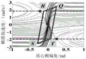
图4为β-r相平面示意图;Figure 4 is a schematic view of a β-r phase plane;
图5为试验测试中得到的横向轨迹误差。Figure 5 shows the lateral trajectory error obtained in the experimental test.
具体实施方式Detailed ways
下面结合附图并举实施例,对本发明进行详细描述。The present invention will be described in detail below with reference to the accompanying drawings and embodiments.
本发明提供了一种用于全轮独立转向及独立驱动无人车的最大包络线控制方法,将飞行控制技术中的包络线控制思想应用于无人车的路径跟踪控制中,提出了基于主动前轮转向(AFS)和直接横摆力矩控制(DYC)的无人车最大包络线控制框架,旨在控制无人车在行驶和操纵极限下沿预定路径行驶,提高无人车的机动性。The invention provides a maximum envelope control method for all-wheel independent steering and independent driving of an unmanned vehicle, and applies the envelope control idea in the flight control technology to the path tracking control of the unmanned vehicle. The maximum envelope control framework of unmanned vehicles based on active front steering (AFS) and direct yaw moment control (DYC) is designed to control unmanned vehicles to travel along a predetermined path under the driving and handling limits, and improve the performance of unmanned vehicles. flexibility.
图1所示为所提出的最大包络线控制器的总体结构,包括纵向、横向和横摆力矩控制器。纵向控制器的目的是根据G-G图的边界计算出的行驶极限以及期望路径来计算所需要的总牵引力或制动力。横向控制器的目的是通过对转向角的控制来减小实际路径和期望路径之间的误差。横摆力矩控制器基于预定义的车辆β-r相平面,根据车辆当前状态参数计算目标主动横摆力矩,并通过力分配控制器映射至各独立电机的转矩,保证无人车在极限行驶期间的操纵稳定性。Figure 1 shows the overall structure of the proposed maximum envelope controller, including longitudinal, lateral and yaw moment controllers. The purpose of the longitudinal controller is to calculate the required total traction or braking force based on the travel limits calculated from the boundaries of the G-G diagram and the desired path. The purpose of the lateral controller is to reduce the error between the actual path and the desired path by controlling the steering angle. The yaw moment controller is based on the predefined vehicle β-r phase plane, calculates the target active yaw moment according to the current state parameters of the vehicle, and maps it to the torque of each independent motor through the force distribution controller to ensure that the unmanned vehicle runs at the limit handling stability during the period.
本发明提出的控制方法所使用的包络线包括G-G图和β-r相平面。使用G-G图和β-r相平面分别用于描述行驶速度和车辆姿态的极限包络线。The envelope used by the control method proposed by the present invention includes a G-G diagram and a β-r phase plane. The G-G diagram and the β-r phase plane are used to describe the limit envelopes of the traveling speed and vehicle attitude, respectively.
图2所示G-G图示意图。G-G图是描述车辆极限速度特性的重要手段。G-G图由横向加速度和纵向加速度绘制,原点位于中间。G-G图的边界表示车辆的极限加速度,第一象限和第二象限的边界代表驶出弯道加速时的极限加速度(横向加速度和纵向加速度共同作用),第三象限和第四象限的边界代表驶入弯道制动时的极限加速度(横向加速度和纵向减速度共同作用),G-G图与X轴正半轴及负半轴的交点的物理意义为车辆的最大横向加速度,G-G图与Y轴正半轴的交点的物理意义为车辆的最大加速度,G-G图与Y轴负半轴的交点的物理意义为车辆的最大减速度。图2中圆圈代表轮胎摩擦圆极限,两条平行横线代表最大牵引力和制动力的极限。G-G图边界与平行横线、圆圈所形成的区域之间有较大的间隙,这是由于轮胎的垂直载荷转移等动力学特性造成的。因此,G-G图提供了对车辆极限的精确观测,可用于最大包络线控制方法中对无人车的精确控制,以实现无人车的极限行驶。Figure 2 shows a schematic diagram of the G-G diagram. G-G diagram is an important means to describe the vehicle's limit speed characteristics. The G-G diagram is drawn from lateral and longitudinal accelerations, with the origin in the middle. The boundary of the G-G diagram represents the limit acceleration of the vehicle, the boundaries of the first and second quadrants represent the limit acceleration when accelerating out of the curve (the lateral acceleration and the longitudinal acceleration work together), and the boundaries of the third and fourth quadrants represent driving The limit acceleration when braking into a curve (the lateral acceleration and longitudinal deceleration are combined), the physical meaning of the intersection of the G-G graph and the positive and negative semi-axes of the X-axis is the maximum lateral acceleration of the vehicle, and the G-G graph and the positive Y-axis are The physical meaning of the intersection of the half-axes is the maximum acceleration of the vehicle, and the physical meaning of the intersection of the G-G diagram and the negative half-axis of the Y-axis is the maximum deceleration of the vehicle. The circle in Figure 2 represents the circle limit of tire friction, and the two parallel horizontal lines represent the limit of maximum traction and braking force. There is a large gap between the G-G diagram boundary and the area formed by the parallel horizontal lines and circles, which is caused by the dynamic characteristics of the tire such as vertical load transfer. Therefore, the G-G diagram provides an accurate observation of the vehicle limit, which can be used for the precise control of the unmanned vehicle in the maximum envelope control method to realize the extreme driving of the unmanned vehicle.
图4为β-r相平面示意图。β-r相位图以无人车的横摆角速度和质心侧偏角作为变量,可确定无人车的安全姿态区域,清晰明确的表示无人车所能达到的姿态稳定极限。β-r相图的稳定姿态边界由平行四边形表示,图4β-r相平面中的
纵向控制器设计如下所述:纵向控制器主要依据G-G图设计,根据实际道路附着系数将由计算机仿真得到的G-G图边界调整为实际的G-G图边界。调整后的G-G图边界的最终描述为:The design of the longitudinal controller is as follows: the longitudinal controller is mainly designed according to the G-G diagram, and adjusts the G-G diagram boundary obtained by computer simulation to the actual G-G diagram boundary according to the actual road adhesion coefficient. The final description of the adjusted G-G graph boundary is:

式中:调节参数λ=μmax/μ0,其中μ0为试验台最大摩擦系数,μmax为最大路面附着系数,ax、ay分别为纵向和横向加速度,aymax为最大理想横向加速度,axmaxT、axmaxB分别为最大理想加速度和最大理想减速度。where μ 0 is the maximum friction coefficient of the test bench, μ max is the maximum road adhesion coefficient, a x and a yarethelongitudinaland lateral accelerations,respectively, and a ymaxis the maximum ideal lateral acceleration , axmaxT and axmaxB are the maximum ideal acceleration and the maximum ideal deceleration, respectively.
根据调整后的G-G图边界和期望路径的曲率,得出给定路径上的预设速度。根据预设速度可知期望速度和纵向加速度,进而根据牛顿第二定律计算得到前馈纵向力,设计前馈控制器;根据预设速度的期望车速与实际速度反馈的误差设计反馈控制器。将总纵向力分配到无人车的每个独立驱动电机上以调整转矩,从而实现无人车的纵向控制。图3为纵向控制器验证得到的G-G图,与目标G-G图基本吻合,这表明在纵向控制器的作用下,无人车实现了极限行驶,该纵向控制器实现了控制目标。Based on the adjusted G-G graph boundaries and the curvature of the desired path, a preset speed on a given path is derived. According to the preset speed, the expected speed and longitudinal acceleration can be known, and then the feedforward longitudinal force is calculated according to Newton's second law, and the feedforward controller is designed; the feedback controller is designed according to the error between the expected vehicle speed and the actual speed feedback at the preset speed. The total longitudinal force is distributed to each independent drive motor of the unmanned vehicle to adjust the torque, thereby realizing the longitudinal control of the unmanned vehicle. Figure 3 shows the G-G diagram obtained from the verification of the longitudinal controller, which is basically consistent with the target G-G diagram, which indicates that under the action of the longitudinal controller, the unmanned vehicle achieves the limit travel, and the longitudinal controller achieves the control target.
横向控制器设计如下所述:横向控制器对无人车的转向系统进行控制,从而消除无人车实际位置与给定路径的误差,横向控制器由前馈控制部分和反馈控制部分组成。The design of the lateral controller is as follows: the lateral controller controls the steering system of the unmanned vehicle, thereby eliminating the error between the actual position of the unmanned vehicle and the given path, and the lateral controller consists of a feedforward control part and a feedback control part.
前馈部分的转向角为:The steering angle of the feedforward part is:

式中:Ux为车速,r为横摆角速度,xp为控制器预瞄投影距离,β为质心侧偏角,κ为路径曲率,s为行驶距离,且:Where: Ux is the vehicle speed, r is the yaw rate, xp is the controller preview projection distance, β is the center of mass sideslip angle, κ is the path curvature, s is the travel distance, and:

式中:lf、lr分别为车辆质心位置到前轴和后轴的距离,cf、cr分别为车辆前后轮的轮胎侧偏刚度,Iz为转动惯量。where lf and lr are the distances from the center of mass of the vehicle to the front and rear axles, respectively, cf andcr are the tire cornering stiffnesses of the front and rear wheels of the vehicle, and Iz is the moment of inertia.
反馈部分为:The feedback section is:

式中:K2、K3为反馈增益,ep为控制器预瞄投影误差,ΔΦ为偏航角误差。In the formula: K2 and K3 are the feedback gains,ep is the controller preview projection error, and ΔΦ is the yaw angle error.
横向控制器的转向角的总值为δFFW+δFB。图5为横向控制器测试中的横向误差结果,其描述了车辆在给定路径跟踪控制试验过程中的位置与给定路径的误差,除了圆圈处的车辆失稳状态之外,可发现无人车的横向误差基本为零,说明横向控制器实现了其控制目标。在试验过程中所发生的失稳问题由下述横摆力矩控制器实现稳定性控制。The total value of the steering angle of the lateral controller is δFFW + δFB . Figure 5 is the lateral error result in the lateral controller test, which describes the error between the position of the vehicle and the given path during the given path tracking control test. Except for the unstable state of the vehicle at the circle, it can be found that no one The lateral error of the car is basically zero, indicating that the lateral controller has achieved its control goal. The instability problem that occurs during the test is controlled by the following yaw moment controller.
横摆力矩控制器设计如下所述:横摆力矩控制器旨在保证极限驾驶时的操纵稳定性。β-r相位图以无人车的横摆角速度和质心侧偏角作为变量,可精确的确定无人车的安全姿态区域,清晰明确的表示无人车所能达到的稳定姿态极限,β-r相图的安全边界由平行四边形表示。当传感器检测到车辆状态超出安全边界时,横摆力矩控制器生成主动横摆力矩,对无人车进行控制,以防止车辆失去稳定性。确定安全包络后,采用滑模控制器产生主动横摆力矩:The yaw moment controller is designed as follows: The yaw moment controller is designed to ensure handling stability during extreme driving. The β-r phase diagram uses the yaw rate and the side-slip angle of the unmanned vehicle as variables, which can accurately determine the safe attitude area of the unmanned vehicle, and clearly and clearly represent the stable attitude limit that the unmanned vehicle can achieve. β- The safe frontier of the r-phase diagram is represented by a parallelogram. When the sensor detects that the vehicle state exceeds the safety boundary, the yaw moment controller generates an active yaw moment to control the unmanned vehicle to prevent the vehicle from losing its stability. After the safety envelope is determined, a sliding mode controller is used to generate the active yaw moment:
M=Meq-(Kssat(S/φ)+KpS) (5)M=Meq -(Ks sat(S/φ)+Kp S) (5)
式中Meq为等效控制横摆力矩:where Meq is the equivalent control yaw moment:

式中:sat为饱和函数,Φ为滑模控制中边界层厚度,S为滑动面,rsafe,βsafe分别为车辆在稳定姿态下的横摆角速度和质心侧偏角,Ks、Kp分别为控制参数,δ为转向轮转角。where: sat is the saturation function, Φ is the thickness of the boundary layer in the sliding mode control, S is the sliding surface, rsafe , βsafe are the yaw rate and the center of mass sideslip angle of the vehicle in a stable attitude, Ks , Kp are the control parameters, respectively, and δ is the steering wheel angle.
将所需的主动横摆力矩分配给各个独立的电机,实现对无人车的横摆力矩控制,根据图5所示横向误差在失稳后迅速降为零,说明横摆力矩控制器成功保证了无人车的稳定性Allocate the required active yaw moment to each independent motor to realize the yaw moment control of the unmanned vehicle. According to the lateral error shown in Figure 5, the lateral error quickly drops to zero after instability, indicating that the yaw moment controller successfully guarantees the stability of the unmanned vehicle
综上所述,以上仅为本发明的较佳实施例而已,并非用于限定本发明的保护范围。凡在本发明的精神和原则之内,所作的任何修改、等同替换、改进等,均应包含在本发明的保护范围之内。To sum up, the above are only preferred embodiments of the present invention, and are not intended to limit the protection scope of the present invention. Any modification, equivalent replacement, improvement, etc. made within the spirit and principle of the present invention shall be included within the protection scope of the present invention.
Claims (1)
Translated fromChinese


Priority Applications (1)
| Application Number | Priority Date | Filing Date | Title |
|---|---|---|---|
| CN202010249871.2ACN111572558A (en) | 2020-04-01 | 2020-04-01 | A Dynamic Control Method for Maximum Envelope of Unmanned Vehicles |
Applications Claiming Priority (1)
| Application Number | Priority Date | Filing Date | Title |
|---|---|---|---|
| CN202010249871.2ACN111572558A (en) | 2020-04-01 | 2020-04-01 | A Dynamic Control Method for Maximum Envelope of Unmanned Vehicles |
Publications (1)
| Publication Number | Publication Date |
|---|---|
| CN111572558Atrue CN111572558A (en) | 2020-08-25 |
Family
ID=72089732
Family Applications (1)
| Application Number | Title | Priority Date | Filing Date |
|---|---|---|---|
| CN202010249871.2APendingCN111572558A (en) | 2020-04-01 | 2020-04-01 | A Dynamic Control Method for Maximum Envelope of Unmanned Vehicles |
Country Status (1)
| Country | Link |
|---|---|
| CN (1) | CN111572558A (en) |
Cited By (9)
| Publication number | Priority date | Publication date | Assignee | Title |
|---|---|---|---|---|
| CN112068432A (en)* | 2020-09-07 | 2020-12-11 | 北京理工大学 | Method and device for controlling pole allocation of unmanned vehicle dynamics system |
| CN112269385A (en)* | 2020-10-23 | 2021-01-26 | 北京理工大学 | Cloud unmanned vehicle dynamics control system and method |
| CN112706756A (en)* | 2020-11-25 | 2021-04-27 | 东风越野车有限公司 | Yaw stability control method for off-road vehicle driven by hub motor |
| CN113050650A (en)* | 2021-03-24 | 2021-06-29 | 苏州泛像汽车技术有限公司 | Unmanned vehicle path tracking control method and system based on output feedback |
| CN113401113A (en)* | 2021-06-25 | 2021-09-17 | 江苏大学 | Unmanned vehicle direct yaw moment control method and controller based on vehicle stable envelope line |
| CN114633736A (en)* | 2022-02-25 | 2022-06-17 | 清华大学深圳国际研究生院 | Method and device for determining limit bending speed of vehicle stable over bending |
| CN114734986A (en)* | 2022-04-20 | 2022-07-12 | 江苏理工学院 | Distributed driving electric vehicle stability control system and method based on phase plane |
| CN115158445A (en)* | 2022-07-11 | 2022-10-11 | 岚图汽车科技有限公司 | A vehicle steering redundancy control method, system, electronic device and storage medium |
| CN119099653A (en)* | 2024-09-05 | 2024-12-10 | 长沙理工大学 | A method and device for collaborative planning of path and speed of an autonomous driving vehicle |
Citations (3)
| Publication number | Priority date | Publication date | Assignee | Title |
|---|---|---|---|---|
| WO2007031567A1 (en)* | 2005-09-14 | 2007-03-22 | Continental Teves Ag & Co. Ohg | Method for determining an inhomogeneous roadway |
| CN105539426A (en)* | 2016-01-05 | 2016-05-04 | 北京理工大学 | Dynamic stability control system for multiaxial distributed electromechanical driving vehicle |
| CN106926840A (en)* | 2017-03-13 | 2017-07-07 | 北京理工大学 | A kind of vehicle extremal dynamic model Trajectory Tracking Control System |
- 2020
- 2020-04-01CNCN202010249871.2Apatent/CN111572558A/enactivePending
Patent Citations (3)
| Publication number | Priority date | Publication date | Assignee | Title |
|---|---|---|---|---|
| WO2007031567A1 (en)* | 2005-09-14 | 2007-03-22 | Continental Teves Ag & Co. Ohg | Method for determining an inhomogeneous roadway |
| CN105539426A (en)* | 2016-01-05 | 2016-05-04 | 北京理工大学 | Dynamic stability control system for multiaxial distributed electromechanical driving vehicle |
| CN106926840A (en)* | 2017-03-13 | 2017-07-07 | 北京理工大学 | A kind of vehicle extremal dynamic model Trajectory Tracking Control System |
Non-Patent Citations (7)
| Title |
|---|
| JUN NI: "Envelope Control for Four-Wheel Independently Actuated Autonomous Ground Vehicle Through AFS/DYC Integrated Control", 《IEEE TRANSACTIONS ON VEHICULAR TECHNOLOGY》* |
| KRISADA KRITAYAKIRANA ET AL: "Autonomous Cornering at the Limits:", 《6TH IFAC SYMPOSIUM ADVANCES IN AUTOMOTIVE CONTROL》* |
| KRISADA KRITAYAKIRANA ET AL: "Autonomous vehicle control at the limits", 《INT. J. VEHICLE AUTONOMOUS SYSTEMS》* |
| KRISADA KRITAYAKIRANA ET AL: "Using the centre of percussion to design", 《VEHICLE SYSTEM DYNAMICS: INTERNATIONAL JOURNAL OF VEHICLE MECHANICS AND MOBILITY》* |
| MIAOMIAO FU ET AL: "PATH TRACKING FOR AUTONOMOUS RACE CAR", 《INTERNATIONAL JOURNAL OF AUTOMOTIVE TECHNOLOGY》* |
| 付苗苗: "高速无人车辆极限包络特性与轨迹跟踪方法研究", 《中国优秀硕士学位论文全文数据库工程科技Ⅱ辑》* |
| 邓召文等: "基于特定赛道的FSAE赛车操纵稳定性仿真分析", 《拖拉机与农用运输车》* |
Cited By (12)
| Publication number | Priority date | Publication date | Assignee | Title |
|---|---|---|---|---|
| CN112068432A (en)* | 2020-09-07 | 2020-12-11 | 北京理工大学 | Method and device for controlling pole allocation of unmanned vehicle dynamics system |
| CN112269385A (en)* | 2020-10-23 | 2021-01-26 | 北京理工大学 | Cloud unmanned vehicle dynamics control system and method |
| CN112706756A (en)* | 2020-11-25 | 2021-04-27 | 东风越野车有限公司 | Yaw stability control method for off-road vehicle driven by hub motor |
| CN112706756B (en)* | 2020-11-25 | 2022-03-29 | 东风越野车有限公司 | Yaw stability control method for off-road vehicle driven by hub motor |
| CN113050650A (en)* | 2021-03-24 | 2021-06-29 | 苏州泛像汽车技术有限公司 | Unmanned vehicle path tracking control method and system based on output feedback |
| CN113401113A (en)* | 2021-06-25 | 2021-09-17 | 江苏大学 | Unmanned vehicle direct yaw moment control method and controller based on vehicle stable envelope line |
| CN113401113B (en)* | 2021-06-25 | 2024-06-07 | 江苏大学 | Unmanned vehicle direct yaw moment control method and controller based on vehicle stability envelope |
| CN114633736A (en)* | 2022-02-25 | 2022-06-17 | 清华大学深圳国际研究生院 | Method and device for determining limit bending speed of vehicle stable over bending |
| CN114734986A (en)* | 2022-04-20 | 2022-07-12 | 江苏理工学院 | Distributed driving electric vehicle stability control system and method based on phase plane |
| CN115158445A (en)* | 2022-07-11 | 2022-10-11 | 岚图汽车科技有限公司 | A vehicle steering redundancy control method, system, electronic device and storage medium |
| CN115158445B (en)* | 2022-07-11 | 2023-06-23 | 岚图汽车科技有限公司 | A vehicle steering redundancy control method, system, electronic equipment and storage medium |
| CN119099653A (en)* | 2024-09-05 | 2024-12-10 | 长沙理工大学 | A method and device for collaborative planning of path and speed of an autonomous driving vehicle |
Similar Documents
| Publication | Publication Date | Title |
|---|---|---|
| CN111572558A (en) | A Dynamic Control Method for Maximum Envelope of Unmanned Vehicles | |
| CN102163059B (en) | Attitude control system and attitude control method of variable thrust unmanned aerial vehicle | |
| CN104443022B (en) | A kind of four motorized wheels electric car stability control method and system | |
| Velenis et al. | Steady-state cornering equilibria and stabilisation for a vehicle during extreme operating conditions | |
| CN110395120A (en) | A kind of weaving control method of four-wheel distribution driving car | |
| CN107215329B (en) | A distributed drive electric vehicle lateral stability control method based on ATSM | |
| CN111923908A (en) | Stability-fused intelligent automobile path tracking control method | |
| CN105253141A (en) | Wheel longitudinal force regulation-based vehicle handling stability control method | |
| CN110481343A (en) | The combination Second Order Sliding Mode Control method of four-wheel In-wheel motor driving automobile torque compensation | |
| Kim et al. | Drive control algorithm for an independent 8 in-wheel motor drive vehicle | |
| CN111086400B (en) | Method and system for direct force dynamics control of all-wheel independent steering and independent drive unmanned vehicles | |
| CN110588633A (en) | A path tracking and stability control method for intelligent vehicles under extreme conditions | |
| CN108327702A (en) | A kind of four-wheel wheel hub motor independence drive control method | |
| CN115431790A (en) | Cooperative control method of AFS and DYC for 8-wheel distributed electric drive vehicle | |
| Li et al. | Adaptive sliding mode control of lateral stability of four wheel hub electric vehicles | |
| Yihu et al. | A fuzzy control method to improve vehicle yaw stability based on integrated yaw moment control and active front steering | |
| CN114987226B (en) | A hierarchical fault-tolerant control method for a four-wheel independent electric drive port AGV | |
| Ni et al. | Path following control for autonomous formula racecar: Autonomous formula student competition | |
| CN119176122B (en) | A reconfigurable distributed drive multi-axis vehicle trajectory tracking method and carrier device | |
| CN113479184B (en) | Longitudinal and transverse cooperative control method for mechanical elastic electric wheel vehicle | |
| Li et al. | Longitudinal and lateral control for four wheel steering vehicles | |
| Sun et al. | Design of four wheel steering and direct yaw moment control for unmanned vehicle with path tracking controller in extreme maneuvers | |
| CN117962866A (en) | Vehicle motion control method for longitudinal and transverse sagging cooperative control | |
| CN113147736A (en) | Electric vehicle stability control method based on independent gear train | |
| Park | Sideslip angle control of electronic-four-wheel drive vehicle using backstepping controller |
Legal Events
| Date | Code | Title | Description |
|---|---|---|---|
| PB01 | Publication | ||
| PB01 | Publication | ||
| SE01 | Entry into force of request for substantive examination | ||
| SE01 | Entry into force of request for substantive examination | ||
| WD01 | Invention patent application deemed withdrawn after publication | Application publication date:20200825 | |
| WD01 | Invention patent application deemed withdrawn after publication |