CN111568449A - Joint soft tissue balance measurement device - Google Patents
Joint soft tissue balance measurement deviceDownload PDFInfo
- Publication number
- CN111568449A CN111568449ACN202010491605.0ACN202010491605ACN111568449ACN 111568449 ACN111568449 ACN 111568449ACN 202010491605 ACN202010491605 ACN 202010491605ACN 111568449 ACN111568449 ACN 111568449A
- Authority
- CN
- China
- Prior art keywords
- abutting
- base body
- soft tissue
- groove
- rack portion
- Prior art date
- Legal status (The legal status is an assumption and is not a legal conclusion. Google has not performed a legal analysis and makes no representation as to the accuracy of the status listed.)
- Granted
Links
Images


Classifications
- A—HUMAN NECESSITIES
- A61—MEDICAL OR VETERINARY SCIENCE; HYGIENE
- A61B—DIAGNOSIS; SURGERY; IDENTIFICATION
- A61B5/00—Measuring for diagnostic purposes; Identification of persons
- A61B5/22—Ergometry; Measuring muscular strength or the force of a muscular blow
- A61B5/224—Measuring muscular strength
- A—HUMAN NECESSITIES
- A61—MEDICAL OR VETERINARY SCIENCE; HYGIENE
- A61F—FILTERS IMPLANTABLE INTO BLOOD VESSELS; PROSTHESES; DEVICES PROVIDING PATENCY TO, OR PREVENTING COLLAPSING OF, TUBULAR STRUCTURES OF THE BODY, e.g. STENTS; ORTHOPAEDIC, NURSING OR CONTRACEPTIVE DEVICES; FOMENTATION; TREATMENT OR PROTECTION OF EYES OR EARS; BANDAGES, DRESSINGS OR ABSORBENT PADS; FIRST-AID KITS
- A61F2/00—Filters implantable into blood vessels; Prostheses, i.e. artificial substitutes or replacements for parts of the body; Appliances for connecting them with the body; Devices providing patency to, or preventing collapsing of, tubular structures of the body, e.g. stents
- A61F2/02—Prostheses implantable into the body
- A61F2/30—Joints
- A61F2/46—Special tools for implanting artificial joints
- A61F2/4657—Measuring instruments used for implanting artificial joints
- A61F2002/4666—Measuring instruments used for implanting artificial joints for measuring force, pressure or mechanical tension
Landscapes
- Health & Medical Sciences (AREA)
- Life Sciences & Earth Sciences (AREA)
- Animal Behavior & Ethology (AREA)
- General Health & Medical Sciences (AREA)
- Biophysics (AREA)
- Transplantation (AREA)
- Engineering & Computer Science (AREA)
- Biomedical Technology (AREA)
- Heart & Thoracic Surgery (AREA)
- Orthopedic Medicine & Surgery (AREA)
- Veterinary Medicine (AREA)
- Public Health (AREA)
- Surgery (AREA)
- Physical Education & Sports Medicine (AREA)
- Physics & Mathematics (AREA)
- Molecular Biology (AREA)
- Nuclear Medicine, Radiotherapy & Molecular Imaging (AREA)
- Medical Informatics (AREA)
- Pathology (AREA)
- Cardiology (AREA)
- Oral & Maxillofacial Surgery (AREA)
- Vascular Medicine (AREA)
- Measurement Of The Respiration, Hearing Ability, Form, And Blood Characteristics Of Living Organisms (AREA)
- Dental Prosthetics (AREA)
Abstract
Description
Translated fromChinese技术领域technical field
本发明涉及骨科用医疗器械领域,具体而言,涉及一种关节软组织平衡测量装置。The invention relates to the field of orthopedic medical instruments, in particular to a joint soft tissue balance measuring device.
背景技术Background technique
膝关节主要由股骨、胫骨和髌骨构成,关节囊附着于各骨关节软骨的周缘,关节囊的周围有韧带加固,由膝关节处的关节囊、韧带、肌肉、肌腱、神经、血管等构成膝关节软组织。The knee joint is mainly composed of the femur, tibia and patella. The joint capsule is attached to the periphery of the articular cartilage of each bone. The joint capsule is reinforced by ligaments. The joint capsule, ligaments, muscles, tendons, nerves and blood vessels at the knee joint constitute the knee joint. Joint soft tissue.
随着老龄化社会的到来,膝关节病变已经成为影响老年人生活质量的一种常见疾病。全膝关节置换术是治疗晚期膝关节病变的一种有效方法。全膝关节置换是指用人工假体取代已经受到严重损坏而不能行使正常功能的膝关节,从而消除膝关节的疼痛,恢复其稳定性和活动度。With the advent of an aging society, knee joint disease has become a common disease affecting the quality of life of the elderly. Total knee arthroplasty is an effective method for the treatment of advanced knee joint disease. Total knee replacement is the replacement of a knee joint that has been severely damaged and unable to function normally with an artificial prosthesis, thereby eliminating pain in the knee joint and restoring its stability and range of motion.
在全膝关节置换术中,为了安装人工假体,需要对股骨和胫骨进行截切,以使截切后的骨轮廓能与人工假体的安装面相匹配。例如,对于胫骨而言,截切步骤主要包括胫骨近端(指靠近心脏的一端)的截切;对于股骨而言,截切步骤主要包括股骨远端(指远离心脏的一端)的截切,以及股骨前髁、后髁、斜面及髁间的截骨。当完成股骨及胫骨远端骨质切割后,股骨与胫骨之间形成截骨间隙,整个置换术将进入到一个非常关键的步骤,即膝周软组织平衡。为了获得更好的远期随访效果,软组织平衡的精确性是人们不断探索和追求的目标。相关技术中的全膝关节置换术通过机械导向装置进行髓内、髓外定位截骨,而后医生凭借肉眼、手感和经验来定位解剖标志、下肢力线和假体旋转轴线,然后手工划线截骨、人工假体放置和软组织平衡。虽然人们不断完善切割骨组织的手术器械的机械定位功能,提高人工假体植入至截切间隙的准确性,但相对于切割骨组织而言,软组织平衡没有很好的配套器械可以帮助医生定位、测量和校正,软组织平衡通常依赖医生的经验和技术,对软组织进行测力的准确度较差,处理是否得当,直接影响术后关节功能和稳定性。In total knee arthroplasty, in order to install the prosthesis, the femur and tibia need to be cut so that the contour of the cut bone can match the installation surface of the artificial prosthesis. For example, for the tibia, the cutting step mainly includes the cutting of the proximal end of the tibia (referring to the end close to the heart); for the femur, the cutting step mainly includes the cutting of the distal end of the femur (referring to the end away from the heart), As well as osteotomy of the anterior, posterior, oblique and intercondylar femoral condyles. When the bone cutting of the femur and the distal tibia is completed, an osteotomy space is formed between the femur and the tibia, and the whole replacement operation will enter a very critical step, that is, the balance of the soft tissue around the knee. In order to obtain better long-term follow-up effect, the accuracy of soft tissue balance is the goal of continuous exploration and pursuit. The total knee arthroplasty in the related art performs intramedullary and extramedullary positioning osteotomies through a mechanical guide device, and then the doctor locates the anatomical landmarks, lower limb force lines and prosthesis rotation axis with the naked eye, hand feeling and experience, and then manually scribes the cut. Bone, prosthesis placement and soft tissue balancing. Although people continue to improve the mechanical positioning function of surgical instruments for cutting bone tissue and improve the accuracy of artificial prosthesis implantation to the cutting gap, compared with cutting bone tissue, there is no good supporting instrument for soft tissue balance that can help doctors position , measurement and correction, soft tissue balance usually depends on the doctor's experience and technology, the accuracy of soft tissue force measurement is poor, and whether it is handled properly will directly affect the postoperative joint function and stability.
发明内容SUMMARY OF THE INVENTION
本发明的主要目的在于提供一种关节软组织平衡测量装置,以解决相关技术中对软组织进行测力的准确度较差的问题。The main purpose of the present invention is to provide a joint soft tissue balance measurement device, so as to solve the problem of poor accuracy of force measurement on soft tissue in the related art.
为了实现上述目的,本发明提供了一种关节软组织平衡测量装置,包括:基体;抵顶件,可移动地设置在基体上,抵顶件的侧壁上设置有刻度线;传动结构,设置在基体和抵顶件之间;扭力螺丝刀,与传动结构连接并通过传动结构驱动抵顶件上下移动,扭力螺丝刀包括指示盘及指示针,指示盘上设置有标定抵顶件受力值的刻度。In order to achieve the above purpose, the present invention provides a joint soft tissue balance measurement device, which includes: a base body; an abutting member, which is movably arranged on the base body, and a scale line is provided on the side wall of the abutting member; Between the base body and the abutment piece; the torque screwdriver is connected with the transmission structure and drives the abutment piece to move up and down through the transmission structure. The torque screwdriver includes an indicator disc and an indicator needle, and the indicator disc is provided with a scale for calibrating the force value of the abutment piece.
进一步地,传动结构包括齿轮部、第一齿条部和第二齿条部,齿轮部与第一齿条部和第二齿条部相啮合,齿轮部可移动地设置在第一齿条部和第二齿条部之间,第一齿条部设置在基体上,第二齿条部设置在抵顶件上,齿轮部与扭力螺丝刀连接。Further, the transmission structure includes a gear portion, a first rack portion and a second rack portion, the gear portion is engaged with the first rack portion and the second rack portion, and the gear portion is movably arranged on the first rack portion and the second rack portion, the first rack portion is arranged on the base body, the second rack portion is arranged on the abutting member, and the gear portion is connected with the torque screwdriver.
进一步地,扭力螺丝刀包括指示盘及指示针,指示盘上设置有标定抵顶件受力值的刻度。Further, the torque screwdriver includes an indicator plate and an indicator needle, and the indicator plate is provided with a scale for calibrating the force value of the abutting member.
进一步地,基体包括底板及设置在底板上的第一凸出部,抵顶件包括抵顶块和设置在抵顶块上的凹槽,第一凸出部位于凹槽内,齿轮部位于第一凸出部的侧壁和凹槽的槽壁之间,第一齿条部设置在第一凸出部朝向齿轮部的侧壁上,第二齿条部设置在凹槽朝向齿轮部的槽壁上。Further, the base body includes a bottom plate and a first protruding portion arranged on the bottom plate, the abutting member includes an abutting block and a groove arranged on the abutting block, the first protruding portion is located in the groove, and the gear portion is located in the first protruding portion. Between the side wall of the protruding portion and the groove wall of the groove, the first rack portion is provided on the side wall of the first protruding portion facing the gear portion, and the second rack portion is provided on the groove of the groove facing the gear portion on the wall.
进一步地,基体包括底板及设置在底板上的围板,抵顶件位于围板的内部,传动结构位于底板和抵顶件之间。Further, the base body includes a bottom plate and a surrounding plate arranged on the bottom plate, the abutting member is located inside the surrounding plate, and the transmission structure is located between the bottom plate and the abutting member.
进一步地,围板的内壁上设置有第一导向平面,抵顶件的外壁上设置有与第一导向平面接触配合的第二导向平面。Further, the inner wall of the enclosure plate is provided with a first guide plane, and the outer wall of the abutting member is provided with a second guide plane which is in contact with the first guide plane.
进一步地,抵顶件包括抵顶块和设置在抵顶块的底部上的第二凸出部,第二齿条部的一部分位于第二凸出部上,基体上设置有能够避让第二凸出部的避让部。Further, the abutting member includes an abutting block and a second protruding portion arranged on the bottom of the abutting block, a part of the second rack portion is located on the second protruding portion, and the base body is provided with a second protruding portion that can avoid the second protruding portion. Out of the escape department.
进一步地,关节软组织平衡测量装置还包括防脱结构,防脱结构设置在基体和抵顶件之间,防脱结构包括止挡件和与止挡件配合的止挡槽,止挡件设置基体上,止挡槽设置在抵顶件上。Further, the joint soft tissue balance measurement device also includes an anti-drop structure, the anti-drop structure is arranged between the base body and the abutting member, the anti-drop structure includes a stopper and a stopper groove matched with the stopper, and the stopper is provided with the base body. , the stop groove is arranged on the abutting member.
进一步地,抵顶件的侧壁上设置有刻度线。Further, a scale line is provided on the side wall of the abutting member.
进一步地,关节软组织平衡测量装置还包括握持件,握持件连接在基体上。Further, the joint soft tissue balance measurement device further includes a holding member, and the holding member is connected to the base body.
进一步地,凹槽贯穿抵顶块的相对设置的两个侧面。Further, the groove runs through two opposite sides of the abutting block.
应用本发明的技术方案,关节软组织平衡测量装置包括:基体、抵顶件和传动结构。抵顶件可移动地设置在基体上,抵顶件的侧壁上设置有刻度线。传动结构设置在基体和抵顶件之间。扭力螺丝刀与传动结构连接并通过传动结构驱动抵顶件上下移动,扭力螺丝刀包括指示盘及指示针,指示盘上设置有标定抵顶件受力值的刻度。在膝关节置换术中,当完成股骨及胫骨远端骨质切割后,将关节软组织平衡测量装置植入股骨与胫骨之间的截骨间隙中,旋转扭力螺丝刀,扭力螺丝刀驱动传动结构转动。在传动结构的作用下,抵顶件上移,直至充满截骨间隙,以使抵顶件与股骨髁截骨面接触配合,此时扭力螺丝刀的指示盘上的数值为零;当继续旋转扭力螺丝刀,抵顶件将向股骨髁截骨面施加抵顶力,抵顶件首先克服关节的重力而后逐步上移并拉升韧带,直至韧带及周围软组织拉紧,如果抵顶件继续加力,扭力螺丝刀的指示针的指示数值也逐渐上升,抵顶力将反应韧带及周围软组织的牵张力,牵张力和抵顶力是一对作用力反作用力,两值相等。在这个过程中,根据抵顶件的侧壁上的刻度线,可知抵顶件上移的距离,此时观察指示针在指示盘上的指示数值,该指示数值为软组织的牵张力。当获得内侧副韧带和外侧副韧带两个区域的软组织的牵张力之后,根据两个区域的牵张力以及抵顶件上移的距离能够直观地、准确地判断是否需要对膝关节软组织的松解度进行调节。需要时,则平衡膝关节软组织的松解度。因此本申请的技术方案有效地解决了相关技术中对软组织进行测力的准确度较差的问题。Applying the technical solution of the present invention, the joint soft tissue balance measurement device includes: a base body, an abutting member and a transmission structure. The abutting piece is movably arranged on the base body, and a scale line is arranged on the side wall of the abutting piece. The transmission structure is arranged between the base body and the abutting member. The torque screwdriver is connected with the transmission structure and drives the abutment member to move up and down through the transmission structure. The torque screwdriver includes an indicator plate and an indicator needle, and the indicator plate is provided with a scale for calibrating the force value of the abutment member. In knee arthroplasty, after completing the bone cutting of the femur and the distal end of the tibia, the articular soft tissue balance measurement device is implanted into the osteotomy gap between the femur and the tibia, and the torque screwdriver is rotated, and the torque screwdriver drives the transmission structure to rotate. Under the action of the transmission structure, the abutment piece moves up until the osteotomy gap is filled, so that the abutment piece is in contact with the osteotomy surface of the femoral condyle. At this time, the value on the indicator plate of the torque screwdriver is zero; Screwdriver, the abutment piece will exert an abutment force on the osteotomy surface of the femoral condyle. The abutment piece will first overcome the gravity of the joint and then gradually move up and pull up the ligament until the ligament and surrounding soft tissue are taut. If the abutment piece continues to add force, The indication value of the indicator needle of the torque screwdriver also gradually increases, and the contact force will reflect the pulling force of the ligament and surrounding soft tissues. In this process, according to the scale line on the side wall of the abutment piece, the distance that the abutment piece moves upward can be known. At this time, observe the indicated value of the indicator needle on the indicator disc, which is the tensile force of the soft tissue. After obtaining the soft tissue stretches of the medial collateral ligament and lateral collateral ligament regions, it is possible to intuitively and accurately determine whether the soft tissue of the knee joint needs to be released according to the stretches of the two regions and the distance that the abutment member moves upward. adjust the degree. When needed, the release of the soft tissue of the knee joint is balanced. Therefore, the technical solution of the present application effectively solves the problem of poor force measurement accuracy of soft tissue in the related art.
附图说明Description of drawings
构成本申请的一部分的说明书附图用来提供对本发明的进一步理解,本发明的示意性实施例及其说明用于解释本发明,并不构成对本发明的不当限定。在附图中:The accompanying drawings forming a part of the present application are used to provide further understanding of the present invention, and the exemplary embodiments of the present invention and their descriptions are used to explain the present invention and do not constitute an improper limitation of the present invention. In the attached image:
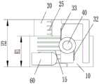
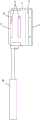
图1示出了根据本发明的关节软组织平衡测量装置的实施例的抵顶件伸出基体时的第一视角的立体结构示意图;Fig. 1 shows a schematic three-dimensional structure diagram of a first viewing angle when the abutment member of the embodiment of the joint soft tissue balance measurement device according to the present invention protrudes from the base body;
图2示出了图1的关节软组织平衡测量装置的抵顶件伸出基体时的主视示意图;Fig. 2 shows the schematic front view of the joint soft tissue balance measuring device of Fig. 1 when the abutting member extends out of the base;
图3示出了图1的关节软组织平衡测量装置的抵顶件伸出基体时的剖视示意图;Fig. 3 shows a schematic cross-sectional view when the abutment member of the joint soft tissue balance measuring device of Fig. 1 protrudes from the base;
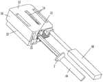
图4示出了图1的关节软组织平衡测量装置的抵顶件伸出基体时的第二视角的立体结构示意图;FIG. 4 shows a schematic three-dimensional structure diagram of the second viewing angle when the abutment member of the joint soft tissue balance measurement device of FIG. 1 extends out of the base body;
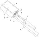
图5示出了图1的关节软组织平衡测量装置的抵顶件伸出基体时的第三视角的立体结构示意图;Fig. 5 shows the three-dimensional structural schematic diagram of the third viewing angle when the abutting member of the joint soft tissue balance measuring device of Fig. 1 extends out of the base;
图6示出了图1的关节软组织平衡测量装置的抵顶件未伸出基体时的第一视角的立体结构示意图;FIG. 6 is a schematic three-dimensional structural diagram of the first viewing angle when the abutting member of the joint soft tissue balance measuring device of FIG. 1 does not extend out of the base body;
图7示出了图1的关节软组织平衡测量装置的抵顶件未伸出基体时的主视示意图;Fig. 7 shows a schematic front view of the joint soft tissue balance measuring device of Fig. 1 when the abutting member does not protrude from the base;
图8示出了图1的关节软组织平衡测量装置的抵顶件未伸出基体时的剖视示意图;Fig. 8 shows a schematic cross-sectional view of the joint soft tissue balance measuring device of Fig. 1 when the abutment member does not protrude from the base;
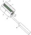
图9示出了图1的关节软组织平衡测量装置的抵顶件未伸出基体时的第二视角的立体结构示意图;FIG. 9 shows a schematic three-dimensional structure diagram of the second viewing angle when the abutment member of the joint soft tissue balance measurement device of FIG. 1 does not extend out of the base body;
图10示出了图1的关节软组织平衡测量装置的抵顶件未伸出基体时的第三视角的立体结构示意图;Fig. 10 shows a three-dimensional structural schematic diagram of the third viewing angle when the abutting member of the joint soft tissue balance measuring device of Fig. 1 does not extend out of the base;
图11示出了图1的关节软组织平衡测量装置的基体的第一视角的立体结构示意图;FIG. 11 is a schematic three-dimensional structural diagram of the base body of the joint soft tissue balance measurement device of FIG. 1 from a first perspective;
图12示出了图11的关节软组织平衡测量装置的基体的主视示意图;Fig. 12 shows a schematic front view of the base body of the joint soft tissue balance measurement device of Fig. 11;
图13示出了图11的关节软组织平衡测量装置的基体的俯视示意图;Fig. 13 shows a schematic top view of the base body of the joint soft tissue balance measurement device of Fig. 11;
图14示出了图1的关节软组织平衡测量装置的基体的第二视角的立体结构示意图;Fig. 14 shows a schematic three-dimensional structural diagram of the base body of the joint soft tissue balance measurement device of Fig. 1 from a second perspective;
图15示出了图1的关节软组织平衡测量装置的基体的第三视角的立体结构示意图;FIG. 15 is a schematic three-dimensional structural diagram of the base body of the joint soft tissue balance measurement device of FIG. 1 from a third angle of view;
图16示出了图1的关节软组织平衡测量装置的抵顶件的第一视角的立体结构示意图;FIG. 16 is a schematic three-dimensional structural diagram of the abutment member of the joint soft tissue balance measurement device of FIG. 1 from a first perspective;
图17示出了图16的关节软组织平衡测量装置的抵顶件的主视示意图;Fig. 17 shows a schematic front view of the abutment member of the joint soft tissue balance measurement device of Fig. 16;
图18示出了图1的关节软组织平衡测量装置的抵顶件的第二视角的立体结构示意图;Fig. 18 is a schematic three-dimensional structural diagram of the abutment member of the joint soft tissue balance measurement device of Fig. 1 from a second perspective;
图19示出了图1的关节软组织平衡测量装置的抵顶件的第三视角的立体结构示意图;Fig. 19 shows a three-dimensional schematic view of the abutment member of the joint soft tissue balance measurement device of Fig. 1 from a third perspective;
图20示出了图1的关节软组织平衡测量装置的齿轮部和扭力螺丝刀连接时的立体结构示意图;Fig. 20 shows a schematic three-dimensional structure diagram of the joint soft tissue balance measurement device of Fig. 1 when the gear portion and the torque screwdriver are connected;
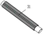
图21示出了图1的关节软组织平衡测量装置的齿轮部的立体结构示意图;Fig. 21 shows a schematic three-dimensional structure diagram of the gear portion of the joint soft tissue balance measurement device of Fig. 1;
图22示出了图1的关节软组织平衡测量装置的扭力螺丝刀的立体结构示意图;Fig. 22 shows a three-dimensional schematic diagram of the torque screwdriver of the joint soft tissue balance measurement device of Fig. 1;
图23示出了图1的关节软组织平衡测量装置的扭力螺丝刀的扭矩值和压力值的关系曲线图;以及FIG. 23 is a graph showing the relationship between the torque value and the pressure value of the torque screwdriver of the joint soft tissue balance measurement device of FIG. 1; and
图24示出了图1的关节软组织平衡测量装置的扭力螺丝刀的结构示意图。FIG. 24 shows a schematic structural diagram of the torque screwdriver of the joint soft tissue balance measurement device of FIG. 1 .
其中,上述附图包括以下附图标记:Wherein, the above-mentioned drawings include the following reference signs:
1、手柄;2、指示盘;3、指示针;6、套筒杆;10、基体;11、第一导向平面;12、底板;13、第一凸出部;14、避让部;15、刻线;16、围板;20、抵顶件;21、第二导向平面;22、抵顶块;23、凹槽;24、第二凸出部;25、刻度线;30、传动结构;31、齿轮部;32、第一齿条部;33、第二齿条部;40、扭力螺丝刀;50、防脱结构;51、止挡件;52、止挡槽;60、握持件。1, handle; 2, indicator plate; 3, indicator needle; 6, sleeve rod; 10, base body; 11, first guide plane; 12, bottom plate; 13, first protruding part; 14, avoidance part; 15, engraved line; 16, enclosure plate; 20, abutment piece; 21, second guide plane; 22, abutment block; 23, groove; 24, second protrusion; 25, scale line; 30, transmission structure; 31, gear part; 32, first rack part; 33, second rack part; 40, torque screwdriver; 50, anti-dropping structure; 51, stopper; 52, stopper groove;
具体实施方式Detailed ways
下面将结合本发明实施例中的附图,对本发明实施例中的技术方案进行清楚、完整地描述,显然,所描述的实施例仅仅是本发明一部分实施例,而不是全部的实施例。以下对至少一个示例性实施例的描述实际上仅仅是说明性的,决不作为对本发明及其应用或使用的任何限制。基于本发明中的实施例,本领域普通技术人员在没有作出创造性劳动前提下所获得的所有其他实施例,都属于本发明保护的范围。The technical solutions in the embodiments of the present invention will be clearly and completely described below with reference to the accompanying drawings in the embodiments of the present invention. Obviously, the described embodiments are only a part of the embodiments of the present invention, but not all of the embodiments. The following description of at least one exemplary embodiment is merely illustrative in nature and is in no way intended to limit the invention, its application, or uses. Based on the embodiments of the present invention, all other embodiments obtained by those of ordinary skill in the art without creative efforts shall fall within the protection scope of the present invention.
需要注意的是,这里所使用的术语仅是为了描述具体实施方式,而非意图限制根据本申请的示例性实施方式。如在这里所使用的,除非上下文另外明确指出,否则单数形式也意图包括复数形式,此外,还应当理解的是,当在本说明书中使用术语“包含”和/或“包括”时,其指明存在特征、步骤、操作、器件、组件和/或它们的组合。It should be noted that the terminology used herein is for the purpose of describing specific embodiments only, and is not intended to limit the exemplary embodiments according to the present application. As used herein, unless the context clearly dictates otherwise, the singular is intended to include the plural as well, furthermore, it is to be understood that when the terms "comprising" and/or "including" are used in this specification, it indicates that There are features, steps, operations, devices, components and/or combinations thereof.
除非另外具体说明,否则在这些实施例中阐述的部件和步骤的相对布置、数字表达式和数值不限制本发明的范围。同时,应当明白,为了便于描述,附图中所示出的各个部分的尺寸并不是按照实际的比例关系绘制的。对于相关领域普通技术人员已知的技术、方法和设备可能不作详细讨论,但在适当情况下,所述技术、方法和设备应当被视为授权说明书的一部分。在这里示出和讨论的所有示例中,任何具体值应被解释为仅仅是示例性的,而不是作为限制。因此,示例性实施例的其它示例可以具有不同的值。应注意到:相似的标号和字母在下面的附图中表示类似项,因此,一旦某一项在一个附图中被定义,则在随后的附图中不需要对其进行进一步讨论。The relative arrangement of the components and steps, the numerical expressions and numerical values set forth in these embodiments do not limit the scope of the invention unless specifically stated otherwise. Meanwhile, it should be understood that, for the convenience of description, the dimensions of various parts shown in the accompanying drawings are not drawn in an actual proportional relationship. Techniques, methods, and devices known to those of ordinary skill in the relevant art may not be discussed in detail, but where appropriate, such techniques, methods, and devices should be considered part of the authorized description. In all examples shown and discussed herein, any specific value should be construed as illustrative only and not as limiting. Accordingly, other examples of exemplary embodiments may have different values. It should be noted that like numerals and letters refer to like items in the following figures, so once an item is defined in one figure, it does not require further discussion in subsequent figures.
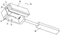
如图1至图10所示,本实施例的关节软组织平衡测量装置包括:基体10、抵顶件20和传动结构30。抵顶件20可移动地设置在基体10上,抵顶件20的侧壁上设置有刻度线25。传动结构30设置在基体10和抵顶件20之间。扭力螺丝刀40与传动结构30连接并通过传动结构30驱动抵顶件20上下移动,扭力螺丝刀40包括指示盘2及指示针,指示盘2上设置有标定抵顶件20受力值的刻度。As shown in FIGS. 1 to 10 , the joint soft tissue balance measurement device in this embodiment includes: a
应用本实施例的技术方案,扭力螺丝刀40与传动结构30连接并通过传动结构30驱动抵顶件20上下移动,扭力螺丝刀40包括指示盘2及指示针3,指示盘2上设置有标定抵顶件20受力值的刻度。在膝关节置换术中,当完成股骨及胫骨远端骨质切割后,将关节软组织平衡测量装置植入股骨与胫骨之间的截骨间隙中,旋转扭力螺丝刀40,扭力螺丝刀40驱动传动结构30转动。在传动结构30的作用下,抵顶件20上移,直至充满截骨间隙,以使抵顶件20与股骨髁截骨面接触配合,此时扭力螺丝刀40的指示盘2上的数值为零;当继续旋转扭力螺丝刀40,抵顶件20将向股骨髁截骨面施加抵顶力,抵顶件20首先克服关节的重力而后逐步上移并拉升韧带,直至韧带及周围软组织拉紧,如果抵顶件20继续加力,扭力螺丝刀的指示针的指示数值也逐渐上升,抵顶力将反应韧带及周围软组织的牵张力,牵张力和抵顶力是一对作用力反作用力,两值相等。在这个过程中,根据抵顶件20的侧壁上的刻度线25,可知抵顶件20上移的距离,此时观察指示针3在指示盘2上的指示数值,该指示数值为软组织的牵张力。当获得内侧副韧带和外侧副韧带两个区域的软组织的牵张力之后,根据两个区域的牵张力以及抵顶件20上移的距离,能够直观地、准确地判断是否需要对膝关节软组织的松解度进行调节,需要时,则平衡膝关节软组织的松解度。因此本实施例的技术方案有效地解决了相关技术中对软组织进行测力的准确度较差的问题。Applying the technical solution of this embodiment, the
如图3和图8所示,在本实施例中,传动结构30包括齿轮部31、第一齿条部32和第二齿条部33。齿轮部31与第一齿条部32和第二齿条部33相啮合,齿轮部31可移动地设置在第一齿条部32和第二齿条部33之间。第一齿条部32设置在基体10上,第二齿条部33设置在抵顶件20上,齿轮部31与扭力螺丝刀40连接。当扭力螺丝刀40旋拧齿轮部31时,齿轮部31在第一齿条部32和第二齿条部33作用下,可以上下移动,同时驱动抵顶件20沿着基体10上的第一齿条部32上下平移。这样,齿轮部31与第一齿条部32和第二齿条部33相啮合使得抵顶件20能够平稳地上下平移,并且具有准确地传动比,传动精度高。当然,在其他图中未示出的实施例中,传动结构还可以是链传动、带传动、蜗杆传动。As shown in FIGS. 3 and 8 , in this embodiment, the
如图1、图20至图22所示,在本实施例中,扭力螺丝刀40包括指示盘2及指示针,指示盘2上设置有标定抵顶件20受力值的刻度。需要说明的是,扭力螺丝刀又称扭力起子,是现有技术中的一种常用的工具。本申请中引用了该扭力螺丝刀的相应结构,并对扭力螺丝刀的指示盘上的刻度进行改进。具体地,参考图24,扭力螺丝刀包括套筒杆6、指示盘2、指示针3以及手柄1。指示盘2与套筒杆6固定连接,手柄1与指示针3固定连接。套筒杆6和手柄1为中空结构,并且嵌套设置,它们两个的内部通过扭力弹簧连接。套筒杆6与传动结构30连接,通过手柄1驱动传动结构30驱动抵顶件20移动。当抵顶件20将向股骨髁截骨面施加抵顶力时,扭力弹簧变形,推动指示针3活动,以使手柄1会带着指示针3相对套筒杆6和指示盘2转动,使指示针3停留在指示盘上的某一个数值上,通过指示针3在指示盘上的指示得到牵张力。扭力螺丝刀的具体结构可以参考授权公告号为CN203993676U的表盘式扭力螺丝刀或者授权公告号为CN207540706U的一种用于检测钢丝绳紧密性的测量装置。As shown in FIG. 1 , FIG. 20 to FIG. 22 , in this embodiment, the
现有技术中的扭力螺丝刀的表盘上显示的是扭矩值,本申请中对此处进行了改进,将扭矩值转化为压力值。可以通过力学试验机将扭矩值转化成压力值,将压力值标定在指示盘2上以形成显示抵顶件20受力值的刻度。具体地,图23示出了扭矩值和压力值的对应关系,横轴为扭矩值,纵轴为压力值。也即将原表盘上的0.2、0.4、0.8、1……3、3.2、3.4更改为45.00、77.00、97.00、132.00……442.00、446.00、460.00。当然上述数值仅为一种实施例,也可能因具体的结构差异和材质使得刻度有所差异。The torque value is displayed on the dial of the torque screwdriver in the prior art. In this application, an improvement is made to convert the torque value into a pressure value. The torque value can be converted into a pressure value by a mechanical testing machine, and the pressure value can be calibrated on the
可以将本实施例的关节软组织平衡测量装置的抵顶件20与力学试验机配合,扭转手柄1,使得指示针3指示至0.2、0.4、0.8、1……3、3.2、3.4,通过力学试验机的读数得到相应的压力值。这样,本申请使扭力螺丝刀40的指示盘2直接显示软组织的牵张力的压力值,更加直观反应出膝关节内侧或者外侧的软组织的牵张力的数值。The
本实施例的扭力螺丝刀40的套筒杆6为六棱体,齿轮部31上设置有与六棱体配合的六边孔,六棱体与六边孔插接配合,这样连接方便。The
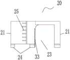
如图3、图8、图12和图19所示,在本实施例中,基体10包括底板12及设置在底板12上的第一凸出部13,抵顶件20包括抵顶块22和设置在抵顶块22上的凹槽23。第一凸出部13位于凹槽23内,齿轮部31位于第一凸出部13的侧壁和凹槽23的槽壁之间。第一齿条部32设置在第一凸出部13朝向齿轮部31的侧壁上,第二齿条部33设置在凹槽23朝向齿轮部31的槽壁上。凹槽23的设置能够避让第一凸出部13,以使第一凸出部13插入至凹槽23内。齿轮部31位于第一凸出部13的侧壁和凹槽23的槽壁之间使得关节软组织平衡测量装置结构紧凑、简单,占用空间较小,并且操作方便。As shown in FIG. 3 , FIG. 8 , FIG. 12 and FIG. 19 , in this embodiment, the
如图8、图11至图15所示,在本实施例中,基体10包括底板12及设置在底板12上的围板16。抵顶件20位于围板16的内部,传动结构30位于底板12和抵顶件20之间。围板16能够限定抵顶件20的活动范围,防止抵顶件20在水平方向上脱离围板16。As shown in FIGS. 8 , 11 to 15 , in this embodiment, the
如图3、图5、图8和图14所示,在本实施例中,围板16的内壁上设置有第一导向平面11,抵顶件20的外壁上设置有与第一导向平面11接触配合的第二导向平面21。第一导向平面11与第二导向平面21接触配合一方面能够使抵顶件20在围板16内移动更加的顺畅,另一方面能够防止抵顶件20相对于围板16产生转动。As shown in FIG. 3 , FIG. 5 , FIG. 8 and FIG. 14 , in this embodiment, the inner wall of the
如图3、图8、图10、图13、图15至图19所示,在本实施例中,抵顶件20包括抵顶块22和设置在抵顶块22的底部上的第二凸出部24。第二齿条部33的一部分位于第二凸出部24上,基体10上设置有能够避让第二凸出部24的避让部14。第二凸出部24的设置能够在保持整体结构紧凑性的情况下增加抵顶块22的高度,使第一齿条部32的布置长度能够延伸在第二凸出部24上,进而使齿轮部31具有足够的升降高度,以增加抵顶块22的移动范围。同时,避让部14的设置能够避让第二凸出部24,在增加抵顶块22的移动范围时,能够保证第二凸出部24与基体10之间不产生干涉。需要说明的是,避让部14设置在底板12上,避让部14为贯通孔,贯通孔的两端分别贯通底板12的上下的两个表面。As shown in FIG. 3 , FIG. 8 , FIG. 10 , FIG. 13 , FIG. 15 to FIG. 19 , in this embodiment, the abutting
本实施例的第二凸出部24为三个,避让部14为三个,三个第二凸出部24与三个避让部14一一对应地设置。三个第二凸出部24中位于中间的一个第二凸出部24上布置上述的第二齿条部33的一部分。当然,在其他图中未示出的实施例中,第二凸出部数量不限于三个、还可以是一个、两个、四个及以上,对应的避让部的数量与第二凸出部数量保持一致即可。In this embodiment, there are three second protruding
如图1、图6、图14和图16所示,在本实施例中,关节软组织平衡测量装置还包括防脱结构50,防脱结构50设置在基体10和抵顶件20之间。防脱结构50的设置能够在抵顶件20上移幅度过大的情况下,防止抵顶件20脱离基体10。防脱结构50包括止挡件51和与止挡件51配合的止挡槽52,止挡件51设置基体10上,止挡槽52设置在抵顶件20上。止挡件51为穿设在基体10上的销钉。在抵顶件20上移的过程中,当止挡件51与止挡槽52的槽侧壁接触时,此位置为抵顶件20上移的极限位置。本实施例的止挡槽52的一端贯通抵顶件20的顶面,这样抵顶件20的顶面能够避让止挡件51,便于止挡件51在上下方向上穿入至止挡槽52内。As shown in FIG. 1 , FIG. 6 , FIG. 14 and FIG. 16 , in this embodiment, the articular soft tissue balance measurement device further includes a
如图2、图7、图16和图17,抵顶件20的侧壁上设置有刻度线25。刻度线25的设置可以读取抵顶件20的上升高度,同时能够读取关节软组织平衡测量装置的整体高度。As shown in FIG. 2 , FIG. 7 , FIG. 16 and FIG. 17 , a
如图2、图6、图10至图12所示,在本实施例中,基体10的外壁面上设置有多个刻线15,多个刻线15沿竖直方向布置在基体10上。刻线15的设置可以作为刻度线25上升或者下降距离的参考线或者齿轮部31移动高度的参考线。As shown in FIG. 2 , FIG. 6 , and FIGS. 10 to 12 , in this embodiment, a plurality of
如图1至图15所示,在本实施例中,关节软组织平衡测量装置还包括握持件60,握持件60连接在基体10上。握持件60的设置便于控制基体10,以使基体10能够保持在截骨间隙中的指定位置处。As shown in FIG. 1 to FIG. 15 , in this embodiment, the device for measuring the balance of joint soft tissue further includes a holding
如图1、图4、图9和图19所示,在本实施例中,凹槽23贯穿抵顶块22的相对设置的两个侧面。这样凹槽23的两端能够避让齿轮部31的轴部,其中凹槽23的一端还能够避让扭力螺丝刀40,以使扭力螺丝刀40能够穿过抵顶块22。As shown in FIG. 1 , FIG. 4 , FIG. 9 and FIG. 19 , in this embodiment, the
如图2、图12、图17和图21所示,基体10的高度H1为15mm左右,抵顶件20总移动高度H2为14mm~25mm,第一凸出部13的顶面与基体10的顶面之间的距离H3为2mm左右,基体10的宽度L为30mm左右,齿轮部31的轴部的直径为4mm~12mm。上述的尺寸使得关节软组织平衡测量装置能够满足膝关节置换的截骨间隙的尺寸要求。As shown in FIG. 2 , FIG. 12 , FIG. 17 and FIG. 21 , the height H1 of the
在本发明的描述中,需要理解的是,方位词如“前、后、上、下、左、右”、“横向、竖向、垂直、水平”和“顶、底”等所指示的方位或位置关系通常是基于附图所示的方位或位置关系,仅是为了便于描述本发明和简化描述,在未作相反说明的情况下,这些方位词并不指示和暗示所指的装置或元件必须具有特定的方位或者以特定的方位构造和操作,因此不能理解为对本发明保护范围的限制;方位词“内、外”是指相对于各部件本身的轮廓的内外。In the description of the present invention, it should be understood that the orientations indicated by orientation words such as "front, rear, top, bottom, left, right", "horizontal, vertical, vertical, horizontal" and "top, bottom" etc. Or the positional relationship is usually based on the orientation or positional relationship shown in the drawings, which is only for the convenience of describing the present invention and simplifying the description, and these orientation words do not indicate or imply the indicated device or element unless otherwise stated. It must have a specific orientation or be constructed and operated in a specific orientation, so it cannot be construed as a limitation on the protection scope of the present invention; the orientation words "inside and outside" refer to the inside and outside relative to the outline of each component itself.
为了便于描述,在这里可以使用空间相对术语,如“在……之上”、“在……上方”、“在……上表面”、“上面的”等,用来描述如在图中所示的一个器件或特征与其他器件或特征的空间位置关系。应当理解的是,空间相对术语旨在包含除了器件在图中所描述的方位之外的在使用或操作中的不同方位。例如,如果附图中的器件被倒置,则描述为“在其他器件或构造上方”或“在其他器件或构造之上”的器件之后将被定位为“在其他器件或构造下方”或“在其他器件或构造之下”。因而,示例性术语“在……上方”可以包括“在……上方”和“在……下方”两种方位。该器件也可以其他不同方式定位(旋转90度或处于其他方位),并且对这里所使用的空间相对描述作出相应解释。For ease of description, spatially relative terms, such as "on", "over", "on the surface", "above", etc., may be used herein to describe what is shown in the figures. The spatial positional relationship of one device or feature shown to other devices or features. It should be understood that spatially relative terms are intended to encompass different orientations of the device in use or operation in addition to the orientation depicted in the figures. For example, if the device in the figures is turned over, elements described as "above" or "over" other devices or features would then be oriented "below" or "over" the other devices or features under other devices or constructions". Thus, the exemplary term "above" can encompass both an orientation of "above" and "below." The device may also be otherwise oriented (rotated 90 degrees or at other orientations) and the spatially relative descriptions used herein interpreted accordingly.
此外,需要说明的是,使用“第一”、“第二”等词语来限定零部件,仅仅是为了便于对相应零部件进行区别,如没有另行声明,上述词语并没有特殊含义,因此不能理解为对本发明保护范围的限制。In addition, it should be noted that the use of words such as "first" and "second" to define components is only for the convenience of distinguishing corresponding components. Unless otherwise stated, the above words have no special meaning and therefore cannot be understood to limit the scope of protection of the present invention.
以上所述仅为本发明的优选实施例而已,并不用于限制本发明,对于本领域的技术人员来说,本发明可以有各种更改和变化。凡在本发明的精神和原则之内,所作的任何修改、等同替换、改进等,均应包含在本发明的保护范围之内。The above descriptions are only preferred embodiments of the present invention, and are not intended to limit the present invention. For those skilled in the art, the present invention may have various modifications and changes. Any modification, equivalent replacement, improvement, etc. made within the spirit and principle of the present invention shall be included within the protection scope of the present invention.
Claims (10)
Priority Applications (1)
| Application Number | Priority Date | Filing Date | Title |
|---|---|---|---|
| CN202010491605.0ACN111568449B (en) | 2020-06-02 | 2020-06-02 | Joint soft tissue balance measurement device |
Applications Claiming Priority (1)
| Application Number | Priority Date | Filing Date | Title |
|---|---|---|---|
| CN202010491605.0ACN111568449B (en) | 2020-06-02 | 2020-06-02 | Joint soft tissue balance measurement device |
Publications (2)
| Publication Number | Publication Date |
|---|---|
| CN111568449Atrue CN111568449A (en) | 2020-08-25 |
| CN111568449B CN111568449B (en) | 2025-02-11 |
Family
ID=72109792
Family Applications (1)
| Application Number | Title | Priority Date | Filing Date |
|---|---|---|---|
| CN202010491605.0AActiveCN111568449B (en) | 2020-06-02 | 2020-06-02 | Joint soft tissue balance measurement device |
Country Status (1)
| Country | Link |
|---|---|
| CN (1) | CN111568449B (en) |
Cited By (1)
| Publication number | Priority date | Publication date | Assignee | Title |
|---|---|---|---|---|
| CN113440317A (en)* | 2021-06-29 | 2021-09-28 | 天衍医疗器材有限公司 | Gap balance measurer |
Citations (9)
| Publication number | Priority date | Publication date | Assignee | Title |
|---|---|---|---|---|
| CN200948140Y (en)* | 2006-09-08 | 2007-09-19 | 深圳市福田区中医院 | Means for measuring balance of full knee joint replacing parenchyma |
| CN201299556Y (en)* | 2008-12-03 | 2009-09-02 | 徐辉 | A medial-lateral balance tension measuring device for knee joint |
| CN105769119A (en)* | 2015-07-06 | 2016-07-20 | 微创骨科医疗科技(苏州)有限公司 | Knee joint soft tissue balance measuring device and measuring method thereof |
| CN105919607A (en)* | 2016-04-08 | 2016-09-07 | 爱乔(上海)医疗科技有限公司 | Human body knee joint soft tissue pressure and track measurement system |
| CN106037770A (en)* | 2016-06-23 | 2016-10-26 | 北京爱康宜诚医疗器材有限公司 | Soft tissue force measuring device |
| CN205924047U (en)* | 2016-06-23 | 2017-02-08 | 北京爱康宜诚医疗器材有限公司 | Soft tissue measuring force device |
| CN107157589A (en)* | 2017-05-22 | 2017-09-15 | 北京爱康宜诚医疗器材有限公司 | Soft tissue balance device for measuring force |
| CN107693065A (en)* | 2017-11-07 | 2018-02-16 | 北京蒙太因医疗器械有限公司 | Knee space retractor |
| CN212394935U (en)* | 2020-06-02 | 2021-01-26 | 北京爱康宜诚医疗器材有限公司 | Joint soft tissue balance measuring device |
- 2020
- 2020-06-02CNCN202010491605.0Apatent/CN111568449B/enactiveActive
Patent Citations (9)
| Publication number | Priority date | Publication date | Assignee | Title |
|---|---|---|---|---|
| CN200948140Y (en)* | 2006-09-08 | 2007-09-19 | 深圳市福田区中医院 | Means for measuring balance of full knee joint replacing parenchyma |
| CN201299556Y (en)* | 2008-12-03 | 2009-09-02 | 徐辉 | A medial-lateral balance tension measuring device for knee joint |
| CN105769119A (en)* | 2015-07-06 | 2016-07-20 | 微创骨科医疗科技(苏州)有限公司 | Knee joint soft tissue balance measuring device and measuring method thereof |
| CN105919607A (en)* | 2016-04-08 | 2016-09-07 | 爱乔(上海)医疗科技有限公司 | Human body knee joint soft tissue pressure and track measurement system |
| CN106037770A (en)* | 2016-06-23 | 2016-10-26 | 北京爱康宜诚医疗器材有限公司 | Soft tissue force measuring device |
| CN205924047U (en)* | 2016-06-23 | 2017-02-08 | 北京爱康宜诚医疗器材有限公司 | Soft tissue measuring force device |
| CN107157589A (en)* | 2017-05-22 | 2017-09-15 | 北京爱康宜诚医疗器材有限公司 | Soft tissue balance device for measuring force |
| CN107693065A (en)* | 2017-11-07 | 2018-02-16 | 北京蒙太因医疗器械有限公司 | Knee space retractor |
| CN212394935U (en)* | 2020-06-02 | 2021-01-26 | 北京爱康宜诚医疗器材有限公司 | Joint soft tissue balance measuring device |
Cited By (2)
| Publication number | Priority date | Publication date | Assignee | Title |
|---|---|---|---|---|
| CN113440317A (en)* | 2021-06-29 | 2021-09-28 | 天衍医疗器材有限公司 | Gap balance measurer |
| CN113440317B (en)* | 2021-06-29 | 2022-11-22 | 天衍医疗器材有限公司 | Gap balance measurer |
Also Published As
| Publication number | Publication date |
|---|---|
| CN111568449B (en) | 2025-02-11 |
Similar Documents
| Publication | Publication Date | Title |
|---|---|---|
| EP3007629B1 (en) | Improvements in or relating to assemblies for use in knee replacement surgery | |
| CN105769119B (en) | Knee joint soft tissue balance measuring device and measuring method | |
| US5733292A (en) | Arthroplasty trial prosthesis alignment devices and associated methods | |
| EP3270832B1 (en) | A surgical aid for joints | |
| US9615887B2 (en) | Bone cutting system for the leg and method therefor | |
| US4583555A (en) | Knee ligament testing system | |
| EP3928720A1 (en) | Distal femoral condyle bone defect osteotomy guide | |
| US20110213275A1 (en) | Device for determining the stability of a knee joint | |
| CN107961056B (en) | Force line measuring angle positioning device for osteotomy around knee joint | |
| WO1997009939A9 (en) | Arthroplasty trial prosthesis, alignment devices and associated methods | |
| KR101125230B1 (en) | Gap measuring device for artificial knee joint | |
| CN107252309A (en) | Telemetic orthopaedic implant | |
| CN213821413U (en) | Knee joint replacement surgery caliber | |
| US10849551B2 (en) | Integrated ligament strain measurement | |
| CN111743599A (en) | osteotomy device | |
| CN111568449A (en) | Joint soft tissue balance measurement device | |
| CN212394935U (en) | Joint soft tissue balance measuring device | |
| CN212395006U (en) | osteotomy device | |
| CN212394934U (en) | Joint soft tissue balance measuring device | |
| CN111568448A (en) | Joint soft tissue balance measuring device | |
| WO2017220173A1 (en) | Integrated ligament strain measurement | |
| CN213371932U (en) | Joint soft tissue balance measuring device | |
| CN111714166B (en) | Multi-functional caliber that struts of orthopedics | |
| GB2526724A (en) | Improvements in or relating to assemblies for use in knee replacement surgery | |
| TWI795335B (en) | Methods for Designing Surgical Instruments |
Legal Events
| Date | Code | Title | Description |
|---|---|---|---|
| PB01 | Publication | ||
| PB01 | Publication | ||
| SE01 | Entry into force of request for substantive examination | ||
| SE01 | Entry into force of request for substantive examination | ||
| GR01 | Patent grant | ||
| GR01 | Patent grant |