CN111565769A - Combined hanger arm extension part for wound treatment device and pump cover - Google Patents
Combined hanger arm extension part for wound treatment device and pump coverDownload PDFInfo
- Publication number
- CN111565769A CN111565769ACN201880082872.3ACN201880082872ACN111565769ACN 111565769 ACN111565769 ACN 111565769ACN 201880082872 ACN201880082872 ACN 201880082872ACN 111565769 ACN111565769 ACN 111565769A
- Authority
- CN
- China
- Prior art keywords
- hanger arm
- sleeve
- pump
- extending
- hook
- Prior art date
- Legal status (The legal status is an assumption and is not a legal conclusion. Google has not performed a legal analysis and makes no representation as to the accuracy of the status listed.)
- Granted
Links
Images


Classifications
- A—HUMAN NECESSITIES
- A61—MEDICAL OR VETERINARY SCIENCE; HYGIENE
- A61M—DEVICES FOR INTRODUCING MEDIA INTO, OR ONTO, THE BODY; DEVICES FOR TRANSDUCING BODY MEDIA OR FOR TAKING MEDIA FROM THE BODY; DEVICES FOR PRODUCING OR ENDING SLEEP OR STUPOR
- A61M1/00—Suction or pumping devices for medical purposes; Devices for carrying-off, for treatment of, or for carrying-over, body-liquids; Drainage systems
- A61M1/90—Negative pressure wound therapy devices, i.e. devices for applying suction to a wound to promote healing, e.g. including a vacuum dressing
- A61M1/91—Suction aspects of the dressing
- A—HUMAN NECESSITIES
- A61—MEDICAL OR VETERINARY SCIENCE; HYGIENE
- A61F—FILTERS IMPLANTABLE INTO BLOOD VESSELS; PROSTHESES; DEVICES PROVIDING PATENCY TO, OR PREVENTING COLLAPSING OF, TUBULAR STRUCTURES OF THE BODY, e.g. STENTS; ORTHOPAEDIC, NURSING OR CONTRACEPTIVE DEVICES; FOMENTATION; TREATMENT OR PROTECTION OF EYES OR EARS; BANDAGES, DRESSINGS OR ABSORBENT PADS; FIRST-AID KITS
- A61F13/00—Bandages or dressings; Absorbent pads
- A61F13/05—Bandages or dressings; Absorbent pads specially adapted for use with sub-pressure or over-pressure therapy, wound drainage or wound irrigation, e.g. for use with negative-pressure wound therapy [NPWT]
- A—HUMAN NECESSITIES
- A61—MEDICAL OR VETERINARY SCIENCE; HYGIENE
- A61M—DEVICES FOR INTRODUCING MEDIA INTO, OR ONTO, THE BODY; DEVICES FOR TRANSDUCING BODY MEDIA OR FOR TAKING MEDIA FROM THE BODY; DEVICES FOR PRODUCING OR ENDING SLEEP OR STUPOR
- A61M1/00—Suction or pumping devices for medical purposes; Devices for carrying-off, for treatment of, or for carrying-over, body-liquids; Drainage systems
- A61M1/71—Suction drainage systems
- A61M1/77—Suction-irrigation systems
- A—HUMAN NECESSITIES
- A61—MEDICAL OR VETERINARY SCIENCE; HYGIENE
- A61M—DEVICES FOR INTRODUCING MEDIA INTO, OR ONTO, THE BODY; DEVICES FOR TRANSDUCING BODY MEDIA OR FOR TAKING MEDIA FROM THE BODY; DEVICES FOR PRODUCING OR ENDING SLEEP OR STUPOR
- A61M1/00—Suction or pumping devices for medical purposes; Devices for carrying-off, for treatment of, or for carrying-over, body-liquids; Drainage systems
- A61M1/90—Negative pressure wound therapy devices, i.e. devices for applying suction to a wound to promote healing, e.g. including a vacuum dressing
- A61M1/92—Negative pressure wound therapy devices, i.e. devices for applying suction to a wound to promote healing, e.g. including a vacuum dressing with liquid supply means
- A—HUMAN NECESSITIES
- A61—MEDICAL OR VETERINARY SCIENCE; HYGIENE
- A61M—DEVICES FOR INTRODUCING MEDIA INTO, OR ONTO, THE BODY; DEVICES FOR TRANSDUCING BODY MEDIA OR FOR TAKING MEDIA FROM THE BODY; DEVICES FOR PRODUCING OR ENDING SLEEP OR STUPOR
- A61M3/00—Medical syringes, e.g. enemata; Irrigators
- A61M3/02—Enemata; Irrigators
- A61M3/0233—Enemata; Irrigators characterised by liquid supply means, e.g. from pressurised reservoirs
- A61M3/0254—Enemata; Irrigators characterised by liquid supply means, e.g. from pressurised reservoirs the liquid being pumped
- A61M3/0258—Enemata; Irrigators characterised by liquid supply means, e.g. from pressurised reservoirs the liquid being pumped by means of electric pumps
- A—HUMAN NECESSITIES
- A61—MEDICAL OR VETERINARY SCIENCE; HYGIENE
- A61F—FILTERS IMPLANTABLE INTO BLOOD VESSELS; PROSTHESES; DEVICES PROVIDING PATENCY TO, OR PREVENTING COLLAPSING OF, TUBULAR STRUCTURES OF THE BODY, e.g. STENTS; ORTHOPAEDIC, NURSING OR CONTRACEPTIVE DEVICES; FOMENTATION; TREATMENT OR PROTECTION OF EYES OR EARS; BANDAGES, DRESSINGS OR ABSORBENT PADS; FIRST-AID KITS
- A61F13/00—Bandages or dressings; Absorbent pads
- A61F2013/00089—Wound bandages
- A—HUMAN NECESSITIES
- A61—MEDICAL OR VETERINARY SCIENCE; HYGIENE
- A61M—DEVICES FOR INTRODUCING MEDIA INTO, OR ONTO, THE BODY; DEVICES FOR TRANSDUCING BODY MEDIA OR FOR TAKING MEDIA FROM THE BODY; DEVICES FOR PRODUCING OR ENDING SLEEP OR STUPOR
- A61M2205/00—General characteristics of the apparatus
- A61M2205/33—Controlling, regulating or measuring
- A61M2205/3331—Pressure; Flow
- A61M2205/3344—Measuring or controlling pressure at the body treatment site
- A—HUMAN NECESSITIES
- A61—MEDICAL OR VETERINARY SCIENCE; HYGIENE
- A61M—DEVICES FOR INTRODUCING MEDIA INTO, OR ONTO, THE BODY; DEVICES FOR TRANSDUCING BODY MEDIA OR FOR TAKING MEDIA FROM THE BODY; DEVICES FOR PRODUCING OR ENDING SLEEP OR STUPOR
- A61M2209/00—Ancillary equipment
- A61M2209/08—Supports for equipment
- A61M2209/082—Mounting brackets, arm supports for equipment
- A—HUMAN NECESSITIES
- A61—MEDICAL OR VETERINARY SCIENCE; HYGIENE
- A61M—DEVICES FOR INTRODUCING MEDIA INTO, OR ONTO, THE BODY; DEVICES FOR TRANSDUCING BODY MEDIA OR FOR TAKING MEDIA FROM THE BODY; DEVICES FOR PRODUCING OR ENDING SLEEP OR STUPOR
- A61M3/00—Medical syringes, e.g. enemata; Irrigators
- A61M3/02—Enemata; Irrigators
- A61M3/0201—Cassettes therefor
- A—HUMAN NECESSITIES
- A61—MEDICAL OR VETERINARY SCIENCE; HYGIENE
- A61M—DEVICES FOR INTRODUCING MEDIA INTO, OR ONTO, THE BODY; DEVICES FOR TRANSDUCING BODY MEDIA OR FOR TAKING MEDIA FROM THE BODY; DEVICES FOR PRODUCING OR ENDING SLEEP OR STUPOR
- A61M3/00—Medical syringes, e.g. enemata; Irrigators
- A61M3/02—Enemata; Irrigators
- A61M3/0204—Physical characteristics of the irrigation fluid, e.g. conductivity or turbidity
- A61M3/0208—Physical characteristics of the irrigation fluid, e.g. conductivity or turbidity before use
- A—HUMAN NECESSITIES
- A61—MEDICAL OR VETERINARY SCIENCE; HYGIENE
- A61M—DEVICES FOR INTRODUCING MEDIA INTO, OR ONTO, THE BODY; DEVICES FOR TRANSDUCING BODY MEDIA OR FOR TAKING MEDIA FROM THE BODY; DEVICES FOR PRODUCING OR ENDING SLEEP OR STUPOR
- A61M3/00—Medical syringes, e.g. enemata; Irrigators
- A61M3/02—Enemata; Irrigators
- A61M3/0204—Physical characteristics of the irrigation fluid, e.g. conductivity or turbidity
- A61M3/022—Volume; Flow rate
Landscapes
- Health & Medical Sciences (AREA)
- Heart & Thoracic Surgery (AREA)
- General Health & Medical Sciences (AREA)
- Engineering & Computer Science (AREA)
- Biomedical Technology (AREA)
- Life Sciences & Earth Sciences (AREA)
- Animal Behavior & Ethology (AREA)
- Public Health (AREA)
- Veterinary Medicine (AREA)
- Anesthesiology (AREA)
- Hematology (AREA)
- Vascular Medicine (AREA)
- Pulmonology (AREA)
- Infusion, Injection, And Reservoir Apparatuses (AREA)
- Medical Preparation Storing Or Oral Administration Devices (AREA)
Abstract
Description
Cross Reference to Related Applications
This application claims priority to U.S. provisional application No. 62/608,339 filed on 20.12.2017, which is incorporated herein by reference in its entirety.
Background
The present disclosure relates generally to wound therapy systems and devices, and more particularly to hanger arm extensions and pump caps for negative pressure and instillation wound therapy devices.
Negative pressure wound therapy with instillation (NPTWi) is one type of wound therapy that involves the application of negative pressure (relative to atmospheric pressure) and an amount of instillation fluid to a wound site to promote wound healing. The instillation fluid may be provided to the NPTWI system from an instillation fluid container. Some NPTWi systems include hanger arms that allow an instillation fluid container to be hung near the NPTWi system. The configuration of the hanger arms may limit the shape or size of the fluid container that may be used with the system. Some NPTWi systems include a peristaltic pump that controls the flow of instillation fluid to the wound site. When the NPTWi system is not in use, the peristaltic pump may be exposed and prone to damage.
SUMMARY
One embodiment of the present disclosure is a combination hanger arm extension and pump cap arrangement for use with a drip unit. The device includes a body portion having a first end and a second end. A hook extends from the first end and a tab extends from the body adjacent the hook. The panel is disposed proximate the second end. A substantially rectangular sleeve extends at least partially through the body. The sleeve is disposed between the first end and the second end.
In some embodiments, the tab includes a ridge that protrudes toward the hook. In some embodiments, the body is formed as a single, unitary piece. In some embodiments, the body includes a pair of substantially parallel first sidewalls. The first side walls define a U-shaped channel therebetween and extend between the first end of the body and the sleeve.
In some embodiments, the body further comprises a flange extending from a free edge of the first sidewall. In some embodiments, the sleeve has an axis extending substantially transverse to the longitudinal axis of the body, and may include a notch extending along an inner wall of the sleeve. The body may also include a wall closing one end of the sleeve. A slot may be formed in the wall and the slot may have a first end substantially aligned with the notch in the sleeve.
In some embodiments, the sleeve is configured to receive a substantially rectangular hanger arm extending from the drip unit. The slot may be configured to resiliently engage a tab extending from an end of the hanger arm. The sleeve may be configured to apply a clamping force to the hanger arm when a force is applied to the hook. The notch may be configured to substantially receive a protrusion extending from an end of the hanger arm when the sleeve receives the hanger arm. In some embodiments, the hook is configured to hold a container of instillation fluid when the sleeve receives the hanger arm.
In some embodiments, the panel includes a latch structure proximate a free end of the panel. The latch structure includes at least one substantially circular tab. The latch structure and the tab are configured to resiliently and removably engage a correspondingly shaped recess on the drip unit. In some embodiments, the body is configured to substantially cover the pump device on the drip unit when the latch structure and tab are engaged with the correspondingly shaped recess.
In some embodiments, the body includes a pair of substantially parallel second sidewalls. The second side walls and the panel define a U-shaped opening therebetween.
Another embodiment of the present disclosure is a negative pressure and instillation wound therapy device. The negative pressure and instillation wound therapy device includes a housing having a console with a user interface. A first pump is disposed within the housing and is configured to draw negative pressure on the wound site. A second pump is disposed within the housing. The second pump is configured to aspirate a quantity of instillation fluid from the fluid container and deliver the instillation fluid to the wound site. A bracket is disposed on the housing adjacent the second pump. The cassette may engage with the brackets when the wound treatment apparatus is in use. The cassette is configured to direct the quantity of instillation fluid to the second pump. The cassette is removable from the brackets when the wound treatment apparatus is not in use. The wound treatment apparatus also includes an extendable and retractable hanger arm coupled to the housing. A combination hanger arm extension and pump cap may be engaged with the hanger arm and may support the fluid container when the wound therapy device is in use. A combination hanger arm extension and pump cover may also be engaged with the brackets to substantially cover the second pump when the wound treatment apparatus is not in use.
In some embodiments, the combination hanger arm extension and pump cap further includes a main body portion having a first end and a second end, a hook extending from the first end, a tab extending from the main body proximate the hook, and a panel disposed proximate the second end. A substantially rectangular sleeve extends at least partially through the body. The sleeve is disposed between the first end and the second end. In some embodiments, the sleeve is configured to receive the hanger arm.
Drawings
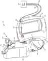
Fig. 1 is a front perspective view of a negative pressure and instillation wound therapy system including a combination hanger arm extension and pump cap device shown in use, according to an exemplary embodiment.
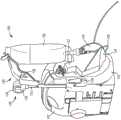
FIG. 2 is a rear perspective view of the system of FIG. 1 including a combination hanger arm extension and pump cap arrangement and cassette, according to an exemplary embodiment.
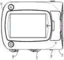
Fig. 3 is a view of the drip unit of fig. 1-2 in an unused state with the cassette removed, according to an exemplary embodiment.
Fig. 4 is a front view of the drip unit of fig. 3 according to an exemplary embodiment.
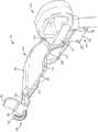
Fig. 5 is a detailed front perspective view of the hanger arm extension and pump cap device of fig. 1-2, which function as a hanger arm extension, according to an exemplary embodiment.
Fig. 6 is a detailed rear perspective view of the hanger arm extension and pump cap device of fig. 1-2, which functions as a hanger arm extension, according to an exemplary embodiment.
Fig. 7 is a view of a hanger arm extension and a pump cap device that function as a pump cap and the instillation unit of fig. 3 in an unused state according to an exemplary embodiment.
Fig. 8A is a top perspective view of the hanger arm extension and pump cap arrangement of fig. 1-2 and 5-7, according to an exemplary embodiment.
Fig. 8B is a bottom perspective view of the hanger arm extension and pump cap arrangement of fig. 1-2 and 5-7, according to an exemplary embodiment.
Fig. 8C is a right side view of the hanger arm extension and pump cap arrangement of fig. 1-2 and 5-7, according to an exemplary embodiment.
Fig. 8D is a detailed view of a hanger arm extension and a portion of a pump cap arrangement of fig. 8C, according to an example embodiment.
Fig. 8E is a left side view of the hanger arm extension and pump cap arrangement of fig. 1-2 and 5-7, according to an exemplary embodiment.
Fig. 8F is a top view of the hanger arm extension and pump cap arrangement of fig. 1-2 and 5-7, according to an exemplary embodiment.
Detailed Description
Overview
Referring generally to the drawings, a hanger arm extension and pump cap arrangement for use with a negative pressure wound therapy unit with instillation and components thereof is shown according to an exemplary embodiment. Hanger arm and pump cover device include: the clip includes a body portion having a first end and a second end, a hook extending from the first end, a tab extending from the body proximate the hook, a panel disposed proximate the second end, and a substantially rectangular sleeve extending at least partially through the body. The sleeve is disposed between the first end and the second end.
Negative pressure and instillation wound therapy system
Referring now to fig. 1 and 2, a negative pressure wound therapy with instillation (NPTWi)system 100 is shown in use. TheNPTWi system 100 is shown to include a negative pressure and instillation wound therapy unit (instillation unit) 102 that is fluidly connected to awound site 104 via avacuum tubing 106 and aninstillation fluid tubing 108. Thewound site 104 may include a tissue wound and a wound dressing covering the tissue wound and covering the patient's skin.
Theinstillation unit 102 may be configured to provide negative pressure wound therapy by reducing pressure at thewound site 104. Theinstillation unit 102 can draw a vacuum or negative pressure (relative to atmospheric pressure) at thewound site 104 by removing wound exudate, air, and other fluids from thewound site 104 via thevacuum tubing 106. Wound exudate, air, and other fluids from thewound site 104 pass through thevacuum tubing 106 and collect in thecanister 110 on theleft side 112 of thedrip unit 102. Wound exudate may include fluid that is filtered from the patient's circulatory system into the diseased or inflamed area. For example, wound exudate may include water and dissolved solutes such as blood, plasma proteins, white blood cells, platelets, and red blood cells. Other fluids removed from thewound site 104 may include instillation fluids previously delivered to thewound site 104.
Theinstillation unit 102 may also be configured to provide instillation fluid to thewound site 104 via aninstillation fluid conduit 108. For example, instillation fluids may include cleansing fluids, prescription fluids, medicinal fluids, antimicrobial fluids, irrigation fluids, or any other type of fluid that may be delivered to thewound site 104 during wound therapy. Thedrip unit 102 may use a pump, such as a peristaltic pump 114 (shown more clearly in fig. 3), accessible from theright side 116 of thedrip unit 102 to control the timing and volume of the instillation fluid provided to thewound site 104. Options for controlling the timing and volume of instillation fluid provided to thewound site 104 may be provided on theuser interface 118.
The instillation fluid can originate from any instillation fluid container, such as thesolution bag 120 as shown. Thesolution bag 120 is fluidly coupled to thedrip fluid tubing 108. The drip fluid may flow through thedrip fluid tubing 108, which is directed into thecassette body 122. Thecassette 122 directs thedrip fluid tubing 108 to the peristaltic pump 114 (shown in fig. 3) located along theright side 116 of thedrip unit 102 below thecassette 122. Theinstillation fluid line 108 then exits the top of thecassette 122 and extends toward thewound site 104. Thecassette body 122 has sidewalls 124 that form a recess configured to receive a container of drip fluid. Thecassette 122 may be a single-use or limited-use consumable part that is removably coupled to thedrip unit 102 such that the part may be removed after use. In some embodiments, thecartridge 122 must be removed and/or discarded after use for sterilization or other device safety and maintenance processes.
Referring now to fig. 3 and 4, a view of theinfusion unit 102 is shown in an unused state without thecassette 122 or hanger arm extension andpump cap arrangement 150. Therecess 140 is recessed into theright side 116 of thedrip unit 102 and is oriented substantially vertically along theright side 116. Therecess 140 has abottom end 142 and atop end 144. Acuff 146 is positioned withinrecess 140 proximatebottom end 142. Thecuff 146 may extend from therecess 140 and may extend from theright side 116. Theclip 148 is positioned proximate thetip 144. Theclip 148 may extend from therecess 140 and may extend from theright side 116. Theclip 148 andcuff 146 together form a bracket that is engageable with thecassette 122 as shown in fig. 1-2 and that is engageable with the hanger arm extension and pumpcap assembly 150 as shown in fig. 7.
Hanger arm extension and pump cover device
Referring now to fig. 5 and 6, a first detailed view of the hanger arm extension andpump cap arrangement 150 is shown. Thedevice 150 has abody 152 with afirst end 154 and asecond end 156. Thehook 158 extends at thefirst end 154, curving toward thetab 160. Atab 160 extends from thebody 152 proximate thehook 158 and is positioned between thehook 158 and thesecond end 156. Thetab 160 is shown bent slightly away from thehook 158. Aridge 162 extends from thetab 160 and projects toward thehook 158. Therigid ribs 164 support thetabs 160.
Thebody 152 includes twofirst sidewalls 166. Thefirst side walls 166 are substantially parallel and connected by atop wall 168 oriented perpendicular to thefirst side walls 166. Thetop wall 168 is aligned with the top edge of thefirst side wall 166. Thefirst side wall 166 and thetop wall 168 thereby combine to define aU-shaped channel 170 therebetween. Aflange 172 extends from theside wall 166 along a bottom edge of the first side wall 166 (i.e., along the opening of the U-shaped channel 170). Theflange 172 is oriented substantially perpendicular to thefirst sidewall 166 and is positioned outside the opening of theU-shaped channel 170.
Theside walls 166 and thetop wall 168 extend between thefirst end 154 of thebody 152 and thesleeve 174. Thesleeve 174 is disposed between thefirst end 154 and thesecond end 156. Thesleeve 174 is shown by way of example as having a substantially rectangular shape and extending at least partially through thebody 152. Thesleeve 174 has an axis extending substantially transverse to the longitudinal axis of thebody 152. Thesleeve 174 has arecess 176 extending along the inner wall of thesleeve 174. The notch is shown aligned with one end of thetop wall 168. Aslot 178 may extend through the wall of thesleeve 174.
In some embodiments, the cross-sectional shape of thesleeve 174 is substantially the same as the cross-sectional shape of thehanger arm 136 andhook 138, but may be slightly larger to allow thedevice 150 to slide on and off of thehanger arm 136. In some embodiments, the shape of thenotch 176,slot 178, and hook 138 help ensure that thesleeve 174 can only receive thehanger arm 136 in a single orientation. Theslot 178 may be shaped substantially similar to a cross-section of thehook 138 extending from thehanger arm 136 and may be substantially aligned with thenotch 176.
Thesleeve 174 is configured to receive thehanger arm 136 of thecradle 130 extending from thedrip unit 102.Notch 176 is configured to substantially accommodate passage ofhook 138 throughsleeve 174, andslot 178 allowshook 138 to pass out ofsleeve 174 andbody 152 whensleeve 174 receiveshanger arm 136.
As shown in fig. 5 and 6, when thesleeve 174 receives thehanger arm 136, thefirst end 154 is positioned generally above thehanger arm 136. Thebody 152 may also be oriented such that thefirst end 154 and thehook 158 are horizontally spaced from thehanger arm 136.
In this configuration, when a downward force is applied to the hook 158 (which rotates thebody 152 relative to the axis of the sleeve 174), slight rotation of thesleeve 174 relative to thehanger arm 136 results in a clamping force that substantially fixes thedevice 150 relative to thehanger arm 136. For example, the downward force may be gravity caused by suspending a container of instillation fluid (e.g., thesolution bag 120 as shown in fig. 6) from thehook 158. In some embodiments, theslot 178 resiliently engages thehook 138 to help secure thedevice 150 to thehanger arm 136. As shown in fig. 6,hook 158 is configured to securely hold a container of instillation fluid (shown as solution bag 120) whensleeve 174 receiveshanger arm 136.
The hanger arm extension andpump cap arrangement 150 also includes apanel 180 disposed proximate thesecond end 156 of themain body 152. As shown, thepanel 180 may be substantially planar. A pair of substantially parallelsecond side walls 186 extend from theface plate 180 to the sleeve. Thesecond side wall 186 and thepanel 180 define a U-shaped opening 188 therebetween. Thepanel 180 includes a latch structure, shown as acircular tab 182, positioned proximate the free end of the panel 180 (i.e., at thesecond end 156 of the body 152). Acircular tab 182 extends from thesecond end 156 of thebody 152 and across thesecond sidewall 186. As described in more detail below with reference to fig. 7, the latching structure (e.g., circular tab 182) andtab 160 are configured to resiliently and removably engage a correspondingly shaped recess on thedrip unit 102.
In some embodiments,flange 172 extends substantially fromfirst end 154 tosecond end 156. Theflange 172 extends from both thesecond side wall 186 and thefirst side wall 166 along the edges of theU-shaped channel 170 and the U-shaped opening 188. Theflange 172 may be substantially planar. In some embodiments,flange 172 includes anotch 200.Gap 200 is located betweenfirst end 154 andsleeve 174. Theindentations 200 may be substantially semicircular and configured to reflect the semicircular shape of theperistaltic pump 114 shown in fig. 1, 3-4, and 7.
Referring now to FIG. 7, a view ofNPTWi system 100 is shown in an unused state with hanger arm extensions andpump cap arrangement 150 deployed as a pump cap. The hanger arm extension andpump cap arrangement 150 is positioned to substantially cover therecess 140. More specifically, thefirst end 154 of themain body 152 is aligned with thetop end 144 of therecess 140. Thesecond end 156 of themain body 152 is aligned with thebottom end 142 of therecess 140. Acircular tab 182 positioned at thesecond end 156 of thebody 152 rotatably engages thecuff 146. When thecircular tab 182 is placed within thecuff 146, thebody 152 may be rotated about an axis defined by the circular tab (about thesecond end 156 of the body 152) toward or away from theright side 116 of thedrip unit 102. The hanger arm extensions andpump cap arrangement 150 are intended to protect theperistaltic pump 114 and minimize the ingress of contaminants during an unused state.
Thebody 152 may then be rotated toward theright side 116 until thetab 160 and theridge 162 engage theclip 148. Theclip 148 may be configured to receive theridge 162 when thetab 160 is pressed toward thebody 152. Thetab 160 may have a resilient or springing characteristic such that thetab 160 may flex slightly toward thebody 152 to allow theridge 162 to be received by theclip 148 in a "snap-fit" arrangement, and such that the tab springs back toward its original position when released to prevent theridge 162 from exiting theclip 148. Hanger arm extension and pumpcap assembly 150 thus engages the bracket formed bycuff 146 andclip 148. In some embodiments, thecassette 122 as shown in fig. 1-2 engages the cradle formed by thecuff 146 and theclip 148 using similar latching features.
When thecuff 146 engages thecircular tab 182 and theclip 148 engages thetab 160, theflange 172 is positioned substantially flush against theright side 116 of theinfusion unit 102 along therecess 140. Thenotch 200 receives the portion of theperistaltic pump 114 that extends from theright side 116 such that the flange is positioned substantially flush against the contour of theperistaltic pump 114. In this configuration, hanger arm extension andpump cap arrangement 150 substantially coversrecess 140 andperistaltic pump 114. Such a configuration may be advantageous when using theNPTWI system 100 without instillation therapy (i.e., only negative pressure therapy is required), or for shipping or storage of theNPTWI system 100. Substantially coveringrecess 140 and protectingperistaltic pump 114 helps to minimize cleaning and maintenance ofNPTWI system 100.
Referring now to fig. 8A-8F, a series of alternate views of the hanger arm andpump cap arrangement 150 are shown. The hanger arm extension and pumpcap assembly 150 may be formed as a single integral piece. Thedevice 150 may, for example, be made of a plastic having preferred properties in terms of impact resistance, chemical resistance, and rigidity, including, for example, polybutylene terephthalate. Thedevice 150 may be injection molded, 3-D printed, or manufactured using some other suitable process. Advantageously, thedevice 150 may thus be lightweight and inexpensive.
Theexterior surface 800 of thebody 152 may have a rough texture to facilitate grasping by a healthcare worker. Theinterior surface 802 of theU-shaped channel 170 and the U-shaped opening 188 may be smooth (i.e., non-textured), for example, to avoid the accumulation of contaminants and the like. Theinner wall 804 of thesleeve 174 may also be smooth (i.e., without texturing).
Configuration of the exemplary embodiment
The construction and arrangement of the systems and methods as shown in the various exemplary embodiments are illustrative only. Although only a few embodiments have been described in detail in this disclosure, many modifications are possible (e.g., variations in sizes, dimensions, structures, shapes and proportions of the various elements, values of parameters, mounting arrangements, use of materials, colors, orientations, etc.). For example, the positions of elements may be reversed or otherwise varied, and the nature or number of discrete elements or positions may be altered or varied. Accordingly, all such modifications are intended to be included within the scope of this disclosure. Other substitutions, modifications, changes and omissions may be made in the design, operating conditions and arrangement of the exemplary embodiments without departing from the scope of the present disclosure.
Claims (20)
1. A combination hanger arm extension and pump cover device for use with a wound treatment unit with instillation, the combination hanger arm extension and pump cover device comprising:
a body portion having a first end and a second end;
a hook extending from the first end;
a tab extending from the body proximate the hook;
a panel disposed proximate the second end; and
a substantially rectangular sleeve extending at least partially through the body, the sleeve disposed between the first end and the second end.
2. The device of claim 1, wherein the tab includes a ridge protruding toward the hook.
3. The device of claim 1, wherein the body is formed as a single unitary piece.
4. The device of claim 1, wherein the body includes a pair of substantially parallel first side walls, wherein the first side walls define a U-shaped channel therebetween and extend between the first end of the body and the sleeve.
5. The device of claim 4, wherein the body further comprises a flange extending from a free edge of the first sidewall.
6. The device of claim 1, wherein the sleeve has an axis extending substantially transverse to a longitudinal axis of the body.
7. The device of claim 6, wherein the sleeve further comprises a notch extending along an inner wall of the sleeve.
8. The device of claim 7, wherein the body further comprises a wall closing one end of the sleeve, the wall having a slot formed therein;
wherein the slot has a first end substantially aligned with the notch in the sleeve.
9. The apparatus of claim 7, wherein the sleeve is configured to receive a substantially rectangular hanger arm extending from the drip unit.
10. The apparatus of claim 9, wherein the slot is configured to resiliently engage a protrusion extending from an end of the hanger arm.
11. The apparatus of claim 9, wherein the sleeve is configured to apply a clamping force to the hanger arm when a force is applied to the hook.
12. The apparatus of claim 9, wherein the notch is configured to substantially receive a protrusion extending from an end of the hanger arm when the sleeve receives the hanger arm.
13. The apparatus of claim 9, wherein the hook is configured to hold a container of instillation fluid when the sleeve receives the hanger arm.
14. The device of claim 1, wherein the panel includes a latch structure proximate a free end of the panel, the latch structure including at least one substantially circular tab.
15. The device of claim 14, wherein the latching structure and tabs on the body are configured to resiliently and removably engage correspondingly shaped recesses on the drip unit.
16. The device of claim 15, wherein the body is configured to substantially cover a pump device on the drip unit when the latch structure and tab engage with the correspondingly shaped recess.
17. The device of claim 1, wherein the body comprises a pair of substantially parallel second side walls, wherein the second side walls and the panel define a U-shaped opening therebetween.
18. A negative pressure wound therapy device with instillation, the device comprising:
a housing having a console with a user interface;
a first pump disposed within the housing and configured to draw negative pressure on a wound site;
a second pump disposed within the housing and configured to aspirate an amount of instillation fluid from a fluid container and deliver the instillation fluid to the wound site;
a bracket disposed on the housing adjacent the second pump;
a cassette engageable with the cradle when the wound therapy device is in use, the cassette configured to direct the volume of instillation fluid to the second pump, and wherein the cassette is removable from the cradle when the wound therapy device is not in use;
an extendable and retractable hanger arm coupled to the housing; and
a combination hanger arm extension and pump cover engageable with the hanger arm and configured to support the fluid container when the wound therapy device is in use, and engageable with the bracket to substantially cover the second pump when the wound therapy device is not in use.
19. The wound treatment apparatus of claim 18, wherein the combination hanger arm extension and pump cover further comprises:
a body portion having a first end and a second end;
a hook extending from the first end;
a tab extending from the body proximate the hook;
a panel disposed proximate the second end; and
a substantially rectangular sleeve extending at least partially through the body, the sleeve disposed between the first end and the second end.
20. The wound treatment apparatus of claim 18, wherein the sleeve is configured to receive the hanger arm.
Applications Claiming Priority (3)
| Application Number | Priority Date | Filing Date | Title |
|---|---|---|---|
| US201762608339P | 2017-12-20 | 2017-12-20 | |
| US62/608,339 | 2017-12-20 | ||
| PCT/US2018/065400WO2019125898A1 (en) | 2017-12-20 | 2018-12-13 | Combination hanger arm extension and pump cover for a wound therapy device |
Publications (2)
| Publication Number | Publication Date |
|---|---|
| CN111565769Atrue CN111565769A (en) | 2020-08-21 |
| CN111565769B CN111565769B (en) | 2022-10-11 |
Family
ID=64902530
Family Applications (1)
| Application Number | Title | Priority Date | Filing Date |
|---|---|---|---|
| CN201880082872.3AActiveCN111565769B (en) | 2017-12-20 | 2018-12-13 | Combined hanger arm extension part for wound treatment device and pump cover |
Country Status (5)
| Country | Link |
|---|---|
| US (1) | US11071651B2 (en) |
| EP (1) | EP3727491B1 (en) |
| JP (1) | JP7175315B2 (en) |
| CN (1) | CN111565769B (en) |
| WO (1) | WO2019125898A1 (en) |
Families Citing this family (3)
| Publication number | Priority date | Publication date | Assignee | Title |
|---|---|---|---|---|
| USD877889S1 (en)* | 2017-05-08 | 2020-03-10 | Kci Licensing, Inc. | Negative pressure unit |
| USD903093S1 (en)* | 2019-03-08 | 2020-11-24 | Kci Licensing, Inc. | Negative-pressure therapy device module |
| USD1088221S1 (en)* | 2020-04-21 | 2025-08-12 | TurnCare, Inc. | Perfusion enhancement controller case |
Citations (10)
| Publication number | Priority date | Publication date | Assignee | Title |
|---|---|---|---|---|
| GB8829311D0 (en)* | 1988-12-13 | 1989-01-25 | Bioflo Limited | Fluid flow control apparatus |
| US5374251A (en)* | 1993-04-14 | 1994-12-20 | Entracare | Medical fluid pump apparatus |
| WO1995017604A1 (en)* | 1993-12-22 | 1995-06-29 | Baxter International Inc. | Peristaltic pump tube holder with pump tube shield and cover |
| CN1276735A (en)* | 1997-09-04 | 2000-12-13 | 纺纱技术公司 | Dental anesthetic and delivery injection unit |
| CN1507359A (en)* | 2001-05-04 | 2004-06-23 | ������ҽ���豸����˾ | Improved medical instrument flow step interface |
| US20040204693A1 (en)* | 2000-03-28 | 2004-10-14 | Bemis Manufacturing Company | Medical suction apparatus and draining of same |
| CN102083484A (en)* | 2008-06-11 | 2011-06-01 | 布拉科诊断公司 | Shielding components for infusion systems |
| CN102512716A (en)* | 2005-12-14 | 2012-06-27 | 史赛克公司 | Medical/surgical waste collection and disposal system |
| CN102724945A (en)* | 2010-01-29 | 2012-10-10 | 凯希特许有限公司 | Systems and methods for positioning a fluid supply system |
| CN204618868U (en)* | 2013-10-01 | 2015-09-09 | 巴克斯特国际公司 | There is the pumping system of detachable cartridge case |
Family Cites Families (129)
| Publication number | Priority date | Publication date | Assignee | Title |
|---|---|---|---|---|
| US1355846A (en) | 1920-02-06 | 1920-10-19 | David A Rannells | Medical appliance |
| US2547758A (en) | 1949-01-05 | 1951-04-03 | Wilmer B Keeling | Instrument for treating the male urethra |
| US2632443A (en) | 1949-04-18 | 1953-03-24 | Eleanor P Lesher | Surgical dressing |
| GB692578A (en) | 1949-09-13 | 1953-06-10 | Minnesota Mining & Mfg | Improvements in or relating to drape sheets for surgical use |
| US2682873A (en) | 1952-07-30 | 1954-07-06 | Johnson & Johnson | General purpose protective dressing |
| NL189176B (en) | 1956-07-13 | 1900-01-01 | Hisamitsu Pharmaceutical Co | PLASTER BASED ON A SYNTHETIC RUBBER. |
| US2969057A (en) | 1957-11-04 | 1961-01-24 | Brady Co W H | Nematodic swab |
| US3066672A (en) | 1960-09-27 | 1962-12-04 | Jr William H Crosby | Method and apparatus for serial sampling of intestinal juice |
| US3367332A (en) | 1965-08-27 | 1968-02-06 | Gen Electric | Product and process for establishing a sterile area of skin |
| US3520300A (en) | 1967-03-15 | 1970-07-14 | Amp Inc | Surgical sponge and suction device |
| US3568675A (en) | 1968-08-30 | 1971-03-09 | Clyde B Harvey | Fistula and penetrating wound dressing |
| US3682180A (en) | 1970-06-08 | 1972-08-08 | Coilform Co Inc | Drain clip for surgical drain |
| BE789293Q (en) | 1970-12-07 | 1973-01-15 | Parke Davis & Co | MEDICO-SURGICAL DRESSING FOR BURNS AND SIMILAR LESIONS |
| US3826254A (en) | 1973-02-26 | 1974-07-30 | Verco Ind | Needle or catheter retaining appliance |
| DE2527706A1 (en) | 1975-06-21 | 1976-12-30 | Hanfried Dr Med Weigand | DEVICE FOR THE INTRODUCTION OF CONTRAST AGENTS INTO AN ARTIFICIAL INTESTINAL OUTLET |
| DE2640413C3 (en) | 1976-09-08 | 1980-03-27 | Richard Wolf Gmbh, 7134 Knittlingen | Catheter monitor |
| NL7710909A (en) | 1976-10-08 | 1978-04-11 | Smith & Nephew | COMPOSITE STRAPS. |
| GB1562244A (en) | 1976-11-11 | 1980-03-05 | Lock P M | Wound dressing materials |
| US4080970A (en) | 1976-11-17 | 1978-03-28 | Miller Thomas J | Post-operative combination dressing and internal drain tube with external shield and tube connector |
| US4139004A (en) | 1977-02-17 | 1979-02-13 | Gonzalez Jr Harry | Bandage apparatus for treating burns |
| US4184510A (en) | 1977-03-15 | 1980-01-22 | Fibra-Sonics, Inc. | Valued device for controlling vacuum in surgery |
| US4165748A (en) | 1977-11-07 | 1979-08-28 | Johnson Melissa C | Catheter tube holder |
| US4245637A (en) | 1978-07-10 | 1981-01-20 | Nichols Robert L | Shutoff valve sleeve |
| SE414994B (en) | 1978-11-28 | 1980-09-01 | Landstingens Inkopscentral | VENKATETERFORBAND |
| GB2047543B (en) | 1978-12-06 | 1983-04-20 | Svedman Paul | Device for treating tissues for example skin |
| US4266545A (en) | 1979-04-06 | 1981-05-12 | Moss James P | Portable suction device for collecting fluids from a closed wound |
| US4284079A (en) | 1979-06-28 | 1981-08-18 | Adair Edwin Lloyd | Method for applying a male incontinence device |
| US4261363A (en) | 1979-11-09 | 1981-04-14 | C. R. Bard, Inc. | Retention clips for body fluid drains |
| US4569348A (en) | 1980-02-22 | 1986-02-11 | Velcro Usa Inc. | Catheter tube holder strap |
| WO1981002516A1 (en) | 1980-03-11 | 1981-09-17 | E Schmid | Cushion for holding an element of grafted skin |
| US4297995A (en) | 1980-06-03 | 1981-11-03 | Key Pharmaceuticals, Inc. | Bandage containing attachment post |
| US4333468A (en) | 1980-08-18 | 1982-06-08 | Geist Robert W | Mesentery tube holder apparatus |
| US4465485A (en) | 1981-03-06 | 1984-08-14 | Becton, Dickinson And Company | Suction canister with unitary shut-off valve and filter features |
| US4392853A (en) | 1981-03-16 | 1983-07-12 | Rudolph Muto | Sterile assembly for protecting and fastening an indwelling device |
| US4373519A (en) | 1981-06-26 | 1983-02-15 | Minnesota Mining And Manufacturing Company | Composite wound dressing |
| US4392858A (en) | 1981-07-16 | 1983-07-12 | Sherwood Medical Company | Wound drainage device |
| US4419097A (en) | 1981-07-31 | 1983-12-06 | Rexar Industries, Inc. | Attachment for catheter tube |
| AU550575B2 (en) | 1981-08-07 | 1986-03-27 | Richard Christian Wright | Wound drainage device |
| SE429197B (en) | 1981-10-14 | 1983-08-22 | Frese Nielsen | SAR TREATMENT DEVICE |
| DE3146266A1 (en) | 1981-11-21 | 1983-06-01 | B. Braun Melsungen Ag, 3508 Melsungen | COMBINED DEVICE FOR A MEDICAL SUCTION DRAINAGE |
| US4551139A (en) | 1982-02-08 | 1985-11-05 | Marion Laboratories, Inc. | Method and apparatus for burn wound treatment |
| US4475909A (en) | 1982-05-06 | 1984-10-09 | Eisenberg Melvin I | Male urinary device and method for applying the device |
| EP0100148B1 (en) | 1982-07-06 | 1986-01-08 | Dow Corning Limited | Medical-surgical dressing and a process for the production thereof |
| NZ206837A (en) | 1983-01-27 | 1986-08-08 | Johnson & Johnson Prod Inc | Thin film adhesive dressing:backing material in three sections |
| US4548202A (en) | 1983-06-20 | 1985-10-22 | Ethicon, Inc. | Mesh tissue fasteners |
| US4540412A (en) | 1983-07-14 | 1985-09-10 | The Kendall Company | Device for moist heat therapy |
| US4543100A (en) | 1983-11-01 | 1985-09-24 | Brodsky Stuart A | Catheter and drain tube retainer |
| US4525374A (en) | 1984-02-27 | 1985-06-25 | Manresa, Inc. | Treating hydrophobic filters to render them hydrophilic |
| CA1286177C (en) | 1984-05-03 | 1991-07-16 | Smith And Nephew Associated Companies Plc | Adhesive wound dressing |
| US4897081A (en) | 1984-05-25 | 1990-01-30 | Thermedics Inc. | Percutaneous access device |
| US5215522A (en) | 1984-07-23 | 1993-06-01 | Ballard Medical Products | Single use medical aspirating device and method |
| GB8419745D0 (en) | 1984-08-02 | 1984-09-05 | Smith & Nephew Ass | Wound dressing |
| US4872450A (en) | 1984-08-17 | 1989-10-10 | Austad Eric D | Wound dressing and method of forming same |
| US4655754A (en) | 1984-11-09 | 1987-04-07 | Stryker Corporation | Vacuum wound drainage system and lipids baffle therefor |
| US4826494A (en) | 1984-11-09 | 1989-05-02 | Stryker Corporation | Vacuum wound drainage system |
| US4605399A (en) | 1984-12-04 | 1986-08-12 | Complex, Inc. | Transdermal infusion device |
| US5037397A (en) | 1985-05-03 | 1991-08-06 | Medical Distributors, Inc. | Universal clamp |
| US4640688A (en) | 1985-08-23 | 1987-02-03 | Mentor Corporation | Urine collection catheter |
| US4710165A (en) | 1985-09-16 | 1987-12-01 | Mcneil Charles B | Wearable, variable rate suction/collection device |
| US4758220A (en) | 1985-09-26 | 1988-07-19 | Alcon Laboratories, Inc. | Surgical cassette proximity sensing and latching apparatus |
| US4733659A (en) | 1986-01-17 | 1988-03-29 | Seton Company | Foam bandage |
| EP0256060A1 (en) | 1986-01-31 | 1988-02-24 | OSMOND, Roger L. W. | Suction system for wound and gastro-intestinal drainage |
| US4838883A (en) | 1986-03-07 | 1989-06-13 | Nissho Corporation | Urine-collecting device |
| JPS62281965A (en) | 1986-05-29 | 1987-12-07 | テルモ株式会社 | Catheter and catheter fixing member |
| GB8621884D0 (en) | 1986-09-11 | 1986-10-15 | Bard Ltd | Catheter applicator |
| GB2195255B (en) | 1986-09-30 | 1991-05-01 | Vacutec Uk Limited | Apparatus for vacuum treatment of an epidermal surface |
| US4743232A (en) | 1986-10-06 | 1988-05-10 | The Clinipad Corporation | Package assembly for plastic film bandage |
| DE3634569A1 (en) | 1986-10-10 | 1988-04-21 | Sachse Hans E | CONDOM CATHETER, A URINE TUBE CATHETER FOR PREVENTING RISING INFECTIONS |
| JPS63135179A (en) | 1986-11-26 | 1988-06-07 | 立花 俊郎 | Subcataneous drug administration set |
| GB8628564D0 (en) | 1986-11-28 | 1987-01-07 | Smiths Industries Plc | Anti-foaming agent suction apparatus |
| GB8706116D0 (en) | 1987-03-14 | 1987-04-15 | Smith & Nephew Ass | Adhesive dressings |
| US4787888A (en) | 1987-06-01 | 1988-11-29 | University Of Connecticut | Disposable piezoelectric polymer bandage for percutaneous delivery of drugs and method for such percutaneous delivery (a) |
| US4863449A (en) | 1987-07-06 | 1989-09-05 | Hollister Incorporated | Adhesive-lined elastic condom cathether |
| US5176663A (en) | 1987-12-02 | 1993-01-05 | Pal Svedman | Dressing having pad with compressibility limiting elements |
| US4906240A (en) | 1988-02-01 | 1990-03-06 | Matrix Medica, Inc. | Adhesive-faced porous absorbent sheet and method of making same |
| US4985019A (en) | 1988-03-11 | 1991-01-15 | Michelson Gary K | X-ray marker |
| GB8812803D0 (en) | 1988-05-28 | 1988-06-29 | Smiths Industries Plc | Medico-surgical containers |
| US4919654A (en) | 1988-08-03 | 1990-04-24 | Kalt Medical Corporation | IV clamp with membrane |
| US5000741A (en) | 1988-08-22 | 1991-03-19 | Kalt Medical Corporation | Transparent tracheostomy tube dressing |
| US4850560A (en)* | 1988-12-02 | 1989-07-25 | Fisher Scientific Company | Adjustable hanger |
| US5059596A (en) | 1989-01-16 | 1991-10-22 | Roussel Uclaf | Azabicyclo compounds |
| GB8906100D0 (en) | 1989-03-16 | 1989-04-26 | Smith & Nephew | Laminates |
| US5527293A (en) | 1989-04-03 | 1996-06-18 | Kinetic Concepts, Inc. | Fastening system and method |
| US5261893A (en) | 1989-04-03 | 1993-11-16 | Zamierowski David S | Fastening system and method |
| US4969880A (en) | 1989-04-03 | 1990-11-13 | Zamierowski David S | Wound dressing and treatment method |
| US5100396A (en) | 1989-04-03 | 1992-03-31 | Zamierowski David S | Fluidic connection system and method |
| JP2719671B2 (en) | 1989-07-11 | 1998-02-25 | 日本ゼオン株式会社 | Wound dressing |
| US5358494A (en) | 1989-07-11 | 1994-10-25 | Svedman Paul | Irrigation dressing |
| US5232453A (en) | 1989-07-14 | 1993-08-03 | E. R. Squibb & Sons, Inc. | Catheter holder |
| GB2235877A (en) | 1989-09-18 | 1991-03-20 | Antonio Talluri | Closed wound suction apparatus |
| US5134994A (en) | 1990-02-12 | 1992-08-04 | Say Sam L | Field aspirator in a soft pack with externally mounted container |
| US5092858A (en) | 1990-03-20 | 1992-03-03 | Becton, Dickinson And Company | Liquid gelling agent distributor device |
| US5149331A (en) | 1991-05-03 | 1992-09-22 | Ariel Ferdman | Method and device for wound closure |
| US5278100A (en) | 1991-11-08 | 1994-01-11 | Micron Technology, Inc. | Chemical vapor deposition technique for depositing titanium silicide on semiconductor wafers |
| US5645081A (en) | 1991-11-14 | 1997-07-08 | Wake Forest University | Method of treating tissue damage and apparatus for same |
| US5636643A (en) | 1991-11-14 | 1997-06-10 | Wake Forest University | Wound treatment employing reduced pressure |
| US5279550A (en) | 1991-12-19 | 1994-01-18 | Gish Biomedical, Inc. | Orthopedic autotransfusion system |
| US5167613A (en) | 1992-03-23 | 1992-12-01 | The Kendall Company | Composite vented wound dressing |
| FR2690617B1 (en) | 1992-04-29 | 1994-06-24 | Cbh Textile | TRANSPARENT ADHESIVE DRESSING. |
| DE4306478A1 (en) | 1993-03-02 | 1994-09-08 | Wolfgang Dr Wagner | Drainage device, in particular pleural drainage device, and drainage method |
| US6241747B1 (en) | 1993-05-03 | 2001-06-05 | Quill Medical, Inc. | Barbed Bodily tissue connector |
| US5342376A (en) | 1993-05-03 | 1994-08-30 | Dermagraphics, Inc. | Inserting device for a barbed tissue connector |
| US5344415A (en) | 1993-06-15 | 1994-09-06 | Deroyal Industries, Inc. | Sterile system for dressing vascular access site |
| US5437651A (en) | 1993-09-01 | 1995-08-01 | Research Medical, Inc. | Medical suction apparatus |
| US5549584A (en) | 1994-02-14 | 1996-08-27 | The Kendall Company | Apparatus for removing fluid from a wound |
| US5607388A (en) | 1994-06-16 | 1997-03-04 | Hercules Incorporated | Multi-purpose wound dressing |
| US5556375A (en) | 1994-06-16 | 1996-09-17 | Hercules Incorporated | Wound dressing having a fenestrated base layer |
| US5664270A (en) | 1994-07-19 | 1997-09-09 | Kinetic Concepts, Inc. | Patient interface system |
| DE69505545T2 (en) | 1994-08-22 | 1999-03-11 | Kinetic Concepts Inc | WOUND DRAINAGE DEVICE |
| DE29504378U1 (en) | 1995-03-15 | 1995-09-14 | MTG Medizinisch, technische Gerätebau GmbH, 66299 Friedrichsthal | Electronically controlled low-vacuum pump for chest and wound drainage |
| GB9523253D0 (en) | 1995-11-14 | 1996-01-17 | Mediscus Prod Ltd | Portable wound treatment apparatus |
| US6135116A (en) | 1997-07-28 | 2000-10-24 | Kci Licensing, Inc. | Therapeutic method for treating ulcers |
| AU755496B2 (en) | 1997-09-12 | 2002-12-12 | Kci Licensing, Inc. | Surgical drape and suction head for wound treatment |
| GB9719520D0 (en) | 1997-09-12 | 1997-11-19 | Kci Medical Ltd | Surgical drape and suction heads for wound treatment |
| US6071267A (en) | 1998-02-06 | 2000-06-06 | Kinetic Concepts, Inc. | Medical patient fluid management interface system and method |
| US6488643B1 (en) | 1998-10-08 | 2002-12-03 | Kci Licensing, Inc. | Wound healing foot wrap |
| US6287316B1 (en) | 1999-03-26 | 2001-09-11 | Ethicon, Inc. | Knitted surgical mesh |
| US7799004B2 (en) | 2001-03-05 | 2010-09-21 | Kci Licensing, Inc. | Negative pressure wound treatment apparatus and infection identification system and method |
| US6856821B2 (en) | 2000-05-26 | 2005-02-15 | Kci Licensing, Inc. | System for combined transcutaneous blood gas monitoring and vacuum assisted wound closure |
| US6991643B2 (en) | 2000-12-20 | 2006-01-31 | Usgi Medical Inc. | Multi-barbed device for retaining tissue in apposition and methods of use |
| ES2220734T3 (en) | 2000-02-24 | 2004-12-16 | Venetec International, Inc. | UNIVERSAL FIXING SYSTEM FOR CATETER. |
| US6540705B2 (en) | 2001-02-22 | 2003-04-01 | Core Products International, Inc. | Ankle brace providing upper and lower ankle adjustment |
| US8597228B2 (en)* | 2009-03-09 | 2013-12-03 | Thermedx, Llc | Fluid deficit monitoring in a fluid management system |
| US8394081B2 (en)* | 2010-01-29 | 2013-03-12 | Kci Licensing, Inc. | Wound treatment apparatuses and methods for controlled delivery of fluids to a wound |
| AU2014215954C1 (en)* | 2010-07-27 | 2017-06-01 | Alcon Inc. | Mounting arrangement for a pressurized irrigation system |
| CN106730060B (en) | 2011-05-27 | 2020-12-04 | 凯希特许有限公司 | Systems and methods for delivering fluid to a wound therapy dressing |
| CA2857971C (en)* | 2012-02-02 | 2022-08-02 | Kci Licensing, Inc. | Systems and methods for delivering fluid to a wound therapy dressing |
| AU2013347852B2 (en)* | 2012-11-26 | 2017-12-14 | Solventum Intellectual Properties Company | Combined solution pump and storage system for use with a reduced-pressure treatment system |
| JP6240239B2 (en) | 2016-03-03 | 2017-11-29 | テルモ株式会社 | Portable infusion pump |
- 2018
- 2018-12-13WOPCT/US2018/065400patent/WO2019125898A1/ennot_activeCeased
- 2018-12-13JPJP2020534275Apatent/JP7175315B2/enactiveActive
- 2018-12-13EPEP18829697.4Apatent/EP3727491B1/enactiveActive
- 2018-12-13USUS16/219,007patent/US11071651B2/enactiveActive
- 2018-12-13CNCN201880082872.3Apatent/CN111565769B/enactiveActive
Patent Citations (11)
| Publication number | Priority date | Publication date | Assignee | Title |
|---|---|---|---|---|
| GB8829311D0 (en)* | 1988-12-13 | 1989-01-25 | Bioflo Limited | Fluid flow control apparatus |
| US5374251A (en)* | 1993-04-14 | 1994-12-20 | Entracare | Medical fluid pump apparatus |
| WO1995017604A1 (en)* | 1993-12-22 | 1995-06-29 | Baxter International Inc. | Peristaltic pump tube holder with pump tube shield and cover |
| CN1276735A (en)* | 1997-09-04 | 2000-12-13 | 纺纱技术公司 | Dental anesthetic and delivery injection unit |
| US20040204693A1 (en)* | 2000-03-28 | 2004-10-14 | Bemis Manufacturing Company | Medical suction apparatus and draining of same |
| CN1507359A (en)* | 2001-05-04 | 2004-06-23 | ������ҽ���豸����˾ | Improved medical instrument flow step interface |
| CN102512716A (en)* | 2005-12-14 | 2012-06-27 | 史赛克公司 | Medical/surgical waste collection and disposal system |
| CN102083484A (en)* | 2008-06-11 | 2011-06-01 | 布拉科诊断公司 | Shielding components for infusion systems |
| CN102724945A (en)* | 2010-01-29 | 2012-10-10 | 凯希特许有限公司 | Systems and methods for positioning a fluid supply system |
| JP2013517900A (en)* | 2010-01-29 | 2013-05-20 | ケーシーアイ ライセンシング インク | System and method for positioning a fluid supply system |
| CN204618868U (en)* | 2013-10-01 | 2015-09-09 | 巴克斯特国际公司 | There is the pumping system of detachable cartridge case |
Also Published As
| Publication number | Publication date |
|---|---|
| CN111565769B (en) | 2022-10-11 |
| EP3727491A1 (en) | 2020-10-28 |
| JP2021506468A (en) | 2021-02-22 |
| WO2019125898A1 (en) | 2019-06-27 |
| US11071651B2 (en) | 2021-07-27 |
| JP7175315B2 (en) | 2022-11-18 |
| EP3727491B1 (en) | 2023-09-27 |
| US20190183684A1 (en) | 2019-06-20 |
Similar Documents
| Publication | Publication Date | Title |
|---|---|---|
| AU2019236693B2 (en) | Systems and methods for positioning fluid supply system | |
| US8070735B2 (en) | Aspiration pump unit | |
| ES2307552T3 (en) | WOUND TREATMENT DEVICE. | |
| US8529530B2 (en) | Drainage pump unit | |
| EP2988653B1 (en) | Endoscope lens cleaning device | |
| CN111565769A (en) | Combined hanger arm extension part for wound treatment device and pump cover | |
| EP2579916B1 (en) | Apparatus and case for infusion equipment | |
| HK1129331B (en) | Portable suction pump for body liquids | |
| HK1139084B (en) | Suction pump unit | |
| HK1137952B (en) | Suction pump unit |
Legal Events
| Date | Code | Title | Description |
|---|---|---|---|
| PB01 | Publication | ||
| PB01 | Publication | ||
| SE01 | Entry into force of request for substantive examination | ||
| SE01 | Entry into force of request for substantive examination | ||
| TA01 | Transfer of patent application right | Effective date of registration:20210526 Address after:American Minnesota Applicant after:3M innovation intellectual property Co. Address before:Texas, USA Applicant before:KCI LICENSING, Inc. | |
| TA01 | Transfer of patent application right | ||
| GR01 | Patent grant | ||
| GR01 | Patent grant | ||
| TR01 | Transfer of patent right | Effective date of registration:20240408 Address after:U.S.A. Patentee after:Shuwanuo Intellectual Property Co. Country or region after:U.S.A. Address before:American Minnesota Patentee before:3M innovation intellectual property Co. Country or region before:U.S.A. | |
| TR01 | Transfer of patent right |