CN111561453B - Permanent magnet direct-drive slurry pump with water-cooling circulation structure - Google Patents
Permanent magnet direct-drive slurry pump with water-cooling circulation structureDownload PDFInfo
- Publication number
- CN111561453B CN111561453BCN202010392407.9ACN202010392407ACN111561453BCN 111561453 BCN111561453 BCN 111561453BCN 202010392407 ACN202010392407 ACN 202010392407ACN 111561453 BCN111561453 BCN 111561453B
- Authority
- CN
- China
- Prior art keywords
- cooling
- permanent magnet
- water
- water tank
- cavity
- Prior art date
- Legal status (The legal status is an assumption and is not a legal conclusion. Google has not performed a legal analysis and makes no representation as to the accuracy of the status listed.)
- Active
Links
Images


Classifications
- F—MECHANICAL ENGINEERING; LIGHTING; HEATING; WEAPONS; BLASTING
- F04—POSITIVE - DISPLACEMENT MACHINES FOR LIQUIDS; PUMPS FOR LIQUIDS OR ELASTIC FLUIDS
- F04D—NON-POSITIVE-DISPLACEMENT PUMPS
- F04D13/00—Pumping installations or systems
- F04D13/02—Units comprising pumps and their driving means
- F04D13/06—Units comprising pumps and their driving means the pump being electrically driven
- F—MECHANICAL ENGINEERING; LIGHTING; HEATING; WEAPONS; BLASTING
- F04—POSITIVE - DISPLACEMENT MACHINES FOR LIQUIDS; PUMPS FOR LIQUIDS OR ELASTIC FLUIDS
- F04D—NON-POSITIVE-DISPLACEMENT PUMPS
- F04D29/00—Details, component parts, or accessories
- F04D29/04—Shafts or bearings, or assemblies thereof
- F04D29/041—Axial thrust balancing
- F—MECHANICAL ENGINEERING; LIGHTING; HEATING; WEAPONS; BLASTING
- F04—POSITIVE - DISPLACEMENT MACHINES FOR LIQUIDS; PUMPS FOR LIQUIDS OR ELASTIC FLUIDS
- F04D—NON-POSITIVE-DISPLACEMENT PUMPS
- F04D29/00—Details, component parts, or accessories
- F04D29/04—Shafts or bearings, or assemblies thereof
- F04D29/043—Shafts
- F—MECHANICAL ENGINEERING; LIGHTING; HEATING; WEAPONS; BLASTING
- F04—POSITIVE - DISPLACEMENT MACHINES FOR LIQUIDS; PUMPS FOR LIQUIDS OR ELASTIC FLUIDS
- F04D—NON-POSITIVE-DISPLACEMENT PUMPS
- F04D29/00—Details, component parts, or accessories
- F04D29/58—Cooling; Heating; Diminishing heat transfer
- F04D29/5806—Cooling the drive system
- F—MECHANICAL ENGINEERING; LIGHTING; HEATING; WEAPONS; BLASTING
- F04—POSITIVE - DISPLACEMENT MACHINES FOR LIQUIDS; PUMPS FOR LIQUIDS OR ELASTIC FLUIDS
- F04D—NON-POSITIVE-DISPLACEMENT PUMPS
- F04D7/00—Pumps adapted for handling specific fluids, e.g. by selection of specific materials for pumps or pump parts
- F04D7/02—Pumps adapted for handling specific fluids, e.g. by selection of specific materials for pumps or pump parts of centrifugal type
- F04D7/04—Pumps adapted for handling specific fluids, e.g. by selection of specific materials for pumps or pump parts of centrifugal type the fluids being viscous or non-homogenous
- H—ELECTRICITY
- H02—GENERATION; CONVERSION OR DISTRIBUTION OF ELECTRIC POWER
- H02K—DYNAMO-ELECTRIC MACHINES
- H02K9/00—Arrangements for cooling or ventilating
- H02K9/19—Arrangements for cooling or ventilating for machines with closed casing and closed-circuit cooling using a liquid cooling medium, e.g. oil
Landscapes
- Engineering & Computer Science (AREA)
- Mechanical Engineering (AREA)
- General Engineering & Computer Science (AREA)
- Power Engineering (AREA)
- Physics & Mathematics (AREA)
- Thermal Sciences (AREA)
- Structures Of Non-Positive Displacement Pumps (AREA)
Abstract
Translated fromChinese
Description
Translated fromChinese技术领域technical field
本发明涉及渣浆泵技术领域,特别涉及一种具有水冷循环结构的永磁直驱渣浆泵。The invention relates to the technical field of slurry pumps, in particular to a permanent magnet direct-drive slurry pump with a water-cooled circulation structure.
背景技术Background technique
渣浆泵作为一种运输固液混合物的特殊离心泵,在煤矿、石化、电力、冶金以及建材等行业领域应用广泛。目前,常用的渣浆泵是通过电机、联轴器或者皮带轮等中间传动装置进行驱动,具有结构复杂、体积庞大、效率低、能耗高等缺点。采用永磁同步电机直接驱动负载,避免了传统驱动方式的缺点,大幅提高了机械传动效率。目前,永磁直驱系统主要于风力发电、矿山物料运输等技术领域,在渣浆泵技术领域鲜有应用。在渣浆泵的运转过程中,驱动电机受时间、功率、负载等因素的影响,会在工作过程中产生热量。大量热量会导致电机内部永磁体产生磁衰退,进而影响电机驱动性能。因此,需要设计一种冷却结构对电机进行降温。As a special centrifugal pump for transporting solid-liquid mixture, slurry pump is widely used in coal mine, petrochemical, electric power, metallurgy and building materials and other industries. At present, the commonly used slurry pump is driven by an intermediate transmission device such as a motor, a coupling or a pulley, which has the disadvantages of complex structure, large volume, low efficiency and high energy consumption. The permanent magnet synchronous motor is used to directly drive the load, which avoids the shortcomings of the traditional driving method and greatly improves the mechanical transmission efficiency. At present, permanent magnet direct drive systems are mainly used in technical fields such as wind power generation and mine material transportation, and are rarely used in the field of slurry pump technology. During the operation of the slurry pump, the drive motor is affected by factors such as time, power, load, etc., and will generate heat during the working process. A large amount of heat can cause magnetic decay of the permanent magnets inside the motor, which in turn affects the motor drive performance. Therefore, it is necessary to design a cooling structure to cool down the motor.
公开号为CN206917864U的中国专利公开了一种渣浆泵及其电机冷却装置,采用鼓风机连接冷却罩的方式对电机进行风冷,该方式增大了渣浆泵所需的工作空间和工作能耗。公开号为CN209228641U的中国专利公开了一种便于散热的渣浆泵,采用多级传动结构,利用风扇对冷却水降温,实现渣浆泵整体结构散热;该渣浆泵零件众多、结构复杂,且该方式只能实现电机和轴承箱的局部散热,冷却效果不佳。The Chinese patent with publication number CN206917864U discloses a slurry pump and its motor cooling device. The motor is air-cooled by means of a blower connected to a cooling cover, which increases the working space and energy consumption required by the slurry pump. . The Chinese patent with publication number CN209228641U discloses a slurry pump that is convenient for heat dissipation, adopts a multi-stage transmission structure, uses a fan to cool the cooling water, and realizes the heat dissipation of the overall structure of the slurry pump; the slurry pump has many parts, complex structure, and This method can only achieve local heat dissipation of the motor and the bearing box, and the cooling effect is not good.
除此之外,渣浆泵在工作过程中叶轮两侧压力不等,会产生一定的轴向力。由于不平衡力的存在,渣浆泵的转轴会发生窜动,进而会对轴的支承部件与泵的密封部件产生不利影响,降低工作效率,严重时甚至影响渣浆泵的正常工作。In addition, during the working process of the slurry pump, the pressure on both sides of the impeller is not equal, which will generate a certain axial force. Due to the existence of unbalanced force, the rotating shaft of the slurry pump will move, which will adversely affect the supporting parts of the shaft and the sealing parts of the pump, reduce the work efficiency, and even affect the normal operation of the slurry pump in severe cases.
发明内容SUMMARY OF THE INVENTION
为克服现有技术中存在的问题,本发明提供了一种具有水冷循环结构的永磁直驱渣浆泵。解决了现有渣浆泵结构复杂、传动效率低、能耗大等缺点,实现了驱动电机水冷循环的目的,且该结构具有辅助抵消轴向力的作用。In order to overcome the problems existing in the prior art, the present invention provides a permanent magnet direct-drive slurry pump with a water-cooled circulation structure. The shortcomings of the existing slurry pump, such as complex structure, low transmission efficiency, and large energy consumption, are solved, and the purpose of driving the motor water-cooling cycle is achieved, and the structure has the function of assisting in offsetting the axial force.
本发明解决其技术问题所采取的技术方案是:该种具有水冷循环结构的永磁直驱渣浆泵,包括泵体、永磁同步电机,还包括冷却水箱,所述泵体与永磁同步电机直接安装连接,共用一根轴;永磁同步电机还包括内置冷却液驱动装置,所述内置冷却液驱动装置安装在永磁同步电机的电机壳体内,冷却水箱与内置冷却液驱动装置、电机壳体设有的冷却液通道形成冷却循环通道。The technical solution adopted by the present invention to solve the technical problem is as follows: the permanent magnet direct drive slurry pump with a water-cooled circulation structure includes a pump body, a permanent magnet synchronous motor, and a cooling water tank, and the pump body is synchronous with the permanent magnet The motors are directly installed and connected, sharing one shaft; the permanent magnet synchronous motor also includes a built-in coolant drive device, which is installed in the motor housing of the permanent magnet synchronous motor, and the cooling water tank is connected to the built-in coolant drive device, The cooling liquid channel provided in the motor housing forms a cooling circulation channel.
进一步地,所述电机壳体设有进水孔、螺旋水道和出水孔,螺旋水道在电机壳体内周向螺旋布置,进水孔与螺旋水道和出水孔形成冷却液通道。Further, the motor housing is provided with a water inlet hole, a spiral water channel and a water outlet hole, the spiral water channel is circumferentially spirally arranged in the motor housing, and the water inlet hole, the spiral water channel and the water outlet hole form a cooling liquid channel.
进一步地,内置冷却液驱动装置包括:腔体封盖和嵌入式腔体;所述嵌入式腔体内部连通;进水管由冷却水箱接出,并穿过后端盖和腔体封盖后与嵌入式腔体连通,所述出水管由出水孔接出,并通入冷却水箱内。Further, the built-in cooling liquid driving device includes: a cavity cover and an embedded cavity; the embedded cavity is communicated with the inside; the water inlet pipe is connected from the cooling water tank, and passes through the rear end cover and the cavity cover and is embedded with the embedded cavity. The water outlet pipe is connected from the water outlet hole and leads into the cooling water tank.
进一步地,所述所述嵌入式腔体上端设有小孔,所述小孔与进水孔等径同轴,共同连通嵌入式腔体内部和螺旋水道。Further, the upper end of the embedded cavity is provided with a small hole, and the small hole and the water inlet hole are equidistant and coaxial, and communicate with the inside of the embedded cavity and the spiral water channel.
进一步地,内置冷却液驱动装置还包括小叶轮,嵌入式腔体内部设有小叶轮,所述小叶轮通过平键与轴的端部连接。Further, the built-in cooling liquid driving device further includes a small impeller, and the embedded cavity is provided with a small impeller, and the small impeller is connected with the end of the shaft through a flat key.
进一步地,所述冷却水箱内部设有分隔板Ⅰ和分隔板Ⅱ,分隔板Ⅰ与分隔板Ⅱ上下交错布置,所述冷却水箱后端设有两组风扇。Further, a partition plate I and a partition plate II are arranged inside the cooling water tank, and the partition plate I and the partition plate II are staggered up and down, and two groups of fans are arranged at the rear end of the cooling water tank.
进一步地,所述冷却水箱内设有用于监测和反馈进水管口的水温、智能控制两组风扇的启动与停止的温度传感器。Further, the cooling water tank is provided with a temperature sensor for monitoring and feeding back the water temperature of the water inlet pipe, and intelligently controlling the start and stop of the two sets of fans.
综上,本发明的上述技术方案的有益效果如下:To sum up, the beneficial effects of the above-mentioned technical solutions of the present invention are as follows:
(1)永磁同步电机与渣浆泵为一体式结构,两者共用一根轴,省去了联轴器和减速器,从而避免连续工作时高温对联轴器、轴承箱造成的不良影响,大幅提高传动效率,降低了故障率。(1) The permanent magnet synchronous motor and the slurry pump have an integrated structure, and the two share a shaft, eliminating the need for a coupling and a reducer, thereby avoiding the adverse effects of high temperature on the coupling and bearing box during continuous operation. The transmission efficiency is greatly improved and the failure rate is reduced.
(2)通过将冷却液驱动装置嵌入到电机壳体内部,避免了使用额外驱动装置;内置冷却液驱动装置中的小叶轮能够在一定程度上抵消渣浆工作过程中的轴向力,降低因轴向力造成的不利影响。(2) By embedding the coolant driving device inside the motor housing, the use of additional driving devices is avoided; the small impeller in the built-in coolant driving device can offset the axial force during the working process of the slurry to a certain extent, reducing the Adverse effects due to axial forces.
(3)冷却水箱后端风扇可以对冷却液进行降温,提高冷却液循环使用效率,有效节约资源。(3) The fan at the rear end of the cooling water tank can cool the cooling liquid, improve the efficiency of cooling liquid circulation, and effectively save resources.
附图说明Description of drawings
图1是本发明一种具有水冷循环结构的永磁直驱渣浆泵的结构示意图;1 is a schematic structural diagram of a permanent magnet direct-drive slurry pump with a water-cooled circulation structure of the present invention;
图2是本发明电机壳体的三维半剖图;2 is a three-dimensional half-section view of the motor housing of the present invention;
图3是本发明嵌入式腔体的三维半剖图;3 is a three-dimensional half-section view of the embedded cavity of the present invention;
图4为本发明嵌入式腔体另一角度的三维包剖图;4 is a three-dimensional package cross-sectional view of another angle of the embedded cavity of the present invention;
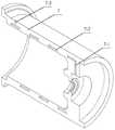
图5是本发明冷却水箱的三维结构示意图;Fig. 5 is the three-dimensional structure schematic diagram of the cooling water tank of the present invention;
图6为本发明冷却水箱另一角度的三维结构示意图。FIG. 6 is a schematic view of the three-dimensional structure of the cooling water tank of the present invention from another angle.
图中:In the picture:
1—泵壳、2—前护板、3—叶轮、4—后护板、5—蜗壳、6—前端盖、7—电机壳体、7-1—进水孔、7-2—螺旋水道、7-3—出水孔、8—轴、9—转子铁芯、10—永磁体、11—定子铁芯、12—绕组、13—后端盖、14—腔体封盖、15—嵌入式腔体、15-1—小孔、16—小叶轮、17—进水管、18—出水管、19—前端盖密封圈、20—毛毡密封圈Ⅰ、21—轴端密封圈Ⅰ、22—轴承Ⅰ、23—轴承Ⅱ、24—轴端密封圈Ⅱ、25—毛毡密封圈Ⅱ、26—后端盖密封圈Ⅰ、27—后端盖密封圈Ⅱ、28—底座、29—冷却水箱、29-1—风扇、29-2—分隔板Ⅰ、29-3—分隔板Ⅱ。1—Pump casing, 2—Front guard, 3—Impeller, 4—Rear guard, 5—Volute, 6—Front cover, 7—Motor housing, 7-1—Water inlet, 7-2— Spiral water channel, 7-3—water outlet, 8—shaft, 9—rotor iron core, 10—permanent magnet, 11—stator iron core, 12—winding, 13—rear end cover, 14—cavity cover, 15— Embedded cavity, 15-1—small hole, 16—small impeller, 17—water inlet pipe, 18—water outlet pipe, 19—front cover sealing ring, 20—felt sealing ring I, 21—shaft end sealing ring I, 22 —Bearing I, 23—Bearing II, 24—Shaft end seal II, 25—Felt seal II, 26—Rear end cover seal I, 27—Rear end cover seal II, 28—Base, 29—Cooling water tank , 29-1—fan, 29-2—partition plate I, 29-3—partition plate II.
具体实施方式Detailed ways
以下结合附图对本发明的特征和原理进行详细说明,所举实施例仅用于解释本发明,并非以此限定本发明的保护范围。The features and principles of the present invention will be described in detail below with reference to the accompanying drawings. The examples are only used to explain the present invention, and are not intended to limit the protection scope of the present invention.
如图1至图6所示,一种具有水冷循环结构的永磁直驱渣浆泵,包括泵体、永磁同步电机、进水管17、出水管18、底座28和冷却水箱29。As shown in FIGS. 1 to 6 , a permanent magnet direct drive slurry pump with a water cooling circulation structure includes a pump body, a permanent magnet synchronous motor, a
如图1所示,其中,泵体和永磁同步电机通过轴8连接,并固定安装在底座28上。永磁同步电机与渣浆泵为一体式结构,两者共用一根轴,省去了联轴器和减速器,从而避免连续工作时高温对联轴器、轴承箱造成的不良影响,大幅提高传动效率,降低了故障率。As shown in FIG. 1 , the pump body and the permanent magnet synchronous motor are connected through the
泵体包括泵壳1、前护板2、叶轮3、后护板4和蜗壳5。泵壳1内部设有蜗壳5,所述蜗壳5内部设有叶轮3。叶轮3前后两侧分别设有前护板2和后护板4。The pump body includes a pump casing 1 , a
永磁同步电机包括前端盖6、电机壳体7、轴8、内置冷却液驱动装置和后端盖13。电机壳体7与泵壳1通过螺栓紧固连接。电机壳体7左端设有前端盖6,前端盖6通过螺钉与电机壳体7连接固定。前端盖6与泵壳之间设有前端盖密封圈19进行密封。轴8的左端通过轴承Ⅰ22安装在前端盖6内,轴8与前端盖6之间设有毛毡密封圈Ⅰ20和轴端密封圈Ⅰ21。轴8的右端通过轴承Ⅱ23安装在电机壳体7内,轴8与电机壳体7之间设有毛毡密封圈Ⅰ20和轴端密封圈Ⅰ21。轴8的最左端通过花键与叶轮3连接,以传递扭矩。轴8上设置有转子铁芯9和永磁体10。永磁体10的外围设有定子铁芯11。永磁体10外围设置有定子铁芯11及绕组12,并固定安装在电机壳体7内部。The permanent magnet synchronous motor includes a
如图2所示,电机壳体7内设有进水孔7-1、螺旋水道7-2以及出水孔7-3。电机壳体7内嵌入安装有内置冷却液驱动装置,包括腔体封盖14、嵌入式腔体15和小叶轮16。通过将冷却液驱动装置嵌入到电机壳体7是内部,避免了使用额外驱动装置。As shown in FIG. 2 , the
嵌入式腔体15与腔体封盖14通过螺钉连接固定,腔体封盖14通过螺钉与电机壳体7连接固定。嵌入式腔体15内部设有小叶轮16,所述小叶轮16通过平键与轴8的最右端连接,以传递扭矩。内置冷却液驱动装置中的小叶轮能够在一定程度上抵消渣浆工作过程中的轴向力,降低因轴向力造成的不利影响。The embedded
如图3、图4所示,嵌入式腔体15上端设置有小孔15-1,小孔15-1与进水孔7-1连通并且等径同轴。小孔15-1与进水孔7-1连通螺旋水道7-2和嵌入式腔体15内部。腔体封盖14右端设有后端盖13,后端盖13与电机壳体7通过螺钉固定连接。腔体封盖14与后端盖13之间设有两级密封圈,包括后端盖密封圈Ⅰ和后端盖密封圈Ⅱ。As shown in FIG. 3 and FIG. 4 , the upper end of the embedded
进水管17由冷却水箱29左端接出,并穿过后端盖13和腔体封盖14,与嵌入式腔体15内部连通。进水管17在管口处设有温度传感器。进水管18由电机壳体7上出水孔7-3接出,并由上端接入冷却水箱29内。The
如图5、图6所示,冷却水箱29内部设有分隔板Ⅰ29-2和分隔板Ⅱ29-3。分隔板Ⅰ29-2和分隔板Ⅱ29-3将冷却水箱29中冷却水流出端和流入端分隔开。冷却水箱29后端设有设置有两组风扇29-1,所述风扇29-1能够实现对出水管端的冷却水进行降温。冷却水箱后端风扇可以对冷却液进行降温,提高冷却液循环使用效率,有效节约资源。As shown in FIGS. 5 and 6 , the cooling
在渣浆泵工作过程中,温度较低的冷却水从冷却水箱29左端吸出,经进水管17流入嵌入式腔体15内部,再经过小孔15-1和进水孔7-1进入电机壳体7内的螺旋水道7-2,从出水孔7-3流入出水管18,最终流入冷却水箱29右端,完成整个冷却水的循环。当温度传感器检测到水温度过高时,冷却水箱29后端的两组风扇29-1会根据温度等级智能开启或停止,实现最佳冷却效果。During the operation of the slurry pump, the cooling water with lower temperature is sucked out from the left end of the cooling
上述实施例仅仅是对本发明的优选实施方式进行的描述,并非对本发明的范围进行限定,在不脱离本发明设计精神的前提下,本领域相关技术人员对本发明的各种变形和改进,均应扩入本发明权利要求书所确定的保护范围内。The above embodiments are only descriptions of the preferred embodiments of the present invention, and do not limit the scope of the present invention. On the premise of not departing from the design spirit of the present invention, various modifications and improvements of the present invention by those skilled in the art should be It is expanded into the protection scope determined by the claims of the present invention.
Claims (3)
Priority Applications (2)
| Application Number | Priority Date | Filing Date | Title |
|---|---|---|---|
| CN202010392407.9ACN111561453B (en) | 2020-05-11 | 2020-05-11 | Permanent magnet direct-drive slurry pump with water-cooling circulation structure |
| PCT/CN2020/106924WO2021227262A1 (en) | 2020-05-11 | 2020-08-05 | Permanent magnet direct drive slurry pump having water cooling circulation structure |
Applications Claiming Priority (1)
| Application Number | Priority Date | Filing Date | Title |
|---|---|---|---|
| CN202010392407.9ACN111561453B (en) | 2020-05-11 | 2020-05-11 | Permanent magnet direct-drive slurry pump with water-cooling circulation structure |
Publications (2)
| Publication Number | Publication Date |
|---|---|
| CN111561453A CN111561453A (en) | 2020-08-21 |
| CN111561453Btrue CN111561453B (en) | 2022-05-27 |
Family
ID=72070887
Family Applications (1)
| Application Number | Title | Priority Date | Filing Date |
|---|---|---|---|
| CN202010392407.9AActiveCN111561453B (en) | 2020-05-11 | 2020-05-11 | Permanent magnet direct-drive slurry pump with water-cooling circulation structure |
Country Status (2)
| Country | Link |
|---|---|
| CN (1) | CN111561453B (en) |
| WO (1) | WO2021227262A1 (en) |
Families Citing this family (8)
| Publication number | Priority date | Publication date | Assignee | Title |
|---|---|---|---|---|
| CN114567115B (en)* | 2022-03-16 | 2024-04-19 | 河南科技大学 | Hydraulic motor pump with forced flow heat dissipation function |
| CN114909299A (en)* | 2022-05-07 | 2022-08-16 | 安徽南方化工泵业有限公司 | A stainless steel high temperature magnetic pump |
| CN115822999A (en)* | 2022-12-17 | 2023-03-21 | 大庆特博科技发展有限公司 | Sealed cooling structure of high-speed turbine aeration fan |
| CN117013744B (en)* | 2023-08-17 | 2024-08-30 | 常州宝马前杨电机电器有限公司 | Strong heat dissipation reluctance type stepping motor |
| CN118462655B (en)* | 2024-05-29 | 2024-10-29 | 北京科德铭通科技有限责任公司 | Centrifugal pump radiating part and energy-saving centrifugal pump |
| CN118282132B (en)* | 2024-05-31 | 2024-09-03 | 江苏微特利电机股份有限公司 | High-efficient heat dissipation processing apparatus is used to PMSM |
| CN118630955B (en)* | 2024-06-04 | 2025-03-18 | 东营合瑞石油技术有限责任公司 | A flameproof variable frequency permanent magnet motor |
| CN120033912B (en)* | 2025-03-24 | 2025-08-08 | 山东博迈尔装备技术有限公司 | Energy-saving circulating water cooling structure of permanent magnet motor |
Citations (8)
| Publication number | Priority date | Publication date | Assignee | Title |
|---|---|---|---|---|
| CN2713186Y (en)* | 2004-06-26 | 2005-07-27 | 中国矿业大学 | Dreg slurry pump |
| CN102251991A (en)* | 2011-08-19 | 2011-11-23 | 江苏大学 | Axial force balance device and method for shield pump |
| CN204419677U (en)* | 2015-01-21 | 2015-06-24 | 徐州长龙能源科技有限公司 | A kind of Pulp pump sealing box structure |
| CN204961410U (en)* | 2015-09-17 | 2016-01-13 | 四川达竹煤电(集团)有限责任公司石板选煤发电厂 | Sediment stuff pump with cooling water is from circulating device |
| CN108518347A (en)* | 2018-06-11 | 2018-09-11 | 杭州大路实业有限公司 | A kind of integral shaft synchronizes canned motor pump to suspension permanent magnet |
| CN109026719A (en)* | 2018-07-24 | 2018-12-18 | 高邮市高农机械配件有限公司 | A kind of electronic water pump for automobile |
| CN109812422A (en)* | 2019-01-11 | 2019-05-28 | 江苏泰丰泵业有限公司 | A bedroom cold water pump |
| CN110725802A (en)* | 2019-11-20 | 2020-01-24 | 上海佰诺泵阀有限公司 | Integrated magnetic pump in impeller |
Family Cites Families (7)
| Publication number | Priority date | Publication date | Assignee | Title |
|---|---|---|---|---|
| DE102014106456A1 (en)* | 2014-05-08 | 2015-11-12 | Dr. Ing. H.C. F. Porsche Aktiengesellschaft | Electric machine for use in the automotive sector with a cylindrical housing arrangement |
| CN204046357U (en)* | 2014-07-19 | 2014-12-24 | 李东文 | A kind of electric automobile water-cooled machine |
| CN105351212A (en)* | 2015-10-30 | 2016-02-24 | 耐驰泵阀科技(天津)有限公司 | Water pump with cooling function |
| CN105909532A (en)* | 2016-07-12 | 2016-08-31 | 合肥新沪屏蔽泵有限公司 | Water-cooled shield pump |
| FR3060896B1 (en)* | 2016-12-20 | 2019-11-15 | Valeo Systemes De Controle Moteur | ELECTRIC COMPRESSOR WITH COOLING CIRCUIT |
| CN206917863U (en)* | 2017-07-26 | 2018-01-23 | 刘国云 | A kind of horizontal pipeline centrifugal pump |
| US10272767B1 (en)* | 2018-03-23 | 2019-04-30 | Sf Motors, Inc. | Dual loop liquid cooling of integrated electric drivetrain |
- 2020
- 2020-05-11CNCN202010392407.9Apatent/CN111561453B/enactiveActive
- 2020-08-05WOPCT/CN2020/106924patent/WO2021227262A1/ennot_activeCeased
Patent Citations (8)
| Publication number | Priority date | Publication date | Assignee | Title |
|---|---|---|---|---|
| CN2713186Y (en)* | 2004-06-26 | 2005-07-27 | 中国矿业大学 | Dreg slurry pump |
| CN102251991A (en)* | 2011-08-19 | 2011-11-23 | 江苏大学 | Axial force balance device and method for shield pump |
| CN204419677U (en)* | 2015-01-21 | 2015-06-24 | 徐州长龙能源科技有限公司 | A kind of Pulp pump sealing box structure |
| CN204961410U (en)* | 2015-09-17 | 2016-01-13 | 四川达竹煤电(集团)有限责任公司石板选煤发电厂 | Sediment stuff pump with cooling water is from circulating device |
| CN108518347A (en)* | 2018-06-11 | 2018-09-11 | 杭州大路实业有限公司 | A kind of integral shaft synchronizes canned motor pump to suspension permanent magnet |
| CN109026719A (en)* | 2018-07-24 | 2018-12-18 | 高邮市高农机械配件有限公司 | A kind of electronic water pump for automobile |
| CN109812422A (en)* | 2019-01-11 | 2019-05-28 | 江苏泰丰泵业有限公司 | A bedroom cold water pump |
| CN110725802A (en)* | 2019-11-20 | 2020-01-24 | 上海佰诺泵阀有限公司 | Integrated magnetic pump in impeller |
Also Published As
| Publication number | Publication date |
|---|---|
| WO2021227262A1 (en) | 2021-11-18 |
| CN111561453A (en) | 2020-08-21 |
Similar Documents
| Publication | Publication Date | Title |
|---|---|---|
| CN111561453B (en) | Permanent magnet direct-drive slurry pump with water-cooling circulation structure | |
| CN110566470A (en) | High-efficient low noise automotive electronics water pump | |
| CN211046642U (en) | Motor with double cooling channels | |
| CN112901533B (en) | A phase change cooling permanent magnet direct drive blower | |
| CN116398445A (en) | An integrated motor-driven centrifugal pump | |
| CN111969736A (en) | High-efficient water-cooling hydroelectric generator structure | |
| CN203879750U (en) | Shield pump conveying high temperature liquid | |
| CN110601448A (en) | Liquid cooling high power density position-free control PMSM motor | |
| CN211183643U (en) | Main shaft motor casing with water-cooling channel | |
| CN113217402A (en) | Water-cooling intelligent pump | |
| CN113107863A (en) | Water-cooling efficient multistage pump | |
| CN108953165A (en) | A kind of water cooling high-efficiency water pump | |
| CN201246314Y (en) | Direct connecting type high speed centrifugal air blower | |
| CN111342583A (en) | Novel adjustable rotor cooling system | |
| CN115664117B (en) | Liquid cooling device of double-stator permanent magnet direct drive motor | |
| CN217135286U (en) | Water cooling pump integrated motor | |
| CN114552852B (en) | Large-scale internal-external mixed double-air-cooling and water-cooling permanent magnet synchronous motor | |
| CN113482939B (en) | High-efficiency water-cooling outer rotor type permanent magnet intelligent water pump with integrated controller | |
| CN215908071U (en) | Submersible wet type full tubular pump without shaft structure | |
| CN110671335B (en) | A counter-rotating structure multistage high temperature pump | |
| CN201478947U (en) | Low-noise water-cooled motor for water pumps | |
| CN115370594A (en) | Self-suction cooling type air floatation direct-drive centrifugal blower and working method | |
| CN212463019U (en) | A permanent magnet synchronous workpiece shaft of a bearing grinder | |
| CN221074714U (en) | Motor shaft for water pump motor | |
| CN111755214A (en) | Transformer magnetic leakage driving type heat dissipation oil tank |
Legal Events
| Date | Code | Title | Description |
|---|---|---|---|
| PB01 | Publication | ||
| PB01 | Publication | ||
| SE01 | Entry into force of request for substantive examination | ||
| SE01 | Entry into force of request for substantive examination | ||
| GR01 | Patent grant | ||
| GR01 | Patent grant |