CN111555633A - A DC transformer for new energy DC grid connection and its control method - Google Patents
A DC transformer for new energy DC grid connection and its control methodDownload PDFInfo
- Publication number
- CN111555633A CN111555633ACN202010457172.7ACN202010457172ACN111555633ACN 111555633 ACN111555633 ACN 111555633ACN 202010457172 ACN202010457172 ACN 202010457172ACN 111555633 ACN111555633 ACN 111555633A
- Authority
- CN
- China
- Prior art keywords
- diode
- switch
- transformer
- voltage
- zero
- Prior art date
- Legal status (The legal status is an assumption and is not a legal conclusion. Google has not performed a legal analysis and makes no representation as to the accuracy of the status listed.)
- Granted
Links
- 238000000034methodMethods0.000titleclaimsabstractdescription17
- 239000003990capacitorSubstances0.000claimsdescription97
- 230000007423decreaseEffects0.000claimsdescription11
- 230000005284excitationEffects0.000claimsdescription9
- 230000002457bidirectional effectEffects0.000claimsdescription5
- 230000000295complement effectEffects0.000claimsdescription5
- 230000010363phase shiftEffects0.000claimsdescription3
- 230000033228biological regulationEffects0.000abstractdescription3
- 238000006243chemical reactionMethods0.000abstractdescription2
- 238000010586diagramMethods0.000description14
- 238000009795derivationMethods0.000description4
- 230000005540biological transmissionEffects0.000description2
- 230000004048modificationEffects0.000description2
- 238000012986modificationMethods0.000description2
- 238000011160researchMethods0.000description2
- 230000007812deficiencyEffects0.000description1
- 230000005611electricityEffects0.000description1
Images


Classifications
- H—ELECTRICITY
- H02—GENERATION; CONVERSION OR DISTRIBUTION OF ELECTRIC POWER
- H02M—APPARATUS FOR CONVERSION BETWEEN AC AND AC, BETWEEN AC AND DC, OR BETWEEN DC AND DC, AND FOR USE WITH MAINS OR SIMILAR POWER SUPPLY SYSTEMS; CONVERSION OF DC OR AC INPUT POWER INTO SURGE OUTPUT POWER; CONTROL OR REGULATION THEREOF
- H02M3/00—Conversion of DC power input into DC power output
- H02M3/22—Conversion of DC power input into DC power output with intermediate conversion into AC
- H02M3/24—Conversion of DC power input into DC power output with intermediate conversion into AC by static converters
- H02M3/28—Conversion of DC power input into DC power output with intermediate conversion into AC by static converters using discharge tubes with control electrode or semiconductor devices with control electrode to produce the intermediate AC
- H02M3/325—Conversion of DC power input into DC power output with intermediate conversion into AC by static converters using discharge tubes with control electrode or semiconductor devices with control electrode to produce the intermediate AC using devices of a triode or a transistor type requiring continuous application of a control signal
- H02M3/335—Conversion of DC power input into DC power output with intermediate conversion into AC by static converters using discharge tubes with control electrode or semiconductor devices with control electrode to produce the intermediate AC using devices of a triode or a transistor type requiring continuous application of a control signal using semiconductor devices only
- H02M3/3353—Conversion of DC power input into DC power output with intermediate conversion into AC by static converters using discharge tubes with control electrode or semiconductor devices with control electrode to produce the intermediate AC using devices of a triode or a transistor type requiring continuous application of a control signal using semiconductor devices only having at least two simultaneously operating switches on the input side, e.g. "double forward" or "double (switched) flyback" converter
- H—ELECTRICITY
- H02—GENERATION; CONVERSION OR DISTRIBUTION OF ELECTRIC POWER
- H02J—CIRCUIT ARRANGEMENTS OR SYSTEMS FOR SUPPLYING OR DISTRIBUTING ELECTRIC POWER; SYSTEMS FOR STORING ELECTRIC ENERGY
- H02J1/00—Circuit arrangements for DC mains or DC distribution networks
- H02J1/10—Parallel operation of DC sources
- H—ELECTRICITY
- H02—GENERATION; CONVERSION OR DISTRIBUTION OF ELECTRIC POWER
- H02M—APPARATUS FOR CONVERSION BETWEEN AC AND AC, BETWEEN AC AND DC, OR BETWEEN DC AND DC, AND FOR USE WITH MAINS OR SIMILAR POWER SUPPLY SYSTEMS; CONVERSION OF DC OR AC INPUT POWER INTO SURGE OUTPUT POWER; CONTROL OR REGULATION THEREOF
- H02M1/00—Details of apparatus for conversion
- H02M1/08—Circuits specially adapted for the generation of control voltages for semiconductor devices incorporated in static converters
- H02M1/083—Circuits specially adapted for the generation of control voltages for semiconductor devices incorporated in static converters for the ignition at the zero crossing of the voltage or the current
- H—ELECTRICITY
- H02—GENERATION; CONVERSION OR DISTRIBUTION OF ELECTRIC POWER
- H02M—APPARATUS FOR CONVERSION BETWEEN AC AND AC, BETWEEN AC AND DC, OR BETWEEN DC AND DC, AND FOR USE WITH MAINS OR SIMILAR POWER SUPPLY SYSTEMS; CONVERSION OF DC OR AC INPUT POWER INTO SURGE OUTPUT POWER; CONTROL OR REGULATION THEREOF
- H02M1/00—Details of apparatus for conversion
- H02M1/08—Circuits specially adapted for the generation of control voltages for semiconductor devices incorporated in static converters
- H02M1/088—Circuits specially adapted for the generation of control voltages for semiconductor devices incorporated in static converters for the simultaneous control of series or parallel connected semiconductor devices
- H—ELECTRICITY
- H02—GENERATION; CONVERSION OR DISTRIBUTION OF ELECTRIC POWER
- H02M—APPARATUS FOR CONVERSION BETWEEN AC AND AC, BETWEEN AC AND DC, OR BETWEEN DC AND DC, AND FOR USE WITH MAINS OR SIMILAR POWER SUPPLY SYSTEMS; CONVERSION OF DC OR AC INPUT POWER INTO SURGE OUTPUT POWER; CONTROL OR REGULATION THEREOF
- H02M3/00—Conversion of DC power input into DC power output
- H02M3/22—Conversion of DC power input into DC power output with intermediate conversion into AC
- H02M3/24—Conversion of DC power input into DC power output with intermediate conversion into AC by static converters
- H02M3/28—Conversion of DC power input into DC power output with intermediate conversion into AC by static converters using discharge tubes with control electrode or semiconductor devices with control electrode to produce the intermediate AC
- H02M3/325—Conversion of DC power input into DC power output with intermediate conversion into AC by static converters using discharge tubes with control electrode or semiconductor devices with control electrode to produce the intermediate AC using devices of a triode or a transistor type requiring continuous application of a control signal
- H02M3/335—Conversion of DC power input into DC power output with intermediate conversion into AC by static converters using discharge tubes with control electrode or semiconductor devices with control electrode to produce the intermediate AC using devices of a triode or a transistor type requiring continuous application of a control signal using semiconductor devices only
- H02M3/33569—Conversion of DC power input into DC power output with intermediate conversion into AC by static converters using discharge tubes with control electrode or semiconductor devices with control electrode to produce the intermediate AC using devices of a triode or a transistor type requiring continuous application of a control signal using semiconductor devices only having several active switching elements
- H02M3/33576—Conversion of DC power input into DC power output with intermediate conversion into AC by static converters using discharge tubes with control electrode or semiconductor devices with control electrode to produce the intermediate AC using devices of a triode or a transistor type requiring continuous application of a control signal using semiconductor devices only having several active switching elements having at least one active switching element at the secondary side of an isolation transformer
- H—ELECTRICITY
- H02—GENERATION; CONVERSION OR DISTRIBUTION OF ELECTRIC POWER
- H02J—CIRCUIT ARRANGEMENTS OR SYSTEMS FOR SUPPLYING OR DISTRIBUTING ELECTRIC POWER; SYSTEMS FOR STORING ELECTRIC ENERGY
- H02J2300/00—Systems for supplying or distributing electric power characterised by decentralized, dispersed, or local generation
- H02J2300/20—The dispersed energy generation being of renewable origin
- H—ELECTRICITY
- H02—GENERATION; CONVERSION OR DISTRIBUTION OF ELECTRIC POWER
- H02M—APPARATUS FOR CONVERSION BETWEEN AC AND AC, BETWEEN AC AND DC, OR BETWEEN DC AND DC, AND FOR USE WITH MAINS OR SIMILAR POWER SUPPLY SYSTEMS; CONVERSION OF DC OR AC INPUT POWER INTO SURGE OUTPUT POWER; CONTROL OR REGULATION THEREOF
- H02M1/00—Details of apparatus for conversion
- H02M1/0048—Circuits or arrangements for reducing losses
- H02M1/0054—Transistor switching losses
- H02M1/0058—Transistor switching losses by employing soft switching techniques, i.e. commutation of transistors when applied voltage is zero or when current flow is zero
- Y—GENERAL TAGGING OF NEW TECHNOLOGICAL DEVELOPMENTS; GENERAL TAGGING OF CROSS-SECTIONAL TECHNOLOGIES SPANNING OVER SEVERAL SECTIONS OF THE IPC; TECHNICAL SUBJECTS COVERED BY FORMER USPC CROSS-REFERENCE ART COLLECTIONS [XRACs] AND DIGESTS
- Y02—TECHNOLOGIES OR APPLICATIONS FOR MITIGATION OR ADAPTATION AGAINST CLIMATE CHANGE
- Y02B—CLIMATE CHANGE MITIGATION TECHNOLOGIES RELATED TO BUILDINGS, e.g. HOUSING, HOUSE APPLIANCES OR RELATED END-USER APPLICATIONS
- Y02B70/00—Technologies for an efficient end-user side electric power management and consumption
- Y02B70/10—Technologies improving the efficiency by using switched-mode power supplies [SMPS], i.e. efficient power electronics conversion e.g. power factor correction or reduction of losses in power supplies or efficient standby modes
- Y—GENERAL TAGGING OF NEW TECHNOLOGICAL DEVELOPMENTS; GENERAL TAGGING OF CROSS-SECTIONAL TECHNOLOGIES SPANNING OVER SEVERAL SECTIONS OF THE IPC; TECHNICAL SUBJECTS COVERED BY FORMER USPC CROSS-REFERENCE ART COLLECTIONS [XRACs] AND DIGESTS
- Y02—TECHNOLOGIES OR APPLICATIONS FOR MITIGATION OR ADAPTATION AGAINST CLIMATE CHANGE
- Y02E—REDUCTION OF GREENHOUSE GAS [GHG] EMISSIONS, RELATED TO ENERGY GENERATION, TRANSMISSION OR DISTRIBUTION
- Y02E10/00—Energy generation through renewable energy sources
- Y02E10/50—Photovoltaic [PV] energy
- Y02E10/56—Power conversion systems, e.g. maximum power point trackers
Landscapes
- Engineering & Computer Science (AREA)
- Power Engineering (AREA)
- Inverter Devices (AREA)
Abstract
Description
Translated fromChinese技术领域technical field
本发明属于电力电子技术领域,涉及一种用于新能源直流并网的调频可控型直流变压器拓扑及其控制方法,适用于中压直流大功率场合。The invention belongs to the technical field of power electronics, and relates to a frequency-modulated and controllable DC transformer topology and a control method thereof for new energy DC grid connection, which are suitable for medium-voltage DC and high-power occasions.
背景技术Background technique
随着不可再生能源的消耗,能源紧缺等问题的产生,太阳能和风能等可再生能源成为研究热点,随着光伏电厂和风电场的不断建设,新能源汇集问题越来越受到重视。中压直流汇集系统因其可降低汇集的线路损耗,因此亟需直流升压变压器将风机或者光伏发出的低压电升压至中压,以提高整体的效率以及运行性能。其中,谐振型直流变压器因其优越的软开关特性,且可通过调节开关频率调节输出功率而受到广泛关注。针对用于新能源直流并网的调频可控型直流变压器,近年来已出现了一些研究,但现有的新能源直流并网的调频可控型直流变压器的电路拓扑方案中,仍然存在几个主要问题:如采用的变频控制导致在宽输出范围内开关频率发生较大变化,使得开关损耗、变压器体积增加,设计难度增大;同时,当电压变化较宽时无法实现软开关。因此有必要提出一种可有效降低开关损耗、减小变压器体积的用于新能源直流并网的调频可控型直流变压器拓扑。With the consumption of non-renewable energy and the emergence of energy shortage and other problems, renewable energy such as solar energy and wind energy has become a research hotspot. Because the medium voltage DC collection system can reduce the line loss of the collection, a DC step-up transformer is urgently needed to boost the low-voltage electricity generated by the fan or photovoltaic to medium voltage, so as to improve the overall efficiency and operation performance. Among them, the resonant DC transformer has received extensive attention due to its superior soft switching characteristics and the ability to adjust the output power by adjusting the switching frequency. In recent years, there have been some researches on frequency-modulated controllable DC transformers for new energy DC grid-connected frequency-modulation controllable DC transformers. Main problems: For example, the use of variable frequency control leads to a large change in the switching frequency in a wide output range, which increases the switching loss, the volume of the transformer, and the design difficulty; at the same time, soft switching cannot be achieved when the voltage changes widely. Therefore, it is necessary to propose a frequency-modulated and controllable DC transformer topology that can effectively reduce the switching loss and reduce the volume of the transformer for new energy DC grid connection.
发明内容SUMMARY OF THE INVENTION
本发明针对现有技术存在的不足,提供了一种用于新能源直流并网的直流变压器及其控制方法。本发明中,每个功率模块采用调频控制,实现对功率和输出电压的调节,本发明的直流变压器可以在较宽输出电压范围内实现全负荷范围内的软开关;同时调频过程加在变压器上的正负电压脉宽时间固定,可有效降低变压器工作磁密,进而降低变压器体积。Aiming at the deficiencies in the prior art, the present invention provides a DC transformer for new energy DC grid connection and a control method thereof. In the present invention, each power module adopts frequency modulation control to realize the regulation of power and output voltage. The DC transformer of the present invention can realize soft switching within the full load range within a wide output voltage range; at the same time, the frequency modulation process is added to the transformer. The positive and negative voltage pulse width time is fixed, which can effectively reduce the working magnetic density of the transformer, thereby reducing the volume of the transformer.
本发明的目的是通过以下技术方案实现的:The purpose of this invention is to realize through the following technical solutions:
一种用于新能源直流并网的直流变压器,由N个结构相同的功率模块构成,其中:A DC transformer for new energy DC grid connection is composed of N power modules with the same structure, wherein:
N个功率模块低压侧并联后的直流输入端正极与低压直流母线的正极相连,直流输入端负极与低压直流母线的负极相连;The positive poles of the DC input terminals of the low-voltage sides of the N power modules connected in parallel are connected to the positive poles of the low-voltage DC bus bars, and the negative poles of the DC input terminals are connected to the negative poles of the low-voltage DC bus bars;
N个功率模块中压侧串联后的直流输出端正极与中压直流电网的正极相连,直流输出端负极与中压直流电网的负极相连;The positive poles of the DC output terminals after the medium voltage sides of the N power modules are connected in series are connected to the positive poles of the medium voltage DC grid, and the negative poles of the DC output terminals are connected to the negative poles of the medium voltage DC grid;
功率模块包括H桥、三电平整流桥、输入滤波电容Ci、第一输出滤波电容Co1、第二输出滤波电容Co2、变压器原边、变压器副边、谐振电感Lr、第一谐振电容Cr1和第二谐振电容Cr2;The power module includes an H bridge, a three-level rectifier bridge, an input filter capacitor Ci , a first output filter capacitor Co1 , a second output filter capacitor Co2 , the primary side of the transformer, the secondary side of the transformer, the resonant inductor Lr , the first resonance a capacitor Cr1 and a second resonant capacitor Cr2 ;
H桥包括第一开关管S1、第二开关管S2、第三开关管S3和第四开关管S4;The H bridge includes a first switch S1 , a second switch S2 , a third switch S3 and a fourth switch S4 ;
三电平整流桥包括第一二极管D1、第二二极管D2、第三二极管D3、第四二极管D4、第五二极管Dc1和第六二极管Dc2;The three-level rectifier bridge includes a first diode D1 , a second diode D2 , a third diode D3 , a fourth diode D4 , a fifth diode Dc1 and a sixth diode tube Dc2 ;
第一开关管S1的发射极与第二开关管S2的集电极相连构成第一桥臂,第三开关管S3的发射极与第四开关管S4的集电极构成第二桥臂;The emitter of thefirst switch S1 is connected with the collector of thesecond switch S2 to form the first bridge arm, and the emitter of thethird switch S3 and the collector of thefourth switch S4 form the second bridge arm ;
输入端的正极经输入滤波电容Ci正极分别连接第一开关管S1和第三开关管S3的集电极,输入端的负极经输入滤波电容Ci负极分别连接第二开关管S2和第四开关管S4的发射极,输入滤波电容Ci两端构成直流输入端;The positive pole of the input terminal is respectively connected to the collectors of thefirst switch tube S1 and thethird switch tube S3 via the input filter capacitor Ci , and the negative pole of the input terminal is connected to thesecond switch tube S2 and the fourth switch tube S2 and the fourth switch tube S2 respectively via the negative pole of the input filter capacitor Ci .The emitter of the switch tube S4, the two ends of the input filter capacitor Ci constitute a DC input terminal;
变压器的原边同名端连接第一开关管S1与第二开关管S2的中间节点,另一端连接第三开关管S3与第四开关管S4的中间节点;The primary end of the transformer with the same name is connected to the intermediate node of thefirst switch S1 and thesecond switch S2, and the other end is connected to the intermediate node of thethird switch S3 and thefourth switch S4;
输出端的正极经第一输出滤波电容Co1正极与第一二极管D1的阴极相连,第一二极管D1的阳极分别与第二二极管D2的阴极和第五二极管Dc1的阴极相连,第二二极管D2的阳极与第三二极管D3的阴极相连,第三二极管D3的阳极分别与第四二极管D4的阴极和第六二极管Dc2的阳极相连,第五二极管Dc1的阳极与第六二极管Dc2的阴极相连;The anode of the output terminal is connected to the cathode of the first diode D1 through the anode of thefirst output filter capacitor Co1 , and the anode of thefirst diode D1 is respectively connected to the cathode of thesecond diode D2 and the fifth diode The cathode of Dc1 is connected, the anode of thesecond diode D2 is connected to the cathode of the third diodeD3 , the anode of the third diodeD3 is connected to the cathode of thefourth diode D4 and the sixth The anode of the diode Dc2 is connected, and the anode of the fifth diode Dc1 is connected to the cathode of the sixth diode Dc2 ;
第一谐振电容Cr1的一端与第五二极管Dc1的阴极相连,另一端与第五二极管Dc1的阳极相连;One end of the first resonance capacitor Cr1 is connected to the cathode of the fifth diode Dc1 , and the other end is connected to the anode of the fifth diode Dc1 ;
第二谐振电容Cr2的一端与第六二极管Dc2的阴极相连,另一端与第六二极管Dc2的阳极相连;One end of the second resonance capacitor Cr2 is connected to the cathode of the sixth diode Dc2 , and the other end is connected to the anode of the sixth diode Dc2 ;
变压器的副边同名端经谐振电感Lr连接第一谐振电容Cr1与第二谐振电容Cr2的中间节点,另一端连接第二二极管D2与第三二极管D3的中间节点;The secondary side of the transformer with the same name is connected to the intermediate node of the first resonant capacitor Cr1 and the second resonant capacitor Cr2 via the resonant inductor Lr , and the other end is connected to the intermediate node of the second diode D2 and the third diode D3 ;
第一输出滤波电容Co1与第二输出滤波电容Co2串联后的中间节点与第二二极管D2和第三二极管D3的中间节点相连,第一输出滤波电容Co1与第二输出滤波电容Co2串联后的两端构成直流输出端。The intermediate node of the first output filter capacitor Co1 and the second output filter capacitor Co2 connected in series is connected to the intermediate node of the second diode D2 and the third diode D3 , and the first output filter capacitor Co1 is connected to the second diode D 2 and the intermediate node of the third diode D 3 . The two ends of the two output filter capacitors Co2 connected in series constitute a DC output end.
一种上述用于新能源直流并网的直流变压器的控制方法,第一开关管S1和第二开关管S2以50%占空比互补运行,第三开关管S3与第四开关管S4以50%占空比互补运行;通过调节开关频率可调节传输功率。第一桥臂与第二桥臂之间移相时间固定,使得H桥产生脉宽时间固定的三电平波形。设一个控制周期为T,时间为t0≤t≤t12,其中t0≤t≤t6为前半周期,t7≤t≤t12为后半周期,其中:A control method of the above-mentioned DC transformer for new energy DC grid connection, thefirst switch S1 and thesecond switch S2 are operated complementary with a 50% duty cycle, thethird switch S3 and the fourth switch S3 S4 operates complementary at 50% duty cycle; the transmission power can be adjusted by adjusting the switching frequency. The phase shift time between the first bridge arm and the second bridge arm is fixed, so that the H bridge generates a three-level waveform with a fixed pulse width and time. Let a control period be T and time be t0 ≤t≤t12 , where t0 ≤t≤t6 is the first half period, t7 ≤t≤t12 is the second half period, where:
一、前半周期First, the first half cycle
具体控制方法如下:The specific control method is as follows:
初始时刻t0:t0为一个控制周期的起点,此时变压器副边电流即流经谐振电感Lr的值为零,变压器原边电流即流经第一开关管S1和第四开关管S4值为负,此时开通第四开关管S4为零电压开通,第一谐振电容Cr1电压和第二谐振电容Cr2电压分别等于第二输出滤波电容Co2两端电压Uo/2和零;Initial time t0 : t0 is the starting point of a control cycle. At this time, the value of the secondary current of the transformer flowing through the resonant inductor Lr is zero, and the current of the primary side of the transformer flowing through the first switch tube S1 and the fourth switch tube The value of S4 is negative, and thefourth switch S4 isturned on at zero voltage at this time. The voltage of the first resonant capacitor Cr1 and the voltage of the secondresonant capacitor Cr2 are respectively equal to the voltage Uo / 2 and zero;
第一开关模态:t0≤t≤t1,t0时刻第一开关管S1和第四开关管S4处于导通状态,第二开关管S2和第三开关管S3处于关断状态,第一二极管D1与第三二极管D3导通,谐振电感Lr与第一谐振电容Cr1和第二谐振电容Cr2发生谐振,变压器副边电流iLr的值从零开始正弦上升,第一谐振电容Cr1电压uCr1从Uo/2逐渐降至零,第二谐振电容Cr2电压uCr2从零逐渐升至Uo/2;The first switching mode: t0 ≤ t ≤ t1 , at time t0 thefirst switch S1 and thefourth switch S4 are in an on state, and thesecond switch S2 and thethird switch S3 are in an off state In the off state, thefirst diode D1 and the third diodeD3 are turned on, the resonant inductor Lr resonates with the first resonant capacitor Cr1 and the second resonant capacitor Cr2 , and the value of the transformer secondary current iLr The sine rises from zero, the voltage uCr1 of the first resonant capacitor Cr1 gradually decreases from Uo /2 to zero, and the voltage uCr2 of the second resonant capacitor Cr2 gradually increases from zero to Uo /2;
第二开关模态:t1≤t≤t2,t1时刻,由于第五二极管Dc1和第六二极管Dc2的存在,第一谐振电容Cr1电压和第二谐振电容Cr2电压分别被钳位到零和Uo/2,第五二极管Dc1导通,此时变压器原边电流ip的值和变压器副边电流iLr的值线性下降;The second switching mode: t1 ≤t≤t2 , at time t1 , due to the existence of the fifth diode Dc1 and the sixth diode Dc2 , the voltage of the first resonant capacitor Cr1 and the voltage of the second resonant capacitor C The voltage ofr2 is clamped to zero and Uo /2 respectively, and the fifth diode Dc1 is turned on. At this time, the value of the primary current ip of the transformer and the value of the secondary current iLr of the transformer decrease linearly;
第三开关模态:t2≤t≤t3,t2时刻,变压器副边电流iLr的值线性下降至零,中压侧二极管实现了零电流关断;The third switching mode: t2 ≤ t ≤ t3 , at time t2 , the value of the transformer secondary side current iLr linearly decreases to zero, and the medium-voltage side diode realizes zero-current shutdown;
第四开关模态:t3≤t≤t5,t3时刻,第一开关管S1关断,关断电流为幅值很小的激磁电流,近似为零电流关断;第一开关管S1关断后变压器原边电流ip流经第二开关管S2的反并联二极管,所以t4时刻第二开关管S2的开通为零电压开通,H桥输出电压up作用在变压器原边的值为零,原边电流ip等于激磁电流维持不变;The fourth switching mode: t3 ≤ t ≤ t5 , at time t3 , the first switch tube S1 is turned off, the turn-off current is an excitation current with a small amplitude, and is turned off at approximately zero current; the first
第五开关模态:t5≤t≤t6,t5时刻第四开关管S4关断,其关断电流也为幅值很小的激磁电流,所以也实现了零电流关断;第四开关管S4关断后变压器原边电流ip经第三开关管S3的反并联二极管续流,所以t6时刻第三开关管S3的开通为零电压开通;t6是前半个控制周期的终点,也是后半个控制周期的起点;The fifth switching mode: t5 ≤ t ≤ t6 , the fourth switch tube S4 is turned off at time t5 , and its turn-off current is also an excitation current with a small amplitude, so zero-current turn-off is also realized; After thefour switches S4 are turned off, the primary current ip of the transformer is freewheeling through the anti-parallel diode of thethird switch S3, so thethird switch S3 is turnedon at zero voltage at time t6; t6 is the first half The end of the control cycle is also the starting point of the second half of the control cycle;
二、后半周期Second, the second half of the cycle
后半周期的控制周期波形与前半周期的控制周期对称,后半周期的具体控制方法如下:The control cycle waveform of the second half cycle is symmetrical with the control cycle of the first half cycle. The specific control method of the second half cycle is as follows:
时刻t6:t6为后半控制周期的起点,此时变压器副边电流即流经谐振电感Lr的值为零,变压器原边电流为激磁电流且流经第二开关管S2和第三开关管S3的反并联二极管,此时开通第三开关管S3为零电压开通,第一谐振电容Cr1电压和第二谐振电容Cr2电压分别等于零和第一输出滤波电容Co1两端电压Uo/2;Time t6 : t6 is the starting point of the second half of the control cycle. At this time, the value of the secondary current of the transformer that flows through the resonant inductance Lr is zero, and the current of the primary side of the transformer is the excitation current and flows through the second switch tube S2 and the first The anti-parallel diode of thethree -switch S3 is turned on at this time, and thethird switch S3 is turned on at zero voltage. The voltage of the first resonant capacitor Cr1 and the voltage of the second resonant capacitor Cr2 are equal to zero and the first output filter capacitor Co1 respectively. Terminal voltage Uo /2;
第六开关模态:t6≤t≤t7,t6时刻第二开关管S2和第三开关管S3处于导通状态,第一开关管S1和第四开关管S4处于关断状态,第二二极管D2与第四二极管D4导通,谐振电感Lr与第一谐振电容Cr1和第二谐振电容Cr2发生谐振,变压器副边电流iLr的值从零开始正弦向负值变化。第一谐振电容Cr1电压uCr1从零逐渐升至Uo/2,第二谐振电容Cr2电压uCr2从Uo/2逐渐降至零;The sixth switching mode: t6 ≤ t ≤ t7 , at time t6 thesecond switch S2 and thethird switch S3 are in an on state, and thefirst switch S1 and thefourth switch S4 are in an off state In the off state, thesecond diode D2 and thefourth diode D4 are turned on, the resonant inductor Lr resonates with the first resonant capacitor Cr1 and the second resonant capacitor Cr2 , and the value of the transformer secondary current iLr Sinusoidal change from zero to negative values. The voltage uCr1 of the first resonant capacitor Cr1 gradually increases from zero to Uo /2, and the voltage uCr2 of the second resonant capacitor Cr2 gradually decreases from Uo /2 to zero;
第七开关模态:t7≤t≤t8,t7时刻,由于第五二极管Dc1和第六二极管Dc2的存在,第一谐振电容Cr1电压和第二谐振电容Cr2电压被分别钳位到Uo/2和零,第六二极管Dc2导通,此时变压器原边电流ip的值和变压器副边电流iLr的值线性上升;The seventh switching mode: t7 ≤t≤t8 , at time t7 , due to the existence of the fifth diode Dc1 and the sixth diode Dc2 , the voltage of the first resonant capacitor Cr1 and the voltage of the second resonant capacitor C The voltage ofr2 is clamped to Uo /2 and zero respectively, the sixth diode Dc2 is turned on, at this time, the value of the transformer primary current ip and the transformer secondary current iLr increase linearly;
第八开关模态:t8≤t≤t9,t8时刻,变压器副边电流iLr的值线性上升至零,中压侧二极管实现了零电流关断;Eighth switching mode: t8 ≤t ≤ t9 , at time t8 , the value of the transformer secondary side current iLr linearly rises to zero, and the medium-voltage side diode realizes zero-current turn-off;
第九开关模态:t9≤t≤t11,t9时刻,第二开关管S2关断,关断电流为幅值很小的激磁电流,近似为零电流关断;第二开关管S2关断后变压器原边电流ip流经第一开关管S1的反并联二极管,所以t10时刻,第一开关管S1的开通为零电压开通,H桥输出电压up作用在变压器原边的值为零;The ninth switching mode: t9 ≤ t ≤ t11 , at time t9 , the second switch tube S2 is turned off, the turn-off current is an excitation current with a small amplitude, and is turned off at approximately zero current; the second switch tube S 2 is turned off; After S2 is turned off, the primary currentip of the transformer flows through the anti- parallel diode of thefirst switch S1, so at time t10, thefirst switch S1 is turnedon at zero voltage, and the H-bridge output voltage up acts on The value on the primary side of the transformer is zero;
第十开关模态:t11≤t≤t12,t51时刻第三开关管S3关断,其关断电流也为幅值很小的激磁电流,所以也实现了零电流关断;第三开关管S3关断后变压器原边电流ip经第四开关管S4的反并联二极管续流,所以t12时刻第四开关管S4的开通为零电压开通;t12是后半个控制周期的终点,也是下一控制周期的起点。The tenth switching mode: t11 ≤ t ≤ t12 , thethird switch S3 is turned off at time t51 , and its turn-off current is also an excitation current with a small amplitude, so zero-current turn-off is also realized; After thethree switches S3 are turned off, the primary current ip of the transformer is freewheeling through the anti-parallel diode of thefourth switch S4, so thefourth switch S4 is turned on at zero voltage at timet12 ;t12 is the second half The end of a control cycle is also the start of the next control cycle.
相比于现有技术,本发明具有如下优点:Compared with the prior art, the present invention has the following advantages:
与现有调频可控型直流变压器相比,本发明的直流变压器可以在较宽输出电压范围内实现全负荷范围内的软开关,同时调频过程正负电压脉宽时间固定,控制方法简单,且可有效降低变压器工作磁密,进而降低变压器体积。对于相同输出电压等级,本发明的直流变压器可有效降低中压侧二极管的电压应力,可采用更低电压等级的二极管,降低成本。所以本发明的直流变压器具有体积小、效率高、成本低的特点,非常适用于新能源直流并网。Compared with the existing frequency-modulating controllable DC transformer, the DC transformer of the present invention can realize soft switching within the full-load range within a wider output voltage range, and meanwhile, the positive and negative voltage pulse width times are fixed in the frequency-modulating process, the control method is simple, and the control method is simple. It can effectively reduce the working magnetic density of the transformer, thereby reducing the volume of the transformer. For the same output voltage level, the DC transformer of the present invention can effectively reduce the voltage stress of the diode on the medium voltage side, and a diode with a lower voltage level can be used to reduce the cost. Therefore, the DC transformer of the present invention has the characteristics of small size, high efficiency and low cost, and is very suitable for new energy DC grid connection.
附图说明Description of drawings
图1为本发明提出的新能源直流并网的调频可控型直流变压器的整体示意图;Fig. 1 is the overall schematic diagram of the frequency modulation controllable DC transformer of new energy DC grid-connected proposed by the present invention;
图2为本发明提出的功率模块拓扑结构示意图;2 is a schematic diagram of a topology structure of a power module proposed by the present invention;
图3为本发明提出的功率模块典型驱动和电压电流波形;Fig. 3 is the typical drive and voltage and current waveforms of the power module proposed by the present invention;
图4为功率模块工作在第一开关模态的电流通路图;FIG. 4 is a current path diagram of the power module operating in the first switching mode;
图5为功率模块工作在第二开关模态的电流通路图;FIG. 5 is a current path diagram of the power module operating in the second switching mode;
图6为功率模块工作在第三开关模态的电流通路图;FIG. 6 is a current path diagram of the power module operating in the third switching mode;
图7为功率模块工作在第四开关模态的电流通路图;FIG. 7 is a current path diagram of the power module operating in the fourth switching mode;
图8为功率模块工作在第五开关模态的电流通路图;FIG. 8 is a current path diagram of the power module operating in the fifth switching mode;
图9为本发明的功率模块的双向拓扑结构示意图;9 is a schematic diagram of a bidirectional topology of the power module of the present invention;
图10为本发明的功率模块拓扑衍生示意图1;FIG. 10 is a schematic diagram 1 of the topology derivation of the power module of the present invention;
图11为本发明的功率模块拓扑衍生示意图2;FIG. 11 is a schematic diagram 2 of the topology derivation of the power module of the present invention;
图12为本发明的功率模块拓扑衍生示意图3。FIG. 12 is a schematic diagram 3 of the topology derivation of the power module of the present invention.
具体实施方式Detailed ways
下面结合附图对本发明的技术方案作进一步的说明,但并不局限于此,凡是对本发明技术方案进行修改或者等同替换,而不脱离本发明技术方案的精神和范围,均应涵盖在本发明的保护范围中。The technical solutions of the present invention will be further described below in conjunction with the accompanying drawings, but are not limited thereto. Any modification or equivalent replacement of the technical solutions of the present invention without departing from the spirit and scope of the technical solutions of the present invention shall be included in the present invention. within the scope of protection.
一种用于新能源直流并网的直流变压器,如图1所示,所述直流变压器由N个结构相同的功率模块构成,采用低压侧并联、中压侧串联结构,可实现直流电能变换,可实现单极结构或双极结构;N个功率模块低压侧并联后的直流输入端正极与低压直流母线的正极相连,直流输入端负极与低压直流母线的负极相连;N个功率模块中压侧串联后的直流输出端正极与中压直流电网的正极相连,直流输出端负极与中压直流电网的负极相连。A DC transformer for new energy DC grid connection, as shown in Figure 1, the DC transformer is composed of N power modules with the same structure, and adopts the low-voltage side in parallel and the medium-voltage side in series structure, which can realize DC power conversion, A unipolar structure or a bipolar structure can be realized; the positive pole of the DC input terminal after the low voltage side of the N power modules is connected in parallel is connected to the positive pole of the low voltage DC bus, and the negative pole of the DC input terminal is connected to the negative pole of the low voltage DC bus; the medium voltage side of the N power modules The positive pole of the DC output terminal connected in series is connected to the positive pole of the medium voltage DC grid, and the negative pole of the DC output terminal is connected to the negative pole of the medium voltage DC grid.
如图2所示,本发明提出的功率模块包括H桥、三电平整流桥、输入滤波电容Ci、第一输出滤波电容Co1、第二输出滤波电容Co2、变压器原边、变压器副边、谐振电感Lr、第一谐振电容Cr1和第二谐振电容Cr2。Ui为输入电压,Uo为输出电压。H桥包括第一开关管S1、第二开关管S2、第三开关管S3和第四开关管S4。三电平整流桥包括第一二极管D1、第二二极管D2、第三二极管D3、第四二极管D4、第五二极管Dc1和第六二极管Dc2。第一开关管S1的发射极与第二开关管S2的集电极相连构成第一桥臂,第三开关管S3的发射极与第四开关管S4的集电极构成第二桥臂;输入端的正极经输入滤波电容Ci正极分别连接第一开关管S1和第三开关管S3的集电极,输入端的负极经输入滤波电容Ci负极分别连接第二开关管S2和第四开关管S4的发射极,输入滤波电容Ci两端构成直流输入端;变压器的原边同名端连接第一开关管S1与第二开关管S2的中间节点,另一端连接第三开关管S3与第四开关管S4的中间节点;输出端的正极经第一输出滤波电容Co1正极与第一二极管D1的阴极相连,第一二极管D1的阳极分别与第二二极管D2的阴极和第五二极管Dc1的阴极相连,第二二极管D2的阳极与第三二极管D3的阴极相连,第三二极管D3的阳极分别与第四二极管D4的阴极和第六二极管Dc2的阳极相连,第五二极管Dc1的阳极与第六二极管Dc2的阴极相连;第一谐振电容Cr1的一端与第五二极管Dc1的阴极相连,另一端与第五二极管Dc1的阳极相连;第二谐振电容Cr2的一端与第六二极管Dc2的阴极相连,另一端与第六二极管Dc2的阳极相连;变压器的副边同名端经谐振电感Lr连接第一谐振电容Cr1与第二谐振电容Cr2的中间节点,另一端连接第二二极管D2与第三二极管D3的中间节点;第一输出滤波电容Co1与第二输出滤波电容Co2串联后的中间节点与第二二极管D2和第三二极管D3的中间节点相连,第一输出滤波电容Co1与第二输出滤波电容Co2串联后的两端构成直流输出端。As shown in FIG. 2 , the power module proposed by the present invention includes an H bridge, a three-level rectifier bridge, an input filter capacitor Ci , a first output filter capacitor Co1 , a second output filter capacitor Co2 , a transformer primary side, and a transformer pair. side, the resonant inductance Lr , the first resonant capacitor Cr1 and the second resonant capacitor Cr2 . Ui is the input voltage and Uo is the output voltage. The H-bridge includes a first switch S1 , a second switch S2 , a third switch S3 and a fourth switch S4 . The three-level rectifier bridge includes a first diode D1 , a second diode D2 , a third diode D3 , a fourth diode D4 , a fifth diode Dc1 and a sixth diode Tube Dc2 . The emitter of thefirst switch S1 is connected with the collector of thesecond switch S2 to form the first bridge arm, and the emitter of thethird switch S3 and the collector of thefourth switch S4 form the second bridge arm The positive pole of the input terminal is respectively connected to the collectors of thefirst switch tube S1 and thethird switch tube S3 through the input filter capacitor Ci positive pole, and the negative pole of the input terminal is connected to thesecond switch tube S2 and the third switch tube S2 through the input filter capacitor Ci negative pole respectively. The emitter of thefour -switch S4, the two ends of the input filter capacitor Ci constitute the DC input terminal; the primary side of the transformer with the same name is connected to the intermediate node of thefirst switch S1 and thesecond switch S2, and the other end is connected to the third switch The intermediate node between the switch tube S3 and thefourth switch tube S4; the anode of the output end is connected to the cathode of the first diode D1 through the anode of the first output filter capacitor Co1 , and the anode of thefirst diode D1 is respectively connected to the cathode of thefirst diode D1. The cathode of thesecond diode D2 is connected to the cathode of the fifth diodeDc1 , the anode of thesecond diode D2 is connected to the cathode of thethird diodeD3 , the The anode is connected to the cathode of thefourth diode D4 and the anode of the sixth diodeDc2 respectively, the anode of the fifth diodeDc1 is connected to the cathode of the sixth diodeDc2 ; the first resonant capacitor C One end ofr1 is connected to the cathode of the fifth diode Dc1 , and the other end is connected to the anode of the fifth diode Dc1 ; one end of the second resonant capacitor Cr2 is connected to the cathode of the sixth diode Dc2 , and the other end is connected to the cathode of the sixth diode D c2. One end is connected to the anode of the sixth diode Dc2 ; the secondary side of the transformer with the same name is connected to the intermediate node of the first resonant capacitor Cr1 and the second resonant capacitor Cr2 through the resonant inductor Lr , and the other end is connected to the second diode The intermediate node between D2 and the third diode D3 ; the intermediate node after the first output filter capacitor Co1 and the second output filter capacitor Co2 are connected in series with the second diode D2 and the third diode D3 The intermediate nodes of the first output filter capacitor Co1 and the second output filter capacitor Co2 are connected in series to form a DC output terminal.
本发明提出的功率模块典型驱动和电压电流波形如图3所示,第一开关管S1和第二开关管S2以50%占空比互补运行,第三开关管S3与第四开关管S4以50%占空比互补运行;通过调节开关频率可调节传输功率。第一桥臂与第二桥臂之间移相时间固定,使得H桥产生脉宽时间固定的三电平波形。其中:up为H桥输出电压,ip为变压器原边电流,iLr为变压器副边电流,uCr1和uCr2分别为第一谐振电容Cr1电压和第二谐振电容Cr2电压。设一个控制周期为T,时间为t0≤t≤t12,t0≤t≤t6为前半周期,t7≤t≤t12为后半周期,具体控制方法分为如下五个开关模态:The typical driving, voltage and current waveforms of the power module proposed by the present invention are shown in FIG. 3 . Thefirst switch S1 and thesecond switch S2 operate complementarily with a 50% duty cycle, and thethird switch S3 and the fourth switch Tube S4 operates complementary with a 50% duty cycle; the transmission power can be adjusted by adjusting the switching frequency. The phase shift time between the first bridge arm and the second bridge arm is fixed, so that the H bridge generates a three-level waveform with a fixed pulse width and time. Where: up is the H-bridge output voltage,ip is the primary current of the transformer, i Lris the secondary current of the transformer, uCr1 and uCr2 are the voltage of the first resonant capacitorCr1 and the voltage of the secondresonant capacitorCr2 , respectively. Suppose a control period is T, time is t0 ≤t≤t12 , t0 ≤t≤t6 is the first half period, t7 ≤t≤t12 is the second half period, the specific control method is divided into the following five switching modes state:
初始时刻t0:t0为一个控制周期的起点,此时变压器副边电流iLr值为零,变压器原边电流ip值为负,因而此时开通第四开关管S4为零电压开通。此时第一谐振电容Cr1电压和第二谐振电容Cr2电压分别等于第二输出滤波电容Co1两端电压Uo/2和零。Initial time t0 : t0 is the starting point of a control cycle. At this time, the value of the secondary side current iLr of the transformer is zero, and the value of the primary side current ip of the transformer is negative, so thefourth switch S4 is turned on at zero voltage at this time. . At this time, the voltage of the first resonant capacitor Cr1 and the voltage of the second resonant capacitor Cr2 are respectively equal to the voltage Uo /2 and zero across the second output filter capacitor Co1 .
第一开关模态:t0≤t≤t1,如图4所示,t0时刻第一开关管S1和第四开关管S4处于导通状态,第二开关管S2和第三开关管S3处于关断状态,第一二极管D1与第三二极管D3导通,谐振电感Lr与第一谐振电容Cr1和第二谐振电容Cr2发生谐振,变压器副边电流iLr的值从零开始正弦变化。第一谐振电容Cr1电压uCr1从Uo/2逐渐降至零,第二谐振电容Cr2电压uCr2从零逐渐升至Uo/2。The first switching mode: t0 ≤ t ≤ t1 , as shown in FIG. 4 , at time t0 thefirst switch S1 and the fourth switch S4 are in a conducting state, the second switch S2 and the third The switch S3 is in an off state, thefirst diode D1 and thethird diodeD3 are turned on, the resonant inductor Lr resonates with the first resonant capacitor Cr1 and the second resonant capacitor Cr2 , and the transformer pair The value of the side current iLr varies sinusoidally from zero. The voltage uCr1 of the first resonant capacitor Cr1 gradually decreases from Uo /2 to zero, and the voltage uCr2 of the second resonant capacitor Cr2 gradually increases from zero to Uo /2.
第二开关模态:t1≤t≤t2,如图5所示,t1时刻,由于第五二极管Dc1和第六二极管Dc2的存在,第一谐振电容Cr1电压和第二谐振电容Cr2电压分别被钳位到零和Uo/2,第五二极管Dc1导通,此时变压器原边电流ip的值和变压器副边电流iLr的值线性下降。The second switching mode: t1 ≤t≤t2 , as shown in FIG. 5 , at time t1 , due to the existence of the fifth diode Dc1 and the sixth diode Dc2 , the voltage of the first resonant capacitor Cr1 and the voltage of the second resonant capacitor Cr2 are clamped to zero and Uo /2 respectively, and the fifth diode Dc1 is turned on. At this time, the value of the primary current ip of the transformer and the value of the secondary current iLr of the transformer are linear decline.
第三开关模态:t2≤t≤t3,如图6所示,t2时刻,变压器副边电流iLr的值线性下降至零,中压侧二极管实现了零电流关断。The third switching mode: t2 ≤t≤t3 , as shown in FIG. 6 , at time t2 , the value of the transformer secondary side current iLr linearly decreases to zero, and the medium-voltage side diode realizes zero-current turn-off.
第四开关模态:t3≤t≤t5,如图7所示,t3时刻,第一开关管S1关断,关断电流为幅值很小的激磁电流,近似为零电流关断;第一开关管S1关断后变压器原边电流ip流经第二开关管S2的反并联二极管,所以t4时刻第二开关管S2的开通为零电压开通,H桥输出电压up作用在变压器原边的值为零。The fourth switching mode: t3 ≤ t ≤ t5 , as shown in FIG. 7 , at time t3 , the first switch tube S1 is turned off, and the turn-off current is an excitation current with a small amplitude, which is close to zero current. After thefirst switch S1 is turned off, the primary current ip of the transformer flows through the anti-parallel diode of thesecond switch S2, so thesecond switch S2 is turnedon at zero voltage at time t4, and the H-bridge output The value of the voltage up acting on the primary side of the transformer is zero.
第五开关模态:t5≤t≤t6,如图8所示,t5时刻第四开关管S4关断,其关断电流也为幅值很小的激磁电流,所以也实现了零电流关断。第四开关管S4关断后变压器原边电流ip经第三开关管S3的反并联二极管续流,所以t6时刻第三开关管S3的开通为零电压开通。t6是前半个控制周期的终点,也是后半个控制周期的起点。后半个控制周期波形与前半个控制周期对称,不再累述。The fifth switching mode: t5 ≤ t ≤ t6 , as shown in FIG. 8 , the fourth switch tube S4 is turned off at time t5 , and its turn-off current is also an excitation current with a small amplitude, so it also achieves Zero current shutdown. After thefourth switch S4 is turned off, the primary current ip of the transformer isfreewheeling through the anti-parallel diode of thethird switch S3, so thethird switch S3 is turnedon at zero voltage at time t6. t6 is the end point of the first half of the control cycle and the start of the second half of the control cycle. The waveform of the second half of the control cycle is symmetrical with the first half of the control cycle, and will not be repeated.
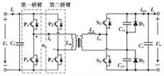
图9是本发明的功率模块拓扑的双向结构示意图,将三电平整流桥中二极管D1~D4替换成双向功率器件,可以实现输入输出之间功率的双向流动和控制。9 is a schematic diagram of a bidirectional structure of the power module topology of the present invention. The diodes D1- D4 in thethree -level rectifier bridge are replaced with bidirectional power devices, which can realize bidirectional flow and control of power between input and output.
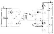
图10是本发明的功率模块拓扑衍生示意图,将H桥替代变压器副边的三电平整流桥,同样具备宽电压范围输出能力和功率调节能力,开关损耗较小,效率较高,变压器体积小,成本低。Fig. 10 is a schematic diagram of the topology derivation of the power module of the present invention. The H bridge is replaced by the three-level rectifier bridge on the secondary side of the transformer. It also has a wide voltage range output capability and power regulation capability, with small switching loss, high efficiency, and small transformer volume. ,low cost.
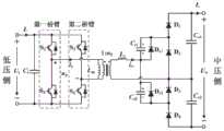
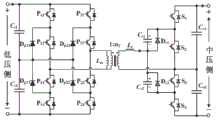
图11是本发明的一种功率模块拓扑衍生示意图,将三电平NPC半桥替代变压器原边的H桥,NPC开关管的电压应力减半;同样也可以采用如图12所示的NPC全桥替代H桥。Fig. 11 is a schematic diagram of a topology derivative of a power module of the present invention. The three-level NPC half-bridge is replaced by the H-bridge on the primary side of the transformer, and the voltage stress of the NPC switch tube is halved; The bridge replaces the H-bridge.
最后应当说明的是:以上具体实施方式和实施例子仅用于说明发明的技术方案而并非对其进行限制,对于本发明所覆盖的技术领域的普通技术人员而言,在不脱离本发明精神和构思的前提之下,对本发明的具体实施方式和实施例子进行简单修改、类比推理或同等替换,均视为属于本发明的权利要求书保护范围之中。Finally, it should be noted that the above specific embodiments and examples are only used to illustrate the technical solutions of the invention rather than limit them. For those of ordinary skill in the technical field covered by the present invention, without departing from the spirit and Under the premise of the concept, any simple modification, analogical reasoning or equivalent replacement to the specific embodiments and examples of the present invention are deemed to fall within the protection scope of the claims of the present invention.
Claims (7)
Translated fromChinesePriority Applications (1)
| Application Number | Priority Date | Filing Date | Title |
|---|---|---|---|
| CN202010457172.7ACN111555633B (en) | 2020-05-26 | 2020-05-26 | Direct-current transformer for new energy direct-current grid connection and control method thereof |
Applications Claiming Priority (1)
| Application Number | Priority Date | Filing Date | Title |
|---|---|---|---|
| CN202010457172.7ACN111555633B (en) | 2020-05-26 | 2020-05-26 | Direct-current transformer for new energy direct-current grid connection and control method thereof |
Publications (2)
| Publication Number | Publication Date |
|---|---|
| CN111555633Atrue CN111555633A (en) | 2020-08-18 |
| CN111555633B CN111555633B (en) | 2023-03-24 |
Family
ID=72006702
Family Applications (1)
| Application Number | Title | Priority Date | Filing Date |
|---|---|---|---|
| CN202010457172.7AActiveCN111555633B (en) | 2020-05-26 | 2020-05-26 | Direct-current transformer for new energy direct-current grid connection and control method thereof |
Country Status (1)
| Country | Link |
|---|---|
| CN (1) | CN111555633B (en) |
Cited By (2)
| Publication number | Priority date | Publication date | Assignee | Title |
|---|---|---|---|---|
| CN113783206A (en)* | 2021-07-16 | 2021-12-10 | 云南电网有限责任公司电力科学研究院 | Voltage disturbance prevention frequency modulation method and system for new energy station |
| CN119298692A (en)* | 2024-09-14 | 2025-01-10 | 南京师范大学 | A high-gain bipolar grid-connected inverter for photovoltaic hydrogen production system |
Citations (4)
| Publication number | Priority date | Publication date | Assignee | Title |
|---|---|---|---|---|
| CN101071994A (en)* | 2006-05-10 | 2007-11-14 | 周春香 | Integrated three-phase AC/DC isolated two-way converter |
| CN109600049A (en)* | 2019-01-23 | 2019-04-09 | 哈尔滨工业大学 | A kind of DC solid transformer |
| CN110768534A (en)* | 2019-10-21 | 2020-02-07 | 华中科技大学 | Isolated double-half-bridge ANPC active bridge three-level DC/DC converter |
| CN110829848A (en)* | 2019-10-21 | 2020-02-21 | 华中科技大学 | Isolated double-full-bridge active neutral-point clamped three-level DC/DC converter |
- 2020
- 2020-05-26CNCN202010457172.7Apatent/CN111555633B/enactiveActive
Patent Citations (4)
| Publication number | Priority date | Publication date | Assignee | Title |
|---|---|---|---|---|
| CN101071994A (en)* | 2006-05-10 | 2007-11-14 | 周春香 | Integrated three-phase AC/DC isolated two-way converter |
| CN109600049A (en)* | 2019-01-23 | 2019-04-09 | 哈尔滨工业大学 | A kind of DC solid transformer |
| CN110768534A (en)* | 2019-10-21 | 2020-02-07 | 华中科技大学 | Isolated double-half-bridge ANPC active bridge three-level DC/DC converter |
| CN110829848A (en)* | 2019-10-21 | 2020-02-21 | 华中科技大学 | Isolated double-full-bridge active neutral-point clamped three-level DC/DC converter |
Cited By (3)
| Publication number | Priority date | Publication date | Assignee | Title |
|---|---|---|---|---|
| CN113783206A (en)* | 2021-07-16 | 2021-12-10 | 云南电网有限责任公司电力科学研究院 | Voltage disturbance prevention frequency modulation method and system for new energy station |
| CN113783206B (en)* | 2021-07-16 | 2023-11-21 | 云南电网有限责任公司电力科学研究院 | A frequency modulation method and system for new energy stations that are resistant to voltage disturbances |
| CN119298692A (en)* | 2024-09-14 | 2025-01-10 | 南京师范大学 | A high-gain bipolar grid-connected inverter for photovoltaic hydrogen production system |
Also Published As
| Publication number | Publication date |
|---|---|
| CN111555633B (en) | 2023-03-24 |
Similar Documents
| Publication | Publication Date | Title |
|---|---|---|
| CN112928919B (en) | Isolated high-frequency resonant DC-DC converter with wide output voltage range and method | |
| CN101902142B (en) | Diode clamping five-level dual buck half-bridge inverter | |
| CN110957922A (en) | Single-stage high-frequency isolated bidirectional direct-current converter and grid-connected energy storage system | |
| CN109327158B (en) | Current type grid-connected inverter integrating power decoupling and buck-boost functions | |
| CN111193421B (en) | Three-phase isolation AC-DC converter | |
| CN105226925B (en) | A kind of inverse-excitation type single-phase inverter and its control method | |
| CN107919797B (en) | Wide input range interleaving parallel connection type high-efficiency boost direct-current converter for fuel cell | |
| CN106505869A (en) | A hybrid resonant full-bridge converter and control method for new energy DC grid-connected | |
| CN110611451A (en) | A photovoltaic inverter based on gallium nitride device and its control method | |
| CN108736756B (en) | Improved double-auxiliary resonant-pole three-phase soft switching inverter circuit | |
| CN110504833A (en) | A High Gain Boost Converter Based on Active Network | |
| CN211127589U (en) | Single-stage high-frequency isolated bidirectional direct-current converter and grid-connected energy storage system | |
| CN111555633B (en) | Direct-current transformer for new energy direct-current grid connection and control method thereof | |
| CN114759802A (en) | ZVZCS full-bridge three-level DCDC converter | |
| CN106452153A (en) | Variable-topology Trans-Z-source inverter | |
| CN201018423Y (en) | A Full-Bridge Converter Realizing Zero-Voltage and Zero-Current Switching with Lag Bridge Arm | |
| CN204947919U (en) | A kind of parallel resonance no-voltage photovoltaic power generation apparatus | |
| CN205754197U (en) | Photovoltaic power generation system with low energy consumption auxiliary circuit | |
| CN210578299U (en) | Photovoltaic inverter based on gallium nitride device | |
| CN116418238B (en) | Three-switch half-bridge wide-range LLC resonant converter and use method thereof | |
| CN204948016U (en) | A kind of photovoltaic power generation apparatus adopting zero voltage switch auxiliary resonance | |
| CN204696954U (en) | A three-phase resonant pole photovoltaic inverter | |
| CN204696955U (en) | A Photovoltaic Inverter Using Transformer Auxiliary Resonance | |
| CN210518137U (en) | Switch capacitor type high-frequency power pulse generating circuit | |
| CN106849177A (en) | A kind of buck-boost grid-connected inverter |
Legal Events
| Date | Code | Title | Description |
|---|---|---|---|
| PB01 | Publication | ||
| PB01 | Publication | ||
| SE01 | Entry into force of request for substantive examination | ||
| SE01 | Entry into force of request for substantive examination | ||
| GR01 | Patent grant | ||
| GR01 | Patent grant |