CN1115518A - Method and apparatus for inverter control - Google Patents
Method and apparatus for inverter controlDownload PDFInfo
- Publication number
- CN1115518A CN1115518ACN95101650ACN95101650ACN1115518ACN 1115518 ACN1115518 ACN 1115518ACN 95101650 ACN95101650 ACN 95101650ACN 95101650 ACN95101650 ACN 95101650ACN 1115518 ACN1115518 ACN 1115518A
- Authority
- CN
- China
- Prior art keywords
- motor
- speed
- inverter
- pulse width
- inverter control
- Prior art date
- Legal status (The legal status is an assumption and is not a legal conclusion. Google has not performed a legal analysis and makes no representation as to the accuracy of the status listed.)
- Granted
Links
Images


Classifications
- H—ELECTRICITY
- H02—GENERATION; CONVERSION OR DISTRIBUTION OF ELECTRIC POWER
- H02P—CONTROL OR REGULATION OF ELECTRIC MOTORS, ELECTRIC GENERATORS OR DYNAMO-ELECTRIC CONVERTERS; CONTROLLING TRANSFORMERS, REACTORS OR CHOKE COILS
- H02P21/00—Arrangements or methods for the control of electric machines by vector control, e.g. by control of field orientation
- H02P21/0003—Control strategies in general, e.g. linear type, e.g. P, PI, PID, using robust control
Landscapes
- Engineering & Computer Science (AREA)
- Power Engineering (AREA)
- Control Of Ac Motors In General (AREA)
- Inverter Devices (AREA)
Abstract
Translated fromChinese
Description
Translated fromChinese本发明涉及一种逆变器控制设备和驱动马达的方法的改进。The present invention relates to improvements in an inverter control device and a method of driving a motor.
为了便于理解,下面将结合例子来描述用于驱动感应马达的矢量控制逆变器控制设备(以下称为“逆变器控制设备”)。For ease of understanding, a vector control inverter control device for driving an induction motor (hereinafter referred to as "inverter control device") will be described below with examples.
图25、26、27和28显示了传统的控制型矢量控制逆变器控制设备。图25是主要装置图,图26是矢量控制框图,图27是PWM操作原理图,且图28(a)—28(b—3)是逆变器控制设备的轮廓图。Figures 25, 26, 27 and 28 show conventional control-type vector control inverter control devices. 25 is a main device diagram, FIG. 26 is a vector control block diagram, FIG. 27 is a PWM operation principle diagram, and FIGS. 28(a)-28(b-3) are outline diagrams of inverter control equipment.
在图25中,标号1表示一个三相交流电源,2表示由二极管等组成的整流电路—它从三相交流电源1获得直流电压,3表示直流电压平滑滤波器,4表示由诸如晶体管的开关器件组成的逆变器电路,5表示一个作为负载的感应电机(以下称为“马达”),6表示检测马达5的速度的速度检测器,7表示提供马达5的速度依据的速度指令电路,8表示一个矢量控制运算电路—它根据速度指令电路7的指令值ωr*与速度检测器6的检测输出ωr之间的偏离对马达5的初级电流指令值I*进行运算,9表示一个电流检测器—它检测马达5的初级电流检测值I,10表示一个脉冲宽度调制控制电路(以下称为“PWM电路”)—它根据所述初级电流指令值I*与初级电流检测值I之间的偏离来产生使开关装置通—断的信号,且11表示一个散热器,它散掉由装在整流电路2和逆变器电路4中的装置产生的热量。In Fig. 25,
在上述设置中,现在根据图26的矢量控制框图来描述矢量控制运算电路8的内部设置。在此图中,81表示一个运算放大器,它放大速度指令电路7的指令值ωr*与速度检测器6的检测值ωr之间的差,并输出用于力矩Iq*的电流指令值;82表示一个次级磁通量图形发生器,它根据速度检测器6的检测值ωr来产生次级磁通量指令值Φ2*;83表示一个算法电路,它根据次级磁通量图形发生器82的输出来产生一个估计的次级磁通量Φ2和激励电流分量指令值Id*;84表示一个初级电流幅度发生器,它根据用于力矩Iq*的电流指令值和激励电流分量指令值Id*来产生一个初级电流幅度值|I1*|;85表示一个力矩幅角算法电路,它从力矩Iq*的电流指令值和激励电流分量指令值Id*对力矩幅角θ*进行运算;86表示一个滑差频率指令算法电路,它从用于力矩Iq*的所述电流指令值和估计的次级磁通量Φ2对一个滑差频率指令ωs*进行运算;且87表示一个初级电流指令算法电路,它根据由力矩幅角算法电路85的输出|I1*|、力矩幅角算法电路85的输出θ*和滑差频率指令算法电路86的输出ωs*与速度检测器6的输出ωr之和组成的逆变器频率指令ω0来对初级电流指令值I*进行计算。所述电路组成了矢量控制运算电路8。In the above-mentioned setting, the internal setting of the vector
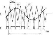
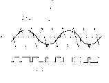
在这种设置中,现在将根据图27的PWM操作原理图,来描述PWM电路10的内部设置。在此图中,1001表示ΔI或初级电流指令值I*与初级电流检测值I之间的偏离,1002表示用于斩波ΔI的三角波,且1003表示开关信号一它作为所述ΔI与三角波之间的比较结果,当ΔI大于该三角波时导通且当ΔI小于该三角波时关断。该三角波的周期一般被称为PWM频率且在下面被称为“fpwm”。这些装置,诸如装在逆变器电路4中的功率晶体管,(以下称为“开关装置”)在这种开关信号1003的控制下被通—断。In this arrangement, the internal arrangement of the
图28(a)—28(b—3)是包含所述设置的逆变器控制设备的轮廓图。在这些附图中,标号11a、11b和11c表示了散热器,12表示一个电路,且13表示一个冷却风扇。当负载或马达受到逆变器控制设备的驱动时,fpwm通常被设定为大约3kHz。然而,由于处于人所能够听见的范围内,大约为3kHz的频率在马达运行时产生了讨厌的噪声。为了降低或基本上消除这种噪声,经常将fpwm设定在人的听力范围以外或大约为10kHz—20kHz。另外,当马达以非常快的速度转动时(大约为50000rpm或更高),必须将fpwm设定在并正常情况下更高的值(大约5kHz—10kHz),以保持如下的控制性能,因为马达电流的频率更高。在这些图中,图28(a)显示了逆变器控制设备的轮廓,其中fpwm大约为3kHz;且图28(b—1)、28(b—2)和28(b—3)显示了当fpwm为大约5kHz—20kHz的逆变器控制设备的轮廓。随着fpwm增大,逆变器电路4中的开关装置的开关损耗上升且产生的热量增大。因此,散热器11b、11c必须比图28(b—1)和28(b—2)中的散热器11a大,或者必须在外侧设置冷却风扇13,如图28(b—3)所示,以改善散热能力。28(a)-28(b-3) are outline views of the inverter control apparatus including the arrangement. In these drawings,
在上述驱动马达的传统逆变器控制设备中,当需要以低噪声驱动马达时,要将fpwm设定在比正常情况更高的值。另外,当需要以非常快的转速驱动马达时,需要将fpwm设定在比正常情况更高的值。在传统上,作为对付开关装置由于如上所述地设定在更高值的fpwm而产生的热量增大的措施,将逆变器控制设备的散热器作得更大或者在外侧设置额外的冷却风扇。因此,当以低噪声或快的转速驱动马达时,逆变器控制设备的尺寸或成本因而被增大了。In the above conventional inverter control apparatus for driving a motor, when it is necessary to drive the motor with low noise, fpwm is set to a higher value than normal. Also, when the motor needs to be driven at very fast speeds, fpwm needs to be set to a higher value than normal. Traditionally, as a countermeasure against the increased heat generated by the switching gear due to fpwm set at a higher value as described above, the heat sink of the inverter control device was made larger or additional cooling was provided on the outside fan. Therefore, when the motor is driven with low noise or fast rotation speed, the size or cost of the inverter control device is thus increased.
因此,本发明的一个目的,是通过提供一种马达驱动逆变器控制设备来克服上述问题,当以低噪声或非常快的转速驱动马达时,该逆变器控制设备不需要大的尺寸和外形,因而不会导致成本的增大。It is therefore an object of the present invention to overcome the above-mentioned problems by providing a motor-driven inverter control device which does not require a large size and Shape, so it will not lead to an increase in cost.
为了实现上述目的,本发明涉及的马达驱动逆变器控制设备具有以下的一或多个特征:In order to achieve the above object, the motor drive inverter control device involved in the present invention has one or more of the following features:
(1)低速—高速PWM切换,由在马达的低速和高速范围之间切换fpwm的装置提供;(1) Low-speed-high-speed PWM switching, provided by means of switching fpwm between the low-speed and high-speed ranges of the motor;
(2)恒定力矩恒定输出PWM切换,由在马达的恒定力矩特性区和恒定输出区之间切换fpwm并将fpwm与速度函数一起设定在恒定输出区中的装置提供;(2) Constant torque constant output PWM switching, provided by a device that switches fpwm between the constant torque characteristic region and the constant output region of the motor and sets fpwm in the constant output region together with the speed function;
(3)加速/减速稳定状态PWM切换,由只在马达加速/减速期间将fpwm设定在更高值的装置提供;(3) Acceleration/deceleration steady-state PWM switching provided by a device that sets fpwm at a higher value only during motor acceleration/deceleration;
(4)速度—位置PWM切换,由只在位置环操作将fpwm设定在更高值的装置提供;(4) Speed-position PWM switching, provided by a device that sets fpwm at a higher value only in the position loop operation;
(5)等效负载因子PWM切换,由对马达负载因子进行运算并能够根据该负载因子来改变fpwm的装置提供;(5) Equivalent load factor PWM switching, provided by a device that calculates the motor load factor and can change fpwm according to the load factor;
(6)散热器—环境温度差PWM切换,由检测散热器的温度和逆变器控制设备的环境温度并能够根据它们之间的差来改变fpwm的装置提供;(6) Radiator-ambient temperature difference PWM switching, provided by a device that detects the temperature of the radiator and the ambient temperature of the inverter control device and can change fpwm according to the difference between them;
(7)由在固定和改变fpwm之间进行选择的装置进行的切换;以及(7) switching by means of selecting between fixing and changing fpwm; and
(8)当fpwm受到切换时,将开关装置的栅极关闭一次。(8) When the fpwm is switched, turn off the gate of the switching device once.
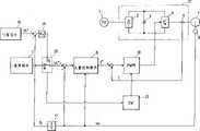
图1是根据本发明的用于驱动马达的逆变器控制设备的一个实施例的主设置图;1 is a main setup diagram of one embodiment of an inverter control device for driving a motor according to the present invention;
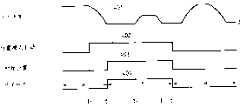
图2是根据本发明的用于驱动马达的逆变器控制设备的一个实施例的操作时序图;2 is an operation timing chart of one embodiment of an inverter control device for driving a motor according to the present invention;
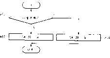
图3是根据本发明的用于驱动马达的逆变器控制设备的一个实施例的操作流程图;3 is an operation flowchart of one embodiment of an inverter control device for driving a motor according to the present invention;
图4是根据本发明的用于驱动马达的逆变器控制设备的第二实施例的主设置图;4 is a main setup diagram of a second embodiment of an inverter control device for driving a motor according to the present invention;
图5是根据本发明的用于驱动马达的逆变器控制设备的第二实施例的操作时序图;5 is an operation timing chart of a second embodiment of the inverter control device for driving a motor according to the present invention;
图6是根据本发明的用于驱动马达的逆变器控制设备的第二实施例的操作流程图。6 is an operation flowchart of the second embodiment of the inverter control apparatus for driving a motor according to the present invention.
图7是根据本发明的用于驱动马达的逆变器控制设备的第三实施例的主设置图。7 is a main setup diagram of a third embodiment of an inverter control device for driving a motor according to the present invention.
图8是根据本发明的用于驱动马达的逆变器控制设备的第三实施例的操作时序图。8 is an operation timing chart of the third embodiment of the inverter control device for driving a motor according to the present invention.
图9是根据本发明的用于驱动马达的逆变器控制设备的第三实施例的操作流程图。9 is an operation flowchart of the third embodiment of the inverter control apparatus for driving a motor according to the present invention.
图10是根据本发明的用于驱动马达的逆变器控制设备的第四实施例的主设置图。10 is a main setup diagram of a fourth embodiment of an inverter control device for driving a motor according to the present invention.
图11是根据本发明的用于驱动马达的逆变器控制设备的第四实施例的操作时序图。11 is an operation timing chart of the fourth embodiment of the inverter control device for driving a motor according to the present invention.
图12是根据本发明的用于驱动马达的逆变器控制设备的第四实施例的操作流程图。12 is an operation flowchart of the fourth embodiment of the inverter control apparatus for driving a motor according to the present invention.
图13是根据本发明的用于驱动马达的逆变器控制设备的第五实施例的主设置图。13 is a main setup diagram of a fifth embodiment of the inverter control apparatus for driving a motor according to the present invention.
图14是根据本发明的用于驱动马达的逆变器控制设备的第五实施例的操作时序图。14 is an operation timing chart of the fifth embodiment of the inverter control apparatus for driving a motor according to the present invention.
图15是根据本发明的用于驱动马达的逆变器控制设备的第五实施例的操作流程图。15 is an operation flowchart of the fifth embodiment of the inverter control apparatus for driving a motor according to the present invention.
图16是根据本发明的用于驱动马达的逆变器控制设备的第六实施例的主设置图。16 is a main setup diagram of a sixth embodiment of the inverter control apparatus for driving a motor according to the present invention.
图17是根据本发明的用于驱动马达的逆变器控制设备的第六实施例的操作时序图。17 is an operation timing chart of the sixth embodiment of the inverter control device for driving a motor according to the present invention.
图18是根据本发明的用于驱动马达的逆变器控制设备的第六实施例的操作流程图。18 is an operation flowchart of the sixth embodiment of the inverter control apparatus for driving a motor according to the present invention.
图19是根据本发明的用于驱动马达的逆变器控制设备的第七实施例的主设置图。Fig. 19 is a main setup diagram of a seventh embodiment of the inverter control apparatus for driving a motor according to the present invention.
图20是根据本发明的用于驱动马达的逆变器控制设备的第七实施例的操作时序图。20 is an operation timing chart of the seventh embodiment of the inverter control apparatus for driving a motor according to the present invention.
图21是根据本发明的用于驱动马达的逆变器控制设备的第七实施例的操作流程图。21 is an operation flowchart of the seventh embodiment of the inverter control apparatus for driving a motor according to the present invention.
图22是根据本发明的用于驱动马达的逆变器控制设备的第八实施例的主设置图。22 is a main setup diagram of an eighth embodiment of the inverter control apparatus for driving a motor according to the present invention.
图23是根据本发明的用于驱动马达的逆变器控制设备的第八实施例的操作时序图。23 is an operation timing chart of the eighth embodiment of the inverter control apparatus for driving a motor according to the present invention.
图24是根据本发明的用于驱动马达的逆变器控制设备的第八实施例的操作流程图。24 is an operation flowchart of the eighth embodiment of the inverter control apparatus for driving a motor according to the present invention.
图25是传统的用于驱动马达的逆变器控制设备的主设置图。Fig. 25 is a main setup diagram of a conventional inverter control device for driving a motor.
图26是传统的用于驱动马达的逆变器控制设备的矢量控制框图。Fig. 26 is a vector control block diagram of a conventional inverter control device for driving a motor.
图27是传统的用于驱动马达的逆变器控制设备的PWM操作原理图。FIG. 27 is a schematic diagram of a PWM operation of a conventional inverter control device for driving a motor.
图28(a)—28(b—3)是传统的用于驱动马达的逆变器控制设备的轮廓图。28(a)-28(b-3) are outline views of a conventional inverter control device for driving a motor.
在上述附图中,在本发明的几个实施例中,与现有技术中的部分相同的部分由相同的标号表示。In the above drawings, in several embodiments of the present invention, the same parts as those in the prior art are denoted by the same reference numerals.
下面结合图1描述本发明的第一实施例;图1是用于驱动马达的逆变器控制设备的主设置图。A first embodiment of the present invention will be described below with reference to FIG. 1; FIG. 1 is a main setup diagram of an inverter control device for driving a motor.
在此图中,标号14表示一个低速—高速PWM切换电路14,它具有接收速度检测器6的检测输出ωr、判定当前马达速度是处于低速范围还是处于高速范围、并切换PWM电路10的fpwm的装置。In this figure, reference numeral 14 denotes a low-speed-high-speed PWM switching circuit 14 having a function of receiving the detection output ωr of the speed detector 6, judging whether the current motor speed is in the low-speed range or in the high-speed range, and switching fpwm of the
图2是本发明的第一实施例用于驱动马达的逆变器控制设备的操作时序图。现在根据图2来描述该实施例的操作原理。2 is an operation timing chart of the inverter control device for driving a motor according to the first embodiment of the present invention. The operating principle of this embodiment will now be described with reference to FIG. 2 .
在图2中,显示了图27中的PWM电路10的内部设置,下面将描述fpwm与马达电流频率fm之间的关系。一般地,要在不影响控制性能的情况下驱动马达,至少需要满足以下的条件:In FIG. 2, the internal arrangement of the
fpwm>6×fm即,在马达电流的一个周期中至少应该进行六次切换。图2显示了六次切换的出现。为了给出一个具体的例子以便于理解,当两极感应马达以50000rpm转动时:fpwm>6×fm That is, at least six switching times should be performed in one cycle of the motor current. Figure 2 shows the occurrence of six switches. To give a concrete example for easy understanding, when a two pole induction motor is turning at 50000rpm:
fm=P×ωr/12=(2×50000/120)=0.833kHz因此,fm=P×ωr/12=(2×50000/120)=0.833kHz Therefore,
fpwm>6×fm=6×0.833kHz=5kHzfpwm>6×fm=6×0.833kHz=5kHz
如果马达以25000rpm转动,fpwm可以是2.5kHz。If the motor is turning at 25000rpm, the fpwm can be 2.5kHz.
图3是本发明的第一实施例的用于驱动马达的逆变器控制设备的操作流程图。现在结合图3描述由低速—高速PWM切换电路14进行的操作的流程例子。首先,在步骤101判定马达速度r是否小于25000rpm。如果速度小于25000rpm,则在步骤102将fpwm设定在2.5kHz。如果不小于25000rpm,更在步骤103将fpwm设定在5kHz。3 is an operation flowchart of the inverter control device for driving a motor of the first embodiment of the present invention. An example of the flow of operations performed by the low-speed-high-speed PWM switching circuit 14 will now be described with reference to FIG. 3 . First, it is determined in
根据传统技术,fpwm在低速范围中也被设定在5kHz,以便于50000rpm驱动马达,这在进行较多次的重切削且马达电流增大的情况下,在低速范围中使开关装置产生出的热量增大。如所解释的,这造成了逆变器控制设备的尺寸的增大。According to the conventional technology, fpwm is also set at 5kHz in the low speed range to drive the motor at 50000rpm, which makes the switchgear produce excessive power in the low speed range when more heavy cutting is performed and the motor current increases. Increased heat. As explained, this causes an increase in the size of the inverter control device.
根据本发明,fpwm在低速范围中与现有技术的相同(其中进行较多次的重切削),以防止开关装置产生的热量增大。然而,在主要进行轻切削的高速范围中,fpwm得到了提高,以保持控制性能。其结果,能够用具有图28(a)所示的传统设备的特征的逆变器控制设备,来如下所述地保持非常快的转速。According to the present invention, fpwm is the same as the prior art in the low speed range (where more heavy cuts are made) to prevent an increase in the heat generated by the switching device. However, in the high-speed range where light cutting is predominantly performed, fpwm is increased to maintain control performance. As a result, with the inverter control device having the characteristics of the conventional device shown in FIG. 28( a ), it is possible to maintain a very high rotational speed as described below.
另外,在本发明中,fpwm的切换速度,就是直接装在马达上的速度检测器检测的速度。因此,能够实时地掌握马达的实际速度,且在切换时序中不会出现速度检测延迟,以提供平滑的加速/减速特性。In addition, in the present invention, the switching speed of fpwm is the speed detected by the speed detector directly mounted on the motor. Therefore, the actual speed of the motor can be grasped in real time, and there is no speed detection delay in the switching timing to provide smooth acceleration/deceleration characteristics.
除了本发明的实施例以外,fpwm的切换速度可以由一个速度指令确定或者从马达电流的频率估计。如果采用速度指令,则在速度指令与实际速度之间一般有一个延迟,造成切换的速度与所希望用于切换的实际速度有所不同。另外,如果采用从电流频率估计的速度,则由于具有PWM导出的谐波的电流波形,会产生速度估计值误差,使得无法以精确的速度进行切换。因此,与本发明的第一实施例相比,难于以这种方法提供平滑的加速/减速特性。In addition to embodiments of the present invention, the switching speed of fpwm can be determined by a speed command or estimated from the frequency of the motor current. If a speed command is used, there is typically a delay between the speed command and the actual speed, causing the switched speed to differ from the actual speed desired for switching. In addition, if the speed estimated from the current frequency is used, due to the current waveform with PWM-derived harmonics, there will be speed estimation error, making it impossible to switch at an accurate speed. Therefore, compared with the first embodiment of the present invention, it is difficult to provide smooth acceleration/deceleration characteristics in this way.
现在结合图4来描述本发明的第二实施例;图4是用于驱动马达的逆变器控制设备的主设置图。在此图中,15表示一个恒定力矩一恒定输出PWM切换电路,它接收速度检测器6的检测输出ωr和包含在矢量控制运算电路8中的次级磁通量图形发生器的马达基速ωb、判定当前马达速度是处于恒定力矩区内(即小于ωb)还是处于恒定输出区内(即不小于ωb),并切换PWM电路10的fpwm。A second embodiment of the present invention will now be described with reference to FIG. 4; FIG. 4 is a main setup diagram of an inverter control device for driving a motor. In this figure, 15 represents a constant torque-constant output PWM switching circuit, which receives the detection output ωr of the speed detector 6 and the motor base speed ωb of the secondary magnetic flux pattern generator included in the vector
图5是根据本发明的第二实施例的用于驱动马达的逆变器控制设备的操作时序图。现在将结合图5来描述本实施例的操作原理。5 is an operation timing chart of an inverter control device for driving a motor according to a second embodiment of the present invention. The operating principle of this embodiment will now be described with reference to FIG. 5 .
图5显示了马达特性,其中201表示输出—速度特性,202表示力矩—速度特性,203表示次级磁通量—速度特性,且204表示初级电流—速度特性。感应马达的输出特性一般被设计成在小于ωb的速度区中如201所示地使输出与速度成比例地增大,且在不小于ωb的速度区中使输出保持恒定。用于切换ωb的该速度通常被称为基速。202明显地表示了在小于ωb时的恒定力矩特性(恒定力矩区)和在不小于ωb时的恒定输出特性(恒定输出区)。另外,与力矩成比例地,次级磁通量如203所示地象力矩那样地弯曲。另外,马达的初级电流,即流过逆变器电路4的开关装置的电流,在小于ωb处如204所示地是恒定的,且在超过ωb时逐渐减小。5 shows motor characteristics, where 201 represents output-speed characteristics, 202 represents torque-speed characteristics, 203 represents secondary magnetic flux-speed characteristics, and 204 represents primary current-speed characteristics. The output characteristics of the induction motor are generally designed to increase the output in proportion to the speed as indicated by 201 in a speed region smaller than ωb, and keep the output constant in a speed region not smaller than ωb. This speed for switching ωb is generally called the base speed. 202 clearly shows the constant torque characteristic (constant torque region) when smaller than ωb and the constant output characteristic (constant output region) when not smaller than ωb. In addition, in proportion to the moment, the secondary magnetic flux bends like a moment as indicated by 203 . In addition, the primary current of the motor, that is, the current flowing through the switching device of the
现在描述fpwm、马达初级电流和开关装置所产生的热量之间的关系。一般地,开关装置的损耗被分成:The relationship between fpwm, motor primary current and heat generated by switching devices is now described. In general, switching device losses are divided into:
(1)与fpwm和马达初级电流成正比的切换损耗;以及(1) switching losses proportional to fpwm and motor primary current; and
(2)与马达初级电流成正比的稳定损耗。(2) Steady losses proportional to the motor primary current.
另外,马达通常以低噪声运行,以减小令人讨厌的马达激励噪声,这种噪声特别容易在小于ωb(此时次级磁通量大)时发生。因此,fpwm不一定在所有的速度区中都高以保持低噪声,且本发明的目的是减小在次级磁通量和马达初级电流小的恒定输出区中的fpwm,以防止总的开关装置损耗增大。In addition, the motor is usually run with low noise to reduce the annoying motor excitation noise, which is especially prone to occur below ωb (when the secondary magnetic flux is large). Therefore, fpwm is not necessarily high in all speed regions to keep noise low, and the purpose of the present invention is to reduce fpwm in constant output regions where secondary flux and motor primary current are small, to prevent total switching device losses increase.
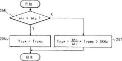
图6是根据本发明的第二实施例的用于驱动马达的逆变器控制设备的操作流程图。现在结合图6描述由恒定力矩—恒定输出PWM切换电路15进行的操作的流程图。首先,在步骤205判定马达速度ωr是否小于ωb。如果该速度小于ωb,则在步骤206将fpwm设定为fpwm0=10—20kHz。如果该速度不小于ωb,则在步骤207,在fpwm>3kHz的条件下,将fpwm设定为(ωb/ωr)×fpwm0。6 is an operation flowchart of the inverter control device for driving a motor according to the second embodiment of the present invention. A flowchart of the operation performed by the constant torque-constant output
根据现有技术,虽然主要应该是在小于ω b的速度区中降低马达噪声,但由于没有fpwm切换功能,在不小于ωb的速度区中fpwm也被设定在10—20kHz,这导致了开关装置产生的热量在所有速度区中的增大,从而造成了逆变器控制设备的尺寸的增大。According to the prior art, although it should be mainly to reduce the motor noise in the speed range less than ωb, since there is no fpwm switching function, fpwm is also set at 10-20kHz in the speed range not less than ωb, which leads to switching The heat generated by the device increases in all speed regions, resulting in an increase in the size of the inverter control device.
根据本发明,在次级磁通量大的恒定力矩区中fpwm得到了提高,而在次级磁通量以更高的速度减小的恒定输出区中fpwm被逐渐减小,以防止总的开关装置产生热量的增大。其结果,是能够用与图28(a)所示的传统设计相同的逆变器控制设备,来保证马达的低噪声运行,如下所述。现在描述本实施例与第一实施例的不同。第一实施例在低速范围和高速范围之间切换fpwm(在低速范围中为低fpwm且在高速范围中为高fpwm),且第二实施例在恒定力矩区与恒定输出区之间切换fpwm(在恒定力矩区中为高fpwm且在恒定输出区中为低fpwm)。两个实施例在以给定的速度切换fpwm上是类似的,但在以下方面不同:According to the present invention, fpwm is increased in the constant torque region where the secondary magnetic flux is large, and is gradually reduced in the constant output region where the secondary magnetic flux decreases at a higher speed to prevent the overall switching device from generating heat increase. As a result, it is possible to ensure low-noise operation of the motor with the same inverter control device as the conventional design shown in Fig. 28(a), as described below. Differences of this embodiment from the first embodiment will now be described. The first embodiment switches fpwm between low speed range and high speed range (low fpwm in low speed range and high fpwm in high speed range), and the second embodiment switches fpwm between constant torque region and constant output region ( High fpwm in constant torque region and low fpwm in constant output region). Both embodiments are similar in switching fpwm at a given speed, but differ in the following ways:
(1)第一实施例采用了满足条件fpwm>6×fm的速度作为切换速度,其中fm=马达初级电流的频率,以便即使在高速范围中也保持控制性能,并降低在低速范围中的产生热量;且(1) The first embodiment adopts, as the switching speed, a speed satisfying the condition fpwm>6×fm, where fm=the frequency of the primary current of the motor, so as to maintain the control performance even in the high-speed range and reduce generation in the low-speed range heat; and
(2)第二实施例采用了马达基速ωb作为切换速度,以在小于基速时降低马达噪声并在不小于基速度时降低热量产生。因此,第一和第二实施例在fpwm在切换速度下减小和增大是彼此相对的,因而它们有不同的效果,即,第一实施例抑制了热量产生并同时保持在非常高的速度范围中的控制性能,而第二实施例抑制了热量产生并同时降低了低速范围中的噪声。(2) The second embodiment adopts the motor base speed ωb as the switching speed to reduce motor noise when less than the base speed and reduce heat generation when not less than the base speed. Therefore, the first and second embodiments are relative to each other in that fpwm decreases and increases at switching speeds, so they have different effects, ie, the first embodiment suppresses heat generation while maintaining very high speeds control performance in the high range, while the second embodiment suppresses heat generation and at the same time reduces noise in the low speed range.
现在结合图7描述本发明的第三实施例;图7是用于驱动马达的逆变器控制设备的主设置图。在此图中,16表示一个加速/减速—稳定状态PWM切换电路,它具有接收速度检测器6的检测输出ωr和速度指令电路7的指令输出ωr*、判定电流马达操作是处于加速/减速操作模式还是处于任何其他稳定一状态操作模式、并切换PWM电路10的fpwm的装置。A third embodiment of the present invention will now be described with reference to FIG. 7; FIG. 7 is a main arrangement diagram of an inverter control device for driving a motor. In this figure, 16 represents an acceleration/deceleration-steady-state PWM switching circuit, which has the detection output ωr of the speed detector 6 and the command output ωr* of the
图8是根据本发明的第三实施例的用于驱动马达的逆变器控制设备的操作时序图。现在根据图8描述该实施例的操作原理。8 is an operation timing chart of an inverter control device for driving a motor according to a third embodiment of the present invention. The principle of operation of this embodiment will now be described with reference to FIG. 8 .
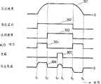
图8显示了判定马达操作模式的方式,其中301表示马达速度,302表示一个马达启动信号,303表示一个达到速度信号,304表示一个加速/减速标志,305表示一个切削负载状态,且306表示一个马达初级电流。首先,当马达启动信号302在时刻t1被导通时,马达加速并在时刻t2达到一个目标速度,从而导通一个达到速度信号303。当负载305随后通过在时刻t3切削而被加到马达上时,马达初级电流306即等于该负载的电流。当负载305在时刻t4被切断时且启动信号302随后在时刻t5被关断时,达到速度信号303关断且马达减速。在t1和t2之间和t5与t6之间,以后面方法判定马达是在加速还是在减速,且加速/减速标志304导通。在这些加速和减速期间,通常还提供马达的最大输出,以减小加速和减速所需的时间,且为了实现这点,马达初级电流也被增大。Fig. 8 shows the way of judging the motor operation mode, wherein 301 represents the motor speed, 302 represents a motor start signal, 303 represents an attained speed signal, 304 represents an acceleration/deceleration flag, 305 represents a cutting load status, and 306 represents a Motor primary current. First, when the
为了以低噪声操作马达,经常强调的是在加速/减速期间减小噪声。这是由于当不进行加速/减速且进行没有切削的空载运行时,通常进行软激励控制,该控制如在本发明的第二实施例中所述地强行减小马达的次级磁通量,以降低马达激励声,因而噪声不是一个问题。另外还由于当不进行加速/减速且进行切削时,在所要切削的工件与工具之间产生的机械切削噪声比马达产生的电激励噪声大得多。因此,经常的情况是马达不需要进行噪声抑制。In order to operate a motor with low noise, it is often emphasized to reduce noise during acceleration/deceleration. This is because when acceleration/deceleration is not performed and no-load operation without cutting is performed, soft excitation control which forcibly reduces the secondary magnetic flux of the motor as described in the second embodiment of the present invention to Reduces motor excitation sound so noise is not an issue. Also because when acceleration/deceleration is not performed and cutting is performed, the mechanical cutting noise generated between the workpiece to be cut and the tool is much larger than the electrical excitation noise generated by the motor. Therefore, it is often the case that the motor does not require noise suppression.
因此,并不是在所有的操作模式下都需要为了降低噪声而增大fpwm,且本发明的目的是只在噪声特别成为问题的加速/减速期间增大fpwm且在其他稳定状态操作期间降低fpwm,从而防止总的开关装置损耗增大。Therefore, it is not necessary to increase fpwm for noise reduction in all operating modes, and the purpose of the present invention is to increase fpwm only during acceleration/deceleration where noise is particularly problematic and to decrease fpwm during other steady state operations, The total switching device loss is thereby prevented from increasing.
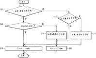
图9是根据本发明的第三实施例的用于驱动马达的逆变器控制设备的操作流程图。现在根据图9描述由加速/减速—稳定状态PWM切换电路16进行的操作流程图。首先,在步骤307判定加速/减速标志是否导通。如果该标志不导通,则在步骤308检查启动指令。如果该指令还没有改变,则在步骤309将fpwm设定为fpwmL=3—5kHz。如果在步骤308所检查的指令已经改变,则在步骤310使加速/减速标志导通并在步骤311将fpwm设定为fpwmH=5—20kHz。如果在步骤307加速/减速标志为导通,则在步骤312检查达到速度信号。如果它为导通,则程序进行到步骤311。如果该信号不导通,则在步骤313将加速/减速标志关断,且操作随后进行到步骤309。9 is an operation flowchart of the inverter control device for driving a motor according to the third embodiment of the present invention. A flow chart of operations performed by the acceleration/deceleration-steady state PWM switching circuit 16 will now be described with reference to FIG. 9 . First, it is determined in
根据传统技术,已经应该主要只在加速/减速操作模式下降低马达噪声,但在所有的模式下fpwm都被设定在10—20kHz,因为没有fpwm切换功能。这造成了开关装置在所有操作模式下所产生的热量的增大,导致了逆变器控制设备尺寸的增大。According to conventional technology, it has been supposed to reduce motor noise mainly only in acceleration/deceleration operation mode, but fpwm is set at 10-20kHz in all modes because there is no fpwm switching function. This causes an increase in the heat generated by the switchgear in all operating modes, leading to an increase in the size of the inverter control equipment.
根据本发明,在马达电流大且马达激励声令人讨厌的加速/减速操作模式下,fpwm被提高,以降低马达噪声,且在马达激励声不成为问题的稳定状态操作模式,fpwm被降低,以防止开关装置产生的总热量的增大。其结果,可以具有用图28(a)所示的传统设备的特征的逆变器控制设备,来保证如下所述的马达低噪声运行。According to the present invention, in the acceleration/deceleration operation mode where the motor current is large and the motor excitation sound is annoying, the fpwm is increased to reduce the motor noise, and in the steady state operation mode where the motor excitation sound is not a problem, the fpwm is lowered, To prevent the increase of the total heat generated by the switchgear. As a result, it is possible to have an inverter control device with the characteristics of the conventional device shown in FIG. 28(a) to ensure low-noise operation of the motor as described below.
本发明的特征,还在于它在不处于加速/减速模式时连续进行了PWM控制。其结果,在稳定状态模式下保证了迅速的响应,且系统能够抵抗干扰负载。这些特征,对于例如在加速/减速模式下降低机器工具的主轴的噪声并同时在稳定状态模式下保持对切削负载的响应是有效的。The present invention is also characterized in that it performs PWM control continuously when not in the acceleration/deceleration mode. As a result, rapid response is guaranteed in steady state mode and the system is resistant to disturbing loads. These features are effective, for example, in reducing the noise of the spindle of a machine tool in acceleration/deceleration mode while maintaining responsiveness to cutting loads in steady state mode.
现在描述本发明的第四实施例。图10是用于驱动马达的逆变器控制设备的主设置图。在此图中,17表示一个对速度检测器6的检测输出ωr进行积分并输出位置检测值θr的积分器;18表示一个位置指令电路,它提供马达5的位置基准θr*;19表示一个位置环增益电路,它将位置指令电路18的输出θr*与积分器17的输出θr之间形成偏离与一个位置环增益KP相乘,并将相乘的结果作为速度指令ωr*而输出;20表示一个速度—位置模式选择开关,它在当前模式为速度指令操作模式时将一个触头切换到位置a,并在当前模式为位置指令操作模式时将该触头切换到位置b;且21表示一个速度—位置PWM切换电路,它具有检测速度—位置模式选择开关20的位置并在速度指令操作模式与位置指令操作模式之间切换PWM电路10的fpwm的装置。A fourth embodiment of the present invention will now be described. Fig. 10 is a main setup diagram of an inverter control device for driving a motor. In this figure, 17 denotes an integrator which integrates the detection output ωr of the speed detector 6 and outputs a position detection value θr; 18 denotes a position instruction circuit which provides a position reference θr* of the
图11是根据本发明的第四实施例的用于驱动马达的逆变器控制设备的操作时序图。图11显示了判定马达的指令模式的方式,其中401表示马达速度,402表示位置模式ON信号,403表示初始位置返回完成信号,且404表示速度—位置模式选择开关20的状态信号。首先,当在位置模式ON信号402在时刻t1被导通时,马达开始减速以返回到起始位置并在时刻t2完成起始位置返回。此时,初始位置返回完成信号403被导通,且同时速度—位置模式选择开关20从位置a移动到位置b。随后,马达在时刻t3在位置指令下运行。当位置模式ON信号402随后在时刻t5被关断时,初始位置返回完成信号403被关断且同时速度—位置模式选择开关20从位置b移到位置a。在t2与t5之间,即在位置指令模式下,马达的速度环要求高响应,如同在C轴控制。因而,在此位置指令模式中,不进行本发明的第三实施例中所述的软激励控制(因为软激励控制相应地降低了速度环增益,影响了速度响应),而是经常进行硬激励控制,从而象上面所述的那样产生大的噪声(激励声)。因此,在该位置指令模式下,马达必须以低噪声运行,但fpwm不用在所有的运行模式下都为此而得到增大。本发明的目的,是只在噪声特别成为问题的位置指令模式下增大fpwm并在其他模式下减小fpwm,从而在位置指令模式下保持速度环响应并防止总的开关装置损耗的增大。11 is an operation timing chart of an inverter control device for driving a motor according to a fourth embodiment of the present invention. 11 shows the way to determine the command mode of the motor, where 401 represents the motor speed, 402 represents the position mode ON signal, 403 represents the initial position return completion signal, and 404 represents the state signal of the speed-position
图12是本发明的第四实施例的用于驱动马达的逆变器控制设备的操作流程图。现在结合图12描述速度—位置模式选择开关20进行的操作的流程。首先,在步骤405判定是否处于位置指令模式。如果不是,则在步骤407执行软激励控制并在步骤408将fpwm设定为fpwmL=3—5kHz。如果在步骤405是处于位置指令模式,则在步骤406判定初始位置返回完成信号是否导通。如果它不导通,则操作进行到步骤407和408。如果在步骤406初始位置返回完成信号导通,则在步骤409执行硬激励控制并在步骤410将fpwm设定为fpwmH=10—20kHz。FIG. 12 is an operation flowchart of the inverter control device for driving a motor of the fourth embodiment of the present invention. Now, the operation flow of the speed-position
根据传统技术,虽然主要只是在位置指令模式下需要降低马达噪声,但由于没有fpwm切换功能,fpwm在所有的模式下都被设定为10—20kHz,这造成了开关装置在所有模式下所产生的热量的增大,导致了逆变器控制设备的尺寸的增大。According to the conventional technology, although the motor noise needs to be reduced mainly only in the position command mode, since there is no fpwm switching function, the fpwm is set to 10-20kHz in all modes, which causes the switching device to generate in all modes The increase in the heat of the inverter leads to an increase in the size of the inverter control device.
根据本发明,在马达激励声令人讨厌的位置指令模式下,fpwm被提高,以降低马达噪声,且在马达激励声不成为问题的其他速度指令模式下,fpwm被降低,以防止开关装置产生的总热量的增大。其结果,可以具有用图28(a)所示的传统设备的特征的逆变器控制设备,来保证如下所述的马达低噪声运行。According to the present invention, fpwm is raised to reduce motor noise in the position command mode where the motor excitation sound is annoying, and is lowered to prevent switching gear in other speed command modes where the motor excitation sound is not a problem. increase in total heat. As a result, it is possible to have an inverter control device with the characteristics of the conventional device shown in FIG. 28(a) to ensure low-noise operation of the motor as described below.
现在结合图13来描述本发明的第五实施例;图13是一种用于驱动马达的逆变器控制设备的主设置图。在此图中,22表示一个等效负载因子PWM切换电路,它具有从矢量控制算法电路8接收用于力矩Iq*的电流指令值、对马达的等效负载因子进行运算、并切换PWM电路10的fpwm的装置。A fifth embodiment of the present invention will now be described with reference to FIG. 13; FIG. 13 is a main arrangement diagram of an inverter control device for driving a motor. In this figure, 22 denotes an equivalent load factor PWM switching circuit, which has the function of receiving a current command value for torque Iq* from the vector
图14是根据本发明的第五实施例的用于驱动马达的逆变器控制设备的操作时序图。现在根据图14来描述该实施例的操作原理。14 is an operation timing chart of an inverter control device for driving a motor according to a fifth embodiment of the present invention. The principle of operation of this embodiment will now be described with reference to FIG. 14 .
图14显示了对马达的等效负载因子进行运算的方式,其中501表示一个马达速度,502表示一个马达启动信号,503表示一个切削负载状态,且504表示一个用于力矩Iq*的电流指令值。首先,当马达启动信号502在时刻t1被导通时,马达被加速并在时刻t2达到目标速度。当负载503通过切削等等而在时刻t3被加到马达上时,与该负载对应的用于力矩Iq*504的电流指令值得到输出。当负载503在时刻t4被切断且马达启动信号502随后在时刻t5被关断时,马达被减速。在t1与t2和t5与t6之间,马达被加速和减速,提供马达的最大输出以减小加速和减速所需的时间,且为了实现这点,用于力矩Iq*的电流指令值通常为用于力矩的额定电流值的120%。Fig. 14 shows how the equivalent load factor of the motor is calculated, where 501 represents a motor speed, 502 represents a motor start signal, 503 represents a cutting load state, and 504 represents a current command value for torque Iq* . First, when the motor start signal 502 is turned on at timet1 , the motor is accelerated and reaches the target speed at timet2 . When a load 503 is applied to the motor at timet3 by cutting or the like, a current command value for the torque Iq* 504 corresponding to the load is output. When the load 503 is switched off at timet4 and the motor enable signal 502 is subsequently switched off at timet5 , the motor is decelerated. Betweent1 andt2 andt5 andt6 , the motor is accelerated and decelerated, providing the maximum output of the motor to reduce the time required for acceleration and deceleration, and to achieve this, the current for the torque Iq* The command value is usually 120% of the rated current value for torque.
假定在t3与t4之间的切削负载为例如80%,且T是用于找到等效负载因子所需的基准时间,则可用下式找到时刻t0与t6之间的等效负载因子:Assuming that the cutting load betweent3 andt4 is, for example, 80%, and T is the reference time required for finding the equivalent load factor, the equivalent load between timest0 andt6 can be found by factor:
等效负载因子=(1.22×{(t2-t1)+(t6-t5)}+0.82×)1/2/TEquivalent load factor = (1.22×{(t2 -t1 )+(t6 -t5 )}+0.82×)1/2 /T
……数学表达式1...
类似地,在下一个周期T(在时刻t6与t7)之间中的等效负载因子,也用类似的数学表达式得到。因此,以类似的方式为各个T周期找到等效负载因子。最好将此时间T设定为单个周期时间(即用于重复相同的操作的时间)的1/5至1/10,因为如果T与例如单个周期时间相匹配,则等效负载因子将始终得到固定,从而不能产生本发明的效果。Similarly, the equivalent load factor in the next cycle T (between instantst6 andt7 ) is also obtained using a similar mathematical expression. Therefore, equivalent load factors are found for each T period in a similar manner. It is better to set this time T as 1/5 to 1/10 of the single cycle time (i.e. the time for repeating the same operation), because if T matches e.g. the single cycle time, the equivalent load factor will always be fixed, so that the effect of the present invention cannot be produced.
为了使马达以低噪声运行,关键是要考虑这种等效负载因子,因为如果为了使马达以低噪声运行而以如上所述的方式过度增大fpwm,则开关装置产生的热量增大,且在最坏的情况下,可能会超过装置的允许温度,从而造成装置的损坏或产生过热警报以保护装置。为了防止这种情况,需要监测等效负载因子并同时控制fpwm的值,以抑制装置产生的热量。In order to run the motor with low noise, it is critical to take this equivalent load factor into account, because if fpwm is excessively increased in the manner described above for the motor to run with low noise, the heat generated by the switching device increases, and In the worst case, the allowable temperature of the device may be exceeded, causing damage to the device or generating an overheating alarm to protect the device. To prevent this, it is necessary to monitor the equivalent load factor and simultaneously control the value of fpwm to suppress the heat generated by the device.
因此,为了降低噪声而将fpwm保持为高,会在装置保护方面产生问题,且本发明的目的是使fpwm根据负载因子而变化,从而防止总开关装置损耗的增大。Therefore, keeping fpwm high in order to reduce noise creates problems in device protection, and the object of the present invention is to vary fpwm according to a load factor, thereby preventing an increase in total switching device loss.
图15是根据本发明的第五实施例的用于驱动马达的逆变器控制设备的操作流程图。现在结合图15来描述由等效负载因子PWM切换电路22进行的操作的流程。首先,在步骤505判定定时器是否计时到了T。如果它还没有计时到T,则在步骤506使定时器继续计时。如果定时器已经计时到了T,则在步骤507将其复置,随后在步骤508用数学表达式1对等效负载因子进行运算,且该计算处理的结果被定义为Load—e(%)。随后,在步骤509将fpwm设定为fpwm0×(Load—c/Load—e)(其中fpwm0=10—20kHz,Load—c=100%)。因此,根据该操作流程,随着等效负载因子增大,fpwm降低。15 is an operation flowchart of the inverter control device for driving a motor according to the fifth embodiment of the present invention. The flow of operations performed by the equivalent load factor PWM switching circuit 22 will now be described with reference to FIG. 15 . First, at step 505, it is determined whether the timer counts down to T. If it has not timed to T, then in step 506 the timer is continued to count. If the timer has counted up to T, it is reset at step 507, and then at step 508,
根据本发明,根据等效负载因子而改变fpwm,以防止开关装置产生的总热量的增大,从而能够采用如图28(a)所示的传统设备相同的逆变器控制设备来以如下所述的方式保持马达的低噪声运行。According to the present invention, fpwm is changed according to the equivalent load factor to prevent the increase of the total heat generated by the switching device, so that the same inverter control device as the conventional device shown in Fig. 28(a) can be used as follows The method described above maintains the low-noise operation of the motor.
作为与本发明的方法类似的一种方法,可以想到的是马达电流的瞬时值或用于力矩Iq*的电流指令值的瞬时值被看作负载因子,且使fpwm能够根据该负载因子改变。然而,用这种方法,由于马达电流和用于力矩Iq*的电流指令值突然改变(即迅速跟踪负载变化),所以fpwm也突然改变,从而使得难于执行稳定的电流控制。As a method similar to the method of the present invention, it is conceivable that the instantaneous value of the motor current or the current command value for the torque Iq* is regarded as a load factor, and fpwm is enabled to be changed according to the load factor. However, with this method, since the motor current and the current command value for the torque Iq* change suddenly (ie, rapidly follow a load change), fpwm also changes suddenly, making it difficult to perform stable current control.
与其相反,本发明在一定的时间内保持了给定的fpwm,从而保证了更稳定的电流控制。On the contrary, the present invention maintains a given fpwm within a certain period of time, thereby ensuring more stable current control.
现在结合图16描述本发明的第六实施例,图16是用于驱动马达的逆变器控制设备的主设置图。在此图中,23表示一个散热器热敏电阻,它装在散热器11上以测量逆变器电路4中的开关装置的温度;24表示一个散热器温度检测电路,它接收散热器热敏电阻23的输出;26表示一个环境温度热敏电阻,它装在安装在控制盒中的逆变器控制设备的周边上,以测量控制盒的环境温度;27表示一个环境温度检测电路,它接收环境温度热敏电阻26的输出;且25表示一个散热器—环境温度差PWM切换电路,它具有接收来自环境温度检测电路27的环境温度数据并根据它们之同的差切换PWM电路10的fpwm的装置。A sixth embodiment of the present invention will now be described with reference to FIG. 16, which is a main setup diagram of an inverter control device for driving a motor. In this figure, 23 represents a radiator thermistor, which is installed on the
图17是根据本发明的第六实施例的用于驱动马达的逆变器控制设备的操作时序图。现在结合图17描述该实施例;图17显示了散热器温度和环境温度的改变。在此图中,601表示散热器温度,602表示环境温度,且603表示马达负载状态。17 is an operation timing chart of an inverter control device for driving a motor according to a sixth embodiment of the present invention. This embodiment will now be described with reference to Figure 17; Figure 17 shows changes in heat sink temperature and ambient temperature. In this figure, 601 represents the radiator temperature, 602 represents the ambient temperature, and 603 represents the motor load status.
在此图中,在时刻t1与t2之间,马达负载603为0,且散热器温度601几乎与环境温度602相同。当负载L1在时刻t2被加上时,散热器温度601上升。当在时刻t3加上了负载L2(>L1)时,散热器温度601进一步上升。当环境温度602在时刻t4在加上了负载L2的情况下上升时,散热器温度601也相应地上升,但温度差相等(散热器温度—环境温度)且在时刻t4与t5之间为常数。当马达负载603在时刻t5再次为零时,散热器温度601下降并最终达到几乎与环境温度602相同的值。In this figure, between time t1 and t2 , the
为了使马达以低噪声运行,关键是要考虑该温度差,因为如果为了使马达以低噪声运行而使fpwm以如上所述的方式过度增大,开关装置产生的热量增大,且在最坏的情况下,可能会超过装置的允许温度,从而造成装置的损坏或产生过热警报以保护装置。为了防止这些,只有散热器温度可以得到检测,且fpwm在度低时被增大,在温度高时被减小,但马达的负载因子还没有得到考虑,因为在此情况下散热器温度包括环境温度。即,由于如果只有环境温度改变则fpwm的值改变,因而即使马达负载因子相同,马达的噪声水平也取决于环境温度。本发明对这种缺陷进行了补偿,即根据散热器温度与环境温度之差而只获得了装置的温度上升,从而估计马达的等效负载因子并同时控制fpwm的值,以抑制装置产生的热量。因此,由于为降低噪声而把fpwm保持为高在装置的温度保护方面产生了问题,所以本发明的目的是使fpwm根据负载因子而变化,以防止总的开关装置损耗的增大。In order to run the motor with low noise, it is critical to take this temperature difference into account, because if fpwm is excessively increased in the manner described above in order to make the motor run with low noise, the heat generated by the switching device increases and at worst In some cases, the allowable temperature of the device may be exceeded, causing damage to the device or generating an overheating alarm to protect the device. To prevent this, only the heatsink temperature can be sensed and fpwm is increased at low temperatures and decreased at high temperatures, but the load factor of the motor has not been taken into account since in this case the heatsink temperature includes the ambient temperature. That is, since the value of fpwm changes if only the ambient temperature changes, the noise level of the motor depends on the ambient temperature even if the motor load factor is the same. The present invention compensates for this defect, that is, only the temperature rise of the device is obtained according to the difference between the radiator temperature and the ambient temperature, thereby estimating the equivalent load factor of the motor and simultaneously controlling the value of fpwm to suppress the heat generated by the device . Therefore, since keeping fpwm high for noise reduction creates problems in terms of device temperature protection, it is an object of the present invention to vary fpwm according to a load factor to prevent an increase in total switching device losses.
图18是根据本发明的第六实施例的用于驱动马达的逆变器控制设备的操作流程图。现在结合图18描述由散热器—环境温度差PWM切换电路25进行的操作的流程。首先,在步骤604从散热器温度—环境温度计算装置温度上升。随后,在步骤605,根据计算结果而将fpwm设定为fpwm0×(温度上升基准值/装置温度上升)(其中,例如,fpwm0=10—20kHz,fpwm<20kHz,温度上升基准值=25度)。18 is an operation flowchart of the inverter control device for driving a motor according to the sixth embodiment of the present invention. The flow of operations performed by the radiator-ambient temperature difference PWM switching circuit 25 will now be described with reference to FIG. 18 . First, at
根据本发明,根据散热器温度与环境温度(与开关装置温度上升和马达等效负载因子相比较)之间的差来改变fpwm,以防止开关装置产生的总热量的增大。其结果,能够采用与图28(a)所示的传统设备相同的逆变器控制设备来保证如下所述的马达低噪声运行。According to the invention, fpwm is varied according to the difference between the heat sink temperature and the ambient temperature (compared to the switchgear temperature rise and the motor equivalent load factor) to prevent an increase in the total heat generated by the switchgear. As a result, the same inverter control device as the conventional device shown in FIG. 28( a ) can be employed to ensure low-noise operation of the motor as described below.
现在用图19来描述本发明的第七实施例;图19是用于驱动马达的逆变器控制设备的主设置图。在此图中,28表示一个低频PWM设定电路,其中fpwm被固定在3—5kHz的低频;29表示一个PWM切换电路,它在前述第二至第六实施例中的每一个里都得到了显示;且30表示一个PWM系统选择开关,它选择低频PWM电路28或PWM切换电路29。A seventh embodiment of the present invention will now be described using FIG. 19; FIG. 19 is a main arrangement diagram of an inverter control apparatus for driving a motor. In this figure, 28 denotes a low-frequency PWM setting circuit in which fpwm is fixed at a low frequency of 3-5kHz; 29 denotes a PWM switching circuit obtained in each of the aforementioned second to sixth embodiments. and 30 represents a PWM system selection switch, which selects the low-
图20是根据本发明的第七实施例的用于驱动马达的逆变器控制设备的操作时序图。现在根据图20来描述该实施例的操作原理。在此图中,801表示PWM系统选择开关30的设定。在时刻t1之间,PWM系统选择开关30被设定在位置a,以象在现有技术中那样进行不需要低马达噪声的普通运行。随后,当要求低马达噪声时,PWM系统选择开关30在时刻t1被移动到位置b,以进行本发明的实施例2至6中所述的低噪声运行。为了移动开关30,可以采用一个设定销来选择两个位置中的一个、采用参数设定装置(未显示)的参数设定值来选择两个位置中的一个、或采用外部指令装置(未显示)的切换指令信号来选择位置中的一个。图20显示了采用外部指令装置的切换指令信号来动态地选择位置的情况。20 is an operation timing chart of the inverter control device for driving a motor according to the seventh embodiment of the present invention. The principle of operation of this embodiment will now be described with reference to FIG. 20 . In this figure, 801 represents the setting of the PWM
相应地,本发明的目的,是避免高频PWM—其中操作条件受到了限制以减小开关装置产生的热量,以便在不特别要求低噪声时以尽可能高的负载因子进行运行,并提供如在前述的实施例中所述的fpwm改变功能,以便在要求低噪声时能够采用相同的逆变器控制设备,即使开关装置产生的热量的增大将使负载因子比在开关30被设定在位置a的情况下低。Accordingly, it is an object of the present invention to avoid high-frequency PWM where the operating conditions are limited to reduce the heat generated by the switching device in order to operate at the highest possible load factor when low noise is not particularly required, and to provide, for example, The fpwm change function described in the preceding embodiments enables the use of the same inverter control device when low noise is required, even though the increase in heat generated by the switching device will cause the load factor ratio to be set at the position where
图21是本发明的第七实施例的用于驱动马达的逆变器控制设备的操作流程图。现在结合图21来描述本发明的该操作流程。首先,在步骤802,判定当前运行是否处于低噪声模式。如果不是处于低嗓声模式,则在步骤803将开关30设定在位置a,以便将fpwm设定在3—5kHz。如果在步骤802当前运行是处于低噪声模式,则在步骤804将开关30置于位置b,以进行在本发明的第二至第六实施例中所述的低噪声操作。FIG. 21 is an operation flowchart of the inverter control device for driving a motor of the seventh embodiment of the present invention. The operation flow of the present invention will now be described in conjunction with FIG. 21 . First, at
根据本发明,当要求低噪声时能够以最大的负载因子进行操作,且当要求低噪声时进行在第二至第六实施例中所述的低噪声操作。因此,第一个优点是只设定开关使得能够采用相同的逆变器控制设备作为低噪声和高负载因子型设备,且第二个优点是能够按照需要在低噪声模式和高负载因子模式之间切换操作。According to the present invention, it is possible to operate at the maximum load factor when low noise is required, and perform the low-noise operation described in the second to sixth embodiments when low noise is required. Therefore, the first advantage is that setting only the switch enables the use of the same inverter control device as a low noise and high load factor type device, and the second advantage is that it is possible to switch between low noise mode and high load factor mode as desired. switch between operations.
现在描述本发明的第八实施例。图22是本发明的第八实施例的用于驱动马达的逆变器控制设备的主设置图。An eighth embodiment of the present invention will now be described. 22 is a main setup diagram of an inverter control device for driving a motor of an eighth embodiment of the present invention.
在此图中,31表示在前述的第一至第六实施例的每一个中所示的PWM切换电路;32表示PWM栅极关闭电路,它在一旦从PWM切换电路31接收的切换信号的控制下fpwm受到切换时,输出一个栅极关断信号(GOFF)以停止逆变器电路4中的开关装置的切换。In this figure, 31 denotes a PWM switching circuit shown in each of the aforementioned first to sixth embodiments; 32 denotes a PWM gate closing circuit which, once controlled by a switching signal received from the
图23是根据本发明的第八实施例的用于驱动马达的逆变器控制设备的操作时序图。现在结合图23来描述该实施例的操作原理。23 is an operation timing chart of the inverter control device for driving a motor according to the eighth embodiment of the present invention. The principle of operation of this embodiment will now be described with reference to FIG. 23 .
在此图中,901表示一个用于PWM控制的三角波,902表示马达电流,且903表示一个开关装置栅极导通信号。图23a显示了本发明的实施例1至7中所示的非常快速运行或低噪声操作中fpwm的切换,其中fpwm是在时刻t1瞬时从低频切换到高频或从高频切换到低频的。在此情况下,一个问题是该图中所示的电流跳跃,它是由控制系统在时刻t1附近的干扰使fpwm突然改变引起的。在显示本发明的图23b中,栅极关闭在早于时刻t1的时刻t2进行,fpwm在时刻t1被切换到该状态,且栅极导通信号在晚于时刻t1的时刻t3再次被导通。因此,本发明的目的,是保证在没有在图23a中造成问题的马达电流902的跳跃的情况下的稳定fpwm切换。In this figure, 901 denotes a triangle wave for PWM control, 902 denotes a motor current, and 903 denotes a switching device gate-on signal. Figure 23a shows the switching of fpwm in very fast running or low noise operation as shown in
图24是本发明的第八实施例的用于驱动马达的逆变器控制设备的操作流程图。现在结合图24描述由该PWM栅极关闭电路32进行的操作流程。首先,在步骤904检查来自PWM切换电路31的输出信号,以自动判定是否要切换fpwm(该判定方法如在本发明的实施例1至6中所描述的)。如果不切换fpwm,则在步骤905将在后面描述的定时器复位。如果在步骤904切换fpwm,则在步骤906判定该栅极关闭定时器是否已经计时到了设定的值TG。如果该定时器还没有计时到TG,则在步骤908判定该定时器是否已经计时到了TG/2。如果该定时器还没有计时到TG/2,则在步骤910使该定时器继续计时。如果该定时器在步骤908已经计时到了TG/2,则在步骤909切换fpwm且流程进行到步骤910。如果该定时器在步骤906已经计时到了TG,则在步骤907使栅极导通信号导通。FIG. 24 is an operation flowchart of the inverter control device for driving a motor of the eighth embodiment of the present invention. The flow of operations performed by the PWM gate off
根据本实施例,当马达以非常高的速度或低噪声运行时,能够在进行fpwm切换时不出现马达电流跳跃的情况下,实现稳定的fpwm切换。According to the present embodiment, stable fpwm switching can be achieved without motor current jumps during fpwm switching when the motor is running at a very high speed or with low noise.
在本实施例中,虽然为了理解的方便而以矢量控制逆变器控制设备作为例子,但相同的装置可以被安装在其中设定PWM频率以驱动马达的任何其他系统中。In this embodiment, although a vector control inverter control device is taken as an example for convenience of understanding, the same device can be installed in any other system in which a PWM frequency is set to drive a motor.
除了上述各个实施例以外,也可以将这些实施例的特征结合起来。在这里没有给出这些结合的实施例,因为本技术领域中的人员能够根据以下的教导很容易地将所显示和公布的实施例结合起来。In addition to the individual embodiments described above, it is also possible to combine the features of these embodiments. These combined examples are not given here because those skilled in the art can easily combine the shown and disclosed examples with the following teachings.
第九实施例包括了第二和第六实施例的结合。为了减小在恒定力矩区(即小于ωb)中驱动马达时产生的热量,第二和第六实施例的结合将使fpwm在恒定力矩区中根据负载因子而变化。这种结合还提供了这样的优点,即具有优异的噪声减小效率。从第二和第七实施例的结合,可以获得类似的结果。The ninth embodiment includes a combination of the second and sixth embodiments. In order to reduce the heat generated when driving the motor in the constant torque region (ie less than ωb), the combination of the second and sixth embodiments will make fpwm vary according to the load factor in the constant torque region. This combination also offers the advantage of excellent noise reduction efficiency. Similar results can be obtained from the combination of the second and seventh embodiments.
第十实施例由第三实施例和第六实施例的结合获得,并且也提供了高的噪声减小效率。为了减小当重复且频繁地进行加速和减速时产生的热量,第十实施例中所述的结合将使fpwm在恒定力矩区中根据负载因子而变化。当把第三实施例与第七实施例相结合时,也能够获得类似的结果。The tenth embodiment is obtained by combining the third embodiment and the sixth embodiment, and also provides high noise reduction efficiency. In order to reduce heat generated when acceleration and deceleration are performed repeatedly and frequently, the combination described in the tenth embodiment will cause fpwm to vary according to the load factor in the constant torque region. Similar results can also be obtained when the third embodiment is combined with the seventh embodiment.
第十一实施例是从第四实施例和第六实施例的结合而获得的,它用于减小在位置环驱动期间产生的热量和噪声。作为所公布的结合的结果,fpwm在位置环中根据负载因子而变化。当把第四实施例与第七实施例相结合时,也能够获得类似的结果。The eleventh embodiment is obtained from the combination of the fourth embodiment and the sixth embodiment, and it serves to reduce the heat and noise generated during the drive of the position loop. As a result of the published combination, fpwm varies in the position loop according to the load factor. Similar results can also be obtained when the fourth embodiment is combined with the seventh embodiment.
第十二实施例是从第三、第四和第六实施例的结合获得的。作为这种结合的结果,在只将第三和第六实施例相结合时在位置环驱动期间可能产生的噪声,以及在只把第四和第六实施例相结合时在加速和减速期间可能产生的噪声,都得到了减小。当把第三、第四和第七实施例相结合时,也能够获得类似的优点。The twelfth embodiment is obtained from the combination of the third, fourth and sixth embodiments. As a result of this combination, noise that may be generated during position loop driving when only the third and sixth embodiments are combined, and possible noise during acceleration and deceleration when only the fourth and sixth embodiments are combined The noise generated has been reduced. Similar advantages can also be obtained when the third, fourth and seventh embodiments are combined.
每一个其他专利申请的整个公开—本发明从这些现有技术申请中获得了好处—在此都被作为参考文献。The entire disclosures of each of the other patent applications from which the present invention benefits are incorporated herein by reference.
虽然借助至少一个最佳实施例而以一定程度的具体性描述了本发明,但应该理解的是该最佳实施例的公布只是以举例的方式进行的,且在不脱离本发明的精神和范围的前提下,可以进行编号和部件设置上的改变。While the invention has been described with a certain degree of particularity in terms of at least one preferred embodiment, it should be understood that the disclosure of the preferred embodiment is done by way of example only, and without departing from the spirit and scope of the invention. Changes in numbering and part settings can be made under the premise.
Claims (21)
Translated fromChineseApplications Claiming Priority (2)
| Application Number | Priority Date | Filing Date | Title |
|---|---|---|---|
| JP8872/94 | 1994-01-28 | ||
| JP00887294AJP3301194B2 (en) | 1994-01-28 | 1994-01-28 | Inverter control device |
Related Child Applications (2)
| Application Number | Title | Priority Date | Filing Date |
|---|---|---|---|
| CN97102459ADivisionCN1050717C (en) | 1994-01-28 | 1997-02-15 | Method and apparatus for controlling invertor |
| CN97102460ADivisionCN1052831C (en) | 1994-01-28 | 1997-02-15 | Method and equipment for controlling converter |
Publications (2)
| Publication Number | Publication Date |
|---|---|
| CN1115518Atrue CN1115518A (en) | 1996-01-24 |
| CN1037221C CN1037221C (en) | 1998-01-28 |
Family
ID=11704782
Family Applications (3)
| Application Number | Title | Priority Date | Filing Date |
|---|---|---|---|
| CN95101650AExpired - Fee RelatedCN1037221C (en) | 1994-01-28 | 1995-01-28 | Inverter control method and apparatus |
| CN97102460AExpired - Fee RelatedCN1052831C (en) | 1994-01-28 | 1997-02-15 | Method and equipment for controlling converter |
| CN97102459AExpired - Fee RelatedCN1050717C (en) | 1994-01-28 | 1997-02-15 | Method and apparatus for controlling invertor |
Family Applications After (2)
| Application Number | Title | Priority Date | Filing Date |
|---|---|---|---|
| CN97102460AExpired - Fee RelatedCN1052831C (en) | 1994-01-28 | 1997-02-15 | Method and equipment for controlling converter |
| CN97102459AExpired - Fee RelatedCN1050717C (en) | 1994-01-28 | 1997-02-15 | Method and apparatus for controlling invertor |
Country Status (6)
| Country | Link |
|---|---|
| US (1) | US5744927A (en) |
| JP (1) | JP3301194B2 (en) |
| KR (1) | KR950024414A (en) |
| CN (3) | CN1037221C (en) |
| DE (1) | DE19501375A1 (en) |
| GB (1) | GB2286734B (en) |
Cited By (7)
| Publication number | Priority date | Publication date | Assignee | Title |
|---|---|---|---|---|
| CN100361384C (en)* | 2002-12-09 | 2008-01-09 | 松下电器产业株式会社 | Inverter device and air conditioner using the inverter device |
| CN106020129A (en)* | 2015-03-30 | 2016-10-12 | 兄弟工业株式会社 | Numerical control apparatus and control method thereof |
| CN106685381A (en)* | 2015-11-04 | 2017-05-17 | 山特电子(深圳)有限公司 | PWM (Pulse Width Modulation) signal frequency adjusting method and device of UPS (Uninterrupted Power Source) |
| CN110011573A (en)* | 2017-12-27 | 2019-07-12 | 日本电产东测株式会社 | Motor control assembly |
| CN112054744A (en)* | 2020-09-18 | 2020-12-08 | 中国第一汽车股份有限公司 | Inverter temperature control method, system, vehicle and medium |
| CN117081380A (en)* | 2023-10-16 | 2023-11-17 | 杭州朗旭新能源科技有限公司 | Temperature control system and temperature control method for micro inverter |
| CN119834682A (en)* | 2024-12-25 | 2025-04-15 | 河南嘉晨智能控制股份有限公司 | Mixed PWM period peak current optimization method of electric forklift |
Families Citing this family (45)
| Publication number | Priority date | Publication date | Assignee | Title |
|---|---|---|---|---|
| KR100320178B1 (en)* | 1999-02-01 | 2002-01-10 | 구자홍 | Speed control method for switched reluctance motor |
| JP3751162B2 (en)* | 1999-06-09 | 2006-03-01 | 山洋電気株式会社 | Motor rotation speed control circuit |
| SE518322C2 (en)* | 2000-03-23 | 2002-09-24 | Abb Ab | Electric switch, as well as plant, use and procedure where such is utilized |
| JP3442340B2 (en) | 2000-03-29 | 2003-09-02 | ファナック株式会社 | Motor control device |
| US6671459B1 (en)* | 2000-06-30 | 2003-12-30 | General Electric Company | DC motor control method and apparatus |
| KR100398223B1 (en)* | 2000-12-29 | 2003-09-19 | 현대자동차주식회사 | Method of Controlling Torque and Power of Induction Motor |
| JP3875506B2 (en)* | 2001-04-03 | 2007-01-31 | 三菱電機株式会社 | Overheat protection device and method for automobile starter |
| JP4199446B2 (en) | 2001-09-12 | 2008-12-17 | 株式会社日立製作所 | Friction stir welding equipment |
| JP2005020919A (en)* | 2003-06-27 | 2005-01-20 | Toyota Industries Corp | Controller for electric motor |
| JP3749237B2 (en) | 2003-07-11 | 2006-02-22 | ファナック株式会社 | Spindle motor drive control device |
| JP3933627B2 (en)* | 2003-12-19 | 2007-06-20 | 株式会社日立製作所 | Inverter device and vehicle using the same |
| JP2006025565A (en)* | 2004-07-09 | 2006-01-26 | Matsushita Electric Ind Co Ltd | Inverter circuit and compressor |
| JP4715373B2 (en)* | 2005-08-01 | 2011-07-06 | 富士電機システムズ株式会社 | Inverter device |
| JP4240112B2 (en) | 2006-11-13 | 2009-03-18 | トヨタ自動車株式会社 | Vertical take-off and landing aircraft |
| JP2008154374A (en)* | 2006-12-18 | 2008-07-03 | Toshiba Mitsubishi-Electric Industrial System Corp | Drive controller for ac motors |
| JP4356761B2 (en)* | 2007-04-10 | 2009-11-04 | ダイキン工業株式会社 | Fan motor control device and fan motor control method |
| RU2331152C1 (en)* | 2007-04-26 | 2008-08-10 | Федеральное государственное унитарное предприятие Научно-исследовательский институт электромеханики | Device for variable frequency drive control |
| JP4424421B2 (en)* | 2008-01-17 | 2010-03-03 | トヨタ自動車株式会社 | Electric vehicle control device, electric vehicle equipped with the same, electric vehicle control method, and computer-readable recording medium storing a program for causing a computer to execute the control method |
| FI121307B (en)* | 2008-04-07 | 2010-09-30 | Kone Corp | Power supply unit and power supply arrangement |
| CN101592161B (en)* | 2008-05-30 | 2012-06-20 | 鸿富锦精密工业(深圳)有限公司 | Radiation device |
| CN102164839B (en)* | 2008-07-25 | 2015-05-13 | 奥蒂斯电梯公司 | Method for operating an elevator in emergency mode |
| JP2010221856A (en)* | 2009-03-24 | 2010-10-07 | Hitachi Automotive Systems Ltd | Steering control device |
| US20110018488A1 (en)* | 2009-07-22 | 2011-01-27 | Chia-Hsuan Lin | Frequency-changing control apparatus |
| CN102129262A (en)* | 2010-01-20 | 2011-07-20 | 鸿富锦精密工业(深圳)有限公司 | Temperature control system |
| JP5558125B2 (en)* | 2010-01-28 | 2014-07-23 | 株式会社東芝 | Motor control device and control method |
| US8866435B2 (en) | 2010-06-07 | 2014-10-21 | Toyota Jidosha Kabushiki Kaisha | Control device and control method for power control unit |
| JP5520174B2 (en)* | 2010-09-21 | 2014-06-11 | 東芝エレベータ株式会社 | Elevator control device |
| JP5844164B2 (en)* | 2012-01-19 | 2016-01-13 | ナブテスコ株式会社 | Airborne motor drive control device |
| US9465370B2 (en) | 2012-06-26 | 2016-10-11 | Johnson Controls Technology Company | HVAC actuator with soft stall control |
| US8947031B1 (en)* | 2012-06-26 | 2015-02-03 | Johnson Controls Technology Company | Systems and method for speed and torque control of a DC motor |
| US9641122B2 (en) | 2012-06-26 | 2017-05-02 | Johnson Controls Technology Company | HVAC actuator with automatic end stop recalibration |
| JP5927082B2 (en)* | 2012-08-28 | 2016-05-25 | 本田技研工業株式会社 | Electric motor drive |
| EP2896121A1 (en) | 2012-09-13 | 2015-07-22 | Moog Inc. | Method and apparatae for controlling and providing a voltage converter with a pulse-width-modulated switch |
| JP6078282B2 (en)* | 2012-09-28 | 2017-02-08 | 株式会社日立製作所 | AC motor drive system and motor vehicle |
| KR101397763B1 (en)* | 2012-12-11 | 2014-05-20 | 삼성전기주식회사 | Apparatus and method for motor drive control, and motor using the same |
| US9318991B2 (en)* | 2013-04-11 | 2016-04-19 | The Boeing Company | Electric motor frequency modulation system |
| RU2543970C1 (en)* | 2013-10-15 | 2015-03-10 | Открытое акционерное общество "Научно-исследовательский институт электромеханики" (ОАО "НИИЭМ") | Device for control over digital frequency-adjustable electrical drive |
| DE102014016852B4 (en)* | 2013-11-22 | 2017-06-08 | HKR Seuffer Automotive GmbH & Co. KG | Control system for an electric motor based on a pulsed control signal |
| US10199962B2 (en) | 2015-03-18 | 2019-02-05 | Johnson Controls Technology Company | Plug and play universal input actuator |
| JP6560631B2 (en)* | 2016-02-17 | 2019-08-14 | ファナック株式会社 | Motor control device, motor control method, and motor control program |
| KR101713482B1 (en)* | 2016-04-29 | 2017-03-07 | 현대위아 주식회사 | Method for generating pwm control signal |
| DE102019120438A1 (en)* | 2019-07-29 | 2021-02-04 | Valeo Siemens Eautomotive Germany Gmbh | Control device, inverter, arrangement with an inverter and an electrical machine, method for operating an inverter and computer program |
| WO2022030290A1 (en)* | 2020-08-06 | 2022-02-10 | ローム株式会社 | Motor drive device |
| CN116802983A (en)* | 2021-01-06 | 2023-09-22 | 三菱电机株式会社 | Power conversion devices, motor drives, and refrigeration cycle application equipment |
| CN114285352B (en)* | 2021-12-29 | 2024-04-26 | 苏州汇川联合动力系统股份有限公司 | Asynchronous motor heating control method, device, equipment and storage medium |
Family Cites Families (36)
| Publication number | Priority date | Publication date | Assignee | Title |
|---|---|---|---|---|
| CH435417A (en)* | 1964-09-17 | 1967-05-15 | Licentia Gmbh | Arrangement for speed control of an asynchronous motor |
| DE1563548A1 (en)* | 1965-03-25 | 1970-09-03 | Mini Ind Constructillor | Method for the automatic regulation of the speed of asynchronous motors fed by static frequency converters |
| US3453524A (en)* | 1968-01-18 | 1969-07-01 | Gen Electric | Inverter commutation circuit |
| US3718847A (en)* | 1971-05-28 | 1973-02-27 | Gen Electric | Adjustable speed polyphase a-c motor drive utilizing an in-phase current signal for motor control |
| DE2361339C3 (en)* | 1973-12-08 | 1985-05-30 | Brown, Boveri & Cie Ag, 6800 Mannheim | Arrangement for controlling the torque of an asynchronous machine |
| DE3370107D1 (en)* | 1982-09-07 | 1987-04-09 | Hitachi Ltd | Control apparatus for ac motors |
| JPS6020782A (en)* | 1983-07-13 | 1985-02-02 | Matsushita Electric Ind Co Ltd | Electric motor speed control device |
| JPS6023268A (en)* | 1983-07-18 | 1985-02-05 | 三菱電機株式会社 | Elevator speed control device |
| WO1985002505A1 (en)* | 1983-11-28 | 1985-06-06 | Matsushita Electric Industrial Co., Ltd. | Pwm inverter apparatus |
| JPS60183989A (en)* | 1984-02-29 | 1985-09-19 | Mitsubishi Electric Corp | Controller for elevator |
| JPS60187292A (en)* | 1984-03-07 | 1985-09-24 | Mitsubishi Electric Corp | Inverter device |
| JPS60234489A (en)* | 1984-05-02 | 1985-11-21 | Mitsubishi Electric Corp | Elevator speed control device |
| JPS61203893A (en)* | 1985-03-04 | 1986-09-09 | Yaskawa Electric Mfg Co Ltd | Modulating method for pwm inverter |
| JPS61207197A (en)* | 1985-03-11 | 1986-09-13 | Mitsubishi Electric Corp | Controller for elevator |
| JPS6277895A (en)* | 1985-09-30 | 1987-04-10 | Mitsubishi Electric Corp | Pulse width modulation type inverter device |
| JPS62138068A (en)* | 1985-12-11 | 1987-06-20 | Fuji Electric Co Ltd | PWM inverter control device |
| JP2708408B2 (en)* | 1986-05-09 | 1998-02-04 | 株式会社日立製作所 | Control device of voltage control type vector control inverter |
| AU586358B2 (en)* | 1986-10-08 | 1989-07-06 | Hitachi Limited | A control apparatus for an induction motor |
| JPS63287397A (en)* | 1987-05-20 | 1988-11-24 | Mitsubishi Electric Corp | Induction motor controller |
| JPS63302787A (en)* | 1987-05-30 | 1988-12-09 | Yaskawa Electric Mfg Co Ltd | Changeover of pwm carrier frequency |
| JPH0746918B2 (en)* | 1987-06-03 | 1995-05-17 | 株式会社日立製作所 | Power converter |
| JPH0382396A (en)* | 1989-08-23 | 1991-04-08 | Mitsubishi Electric Corp | Pulse width modulation type inverter device |
| JPH0755080B2 (en)* | 1989-09-29 | 1995-06-07 | 譲 常広 | Inverter control device |
| JP2783623B2 (en)* | 1989-12-04 | 1998-08-06 | 株式会社東芝 | Inverter device |
| JPH07110160B2 (en)* | 1989-12-21 | 1995-11-22 | 三菱電機株式会社 | Induction motor controller |
| CN1055268A (en)* | 1990-03-26 | 1991-10-09 | 邓明健 | Electronic automatic switch |
| JP2512197B2 (en)* | 1990-04-18 | 1996-07-03 | 株式会社日立製作所 | Electric vehicle control device and inverter control device |
| JPH0454892A (en)* | 1990-06-20 | 1992-02-21 | Hitachi Ltd | motor speed control device |
| JPH04127898A (en)* | 1990-09-18 | 1992-04-28 | Fuji Electric Co Ltd | How to switch the operating state of the inverter |
| JPH04156297A (en)* | 1990-10-17 | 1992-05-28 | Daikin Ind Ltd | Motor control means |
| JPH04210797A (en)* | 1990-12-11 | 1992-07-31 | Sanyo Electric Co Ltd | Brushless motor driver |
| DE4107674A1 (en)* | 1991-03-09 | 1992-09-10 | Lust Electronic Systeme Gmbh | Pulsed current revs. control for electric motor - uses controlled switching of current regulator switches to maintain constant mean power loss |
| JPH04295278A (en)* | 1991-03-20 | 1992-10-20 | Mitsubishi Electric Corp | inverter device |
| JPH0549298A (en)* | 1991-08-06 | 1993-02-26 | Matsushita Electric Ind Co Ltd | PWM inverter control method |
| JPH05115106A (en)* | 1991-10-21 | 1993-05-07 | Nissan Motor Co Ltd | Electric vehicle controller |
| US5343382A (en)* | 1993-04-05 | 1994-08-30 | Delco Electronics Corp. | Adaptive current control |
- 1994
- 1994-01-28JPJP00887294Apatent/JP3301194B2/ennot_activeExpired - Fee Related
- 1995
- 1995-01-18DEDE19501375Apatent/DE19501375A1/ennot_activeWithdrawn
- 1995-01-19USUS08/374,873patent/US5744927A/ennot_activeExpired - Lifetime
- 1995-01-27GBGB9503306Apatent/GB2286734B/ennot_activeExpired - Fee Related
- 1995-01-27KRKR1019950001598Apatent/KR950024414A/ennot_activeCeased
- 1995-01-28CNCN95101650Apatent/CN1037221C/ennot_activeExpired - Fee Related
- 1997
- 1997-02-15CNCN97102460Apatent/CN1052831C/ennot_activeExpired - Fee Related
- 1997-02-15CNCN97102459Apatent/CN1050717C/ennot_activeExpired - Fee Related
Cited By (10)
| Publication number | Priority date | Publication date | Assignee | Title |
|---|---|---|---|---|
| CN100361384C (en)* | 2002-12-09 | 2008-01-09 | 松下电器产业株式会社 | Inverter device and air conditioner using the inverter device |
| CN106020129A (en)* | 2015-03-30 | 2016-10-12 | 兄弟工业株式会社 | Numerical control apparatus and control method thereof |
| CN106020129B (en)* | 2015-03-30 | 2019-03-29 | 兄弟工业株式会社 | Numerical control device and its control method |
| CN106685381A (en)* | 2015-11-04 | 2017-05-17 | 山特电子(深圳)有限公司 | PWM (Pulse Width Modulation) signal frequency adjusting method and device of UPS (Uninterrupted Power Source) |
| CN110011573A (en)* | 2017-12-27 | 2019-07-12 | 日本电产东测株式会社 | Motor control assembly |
| CN112054744A (en)* | 2020-09-18 | 2020-12-08 | 中国第一汽车股份有限公司 | Inverter temperature control method, system, vehicle and medium |
| CN112054744B (en)* | 2020-09-18 | 2022-07-05 | 中国第一汽车股份有限公司 | Inverter temperature control method, system, vehicle and medium |
| CN117081380A (en)* | 2023-10-16 | 2023-11-17 | 杭州朗旭新能源科技有限公司 | Temperature control system and temperature control method for micro inverter |
| CN117081380B (en)* | 2023-10-16 | 2024-01-09 | 杭州朗旭新能源科技有限公司 | Temperature control system and temperature control method for micro inverter |
| CN119834682A (en)* | 2024-12-25 | 2025-04-15 | 河南嘉晨智能控制股份有限公司 | Mixed PWM period peak current optimization method of electric forklift |
Also Published As
| Publication number | Publication date |
|---|---|
| HK1004450A1 (en) | 1998-11-27 |
| DE19501375A1 (en) | 1995-08-10 |
| GB2286734B (en) | 1997-12-10 |
| KR950024414A (en) | 1995-08-21 |
| GB9503306D0 (en) | 1995-04-12 |
| CN1164144A (en) | 1997-11-05 |
| CN1163510A (en) | 1997-10-29 |
| CN1037221C (en) | 1998-01-28 |
| JPH07222478A (en) | 1995-08-18 |
| JP3301194B2 (en) | 2002-07-15 |
| CN1050717C (en) | 2000-03-22 |
| CN1052831C (en) | 2000-05-24 |
| GB2286734A8 (en) | 1995-09-18 |
| US5744927A (en) | 1998-04-28 |
| HK1004175A1 (en) | 1998-11-20 |
| GB2286734A (en) | 1995-08-23 |
Similar Documents
| Publication | Publication Date | Title |
|---|---|---|
| CN1052831C (en) | Method and equipment for controlling converter | |
| CN1227805C (en) | Inverter device and its current limiting method | |
| CN1187887C (en) | Motor drive circuit, method of driving motor, and semiconductor integrated circuit device | |
| CN1276575C (en) | Controller for PWM/PAM motor and method for controlling air conditioner and motor having controller | |
| CN1181992C (en) | Control device for diesel locomotive | |
| CN1055808C (en) | Driving device for induction motor | |
| CN1835383A (en) | Controlling device and its regulating method of synchronous motor | |
| CN1180956A (en) | Motor control apparatus, and motor drive apparatus and air-condictioner | |
| CA2850294C (en) | Vector control device for electric motor, electric motor, vehicle drive system, and vector control method for electric motor | |
| JPH10143257A (en) | Electric power unit | |
| CN1339987A (en) | Shredder drive control device and method of drivingly controlling the shredder | |
| CN1229605C (en) | Inverter air conditioner | |
| TWI636657B (en) | Ceiling fan, method for controlling ceiling fan motor and contorl device of ceiling fan motor | |
| CN1649251A (en) | motor control unit | |
| CN114987223B (en) | Pure electric vehicle ejection starting control method and control system | |
| CN1732617A (en) | Power generation system and its control method | |
| JP6656600B2 (en) | Electric tool | |
| CN1538613A (en) | Positionless brushless DC motor control circuit and its intelligent control method | |
| CN2589870Y (en) | Frequency conversion air-conditioner | |
| CN112217439B (en) | Motor driving system and method with amplitude modulation mechanism | |
| CN1308596C (en) | Torque control device and torque control method | |
| CN1306693C (en) | Drive device for motor and air conditioner using same | |
| CN1411135A (en) | Motor driver | |
| CN1864320A (en) | Brushless DC motor directly coupled to AC power supply and electrical equipment using it | |
| JP2004196475A (en) | Winding device |
Legal Events
| Date | Code | Title | Description |
|---|---|---|---|
| C10 | Entry into substantive examination | ||
| SE01 | Entry into force of request for substantive examination | ||
| C10 | Entry into substantive examination | ||
| SE01 | Entry into force of request for substantive examination | ||
| C06 | Publication | ||
| PB01 | Publication | ||
| C14 | Grant of patent or utility model | ||
| GR01 | Patent grant | ||
| CF01 | Termination of patent right due to non-payment of annual fee | ||
| CF01 | Termination of patent right due to non-payment of annual fee | Granted publication date:19980128 Termination date:20130128 |