CN111551844A - A flexible DC converter valve type test device and method - Google Patents
A flexible DC converter valve type test device and methodDownload PDFInfo
- Publication number
- CN111551844A CN111551844ACN202010372455.1ACN202010372455ACN111551844ACN 111551844 ACN111551844 ACN 111551844ACN 202010372455 ACN202010372455 ACN 202010372455ACN 111551844 ACN111551844 ACN 111551844A
- Authority
- CN
- China
- Prior art keywords
- valve section
- test sample
- sample valve
- bipolar transistor
- test
- Prior art date
- Legal status (The legal status is an assumption and is not a legal conclusion. Google has not performed a legal analysis and makes no representation as to the accuracy of the status listed.)
- Granted
Links
- 238000012360testing methodMethods0.000titleclaimsabstractdescription170
- 238000000034methodMethods0.000titleabstractdescription6
- 238000004804windingMethods0.000claimsabstractdescription54
- 239000003990capacitorSubstances0.000claimsabstractdescription32
- 230000001502supplementing effectEffects0.000claimsabstract4
- 238000010998test methodMethods0.000claimsdescription5
- 230000009466transformationEffects0.000claims2
- 230000015572biosynthetic processEffects0.000claims1
- 230000000903blocking effectEffects0.000claims1
- 238000003786synthesis reactionMethods0.000claims1
- 230000005540biological transmissionEffects0.000abstractdescription6
- 239000000047productSubstances0.000description7
- 230000009469supplementationEffects0.000description5
- 238000010586diagramMethods0.000description4
- 239000013589supplementSubstances0.000description4
- 230000009286beneficial effectEffects0.000description1
- 230000007812deficiencyEffects0.000description1
- 238000005516engineering processMethods0.000description1
- 238000009413insulationMethods0.000description1
- 230000002045lasting effectEffects0.000description1
- 238000012986modificationMethods0.000description1
- 230000004048modificationEffects0.000description1
Images


Classifications
- G—PHYSICS
- G01—MEASURING; TESTING
- G01R—MEASURING ELECTRIC VARIABLES; MEASURING MAGNETIC VARIABLES
- G01R31/00—Arrangements for testing electric properties; Arrangements for locating electric faults; Arrangements for electrical testing characterised by what is being tested not provided for elsewhere
- G01R31/327—Testing of circuit interrupters, switches or circuit-breakers
Landscapes
- Physics & Mathematics (AREA)
- General Physics & Mathematics (AREA)
- Inverter Devices (AREA)
Abstract
Description
Translated fromChinese技术领域technical field
本发明涉及柔性直流输电技术领域,具体涉及一种柔性直流换流阀型式试验装置及方法。The invention relates to the technical field of flexible direct current transmission, in particular to a flexible direct current converter valve type test device and method.
背景技术Background technique
柔性直流输电换技术近年来快速发展,其电压等级和容量不断提高,应用领域也从配电网发展到主干网,并广泛应用于大规模风电场、太阳能等新能源并网,异步互联等领域,柔性直流输电换流阀通常采用半桥功率单元或全半桥功率单元串联结构,即模块化多电平拓扑。换流阀每个桥臂由多个阀段组成,每个阀段包含多个功率单元,通常为6~8个。工程中,换流阀的可靠性至关重要,直接决定了柔性直流输电系统的可靠性,在一定程度上影响着电力系统的安全稳定运行。为了保证在柔性直流输电系统的各种工况中,柔直换流阀能够可靠运行,IEC标准规定了对换流阀阀段进行的型式试验标准,其中包含了稳态运行试验。这是柔性直流输电工程设计环节中不可缺少的重要环节,是整个柔直系统后期安全稳定持久运行的重要保证。The flexible DC transmission technology has developed rapidly in recent years, and its voltage level and capacity have been continuously improved. The application field has also developed from the distribution network to the backbone network, and is widely used in large-scale wind farms, solar energy and other new energy grid-connected, asynchronous interconnection and other fields , The flexible DC transmission converter valve usually adopts a half-bridge power unit or a series structure of full-half-bridge power units, that is, a modular multi-level topology. Each bridge arm of the converter valve consists of multiple valve segments, and each valve segment contains multiple power units, usually 6 to 8. In engineering, the reliability of the converter valve is very important, which directly determines the reliability of the flexible HVDC transmission system and affects the safe and stable operation of the power system to a certain extent. In order to ensure that the flexible DC converter valve can operate reliably in various working conditions of the flexible DC transmission system, the IEC standard stipulates the type test standard for the valve section of the converter valve, which includes the steady-state operation test. This is an indispensable and important link in the design of the HVDC project, and it is an important guarantee for the safe, stable and lasting operation of the entire HVDC system in the later stage.
但目前的型式试验装置复杂且工作不稳定,需要额外配置直流电源和额外的补能装置。However, the current type test device is complex and unstable, and requires additional DC power supply and additional energy-supplying device.
发明内容SUMMARY OF THE INVENTION
针对现有技术中的不足,本发明提供一种柔性直流换流阀型式试验装置及方法,其仅需要两个试品阀段经谐振电路并联连接构成电流通路,即可实现稳态运行,利用单一交流电源即可实现试品阀段和充电、补能,不需要配置直流电源和额外的补能装置。In view of the deficiencies in the prior art, the present invention provides a type testing device and method for a flexible DC converter valve, which only requires two test valve sections to be connected in parallel through a resonant circuit to form a current path, so that steady-state operation can be achieved. A single AC power supply can realize the valve section of the test product, charging, and energy supplementation, without the need to configure a DC power supply and additional energy supplementation devices.
为实现上述目的,本发明的技术方案如下:For achieving the above object, technical scheme of the present invention is as follows:
一种柔性直流换流阀型式试验装置,包括第一试品阀段、第二试品阀段、变压模块电路、交流谐振电路,所述变压模块电路包括变压器T,所述变压器T具有原边绕组和副边绕组,所述原边绕组与开关K01、交流试验电源S串接,所述副边绕组与第一电容器C1、切换开关K02串联后,再与所述交流谐振电路并联,所述第一试品阀段和所述第二试品阀段一端相连接并接地,另外一端分别连接至所述交流谐振电路两端,所述交流谐振电路用于给所述第一试品阀段和所述第二试品阀段提供直流电流通路并阻断交流电流分量,所述第一试品阀段和所述第二试品阀段包括若干串联的半桥功率单元或全桥功率单元。A flexible DC converter valve type test device, comprising a first sample valve section, a second sample valve section, a transformer module circuit, and an AC resonance circuit, wherein the transformer module circuit includes a transformer T, and the transformer T has The primary winding and the secondary winding, the primary winding is connected in series with the switch K01 and the AC test power supply S, the secondary winding is connected in series with the first capacitor C1 and the switch K02, and then connected in parallel with the AC resonance circuit, One end of the first sample valve section and the second sample valve section are connected and grounded, and the other ends are respectively connected to both ends of the AC resonance circuit, and the AC resonance circuit is used to supply the first sample to the The valve section and the second test valve section provide a direct current path and block the AC current component, and the first test valve section and the second test valve section include several series-connected half-bridge power units or full bridges power unit.
如上所述的柔性直流换流阀型式试验装置,进一步地,所述交流谐振电路包括并联的第二电抗器L2和第二电容器C2。In the above-mentioned flexible DC converter valve type test device, further, the AC resonant circuit includes a second reactor L2 and a second capacitor C2 connected in parallel.
如上所述的柔性直流换流阀型式试验装置,进一步地,所述的变压器T的副边绕组至少具有三个分接头,所述分接头至少包括有高压端子、低压端子和公共端,其中,所述公共端与第一电容器C1的一端相连接,所述高压端子或低压端子与切换开关K02的一端相连接,所述变压模块电路在接入所述高压端子时的输出电压比接入所述低压端子时高且额定电流小。The above-mentioned flexible DC converter valve type test device, further, the secondary winding of the transformer T has at least three taps, and the taps at least include a high-voltage terminal, a low-voltage terminal and a common terminal, wherein, The common terminal is connected to one end of the first capacitor C1, the high-voltage terminal or the low-voltage terminal is connected to one end of the switch K02, and the output voltage of the transformer module circuit when connected to the high-voltage terminal is higher than that when connected to the high-voltage terminal. The low voltage terminals are high and have a low rated current.
如上所述的柔性直流换流阀型式试验装置,进一步地,所述半桥功率单元包括绝缘栅双极型晶体管D1、绝缘栅双极型晶体管D2,所述绝缘栅双极型晶体管D1的发射极与所述绝缘栅双极型晶体管D2的集电极串联形成半桥结构,电容器CH、放电电阻RH、旁路晶闸管TrH均与所述半桥结构并联,其中,旁路晶闸管TrH的阳极与绝缘栅双极型晶体管D1的集电极相连接,旁路晶闸管TrH的阴极与绝缘栅双极型晶体管D2的发射极相连接,通过控制触发绝缘栅双极型晶体管的导通和关断来控制所述半桥功率单元的投入和切除。The above-mentioned flexible DC converter valve type test device, further, the half-bridge power unit includes an insulated gate bipolar transistor D1, an insulated gate bipolar transistor D2, and the emission of the insulated gate bipolar transistor D1 The electrode is connected in series with the collector of the insulated gate bipolar transistor D2 to form a half-bridge structure, and the capacitorCH , the discharge resistorRH , and the bypass thyristorTrH are all connected in parallel with the half-bridge structure, wherein the bypass thyristorTrH The anode of the IGBT is connected to the collector of the insulated gate bipolar transistor D1, and the cathode of the bypass thyristorTrH is connected to the emitter of the insulated gate bipolar transistor D2. turn off to control the turn-on and turn-off of the half-bridge power unit.
如上所述的柔性直流换流阀型式试验装置,进一步地,所述全桥功率单元绝缘栅双极型晶体管D1、绝缘栅双极型晶体管D2、绝缘栅双极型晶体管D3、绝缘栅双极型晶体管D4,所述绝缘栅双极型晶体管D1的发射极与所述绝缘栅双极型晶体管D2的集电极串联,所述绝缘栅双极型晶体管D3的发射极与所述绝缘栅双极型晶体管D4的集电极串联,所述绝缘栅双极型晶体管D1的集电极与所述绝缘栅双极型晶体管D3的集电极连接且所述绝缘栅双极型晶体管D2的发射极与所述绝缘栅双极型晶体管D4的发射极连接形成全桥结构,电容器CF、放电电阻RF、旁路晶闸管TrF均与所述全桥结构并联,其中,旁路晶闸管TrF的阳极与绝缘栅双极型晶体管D1的集电极相连接,旁路晶闸管TrF的阴极与绝缘栅双极型晶体管D2的发射极相连接,通过控制触发绝缘栅双极型晶体管的导通和关断来控制所述全桥功率单元的投入和切除。The above-mentioned flexible DC converter valve type test device, further, the full-bridge power unit insulated gate bipolar transistor D1, insulated gate bipolar transistor D2, insulated gate bipolar transistor D3, insulated gate bipolar transistor D3, insulated gate bipolar transistor type transistor D4, the emitter of the insulated gate bipolar transistor D1 is connected in series with the collector of the insulated gate bipolar transistor D2, and the emitter of the insulated gate bipolar transistor D3 is connected to the insulated gate bipolar transistor D3. The collectors of the IGBT D4 are connected in series, the collector of the IGBT D1 is connected to the collector of the IGBT D3 and the emitter of the IGBT D2 is connected to the collector of the IGBT D3. The emitter of the insulated gate bipolar transistor D4 is connected to form a full-bridge structure, and the capacitorCF, the discharge resistor RF, and the bypass thyristor TrFareall connected in parallel with the full-bridge structure, wherein the anode of the bypass thyristorTrF is connected to the insulation The collector of the gate bipolar transistor D1 is connected, and the cathode of the bypass thyristorTrF is connected with the emitter of the insulated gate bipolar transistor D2, which is controlled by controlling the on and off of the insulated gate bipolar transistor. Turning on and off of the full-bridge power unit.
一种柔性直流换流阀型式试验装置的试验方法,利用如上所述的柔性直流换流阀型式试验装置进行,其包括如下步骤:A test method for a flexible DC converter valve type test device is carried out by using the above-mentioned flexible DC converter valve type test device, which includes the following steps:
步骤1:预充电,将切换开关K02与调压器T的副边绕组的高压端子连接,使第一试品阀段和第二试品阀段获得相对较高的预充电电压;Step 1: Precharge, connect the switch K02 to the high voltage terminal of the secondary winding of the voltage regulator T, so that the first test valve section and the second test valve section can obtain a relatively high precharge voltage;
步骤2:切换至补能回路,待第一试品阀段和第二试品阀段中功率单元充电至设定电压数值且充电电流接近0时,将切换开关K02切换至低压端子;Step 2: Switch to the energy supplement circuit, and when the power units in the first and second test valve sections are charged to the set voltage value and the charging current is close to 0, switch the switch K02 to the low-voltage terminal;
步骤3:解锁试品阀段,切换开关切换至补能回路后,解锁试品阀段,通过调节第一试品阀段和第二试品阀段的调制信号间的相位和幅值,以产生试品阀段所需的交流电流和直流电流分量;Step 3: Unlock the test sample valve section, after the switch is switched to the energy replenishing circuit, unlock the test sample valve section, and adjust the phase and amplitude between the modulation signals of the first test sample valve section and the second test sample valve section to achieve The AC and DC current components required to generate the test valve section;
步骤4:稳态运行,试品阀段解锁后,通过改变第一试品阀段和第二试品阀段的调制信号控制两试品阀段之间的环流,其中,给第一试品阀段和第二试品阀段分别施加幅值、频率相等但相位角不同的正弦信号的调制波,在第一试品阀段和第二试品阀段中间的交流谐振电路和第一电容C1与副边绕组的串联回路将承受两者电压的差值,从而产生一相同频率的正弦环流,正弦环流通过第一电容C1与副边绕组的串联支路,直流分量通过交流谐振电路,正弦环流和直流分量合成所需的试验电流通过第一试品阀段和第二试品阀段。Step 4: Steady-state operation, after the test sample valve section is unlocked, the circulation between the two test sample valve sections is controlled by changing the modulation signal of the first test sample valve section and the second test sample valve section. The valve section and the second sample valve section are respectively applied with modulated waves of sinusoidal signals with the same amplitude and frequency but different phase angles. The AC resonance circuit and the first capacitor between the first sample valve section and the second sample valve section are applied. The series circuit of C1 and the secondary winding will bear the difference between the two voltages, thereby generating a sinusoidal circulating current of the same frequency. The sinusoidal circulating current passes through the series branch of the first capacitor C1 and the secondary winding, and the DC component passes through the AC resonant circuit. The test current required to combine the circulating and DC components is passed through the first and second test sample valve sections.
如上所述的柔性直流换流阀型式试验装置的试验方法,进一步地,步骤1中,包括The test method for the above-mentioned flexible DC converter valve type test device, further, in step 1, including
步骤11:开始时,将变压器T调至输出电压为零,闭合开关K01;Step 11: At the beginning, adjust the transformer T to zero output voltage, and close the switch K01;
步骤12:缓慢上升变压器T的输出电压,对于半桥功率单元组成的试品阀段,在交流电源的正半波时对第一试品阀段充电,而交流电源的负半波时对第二试品阀段充电;对于全桥功率单元组成的试品阀段,试品阀段在交流电源两个方向上均充电;Step 12: Slowly increase the output voltage of the transformer T. For the test valve section composed of the half-bridge power unit, charge the first test valve section during the positive half-wave of the AC power supply, and charge the first test-product valve section during the negative half-wave of the AC power supply. The second test product valve section is charged; for the test product valve section composed of the full-bridge power unit, the test product valve section is charged in both directions of the AC power supply;
步骤13:待变压器T上升到设定电压,预充电阶段结束,第一试品阀段和第二试品阀段上的桥臂电容电压和等于交流试验电源S的峰值电压,此时将切换开关K02切换至低压端子。Step 13: When the transformer T rises to the set voltage, the pre-charging stage is over, and the bridge arm capacitor voltage sum on the first test valve section and the second test valve section is equal to the peak voltage of the AC test power supply S. At this time, the switch will be Switch K02 is switched to the low voltage terminal.
如上所述的柔性直流换流阀型式试验装置的试验方法,进一步地,步骤4中,给第一试品阀段和第二试品阀段分别施加正弦信号的调制波具体为:控制第一试品阀段和第二试品阀段中任一试品阀段的调制信号为正弦信号,调节另一个试品阀段的调制信号的幅值和相位,使得第一试品阀段和第二试品阀段中流过电流的直流分量和交流分量满足实验目标需求,并保持第一试品阀段和第二试品阀段之间的电容电压平均值相等。The above-mentioned test method of the flexible DC converter valve type test device, further, in step 4, respectively applying the modulating wave of the sinusoidal signal to the first sample valve section and the second sample valve section is specifically: controlling the first sample valve section and the second sample valve section respectively. The modulation signal of any one of the test valve section and the second test valve section is a sinusoidal signal, and the amplitude and phase of the modulation signal of the other test valve section are adjusted so that the first test valve section and the third test valve section are adjusted. The DC and AC components of the current flowing in the second sample valve section meet the requirements of the experimental target, and keep the average value of the capacitor voltage between the first sample valve section and the second sample valve section equal.
本发明与现有技术相比,其有益效果在于:Compared with the prior art, the present invention has the following beneficial effects:
1、本发明将两个试品阀段经变压器二次绕组(即副边绕组)和电容器并联连接,可通过切换开关改变试品阀段所连接的变压器二次绕组(即副边绕组),预充电阶段将变压器二次侧高压绕组接入实验回路,对试品阀预充电,二次绕组(即副边绕组)输出电压较高,仅通过较小的预充电电流。稳态运行时,切换开关将变压器低压绕组接入实验回路,低压绕组通过较大的稳态实验电流,而输出电压较低,补充试品阀段运行时能量损耗的需求。利用同一个变压器或调压器实现充电、补能,不需要配置直流电源。仅仅简单配置变压器二次侧高压小电流绕组和低压大电流绕组,主回路简单可靠。1. In the present invention, the two test valve sections are connected in parallel through the transformer secondary winding (ie the secondary winding) and the capacitor, and the transformer secondary winding (ie the secondary winding) connected to the test valve section can be changed by switching the switch. In the pre-charging stage, the high-voltage winding on the secondary side of the transformer is connected to the experimental circuit, and the valve of the test product is pre-charged. During steady-state operation, the switch connects the low-voltage winding of the transformer to the experimental loop, and the low-voltage winding passes through a large steady-state experimental current, while the output voltage is low, which supplements the energy loss requirement of the test valve section during operation. Using the same transformer or voltage regulator to achieve charging and energy supplementation, no need to configure a DC power supply. The main circuit is simple and reliable by simply configuring the high-voltage small-current winding and the low-voltage high-current winding on the secondary side of the transformer.
2、本发明利用LC并联谐振电流为试品阀段提供直流电流分量通路,避免直流分量进入变压器二次绕组(即副边绕组)导致其饱和。在此基础上,可利用变压器二次低压绕组和电容器为试品阀段提供交流电流分量通路,即变压器二次绕组(即副边绕组)同时实现补能和试品阀段间负载电抗功能,减少主回路器件。能够降低实验装置成本和占地面积。2. The present invention utilizes the LC parallel resonant current to provide a DC current component path for the valve section of the test product, so as to prevent the DC component from entering the secondary winding (ie, the secondary winding) of the transformer and causing its saturation. On this basis, the secondary low-voltage winding of the transformer and the capacitor can be used to provide the AC current component path for the test valve section, that is, the transformer secondary winding (ie the secondary winding) can realize the function of energy supplementation and load reactance between the test valve section at the same time. Reduce main loop components. The cost and floor space of the experimental device can be reduced.
附图说明Description of drawings
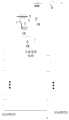
图1是本发明的换流阀稳态运行试验装置拓扑结构图;Fig. 1 is the topology structure diagram of the steady-state operation test device of the converter valve of the present invention;
图2是本发明的并联谐振电路原理图;2 is a schematic diagram of a parallel resonant circuit of the present invention;
图3是本发明的半桥功率单元模块电路原理图;3 is a schematic circuit diagram of a half-bridge power unit module of the present invention;
图4是本发明的全桥功率单元模块电路原理图。FIG. 4 is a schematic circuit diagram of a full-bridge power unit module of the present invention.
具体实施方式Detailed ways
下面结合附图和具体实施方式对本发明的内容做进一步详细说明。The content of the present invention will be further described in detail below with reference to the accompanying drawings and specific embodiments.
实施例:Example:
如图1所示,一种柔性直流换流阀型式试验装置,包括第一试品阀段(或简称试品阀段1)、第二试品阀段(或简称试品阀段2)、变压模块电路、交流谐振电路,所述变压模块电路包括变压器T,所述变压器T具有原边绕组和副边绕组,所述原边绕组与开关K01、交流试验电源S串接,所述副边绕组与第一电容器C1、切换开关K02串联后,再与所述交流谐振电路并联,所述第一试品阀段和所述第二试品阀段一端相连接并接地,另外一端分别连接至所述交流谐振电路两端,所述交流谐振电路用于给所述第一试品阀段和所述第二试品阀段提供直流电流通路并阻断交流电流分量,所述第一试品阀段和所述第二试品阀段包括若干串联的半桥功率单元或全桥功率单元。As shown in Figure 1, a flexible DC converter valve type test device includes a first test valve section (or test valve section 1 for short), a second test valve section (or
如图2所示,交流谐振电路由第二电抗器L2和第二电容器C2并联组成,谐振频率为基频,可取L2为3.4mH,C2为3mF,为试品阀段1和试品阀段2提供直流电流通路,阻断交流电流分量。As shown in Figure 2, the AC resonant circuit is composed of the second reactor L2 and the second capacitor C2 in parallel. The resonant frequency is the fundamental frequency, and L2 is preferably 3.4mH and C2 is 3mF, which are the test valve section 1 and the test valve section. 2 Provide a direct current path and block the alternating current component.
变压器T可以采用调压器,调压器一次绕组经开关K01与交流电源连接,在试验过程中通过调压器的缓慢调压对试验电路进行充电。变压器T二次绕组(即副边绕组)为3个分接头,第一分接头为高压端子,输出电压较高,额定电流较小。第二分接头为低压端子,输出额定电压较低,额定电流较大。第三分接头为公共端。第三分接头与第一电容器C1一端连接,第1或第2分接头与切换开关K02一端连接。The transformer T can use a voltage regulator. The primary winding of the voltage regulator is connected to the AC power supply through the switch K01, and the test circuit is charged through the slow voltage regulation of the voltage regulator during the test. The secondary winding (ie, the secondary winding) of the transformer T has 3 taps, the first tap is a high-voltage terminal, the output voltage is high, and the rated current is small. The second tap is a low-voltage terminal with a lower output rated voltage and a higher rated current. The third tap is the common terminal. The third tap is connected to one end of the first capacitor C1, and the first or second tap is connected to one end of the changeover switch K02.
如图3所示,所述半桥功率单元主回路包括IGBT1和IGBT2及其反并联二极管D1和D2、电容器CH、放电电阻RH、旁路晶闸管TrH组成;以半桥拓扑结构连接。通过控制触发上下IGBT的导通和关断来控制功率单元的投入和切除。As shown in FIG. 3 , the main circuit of the half-bridge power unit includes IGBT1 and IGBT2 and their anti-parallel diodes D1 and D2, capacitorCH , discharge resistorRH , and bypass thyristorTrH ; connected in a half-bridge topology. The turn-on and turn-off of the power unit is controlled by controlling the turn-on and turn-off of the upper and lower IGBTs.
如图4所示,所述全桥功率单元主回路包括IGBT1、IGBT2、IGBT3和IGBT4及其反并联二极管D1~D4、电容器CF、放电电阻RF、旁路晶闸管TrF组成;以全桥拓扑结构连接。通过控制触发IGBT的导通和关断来控制功率单元的投入和切除。As shown in Figure 4, the main circuit of the full-bridge power unit includes IGBT1, IGBT2,IGBT3 and IGBT4 and their anti-parallel diodes D1-D4, capacitor CF, discharge resistorRF , and bypass thyristorTrF . Topological connections. The turn-on and turn-off of the power unit is controlled by controlling the turn-on and turn-off of the trigger IGBT.
一种柔性直流换流阀型式试验装置的试验方法,包括:A test method for a flexible DC converter valve type test device, comprising:
步骤1:预充电,将切换开关K02与调压器T的副边绕组的高压端子连接。具体地,预充电,在试品阀段1和试品阀段2中的功率单元电容电压还没有建立起来时,需要对它们进行充电,首先使切换开关K02与调压器T二次绕组(即副边绕组)第1分接头连接,使试品阀段1和试品阀段2能够获得较高的预充电电压,保证功率单元能够稳定工作。Step 1: Pre-charge, connect the switch K02 to the high voltage terminal of the secondary winding of the voltage regulator T. Specifically, for pre-charging, when the capacitor voltage of the power unit in the test valve section 1 and the
步骤2:切换至补能回路,待第一试品阀段和第二试品阀段中功率单元充电至设定电压数值且充电电流接近0时,将切换开关K02切换至低压端子。具体地,切换至补能回路,待试品阀段中功率单元充电至设定数值,充电电流接近0时,将切换开关K02切换至于变压器T的第2分接头连接。分接头2输出电压较低,可通过较大的试品阀段运行试验电流,并能够补充阀段运行试验过程中损耗的能量。Step 2: Switch to the energy compensation circuit. When the power units in the first and second sample valve sections are charged to the set voltage value and the charging current is close to 0, switch the switch K02 to the low-voltage terminal. Specifically, switch to the energy supplement circuit, the power unit in the valve section of the test object is charged to the set value, and when the charging current is close to 0, the switch K02 is switched to the second tap of the transformer T to connect. The output voltage of
步骤3:解锁试品阀段,切换开关切换至补能回路后,解锁试品阀段,通过调节第一试品阀段和第二试品阀段的调制信号间的相位和幅值,以产生试品阀段所需的交流电流和直流电流分量。具体地,解锁试品阀段,切换开关切换至补能回路后,解锁试品阀段,通过调节两个试品阀段调制信号间的相位和幅值,可在试品阀段间产生所需的交流电流和直流电流分量。其中谐振回路对基波阻抗极大,仅通过直流电流分量,变压器二次侧低压绕组和第一电容器C1组成的串联回路通过基频交流电流,由于该回路中电容器C1的存在,可以阻断直流分量,避免变压器T饱和。Step 3: Unlock the test sample valve section, after the switch is switched to the energy replenishing circuit, unlock the test sample valve section, and adjust the phase and amplitude between the modulation signals of the first test sample valve section and the second test sample valve section to achieve The AC and DC current components required to generate the test valve section. Specifically, unlock the test valve section, switch the switch to the energy-supplying circuit, unlock the test valve section, and adjust the phase and amplitude of the modulation signals between the two test valve sections, so that the difference between the test valve sections can be generated. required alternating current and direct current components. Among them, the resonance circuit has a very large impedance to the fundamental wave. Only through the DC current component, the series circuit composed of the low-voltage winding on the secondary side of the transformer and the first capacitor C1 passes the fundamental frequency AC current. Due to the existence of the capacitor C1 in this circuit, the DC current can be blocked. component to avoid transformer T saturation.
步骤4:稳态运行,试品阀段解锁后(即换流阀解锁后),通过改变试品阀段1和试品阀段2的调制信号控制两个试品阀间的环流,典型的试验情况下,试品阀段1和试品阀段2的调制波都给定为正弦信号,两者幅值、频率相等,相差一个小的角度;因此,试品阀段1和试品阀段2中间的谐振回路和第一电容C1与变压器二次绕组(即副边绕组)的串联回路,将承受两者电压的差值,因而产生一个相同频率的正弦环流。正弦环流将流过阻抗相对较小的第一电容C1与变压器二次绕组(即副边绕组)的串联支路。而两个试品阀段之间微小的电容电压差将导致交流谐振回路流过直流分量,正弦环流和直流分量合成了所需的试验电流,流过两个试品阀段。Step 4: Steady-state operation, after the test valve section is unlocked (that is, after the converter valve is unlocked), the circulation between the two test valve sections is controlled by changing the modulation signal of the test valve section 1 and the
进一步地,预充电包括以下具体步骤:Further, precharging includes the following specific steps:
第一步:开始时,将变压器T或调压器T1调到输出为零电压,闭合开关K01;The first step: at the beginning, adjust the transformer T or the voltage regulator T1 to output zero voltage, and close the switch K01;
第二步:然后缓慢上升变压器T或调压器T1输出电压,因为试品阀段1和试品阀段2分别连接在调压器T二次绕组(即副边绕组)的两端。对于半桥功率单元组成的试品阀段,在交流电源的正半波时对试品阀段1充电,而交流电源的负半波时对试品阀段2充电;对于全桥功率单元组成的试品阀段,由于全桥单元在闭锁状态下相当于全桥整流结构,试品阀段在交流电源两个方向上均充电。Step 2: Then slowly increase the output voltage of the transformer T or the voltage regulator T1, because the test valve section 1 and the
第三步、等待调压器上升到规定电压,充电结束,这时试品阀段1和试品阀段2上的桥臂电容电压和都等于交流电源的峰值电压,可以将调压器T切换至低压绕组,开始试验。其中低压绕组输出电压较低,但能够通过较大额定电流,满足运行试验中补能需要。The third step is to wait for the voltage regulator to rise to the specified voltage, and the charging is over. At this time, the sum of the bridge arm capacitor voltages on the test valve section 1 and the
进一步地,所述稳态运行,在具体试验过程中,可控制试品阀段1和试品阀段2中任意一个阀段的调制信号为正弦信号,调节另一个试品阀段的调制信号的幅值和相位,使得试品阀段1、试品阀段2中流过电流的直流分量和交流分量满足实验目标需求,并保持试品阀段1和试品阀段2之间的电容电压平均值相等。Further, in the steady-state operation, during the specific test process, the modulation signal of any valve section in the test valve section 1 and the
上述实施例只是为了说明本发明的技术构思及特点,其目的是在于让本领域内的普通技术人员能够了解本发明的内容并据以实施,并不能以此限制本发明的保护范围。凡是根据本发明内容的实质所做出的等效的变化或修饰,都应涵盖在本发明的保护范围内。The above-mentioned embodiments are only to illustrate the technical concept and characteristics of the present invention, and the purpose thereof is to enable those of ordinary skill in the art to understand the content of the present invention and implement them accordingly, and not to limit the protection scope of the present invention. All equivalent changes or modifications made according to the essence of the present invention shall be included within the protection scope of the present invention.
Claims (8)
Priority Applications (1)
| Application Number | Priority Date | Filing Date | Title |
|---|---|---|---|
| CN202010372455.1ACN111551844B (en) | 2020-05-06 | 2020-05-06 | Flexible direct current converter valve type test device and method |
Applications Claiming Priority (1)
| Application Number | Priority Date | Filing Date | Title |
|---|---|---|---|
| CN202010372455.1ACN111551844B (en) | 2020-05-06 | 2020-05-06 | Flexible direct current converter valve type test device and method |
Publications (2)
| Publication Number | Publication Date |
|---|---|
| CN111551844Atrue CN111551844A (en) | 2020-08-18 |
| CN111551844B CN111551844B (en) | 2021-04-06 |
Family
ID=72004605
Family Applications (1)
| Application Number | Title | Priority Date | Filing Date |
|---|---|---|---|
| CN202010372455.1AActiveCN111551844B (en) | 2020-05-06 | 2020-05-06 | Flexible direct current converter valve type test device and method |
Country Status (1)
| Country | Link |
|---|---|
| CN (1) | CN111551844B (en) |
Cited By (9)
| Publication number | Priority date | Publication date | Assignee | Title |
|---|---|---|---|---|
| CN111884229A (en)* | 2020-08-19 | 2020-11-03 | 南方电网科学研究院有限责任公司 | Asynchronous and synchronous control method and system for back-to-back flexible direct current power transmission system |
| CN112269152A (en)* | 2020-10-29 | 2021-01-26 | 华北电力科学研究院有限责任公司 | Transformer and converter valve charging test circuit and method |
| CN113189424A (en)* | 2021-04-26 | 2021-07-30 | 中国南方电网有限责任公司超高压输电公司天生桥局 | Series resonance flexible direct current converter valve operation test topology and control method |
| CN113567107A (en)* | 2021-06-15 | 2021-10-29 | 南京南瑞继保电气有限公司 | Cascaded converter valve testing system and control method thereof |
| CN113884959A (en)* | 2021-09-06 | 2022-01-04 | 中国科学院合肥物质科学研究院 | Flat-top-wave-like pulse high-intensity magnetic field generating device and method |
| CN114167194A (en)* | 2022-02-11 | 2022-03-11 | 华北电力科学研究院有限责任公司 | Test device for flexible DC transmission voltage source converter valve |
| CN114167272A (en)* | 2021-12-03 | 2022-03-11 | 广东电网有限责任公司 | Flexible direct current converter valve steady-state operation test device and method |
| CN115774157A (en)* | 2021-09-07 | 2023-03-10 | 南京南瑞继保电气有限公司 | Low-frequency power transmission converter valve test system and test method thereof |
| CN117233556A (en)* | 2023-11-10 | 2023-12-15 | 西安高压电器研究院股份有限公司 | Overvoltage test system for high-voltage alternating-current capacitor |
Citations (11)
| Publication number | Priority date | Publication date | Assignee | Title |
|---|---|---|---|---|
| CN101706541A (en)* | 2009-12-04 | 2010-05-12 | 中国电力科学研究院 | Detection device for fault current experiment of direct-current transmission converter valve |
| CN102354203A (en)* | 2011-06-24 | 2012-02-15 | 中国电力科学研究院 | Combined test method of dynamic simulation device and engineering control system |
| CN204008998U (en)* | 2014-06-24 | 2014-12-10 | 国家电网公司 | The many level converter valve operating test system being formed by H bridge submodule |
| CN104965172A (en)* | 2015-07-28 | 2015-10-07 | 南京南瑞继保电气有限公司 | Converter valve operation test commutation angle adjusting device and method |
| CN106990309A (en)* | 2017-04-28 | 2017-07-28 | 荣信汇科电气技术有限责任公司 | A kind of converter valve Tests at Steady State device and method of use AC-testing supply |
| CN106997012A (en)* | 2017-04-28 | 2017-08-01 | 荣信汇科电气技术有限责任公司 | The converter valve Tests at Steady State device and method of bias voltage is undertaken using electric capacity |
| CN108471132A (en)* | 2018-03-29 | 2018-08-31 | 西安许继电力电子技术有限公司 | A kind of current conversion station carries out the startup method of DC side charging by dc circuit breaker |
| CN109283464A (en)* | 2018-10-18 | 2019-01-29 | 许继集团有限公司 | Thermal operation test device for thyristor converter valve |
| CN105634026B (en)* | 2015-10-16 | 2019-02-26 | 华北电力大学 | A grid-commutated converter structure based on an anti-parallel thyristor full-bridge sub-module converter |
| CN109905046A (en)* | 2019-01-23 | 2019-06-18 | 北京平高清大科技发展有限公司 | A test circuit for MMC converter |
| CN209911505U (en)* | 2019-04-03 | 2020-01-07 | 国网冀北电力有限公司电力科学研究院 | A device for detecting the internal electrical performance of the converter valve sub-module |
- 2020
- 2020-05-06CNCN202010372455.1Apatent/CN111551844B/enactiveActive
Patent Citations (11)
| Publication number | Priority date | Publication date | Assignee | Title |
|---|---|---|---|---|
| CN101706541A (en)* | 2009-12-04 | 2010-05-12 | 中国电力科学研究院 | Detection device for fault current experiment of direct-current transmission converter valve |
| CN102354203A (en)* | 2011-06-24 | 2012-02-15 | 中国电力科学研究院 | Combined test method of dynamic simulation device and engineering control system |
| CN204008998U (en)* | 2014-06-24 | 2014-12-10 | 国家电网公司 | The many level converter valve operating test system being formed by H bridge submodule |
| CN104965172A (en)* | 2015-07-28 | 2015-10-07 | 南京南瑞继保电气有限公司 | Converter valve operation test commutation angle adjusting device and method |
| CN105634026B (en)* | 2015-10-16 | 2019-02-26 | 华北电力大学 | A grid-commutated converter structure based on an anti-parallel thyristor full-bridge sub-module converter |
| CN106990309A (en)* | 2017-04-28 | 2017-07-28 | 荣信汇科电气技术有限责任公司 | A kind of converter valve Tests at Steady State device and method of use AC-testing supply |
| CN106997012A (en)* | 2017-04-28 | 2017-08-01 | 荣信汇科电气技术有限责任公司 | The converter valve Tests at Steady State device and method of bias voltage is undertaken using electric capacity |
| CN108471132A (en)* | 2018-03-29 | 2018-08-31 | 西安许继电力电子技术有限公司 | A kind of current conversion station carries out the startup method of DC side charging by dc circuit breaker |
| CN109283464A (en)* | 2018-10-18 | 2019-01-29 | 许继集团有限公司 | Thermal operation test device for thyristor converter valve |
| CN109905046A (en)* | 2019-01-23 | 2019-06-18 | 北京平高清大科技发展有限公司 | A test circuit for MMC converter |
| CN209911505U (en)* | 2019-04-03 | 2020-01-07 | 国网冀北电力有限公司电力科学研究院 | A device for detecting the internal electrical performance of the converter valve sub-module |
Non-Patent Citations (1)
| Title |
|---|
| 常忠廷等: "基于非对称电压的换流阀暂态低电压运行实验实现方法", 《智慧电力》* |
Cited By (13)
| Publication number | Priority date | Publication date | Assignee | Title |
|---|---|---|---|---|
| CN111884229A (en)* | 2020-08-19 | 2020-11-03 | 南方电网科学研究院有限责任公司 | Asynchronous and synchronous control method and system for back-to-back flexible direct current power transmission system |
| CN112269152A (en)* | 2020-10-29 | 2021-01-26 | 华北电力科学研究院有限责任公司 | Transformer and converter valve charging test circuit and method |
| CN113189424B (en)* | 2021-04-26 | 2022-09-06 | 中国南方电网有限责任公司超高压输电公司天生桥局 | Series resonance flexible direct current converter valve operation test topology and control method |
| CN113189424A (en)* | 2021-04-26 | 2021-07-30 | 中国南方电网有限责任公司超高压输电公司天生桥局 | Series resonance flexible direct current converter valve operation test topology and control method |
| CN113567107A (en)* | 2021-06-15 | 2021-10-29 | 南京南瑞继保电气有限公司 | Cascaded converter valve testing system and control method thereof |
| CN113884959A (en)* | 2021-09-06 | 2022-01-04 | 中国科学院合肥物质科学研究院 | Flat-top-wave-like pulse high-intensity magnetic field generating device and method |
| CN113884959B (en)* | 2021-09-06 | 2023-11-07 | 中国科学院合肥物质科学研究院 | A flat-top wave pulse strong magnetic field generating device and method |
| CN115774157A (en)* | 2021-09-07 | 2023-03-10 | 南京南瑞继保电气有限公司 | Low-frequency power transmission converter valve test system and test method thereof |
| CN114167272A (en)* | 2021-12-03 | 2022-03-11 | 广东电网有限责任公司 | Flexible direct current converter valve steady-state operation test device and method |
| CN114167272B (en)* | 2021-12-03 | 2024-04-12 | 广东电网有限责任公司 | Flexible direct current converter valve steady-state operation test device and method |
| CN114167194B (en)* | 2022-02-11 | 2022-05-06 | 华北电力科学研究院有限责任公司 | Testing device for converter valve of flexible direct-current power transmission voltage source |
| CN114167194A (en)* | 2022-02-11 | 2022-03-11 | 华北电力科学研究院有限责任公司 | Test device for flexible DC transmission voltage source converter valve |
| CN117233556A (en)* | 2023-11-10 | 2023-12-15 | 西安高压电器研究院股份有限公司 | Overvoltage test system for high-voltage alternating-current capacitor |
Also Published As
| Publication number | Publication date |
|---|---|
| CN111551844B (en) | 2021-04-06 |
Similar Documents
| Publication | Publication Date | Title |
|---|---|---|
| CN111551844B (en) | Flexible direct current converter valve type test device and method | |
| CN107196539B (en) | A zero-DC voltage fault ride-through control method for MMC in the state of bridge arm parameter asymmetry | |
| USRE37126E1 (en) | Multilevel cascade voltage source inverter with seperate DC sources | |
| US9007792B2 (en) | Arrangement for transmitting power between a DC power line and an AC power line | |
| CN107732954B (en) | A kind of voltage source converter unit online input control method and device | |
| CN109217687A (en) | Power distribution network electric power electric transformer and its control method based on MMC | |
| WO2012103951A2 (en) | Power electronic converter | |
| CN204835971U (en) | Multiport power electronic transformer | |
| CN111371336B (en) | Hybrid modular multilevel converter based on energy self-balancing circuit | |
| Fang et al. | Modulation and control method for bidirectional isolated AC/DC matrix based converter in hybrid AC/DC microgrid | |
| CN116646935A (en) | Series flexible switching converter supporting micro-grid full-automatic control and control method | |
| CN107370392A (en) | Towards the electric power electric transformer of mesohigh intelligent distribution network | |
| CN110943634B (en) | Energy type router and soft charging control method and system thereof | |
| CN118100259A (en) | Multi-port flexible interconnection device, AC/DC hybrid transmission system and AC substation | |
| CN113258776B (en) | High step-up ratio DC converter for large-scale offshore wind power DC transmission | |
| CN115333135A (en) | Control system of bipolar flexible direct current converter station | |
| CN112290574B (en) | A current collector suitable for DC collection and its control method | |
| CN105429472B (en) | A kind of star-angle type rectifier type high power DC booster converter and its control method | |
| Taghvaie et al. | A multilevel solid-State transformer-based grid-connected solar photovoltaic systems | |
| CN116722569A (en) | An energy storage device and control method based on half-bridge and full-bridge hybrid MMC | |
| CN113452276B (en) | CCC-PHC type hybrid cascade direct current converter, rectifying station, inverter station and power transmission system | |
| CN105553275B (en) | Six phase contravariant high power DC booster converters of one kind and its control method | |
| US20240146066A1 (en) | Power grid stabilization system | |
| Xu et al. | A STATCOM based on cascade multilevel inverter with phase-shift SPWM | |
| Missula | Single-phase Five-level Boost Inverter for Stand-alone PV Applications |
Legal Events
| Date | Code | Title | Description |
|---|---|---|---|
| PB01 | Publication | ||
| PB01 | Publication | ||
| SE01 | Entry into force of request for substantive examination | ||
| SE01 | Entry into force of request for substantive examination | ||
| GR01 | Patent grant | ||
| GR01 | Patent grant | ||
| CP03 | Change of name, title or address | Address after:510663 maintenance and test center, building 2, 223, science Avenue, Science City, Luogang District, Guangzhou City, Guangdong Province Patentee after:China Southern Power Grid Corporation Ultra High Voltage Transmission Company Electric Power Research Institute Country or region after:China Address before:510663 maintenance and test center, building 2, 223, science Avenue, Science City, Luogang District, Guangzhou City, Guangdong Province Patentee before:MAINTENANCE & TEST CENTRE, CSG EHV POWER TRANSMISSION Co. Country or region before:China | |
| CP03 | Change of name, title or address |