CN111550242A - Mining machine cutting arm suitable for thin seam mining - Google Patents
Mining machine cutting arm suitable for thin seam miningDownload PDFInfo
- Publication number
- CN111550242A CN111550242ACN202010515159.2ACN202010515159ACN111550242ACN 111550242 ACN111550242 ACN 111550242ACN 202010515159 ACN202010515159 ACN 202010515159ACN 111550242 ACN111550242 ACN 111550242A
- Authority
- CN
- China
- Prior art keywords
- arm
- split
- pin hole
- gear
- mining
- Prior art date
- Legal status (The legal status is an assumption and is not a legal conclusion. Google has not performed a legal analysis and makes no representation as to the accuracy of the status listed.)
- Granted
Links
Images


Classifications
- E—FIXED CONSTRUCTIONS
- E21—EARTH OR ROCK DRILLING; MINING
- E21C—MINING OR QUARRYING
- E21C25/00—Cutting machines, i.e. for making slits approximately parallel or perpendicular to the seam
- E21C25/06—Machines slitting solely by one or more cutting rods or cutting drums which rotate, move through the seam, and may or may not reciprocate
- E21C25/08—Mountings for the rods or drums
- E—FIXED CONSTRUCTIONS
- E21—EARTH OR ROCK DRILLING; MINING
- E21C—MINING OR QUARRYING
- E21C31/00—Driving means incorporated in machines for slitting or completely freeing the mineral from the seam
- E21C31/02—Driving means incorporated in machines for slitting or completely freeing the mineral from the seam for cutting or breaking-down devices
- E—FIXED CONSTRUCTIONS
- E21—EARTH OR ROCK DRILLING; MINING
- E21C—MINING OR QUARRYING
- E21C35/00—Details of, or accessories for, machines for slitting or completely freeing the mineral from the seam, not provided for in groups E21C25/00 - E21C33/00, E21C37/00 or E21C39/00
- E21C35/20—General features of equipment for removal of chippings, e.g. for loading on conveyor
- F—MECHANICAL ENGINEERING; LIGHTING; HEATING; WEAPONS; BLASTING
- F16—ENGINEERING ELEMENTS AND UNITS; GENERAL MEASURES FOR PRODUCING AND MAINTAINING EFFECTIVE FUNCTIONING OF MACHINES OR INSTALLATIONS; THERMAL INSULATION IN GENERAL
- F16H—GEARING
- F16H1/00—Toothed gearings for conveying rotary motion
- F16H1/28—Toothed gearings for conveying rotary motion with gears having orbital motion
Landscapes
- Engineering & Computer Science (AREA)
- Mining & Mineral Resources (AREA)
- Mechanical Engineering (AREA)
- Life Sciences & Earth Sciences (AREA)
- General Life Sciences & Earth Sciences (AREA)
- Geochemistry & Mineralogy (AREA)
- Geology (AREA)
- General Engineering & Computer Science (AREA)
- Retarders (AREA)
- Drilling And Exploitation, And Mining Machines And Methods (AREA)
Abstract
Description
Translated fromChinese技术领域technical field
本发明涉及一种适用于薄矿层开采的采矿机截割臂,尤其适用于薄矿层及以上厚度矿层开采的开采范围较大、地质条件比较复杂的矿岩工作面,属于井工采矿机械技术领域。The invention relates to a mining machine cutting arm suitable for thin ore seam mining, especially suitable for thin ore seam and above thick ore seam mining with large mining range and complex geological conditions ore rock face, belonging to the technical field of underground mining machinery .
背景技术Background technique
对于铝土薄矿层的开采,往往地质条件复杂,不仅土状矿层与岩状废料共存,而且矿层薄厚变化大,因此不仅需要大的截割力,而且需要采矿机矮型化同时又能适应厚矿层的开采。按照常规的设计规则,通常较大的截割力意味着需要配备较大功率的截割电机、上下臂厚较厚的截割臂和直径较大的滚筒,采矿机矮型化则需要截割臂相对于输送装置有足够的下切量、相对于支架顶梁有足够的挑顶量,然而较厚的截割臂往往导致下切量和挑顶量不足,严重影响开采,因此需要解决重型、宽采高范围的薄矿层采矿机的上述结构布置方面的问题。For the mining of thin bauxite layers, the geological conditions are often complex. Not only the soil layer and rocky waste coexist, but also the thickness of the layer varies greatly. Therefore, not only a large cutting force is required, but also the mining machine needs to be low-profile and adaptable to thick Mining of ore seams. According to the conventional design rules, usually a larger cutting force means that a larger power cutting motor, a cutting arm with thick upper and lower arms and a drum with a larger diameter are required. The arm has enough undercutting amount relative to the conveying device and enough topping amount relative to the support top beam. However, the thicker cutting arm often leads to insufficient undercutting amount and topping amount, which seriously affects the mining. Therefore, it is necessary to solve the problem of heavy and wide. The above-mentioned problems in the structural arrangement of the thin seam mining machine in the mining height range.
发明内容SUMMARY OF THE INVENTION
本发明旨在提供一种适用于薄矿层开采的采矿机截割臂,能在提供较大截割力的同时,使采矿机保持足够的下切量和挑顶量,使矮机身大功率采矿机适用于开采范围大、地质条件复杂的矿岩工作面的开采。The invention aims to provide a cutting arm of a mining machine suitable for mining thin ore layers, which can provide a large cutting force while maintaining a sufficient amount of undercutting and overhanging of the mining machine, enabling the mining machine with a short body to mine with high power. The machine is suitable for the mining of rock face with large mining range and complex geological conditions.
本发明的主要技术方案有:The main technical solutions of the present invention include:
一种适用于薄矿层开采的采矿机截割臂,包括臂架、截割电机、传动系统、离合机构和小直径滚筒,臂架的近端设有用于与采矿机机身连接的安装接口结构,当臂架安装到采矿机机身上时,臂架的远端悬伸并远离机身,所述臂架包括直臂部和自直臂部的近端向后方凸出的电机安装部以及自直臂部的远端向前方凸出的滚筒安装部,所述截割电机、传动系统和离合机构均设置在臂架的内腔,所述截割电机位于所述电机安装部,所述传动系统包括按照传动方向依次连接的高速级行星机构、前定轴减速传动机构和后定轴减速传动机构,所述后定轴减速传动机构的末级传动采用齿轮轴,所述高速级行星机构和前定轴减速传动机构设置于所述直臂部的近段,所述齿轮轴旋转支撑于滚筒安装部,所述齿轮轴的齿轮所在端以及所述后定轴减速传动机构的其他各级传动设置于所述直臂部的中远段,所述小直径滚筒套在滚筒安装部之外并与所述齿轮轴的非齿轮所在端同轴固定连接,所述高速级行星机构同轴设置在所述截割电机的前方,高速级行星机构的输入端通过所述离合机构与所述截割电机的输出端连接或脱开连接,所述直臂部的远端的顶面和底面分别设有上斜平面和下斜平面,倾斜方向是使所述直臂部越靠近远端上下厚度越薄的方向,使直臂部的远端形成上下厚度较薄的局部薄条状结构。A mining machine cutting arm suitable for thin ore seam mining, including a boom, a cutting motor, a transmission system, a clutch mechanism and a small-diameter drum, the proximal end of the boom is provided with an installation interface structure for connecting with a mining machine body , when the boom is mounted on the body of the mining machine, the distal end of the boom is suspended and away from the fuselage, the boom includes a straight arm part and a motor mounting part protruding rearward from the proximal end of the straight arm part and The drum mounting portion protruding forward from the distal end of the straight arm portion, the cutting motor, the transmission system and the clutch mechanism are all arranged in the inner cavity of the arm frame, the cutting motor is located in the motor mounting portion, the The transmission system includes a high-speed planetary mechanism, a front fixed-axis deceleration transmission mechanism and a rear fixed-axis deceleration transmission mechanism connected in sequence according to the transmission direction. The final transmission of the rear fixed-axis deceleration transmission mechanism adopts a gear shaft, and the high-speed planetary mechanism The gear shaft and the front fixed shaft deceleration transmission mechanism are arranged in the near section of the straight arm portion, the gear shaft is rotatably supported on the drum installation portion, the end of the gear shaft where the gear is located and the other levels of the rear fixed shaft deceleration transmission mechanism The transmission is arranged in the middle and distal sections of the straight arm portion, the small-diameter roller is sleeved outside the roller mounting portion and is coaxially fixedly connected with the non-gear end of the gear shaft, and the high-speed planetary mechanism is coaxially arranged at the end of the gear shaft. In front of the cutting motor, the input end of the high-speed planetary mechanism is connected or disconnected from the output end of the cutting motor through the clutch mechanism. There are an upper inclined plane and a lower inclined plane, and the inclined direction is the direction in which the upper and lower thickness of the straight arm portion becomes thinner as it approaches the distal end, so that the distal end of the straight arm portion forms a local thin strip structure with thinner upper and lower thickness.
所述高速级行星机构包括高速级太阳轮、高速级行星轮、高速级行星架和高速级内齿圈,所述高速级内齿圈周向固定在所述臂架上,所述高速级太阳轮为首级传动的输入端The high-speed stage planetary mechanism includes a high-speed stage sun gear, a high-speed stage planetary gear, a high-speed stage planet carrier and a high-speed stage ring gear, the high-speed stage ring gear is circumferentially fixed on the arm frame, and the high-speed stage sun gear The wheel is the input end of the first stage drive
所述前定轴减速传动机构包括依次外啮合传动连接的前定轴减速小齿轮、前定轴减速中间齿轮和前定轴减速大齿轮,所述前定轴减速小齿轮旋转支撑在臂架上,所述高速级行星架与所述前定轴减速小齿轮分别从两端套在一个高速级连接轴上,并与所述高速级连接轴同轴花键连接。The front fixed axis deceleration transmission mechanism includes a front fixed axis deceleration pinion, a front fixed axis deceleration intermediate gear and a front fixed axis deceleration gear that are sequentially externally meshed and connected, and the front fixed axis deceleration pinion is rotatably supported on the arm frame. The high-speed stage planet carrier and the front fixed shaft reduction pinion are respectively sleeved on a high-speed stage connecting shaft from both ends, and are connected with the high-speed stage connecting shaft coaxially with splines.
所述后定轴减速传动机构还包括后定轴减速前齿轮和后定轴减速中间齿轮,后定轴减速前齿轮、后定轴减速中间齿轮和所述齿轮轴依次外啮合传动连接。The rear fixed axis deceleration transmission mechanism also includes a rear fixed axis deceleration front gear and a rear fixed axis deceleration intermediate gear.
所述截割电机优选采用多极电机,极数可以为6、8、10或12。The cutting motor is preferably a multi-pole motor, and the number of poles can be 6, 8, 10 or 12.
所述臂架为分体式结构,包括分体臂和分体过渡座,所述安装接口结构设置在分体过渡座上,所述分体臂和分体过渡座之间通过连接件连接紧固。The arm frame is a split structure, including a split arm and a split transition seat, the installation interface structure is arranged on the split transition seat, and the split arm and the split transition seat are connected and fastened by connecting pieces. .
所述分体过渡座与分体臂相贴合的面上分散设有多个过渡座销孔组,每个过渡座销孔组包括一个过渡座前销孔和一个过渡座后销孔,所述分体臂与分体过渡座相贴合的面上分散设有多个与过渡座销孔组一一对应的分体臂销孔组,每个分体臂销孔组包括一个分体臂前销孔和一个分体臂后销孔,所有销孔的直径相等,所述分体过渡座与分体臂通过每个过渡座销孔组的一个销孔与对应的分体臂销孔组的一个销孔同时与一个连接销配合实现前后上下方向定位,所述分体过渡座与分体臂之间通过螺栓、螺母紧固。A plurality of transition seat pin hole groups are scattered on the surface where the split transition seat and the split arm fit, and each transition seat pin hole group includes a front pin hole of the transition seat and a rear pin hole of the transition seat. A plurality of split arm pin hole groups corresponding to the transition seat pin hole groups one-to-one are scattered on the surface where the split arm and the split transition seat fit, and each split arm pin hole group includes a split arm The front pin hole and the rear pin hole of a split arm, all the pin holes have the same diameter, the split transition seat and the split arm pass through one pin hole of each transition seat pin hole group and the corresponding split arm pin hole group One of the pin holes of the device is matched with a connecting pin at the same time to realize the positioning in the front and rear up and down directions, and the split transition seat and the split arm are fastened by bolts and nuts.
所述过渡座前销孔和分体臂前销孔同时与一个连接销配合实现定位,或者所述过渡座后销孔和分体臂后销孔同时与一个连接销配合实现定位,当过渡座前、后销孔的中心距大于分体臂前、后销孔的中心距时,所述过渡座后销孔和分体臂后销孔同时与一个连接销配合的情况下分体臂的前端面与分体过渡座平齐,当过渡座前、后销孔的中心距小于分体臂前、后销孔的中心距时,所述过渡座前销孔和分体臂前销孔同时与一个连接销配合的情况下分体臂的前端面与分体过渡座平齐。The front pin hole of the transition seat and the front pin hole of the split arm cooperate with a connecting pin at the same time to achieve positioning, or the rear pin hole of the transition seat and the rear pin hole of the split arm cooperate with a connecting pin to achieve positioning at the same time. When the center distance of the front and rear pin holes is greater than the center distance of the front and rear pin holes of the split arm, the front end of the split arm under the condition that the rear pin hole of the transition seat and the rear pin hole of the split arm are matched with one connecting pin at the same time The surface is flush with the split transition seat. When the center distance of the front and rear pin holes of the transition seat is less than the center distance of the front and rear pin holes of the split arm, the front pin hole of the transition seat and the front pin hole of the split arm are at the same time as The front end face of the split arm is flush with the split transition seat when a connecting pin is fitted.
所述分体过渡座上还设有多个螺栓孔,所述螺栓孔与所述过渡座销孔组一一对应,所述分体臂上设有多个腰型槽和多个螺母槽,所述腰型槽和螺母槽与所述螺栓孔一一对应,通过向螺栓孔和与之相对应的腰型槽内穿螺栓并用螺母槽内的方螺母锁紧实现分体过渡座与分体臂的紧固连接,过渡座前、后销孔的中心距与分体臂前、后销孔的中心距的差值不大于所述腰型槽的长度与宽度的差值。The split transition seat is also provided with a plurality of bolt holes, the bolt holes correspond to the transition seat pin hole groups one-to-one, and the split arm is provided with a plurality of waist-shaped grooves and a plurality of nut grooves, The waist-shaped grooves and the nut grooves correspond to the bolt holes one by one, and the split transition seat and the split body are realized by threading bolts into the bolt holes and the corresponding waist-shaped grooves and locking them with the square nuts in the nut grooves. For the tight connection of the arms, the difference between the center distance of the front and rear pin holes of the transition seat and the center distance of the front and rear pin holes of the split arm is not greater than the difference between the length and width of the waist-shaped groove.
本发明的有益效果是:The beneficial effects of the present invention are:
所述臂架的直臂部的远端的顶面和底面分别设有上斜平面和下斜平面,使直臂部越靠近远端的上下厚度越小,使臂架的远端形成具有上下厚度较小的局部薄条状结构,为小直径滚筒相对支架前梁与输送机铲板顶面分别具有大的挑顶量与下切量提供了保证。The top surface and bottom surface of the distal end of the straight arm portion of the boom are respectively provided with an upper inclined plane and a lower inclined plane, so that the upper and lower thicknesses of the straight arm portion are smaller as the straight arm portion is closer to the distal end, so that the distal end of the boom is formed with an upper and lower plane. The local thin strip structure with small thickness ensures that the small-diameter roller has a large amount of overhang and undercut respectively relative to the front beam of the bracket and the top surface of the conveyor shovel.
本发明的传动系统前段设置行星机构与前定轴减速传动机构,后段设置后定轴减速传动机构,进行多级减速,为减小末级传动的尺寸特别是径向尺寸提供条件,因此滚筒安装部的直径可以很小,因此可以配套很小直径的滚筒,不仅能适应较宽的采高范围,还为获得滚筒相对支架与输送机分别具有更大的挑顶量与下切量提供根本保证。The front section of the transmission system of the present invention is provided with a planetary mechanism and a front fixed-axis deceleration transmission mechanism, and the rear section is provided with a rear fixed-axis deceleration transmission mechanism to perform multi-stage deceleration, which provides conditions for reducing the size of the final stage transmission, especially the radial size. Therefore, the roller The diameter of the installation part can be very small, so it can be matched with a small-diameter roller, which can not only adapt to a wide range of mining heights, but also provide a fundamental guarantee for the roller to have a larger amount of topping and undercutting relative to the bracket and the conveyor, respectively. .
本发明采用多极的截割电机,再配合上述传动系统,可使截割臂的结构布设更灵活。The present invention adopts a multi-pole cutting motor and cooperates with the above-mentioned transmission system, so that the structure and arrangement of the cutting arm can be more flexible.
由于所述臂架的远端采用局部薄条状结构,矿料更容易自顶部跨越臂架进入输送机槽,改善了小直径滚筒下直臂架结构的装料效果。Since the distal end of the boom adopts a local thin strip structure, it is easier for the ore to cross the boom from the top to enter the conveyor trough, which improves the charging effect of the straight boom structure under the small-diameter roller.
由于分体臂相对分体过渡架具有水平方向上前后不同安装位置的可选择性,可提供臂架与输送机槽帮的更大的安全间隙,便于根据工作面实际条件进行相应调整,从而提高适应性。Since the split arm relative to the split transition frame has different installation positions in the horizontal direction, it can provide a larger safety gap between the arm frame and the conveyor trough, which is easy to adjust according to the actual conditions of the working surface, thereby improving adaptability.
附图说明Description of drawings
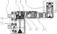
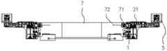
图1为本发明的一个实施例的主视图(右侧截割臂);Figure 1 is a front view (right cutting arm) of an embodiment of the present invention;
图2为图1的水平剖视图;Fig. 2 is the horizontal sectional view of Fig. 1;
图3为图1所示实施例下摆状态图;FIG. 3 is a state diagram of the hem of the embodiment shown in FIG. 1;
图4为图1所示实施例上摆状态图;FIG. 4 is a top-swing state diagram of the embodiment shown in FIG. 1;
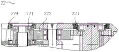
图5为所述前定轴减速传动机构的局部剖视图;FIG. 5 is a partial cross-sectional view of the front fixed shaft deceleration transmission mechanism;
图6为所述高速级行星机构的局部剖视图;6 is a partial cross-sectional view of the high-speed planetary mechanism;
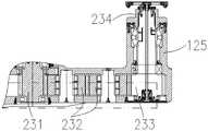
图7为所述后定轴减速传动机构的局部剖视图;7 is a partial cross-sectional view of the rear fixed-axis deceleration transmission mechanism;
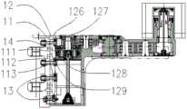
图8为本发明的分体臂的主视图(右侧截割臂);FIG. 8 is a front view of the split arm of the present invention (right cutting arm);
图9为本发明的分体过渡架的主视图(右侧截割臂);9 is a front view of the split transition frame of the present invention (right cutting arm);
图10为本发明相对支架、输送机的极限位置的断面图;10 is a cross-sectional view of the limit position relative to the bracket and the conveyor of the present invention;
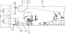
图11为安装有本发明的截割臂的采矿机的主视图;Figure 11 is a front view of a mining machine fitted with a cutting arm of the present invention;
图12为安装有本发明的截割臂的采矿机的俯视图;Figure 12 is a top view of a mining machine fitted with a cutting arm of the present invention;
图13为本发明的臂架的另一连接位置示意图。FIG. 13 is a schematic diagram of another connection position of the boom of the present invention.
附图标记:Reference number:
1.臂架;11.分体过渡座;111.过渡座前销孔;112.过渡座后销孔;113.螺栓孔;12.分体臂;121.上斜平面和下斜平面;125.滚筒安装部;126.腰型槽;127.螺母槽;128.分体臂前销孔;129.分体臂后销孔;13.连接件;14.连接销;1. Boom; 11. Split transition seat; 111. Front pin hole of transition seat; 112. Rear pin hole of transition seat; 113. Bolt hole; 12. Split arm; 121. Upper inclined plane and lower inclined plane; 125 .Roller installation part; 126. Waist groove; 127. Nut groove; 128. Front pin hole of split arm; 129. Rear pin hole of split arm; 13. Connecting piece; 14. Connecting pin;
21.高速级行星机构;211.高速级太阳轮;212.高速级行星轮;213.高速级内齿圈;2131.卡槽;214.高速级轴承;215.高速级销;216.高速级行星架;217.高速级连接轴;22.前定轴减速传动机构;221.前定轴减速小齿轮;222.前定轴减速中间齿轮;223.前定轴减速大齿轮;224.前定轴减速轴承座;23.后定轴减速传动机构;231.后定轴减速前齿轮;232.后定轴减速中间齿轮;233.齿轮轴;234.滚筒连接套;21. High-speed planetary mechanism; 211. High-speed sun gear; 212. High-speed planetary gear; 213. High-speed ring gear; 2131. Card slot; 214. High-speed bearing; 215. High-speed pin; 216. High-speed Planet carrier; 217. High-speed connecting shaft; 22. Front fixed shaft reduction gear; 221. Front fixed shaft reduction pinion; 222. Front fixed shaft reduction intermediate gear; 223. Front fixed shaft reduction gear; 224. Front fixed Shaft reduction bearing seat; 23. Rear fixed shaft reduction transmission mechanism; 231. Rear fixed shaft reduction front gear; 232. Rear fixed shaft reduction intermediate gear; 233. Gear shaft; 234. Roller connecting sleeve;
3.截割电机;3. Cutting motor;
4.离合机构;41.扭矩轴;4. Clutch mechanism; 41. Torque shaft;
5.小直径滚筒;5. Small diameter roller;
7.机身;71.截割臂连接件;72.截割臂油缸;7. Body; 71. Cutting arm connecting piece; 72. Cutting arm cylinder;
8.支架;81.支架顶面;82.支架前梁底面;8. The bracket; 81. The top surface of the bracket; 82. The bottom surface of the front beam of the bracket;
9.输送机;91.输送机底面;92.输送机铲板顶面;9. Conveyor; 91. Bottom surface of conveyor; 92. Top surface of conveyor shovel;
A.下切量;B.挑顶量;C.臂架偏置量。A. Undercut amount; B. Overhang amount; C. Boom offset.
具体实施方式Detailed ways
本发明公开了一种适用于薄矿层开采的采矿机截割臂,如图1-13所示,包括臂架1、截割电机3、传动系统、离合机构4和小直径滚筒5。臂架1通过截割臂连接件71和截割臂油缸72连接在采矿机机身7上。本文中根据臂架安装到采矿机机身7上时距离机身远近的不同对臂架各部位进行命名。臂架的近端设有用于与采矿机机身连接的安装接口结构,例如连接耳座。臂架的远端悬伸并远离机身。所述臂架包括直臂部和自直臂部的近端向后方凸出的电机安装部以及自直臂部的远端向前方凸出的滚筒安装部125。所述截割电机、传动系统和离合机构均设置在臂架的内腔。所述截割电机3位于所述电机安装部。所述传动系统包括按照传动方向依次连接的高速级行星机构21、前定轴减速传动机构22和后定轴减速传动机构23。所述后定轴减速传动机构的末级传动采用齿轮轴233。所述高速级行星机构和前定轴减速传动机构设置于所述直臂部的近段,所述齿轮轴旋转支撑于滚筒安装部,所述齿轮轴的齿轮所在端即后端以及所述后定轴减速传动机构的其他各级传动设置于所述直臂部的中远段。所述小直径滚筒5套在滚筒安装部之外并通过滚筒连接套234与所述齿轮轴的非齿轮所在端即前端同轴固定连接。滚筒连接套234位于所述齿轮轴的前方。所述高速级行星机构同轴设置在所述截割电机的前方,高速级行星机构的输入端通过所述离合机构与所述截割电机的输出端连接或脱开连接。所述直臂部的远端的顶面和底面分别设有上斜平面和下斜平面121(此处的倾斜可以是相对直臂部的近段的相互平行的顶面和底面而言的,也可以是相对传动系统各级轴线所在的平面而言的),倾斜方向是使所述直臂部越靠近远端上下厚度越薄的方向,使直臂部的远端形成上下厚度较薄的局部薄条状结构。截割电机3将动力通过离合机构4经过传动系统减速后传递给小直径滚筒5输出。在薄矿层开采中,直臂部在上摆与下摆极限状态时,上斜平面和下斜平面可以分别达到与支架8的支架前梁底面82和输送机9的输送机铲板顶面92接近平行的位置,由此分别获得小直径滚筒5的最大的挑顶量B(滚筒最高点高于支架顶面81的距离)与下切量A(滚筒最低点低于输送机底面91的距离)。The invention discloses a mining machine cutting arm suitable for thin ore seam mining, as shown in Figs. The
由于传动系统的首级传动采用了行星机构,不仅其本身体积小、重量轻,而且由于其承载力大,转速比大,因此在不改变截割臂的动力输出的情况下配套的下游其它各级传动以及滚筒的尺寸都可以大幅减小,因此有利于臂架整体尺寸的缩小以及臂架远端相比近端尺寸的进一步缩小,因此能使采矿机在提供大的截割力的同时,保持足够的下切量和挑顶量,使得相应采矿机适用于采高范围大、地质条件复杂的矿岩工作面的开采。Because the first-stage transmission of the transmission system adopts a planetary mechanism, it is not only small in size and light in weight, but also because of its large bearing capacity and large rotational speed ratio, so the other downstream supporting parts can be matched without changing the power output of the cutting arm. The size of the stage drive and the drum can be greatly reduced, which is conducive to the reduction of the overall size of the boom and the further reduction of the size of the distal end of the boom compared to the proximal end, so that the mining machine can provide a large cutting force while reducing Sufficient undercut and overhang are maintained, so that the corresponding mining machine is suitable for the mining of rock face with large mining height range and complex geological conditions.
由于传动系统的末级传动采用齿轮轴输出结构,直径较小,因此臂架的滚筒安装部125直径也较小,可配套很小直径的滚筒。同时直臂部的远端设置上下厚度较薄的局部薄条状结构,使得本发明的截割臂不仅能够配套小直径滚筒,而且小直径滚筒相对支架与输送机可以分别具有大的挑顶量与下切量;不仅保证高品位薄矿层的开采,而且提高了对复杂工作面开采的适应性。Since the final stage drive of the transmission system adopts a gear shaft output structure and has a small diameter, the diameter of the
由于设置所述局部薄条状结构,矿料更容易自顶部跨越臂架进入输送机槽,由此改善小直径滚筒下直臂架结构的装料效果。Due to the provision of the local thin strip structure, it is easier for the ore to cross the boom from the top to enter the conveyor trough, thereby improving the charging effect of the straight boom structure under the small-diameter roller.
所述高速级行星机构21包括高速级太阳轮211、高速级行星轮212、高速级行星架216和高速级内齿圈213,所述高速级内齿圈与臂架之间可以通过安装若干个高速级销215实现周向定位,本实施例中高速级内齿圈的一个端面与臂架的一个内侧表面相贴合,高速级销215布置在二者间的贴合处,且轴线沿高速级内齿圈的轴向延伸布置。所述高速级太阳轮是首级传动的输入端。动力经过离合机构4传递给高速级太阳轮211,高速级太阳轮211经与高速级行星轮212啮合将动力传递给高速级行星架216。离合机构通过其前端部的扭矩轴41与高速级太阳轮211之间的定位和推拉连接将动力传递给高速级太阳轮。The high-speed
所述前定轴减速传动机构22可以包括依次外啮合传动连接的前定轴减速小齿轮221、前定轴减速中间齿轮222和前定轴减速大齿轮223,所述前定轴减速小齿轮旋转支撑在前定轴减速轴承座224上,所述前定轴减速轴承座固定安装在臂架的内腔,所述高速级行星架与所述前定轴减速小齿轮分别从后端和前端套在一个高速级连接轴217上,并与所述高速级连接轴同轴花键连接。高速级行星架输出的动力经所述高速级连接轴传递给前定轴减速小齿轮。所述高速级内齿圈213与所述前定轴减速轴承座224在轴向上通过设置卡槽2131保持间隔。所述高速级行星架通过高速级轴承214旋转支撑在高速级内齿圈的内侧。The front fixed axis
所述后定轴减速传动机构23包括依次外啮合传动连接的后定轴减速前齿轮231、后定轴减速中间齿轮232和所述齿轮轴233。所述后定轴减速中间齿轮可以有多个。The rear fixed axis
所述截割电机优选采用多极电机,极数可以为6、8、10或12。The cutting motor is preferably a multi-pole motor, and the number of poles can be 6, 8, 10 or 12.
所述臂架采用分体式结构,包括分体臂12和分体过渡座11,所述安装接口结构设置在分体过渡座上,所述分体臂和分体过渡座之间可以通过连接销14定位,通过连接件13例如螺栓、垫片等连接紧固。对于双滚筒采矿机,当所述臂架采用分体式结构时,左右两截割臂的分体臂左右对称,使得分体臂在左右截割臂中可以互换,使生产变得简单。The arm frame adopts a split structure, including a
所述分体过渡座与分体臂相贴合的面上分散设有多个过渡座销孔组,优选为前后上下四组,每个过渡座销孔组包括一个过渡座前销孔111和一个过渡座后销孔112。所述分体臂与分体过渡座相贴合的面上分散设有多个与过渡座销孔组一一对应的分体臂销孔组,每个分体臂销孔组包括一个分体臂前销孔128和一个分体臂后销孔129。所有销孔的直径相等。所述分体过渡座与分体臂通过每个过渡座销孔组的一个销孔与对应的分体臂销孔组的一个销孔同时与一个连接销14配合实现前后上下方向定位,所述分体过渡座与分体臂之间通过螺栓、螺母紧固。所述分体臂相对分体过渡架可以有前后多个安装位置,可提供臂架与输送机槽帮的更大的安全间隙,便于根据工作面实际条件进行相应调整,从而提高适应性。A plurality of transition seat pin hole groups are scattered on the surface where the split transition seat and the split arm fit, preferably four groups of front and rear up and down, each transition seat pin hole group includes a transition seat
进一步地,所述过渡座前销孔和分体臂前销孔同时与一个连接销14配合实现定位,或者,所述过渡座后销孔和分体臂后销孔同时与一个连接销14配合实现定位。这种情况下只要过渡座前销孔和分体臂前销孔直径相等、过渡座后销孔和分体臂后销孔直径相等即可。当过渡座前、后销孔的中心距大于分体臂前、后销孔的中心距时,所述过渡座后销孔和分体臂后销孔同时与一个连接销配合的情况下分体臂的前端面与分体过渡座优选为平齐(参见图2);当过渡座前、后销孔的中心距小于分体臂前、后销孔的中心距时,所述过渡座前销孔和分体臂前销孔同时与一个连接销配合的情况下分体臂的前端面与分体过渡座优选为平齐。Further, the front pin hole of the transition seat and the front pin hole of the split arm are matched with a connecting
更优的是,所述分体过渡座上设有多个螺栓孔113,所述螺栓孔与所述过渡座销孔组一一对应。所述分体臂上设有多个腰型槽126和多个螺母槽127,所述腰型槽和螺母槽与所述螺栓孔一一对应。通过向螺栓孔和与之相对应的腰型槽内穿螺栓并用螺母槽内的方螺母锁紧实现分体过渡座与分体臂的紧固连接。过渡座前、后销孔的中心距与分体臂前、后销孔的中心距的差值应不大于所述腰型槽的长度与宽度的差值。More preferably, the split transition seat is provided with a plurality of bolt holes 113, and the bolt holes correspond to the transition seat pin hole group one-to-one. The split arm is provided with a plurality of waist-shaped
本实施例中,过渡座前、后销孔的中心距大于分体臂前、后销孔的中心距,当连接销14设置于过渡座后销孔与分体臂后销孔时,分体臂相对于分体过渡座前端面平齐(参见图2),此时连接件13位于腰型槽内偏前的位置。当连接销14设置于过渡座前销孔与分体臂前销孔时,分体臂相对于分体过渡座向前方偏置一定距离,即臂架偏置量C(参见图13),此时连接件13位于腰型槽内偏后的位置。臂架偏置量C可提供臂架与输送机槽帮的更大的安全间隙。臂架偏置量C等于过渡座前、后销孔的中心距与分体臂前、后销孔的中心距之差。In this embodiment, the center distance of the front and rear pin holes of the transition seat is greater than the center distance of the front and rear pin holes of the split arm. When the connecting
Claims (9)
Priority Applications (1)
| Application Number | Priority Date | Filing Date | Title |
|---|---|---|---|
| CN202010515159.2ACN111550242B (en) | 2020-06-08 | 2020-06-08 | Mining machine cutting arm suitable for mining of thin seam |
Applications Claiming Priority (1)
| Application Number | Priority Date | Filing Date | Title |
|---|---|---|---|
| CN202010515159.2ACN111550242B (en) | 2020-06-08 | 2020-06-08 | Mining machine cutting arm suitable for mining of thin seam |
Publications (2)
| Publication Number | Publication Date |
|---|---|
| CN111550242Atrue CN111550242A (en) | 2020-08-18 |
| CN111550242B CN111550242B (en) | 2025-06-10 |
Family
ID=71999283
Family Applications (1)
| Application Number | Title | Priority Date | Filing Date |
|---|---|---|---|
| CN202010515159.2AActiveCN111550242B (en) | 2020-06-08 | 2020-06-08 | Mining machine cutting arm suitable for mining of thin seam |
Country Status (1)
| Country | Link |
|---|---|
| CN (1) | CN111550242B (en) |
Cited By (8)
| Publication number | Priority date | Publication date | Assignee | Title |
|---|---|---|---|---|
| CN111561315A (en)* | 2020-06-08 | 2020-08-21 | 天地科技股份有限公司上海分公司 | Mining machine cutting arm |
| CN112855148A (en)* | 2021-02-25 | 2021-05-28 | 天地上海采掘装备科技有限公司 | Cutting transmission main body part structure |
| CN114382476A (en)* | 2022-01-16 | 2022-04-22 | 天地上海采掘装备科技有限公司 | Swing arm of compact coal mining machine for thin coal seam |
| CN114382474A (en)* | 2022-01-16 | 2022-04-22 | 天地上海采掘装备科技有限公司 | Rocker arm and rocker arm supporting structure of thin coal seam mining machine |
| CN114396278A (en)* | 2022-01-16 | 2022-04-26 | 天地上海采掘装备科技有限公司 | Swing arm shell of thin seam shearer |
| CN114396275A (en)* | 2022-01-16 | 2022-04-26 | 天地上海采掘装备科技有限公司 | Swing arm shell of thin coal seam short span shearer |
| CN114396263A (en)* | 2022-01-16 | 2022-04-26 | 天地上海采掘装备科技有限公司 | Swing arm and swing arm supporting structure of compact coal mining machine for thin coal seam |
| CN114396264A (en)* | 2022-01-16 | 2022-04-26 | 天地上海采掘装备科技有限公司 | Thin coal seam short span shearer cutting mechanism |
Citations (15)
| Publication number | Priority date | Publication date | Assignee | Title |
|---|---|---|---|---|
| DE3235533A1 (en)* | 1982-09-25 | 1984-03-29 | Gebr. Eickhoff Maschinenfabrik U. Eisengiesserei Mbh, 4630 Bochum | Shearer drum with nozzles for spraying liquid attached to its peripheral surface |
| US6626500B1 (en)* | 1998-12-11 | 2003-09-30 | Rn Cribb Pty Limited | Rotary drum cutting head |
| CN102168556A (en)* | 2009-12-24 | 2011-08-31 | 乔伊·姆·特拉华公司 | A cutter head containing its motors and gear case |
| CN102287185A (en)* | 2011-07-16 | 2011-12-21 | 西安煤矿机械有限公司 | High-power heavy low seam mining machine |
| CN102425413A (en)* | 2011-12-07 | 2012-04-25 | 天地上海采掘装备科技有限公司 | Coal winning machine |
| CN102434155A (en)* | 2011-09-26 | 2012-05-02 | 三一重型装备有限公司 | Coal mining machine and rocker arm transmission system thereof |
| CN202381092U (en)* | 2011-12-07 | 2012-08-15 | 天地上海采掘装备科技有限公司 | Coal cutter |
| CN102644461A (en)* | 2012-05-07 | 2012-08-22 | 中国矿业大学 | Double-motor U-shaped cutting portion of thin seam mining machine |
| CN103939108A (en)* | 2014-05-09 | 2014-07-23 | 中国矿业大学 | Cutting part of hard rock tunnel boring machine |
| CN104594893A (en)* | 2014-12-30 | 2015-05-06 | 江苏中机矿山设备有限公司 | Cutting part of bottom cleaning drum shearer for thin coal seams |
| CN105201500A (en)* | 2015-09-15 | 2015-12-30 | 中国矿业大学 | Cutting part of thin-coal-layer double-connection cutting-loading coal mining machine |
| CN109695450A (en)* | 2019-01-04 | 2019-04-30 | 天地科技股份有限公司上海分公司 | Hard ore bed mechanization continuous exploitation method |
| CN209670970U (en)* | 2019-01-04 | 2019-11-22 | 天地科技股份有限公司上海分公司 | Mars Miner cutting mechanism with big slewing range |
| CN111561315A (en)* | 2020-06-08 | 2020-08-21 | 天地科技股份有限公司上海分公司 | Mining machine cutting arm |
| CN212337275U (en)* | 2020-06-08 | 2021-01-12 | 天地科技股份有限公司上海分公司 | Mining machine cutting arm suitable for thin seam mining |
- 2020
- 2020-06-08CNCN202010515159.2Apatent/CN111550242B/enactiveActive
Patent Citations (15)
| Publication number | Priority date | Publication date | Assignee | Title |
|---|---|---|---|---|
| DE3235533A1 (en)* | 1982-09-25 | 1984-03-29 | Gebr. Eickhoff Maschinenfabrik U. Eisengiesserei Mbh, 4630 Bochum | Shearer drum with nozzles for spraying liquid attached to its peripheral surface |
| US6626500B1 (en)* | 1998-12-11 | 2003-09-30 | Rn Cribb Pty Limited | Rotary drum cutting head |
| CN102168556A (en)* | 2009-12-24 | 2011-08-31 | 乔伊·姆·特拉华公司 | A cutter head containing its motors and gear case |
| CN102287185A (en)* | 2011-07-16 | 2011-12-21 | 西安煤矿机械有限公司 | High-power heavy low seam mining machine |
| CN102434155A (en)* | 2011-09-26 | 2012-05-02 | 三一重型装备有限公司 | Coal mining machine and rocker arm transmission system thereof |
| CN202381092U (en)* | 2011-12-07 | 2012-08-15 | 天地上海采掘装备科技有限公司 | Coal cutter |
| CN102425413A (en)* | 2011-12-07 | 2012-04-25 | 天地上海采掘装备科技有限公司 | Coal winning machine |
| CN102644461A (en)* | 2012-05-07 | 2012-08-22 | 中国矿业大学 | Double-motor U-shaped cutting portion of thin seam mining machine |
| CN103939108A (en)* | 2014-05-09 | 2014-07-23 | 中国矿业大学 | Cutting part of hard rock tunnel boring machine |
| CN104594893A (en)* | 2014-12-30 | 2015-05-06 | 江苏中机矿山设备有限公司 | Cutting part of bottom cleaning drum shearer for thin coal seams |
| CN105201500A (en)* | 2015-09-15 | 2015-12-30 | 中国矿业大学 | Cutting part of thin-coal-layer double-connection cutting-loading coal mining machine |
| CN109695450A (en)* | 2019-01-04 | 2019-04-30 | 天地科技股份有限公司上海分公司 | Hard ore bed mechanization continuous exploitation method |
| CN209670970U (en)* | 2019-01-04 | 2019-11-22 | 天地科技股份有限公司上海分公司 | Mars Miner cutting mechanism with big slewing range |
| CN111561315A (en)* | 2020-06-08 | 2020-08-21 | 天地科技股份有限公司上海分公司 | Mining machine cutting arm |
| CN212337275U (en)* | 2020-06-08 | 2021-01-12 | 天地科技股份有限公司上海分公司 | Mining machine cutting arm suitable for thin seam mining |
Cited By (9)
| Publication number | Priority date | Publication date | Assignee | Title |
|---|---|---|---|---|
| CN111561315A (en)* | 2020-06-08 | 2020-08-21 | 天地科技股份有限公司上海分公司 | Mining machine cutting arm |
| CN111561315B (en)* | 2020-06-08 | 2025-06-10 | 天地科技股份有限公司上海分公司 | Cutting arm of mining machine |
| CN112855148A (en)* | 2021-02-25 | 2021-05-28 | 天地上海采掘装备科技有限公司 | Cutting transmission main body part structure |
| CN114382476A (en)* | 2022-01-16 | 2022-04-22 | 天地上海采掘装备科技有限公司 | Swing arm of compact coal mining machine for thin coal seam |
| CN114382474A (en)* | 2022-01-16 | 2022-04-22 | 天地上海采掘装备科技有限公司 | Rocker arm and rocker arm supporting structure of thin coal seam mining machine |
| CN114396278A (en)* | 2022-01-16 | 2022-04-26 | 天地上海采掘装备科技有限公司 | Swing arm shell of thin seam shearer |
| CN114396275A (en)* | 2022-01-16 | 2022-04-26 | 天地上海采掘装备科技有限公司 | Swing arm shell of thin coal seam short span shearer |
| CN114396263A (en)* | 2022-01-16 | 2022-04-26 | 天地上海采掘装备科技有限公司 | Swing arm and swing arm supporting structure of compact coal mining machine for thin coal seam |
| CN114396264A (en)* | 2022-01-16 | 2022-04-26 | 天地上海采掘装备科技有限公司 | Thin coal seam short span shearer cutting mechanism |
Also Published As
| Publication number | Publication date |
|---|---|
| CN111550242B (en) | 2025-06-10 |
Similar Documents
| Publication | Publication Date | Title |
|---|---|---|
| CN111550242A (en) | Mining machine cutting arm suitable for thin seam mining | |
| CN111561315B (en) | Cutting arm of mining machine | |
| EP2883737B1 (en) | Tandem differential for bogey application | |
| CN204061745U (en) | Planetary pinion is the 3Z type planetary gear speed reducing mechanism of floating duplicate gear | |
| CN212337275U (en) | Mining machine cutting arm suitable for thin seam mining | |
| CN102774240B (en) | rear drive axle assembly | |
| CN113250692A (en) | Rocker arm of planetary reducer front-mounted high-power thin seam coal mining machine | |
| CN217108126U (en) | Integral planetary reduction gear | |
| CN116181329A (en) | Short machine face large coal passing space electric traction coal mining machine with vertical cutting drum | |
| CN109611516B (en) | Driving axle double-speed reducer with planetary structure | |
| CN214836328U (en) | Large-torque cutting transmission system of coal mining machine | |
| CN212337274U (en) | Mining machine cutting arm | |
| CN217206436U (en) | Rocker arm of planetary reducer front-mounted high-power thin seam coal mining machine | |
| CN111411956A (en) | Ultra-thin coal seam coal mining machine walking system, mounting structure thereof and adjusting method of height position of machine body | |
| CN112112946A (en) | Double-input single-output planetary transmission device | |
| CN218625338U (en) | Double-input symmetrical-output speed reducer for high-power continuous coal mining machine and continuous coal mining machine | |
| CN112031796A (en) | Pipe piece assembling machine and shield tunneling machine and assembling method thereof | |
| CN208858350U (en) | Girdle bores plane cutter-loader | |
| CN110410465B (en) | Double-speed planetary gear box | |
| CN211008634U (en) | Short-machine-face alternating-current traction coal mining machine with ultra-thin coal seam and short machine body | |
| CN202897891U (en) | Novel chain transmission heavy load boring winch | |
| CN112855146A (en) | Large-torque cutting transmission system of coal mining machine | |
| CN204692493U (en) | The transmission device of machine and machine | |
| CN213711751U (en) | Speed reducer for endless rope winch | |
| CN213808749U (en) | Double-input single-output planetary transmission device |
Legal Events
| Date | Code | Title | Description |
|---|---|---|---|
| PB01 | Publication | ||
| PB01 | Publication | ||
| SE01 | Entry into force of request for substantive examination | ||
| SE01 | Entry into force of request for substantive examination | ||
| GR01 | Patent grant | ||
| GR01 | Patent grant |