CN111544739A - A kind of auxiliary device for PICC tube placement - Google Patents
A kind of auxiliary device for PICC tube placementDownload PDFInfo
- Publication number
- CN111544739A CN111544739ACN201910388013.3ACN201910388013ACN111544739ACN 111544739 ACN111544739 ACN 111544739ACN 201910388013 ACN201910388013 ACN 201910388013ACN 111544739 ACN111544739 ACN 111544739A
- Authority
- CN
- China
- Prior art keywords
- sliding
- clamping
- block
- cover
- assembly
- Prior art date
- Legal status (The legal status is an assumption and is not a legal conclusion. Google has not performed a legal analysis and makes no representation as to the accuracy of the status listed.)
- Granted
Links
Images


Classifications
- A—HUMAN NECESSITIES
- A61—MEDICAL OR VETERINARY SCIENCE; HYGIENE
- A61M—DEVICES FOR INTRODUCING MEDIA INTO, OR ONTO, THE BODY; DEVICES FOR TRANSDUCING BODY MEDIA OR FOR TAKING MEDIA FROM THE BODY; DEVICES FOR PRODUCING OR ENDING SLEEP OR STUPOR
- A61M25/00—Catheters; Hollow probes
- A61M25/01—Introducing, guiding, advancing, emplacing or holding catheters
- A61M25/0105—Steering means as part of the catheter or advancing means; Markers for positioning
- A—HUMAN NECESSITIES
- A61—MEDICAL OR VETERINARY SCIENCE; HYGIENE
- A61B—DIAGNOSIS; SURGERY; IDENTIFICATION
- A61B5/00—Measuring for diagnostic purposes; Identification of persons
- A61B5/24—Detecting, measuring or recording bioelectric or biomagnetic signals of the body or parts thereof
- A61B5/316—Modalities, i.e. specific diagnostic methods
- A61B5/318—Heart-related electrical modalities, e.g. electrocardiography [ECG]
- A—HUMAN NECESSITIES
- A61—MEDICAL OR VETERINARY SCIENCE; HYGIENE
- A61M—DEVICES FOR INTRODUCING MEDIA INTO, OR ONTO, THE BODY; DEVICES FOR TRANSDUCING BODY MEDIA OR FOR TAKING MEDIA FROM THE BODY; DEVICES FOR PRODUCING OR ENDING SLEEP OR STUPOR
- A61M25/00—Catheters; Hollow probes
- A61M25/01—Introducing, guiding, advancing, emplacing or holding catheters
- A61M25/02—Holding devices, e.g. on the body
- A61M2025/028—Holding devices, e.g. on the body having a mainly rigid support structure
Landscapes
- Health & Medical Sciences (AREA)
- Life Sciences & Earth Sciences (AREA)
- Engineering & Computer Science (AREA)
- Biophysics (AREA)
- General Health & Medical Sciences (AREA)
- Biomedical Technology (AREA)
- Heart & Thoracic Surgery (AREA)
- Veterinary Medicine (AREA)
- Public Health (AREA)
- Animal Behavior & Ethology (AREA)
- Anesthesiology (AREA)
- Hematology (AREA)
- Pulmonology (AREA)
- Pathology (AREA)
- Surgery (AREA)
- Molecular Biology (AREA)
- Medical Informatics (AREA)
- Physics & Mathematics (AREA)
- Cardiology (AREA)
- Infusion, Injection, And Reservoir Apparatuses (AREA)
- Measurement And Recording Of Electrical Phenomena And Electrical Characteristics Of The Living Body (AREA)
Abstract
Translated fromChinese
Description
Translated fromChinese技术领域technical field
本发明实施例涉及医疗器械领域,具体涉及一种PICC置管辅助装置。Embodiments of the present invention relate to the field of medical devices, and in particular, to a PICC cannulation aid device.
背景技术Background technique
PICC置管技术,是将PICC导管经外周静脉,沿血管送入,将PICC尖端位置送到上腔静脉下1/3至右心房交界处的一项技术,而经外周静脉穿刺中心置管,实际操作时是利用导管从外周手臂的静脉进行穿刺,导管直达靠近心脏的大静脉,避免化疗药物与手臂静脉的直接接触,加上大静脉的血流速度很快,可以迅速冲稀化疗药物,防止药物对血管的刺激,因此能够有效保护上肢静脉,减少静脉炎的发生,减轻患者的疼痛,提高患者的生命质量,而PICC导管在置管时需要护士一边操作一边读图,其操作极为不便故会借助辅助装置来辅助护士置管。PICC cannulation technology is a technique in which the PICC catheter is sent along the blood vessel through the peripheral vein, and the tip of the PICC is sent to the lower 1/3 of the superior vena cava to the junction of the right atrium. In actual operation, the catheter is used to puncture the vein of the peripheral arm, and the catheter directly reaches the large vein close to the heart, avoiding the direct contact between the chemotherapy drugs and the vein of the arm. In addition, the blood flow of the large vein is very fast, which can quickly dilute the chemotherapy drugs. It can prevent the stimulation of blood vessels by drugs, so it can effectively protect the upper extremity veins, reduce the occurrence of phlebitis, relieve the pain of patients, and improve the quality of life of patients. However, the PICC catheter requires nurses to read pictures while operating the catheter, which is extremely inconvenient to operate. Therefore, auxiliary devices are used to assist nurses in placing tubes.
在目前市场上常见的辅助装置普遍面临着,其结构简单,且护士在推入导管时无法很好掌握推入深度,需借助外界辅助部件多次操作才能达到目的,其操作繁琐,同时导管在推入时无法很好的固定,一旦护士或患者操作不当,就极易造成导管移位,使得护士需要再次定位,其防护性较差。Common auxiliary devices in the current market are generally faced with the simple structure and the inability of nurses to grasp the depth of insertion when pushing the catheter. They need to rely on external auxiliary components to operate many times to achieve the purpose. The operation is cumbersome, and the catheter is in the When pushed in, it cannot be well fixed. Once the nurse or patient does not operate properly, the catheter can easily be displaced, so that the nurse needs to be repositioned, and its protection is poor.
发明内容SUMMARY OF THE INVENTION
为此,本发明实施例提供一种PICC置管辅助装置,以解决现有技术中由于设备结构简单,且护士在推入导管时无法很好掌握推入深度,需借助外界辅助部件多次操作才能达到目的,其操作繁琐,同时导管在推入时无法很好的固定,一旦护士或患者操作不当,就极易造成导管移位,使得护士需要再次定位且还会对患者的生命安全造成威胁,其防护性较差的问题。To this end, the embodiment of the present invention provides an auxiliary device for PICC catheter placement, so as to solve the problem that in the prior art, due to the simple structure of the device and the inability of the nurse to grasp the insertion depth well when pushing the catheter into the catheter, it is necessary to use external auxiliary components for multiple operations. In order to achieve the purpose, the operation is cumbersome, and the catheter cannot be well fixed when it is pushed in. Once the nurse or patient does not operate properly, it is easy to cause the catheter to shift, which makes the nurse need to reposition and also threatens the life safety of the patient. , the problem of poor protection.
为了实现上述目的,本发明的实施方式提供如下技术方案:In order to achieve the above object, embodiments of the present invention provide the following technical solutions:
一种PICC置管辅助装置,包括扫描组件,所述扫描组件的上方设置有固定组件,所述固定组件的上方安装有调节组件,所述调节组件的上方设有卡位组件,所述扫描组件包括固定罩,所述固定罩内通过分隔块被分为扫描室和滑动室,所述扫描室内安装有CCD相机,在所述CCD相机的上方设有蜂鸣器;A PICC tube placement auxiliary device, comprising a scanning assembly, a fixing assembly is arranged above the scanning assembly, an adjusting assembly is installed above the fixing assembly, a clamping assembly is arranged above the adjusting assembly, and the scanning assembly is It comprises a fixed cover, the inside of the fixed cover is divided into a scanning room and a sliding room by a partition block, a CCD camera is installed in the scanning room, and a buzzer is arranged above the CCD camera;
所述卡位组件包括卡位罩以及转动连接在卡位罩内的活动丝杠,在所述卡位罩内滑动连接有滑动块,所述滑动块的下表面等间距设有若干个对调节组件限位的卡位块,且所述滑动块的上表面对称设置有两个滑动罩,所述滑动罩内滑动连接有按压罩,且所述滑动罩与按压罩之间固定安装有按压弹簧,所述活动丝杠上滑动连接有滑动套,所述滑动套上对称安装有两个连接杆,所述连接杆通过转动连杆与按压罩连接,所述转动连杆的中心位置处安装有转动柱。The card position assembly includes a card position cover and a movable lead screw rotatably connected in the card position cover, a sliding block is slidably connected in the card position cover, and the lower surface of the sliding block is provided with several pairs of adjustment at equal intervals. A locking block for component limit, and two sliding covers are symmetrically arranged on the upper surface of the sliding block, a pressing cover is slidably connected in the sliding cover, and a pressing spring is fixedly installed between the sliding cover and the pressing cover , a sliding sleeve is slidably connected to the movable lead screw, two connecting rods are symmetrically installed on the sliding sleeve, the connecting rods are connected with the pressing cover through a rotating connecting rod, and a central position of the rotating connecting rod is installed Turn the column.
作为本发明的一种优选方案,所述卡位罩的下表面对称设置有两个隔离支撑块,所述连接杆为L型结构。As a preferred solution of the present invention, two isolation support blocks are symmetrically arranged on the lower surface of the locking cover, and the connecting rod is an L-shaped structure.
作为本发明的一种优选方案,所述调节组件包括调节限位块,在所述调节限位块上转动连接有调节丝杠,所述调节丝杠的一端安装有手动转盘,且所述调节丝杠的侧壁滑动连接有调节滑套,所述调节滑套的侧壁连接有贯穿至固定组件内的夹持组件。As a preferred solution of the present invention, the adjustment assembly includes an adjustment limit block, an adjustment screw is rotatably connected to the adjustment limit block, and a manual turntable is installed at one end of the adjustment screw, and the adjustment The side wall of the lead screw is slidably connected with an adjusting sliding sleeve, and the side wall of the adjusting sliding sleeve is connected with a clamping component penetrating into the fixing component.
作为本发明的一种优选方案,所述固定罩的两侧外壁均设置有主限位组件,且在所述固定罩的另外两侧外壁均设有副限位组件,所述主限位组件包括承载块,所述承载块内转动连接有夹持转动柱,所述夹持转动柱与承载块之间固定安装有夹持拉紧弹簧,所述夹持转动柱在远离承载块的一端通过夹持弹簧连接有夹持限位块,所述夹持限位块的一侧外壁设置有限位滑动块。As a preferred solution of the present invention, the outer walls on both sides of the fixed cover are provided with main limit components, and the outer walls of the other two sides of the fixed cover are provided with auxiliary limit components, and the main limit components Including a bearing block, a clamping rotation column is rotatably connected in the bearing block, a clamping tension spring is fixedly installed between the clamping rotation column and the bearing block, and the clamping rotation column passes through the end away from the bearing block. The clamping spring is connected with a clamping limit block, and an outer wall of one side of the clamping limit block is provided with a limit sliding block.
作为本发明的一种优选方案,所述副限位组件包括夹持固定块以及位于滑动室内的弹簧承载台,所述夹持固定块的一侧表面固定安装有若干个滑动柱,所述滑动柱位于滑动室内,且在所述滑动柱与弹簧承载台之间固定安装有滑柱拉紧弹簧,所述夹持固定块的一侧表面也设置有限位滑动块。As a preferred solution of the present invention, the auxiliary limit assembly includes a clamping and fixing block and a spring bearing platform located in the sliding chamber, and several sliding columns are fixedly installed on one side surface of the clamping and fixing block. The column is located in the sliding chamber, and a sliding column tensioning spring is fixedly installed between the sliding column and the spring bearing platform, and a limit sliding block is also provided on one side surface of the clamping and fixing block.
作为本发明的一种优选方案,所述限位滑动块包括橡胶限位组块,所述橡胶限位组块上等间距开设有若干个线缆夹持槽,所述线缆夹持槽内设有与橡胶限位组块滑动连接的橡胶夹持块,所述橡胶夹持块与橡胶限位组块之间固定安装有推顶限位弹簧。As a preferred solution of the present invention, the limit sliding block includes a rubber limit block, and the rubber limit block is provided with a plurality of cable clamping grooves at equal intervals. There is a rubber clamping block slidably connected with the rubber limiting block, and a push-up limit spring is fixedly installed between the rubber clamping block and the rubber limiting block.
作为本发明的一种优选方案,所述固定组件包括位于固定罩上方的下固定套,所述下固定套的上方设有上固定套,所述下固定套的一侧设有拉紧罩,且所述下固定套的另一侧设有滑动罩,在所述上固定套的内表面对称设置有两个橡胶支撑块。As a preferred solution of the present invention, the fixing assembly includes a lower fixing sleeve located above the fixing cover, an upper fixing sleeve is arranged above the lower fixing sleeve, and a tensioning cover is arranged on one side of the lower fixing sleeve, And the other side of the lower fixing sleeve is provided with a sliding cover, and two rubber support blocks are symmetrically arranged on the inner surface of the upper fixing sleeve.
作为本发明的一种优选方案,所述滑动罩内转动连接有滑动丝杠,所述滑动丝杠的下端设有手动转齿,所述滑动罩的下端侧壁与手动转齿对应位置处开设有转齿通过槽,所述滑动丝杠的侧壁滑动连接有升降滑动架,所述升降滑动架位于滑动罩内且与上固定套直接连接。As a preferred solution of the present invention, a sliding screw is rotatably connected in the sliding cover, the lower end of the sliding screw is provided with manual rotating teeth, and the lower end side wall of the sliding cover is provided with a corresponding position of the manual rotating teeth. There are turning teeth passing grooves, the side wall of the sliding screw is slidably connected with a lifting sliding frame, and the lifting sliding frame is located in the sliding cover and is directly connected with the upper fixing sleeve.
作为本发明的一种优选方案,所述拉紧罩内设有与上固定套直接连接且用于拉回上固定套的复位弹簧。As a preferred solution of the present invention, the tensioning cover is provided with a return spring which is directly connected with the upper fixing sleeve and is used for pulling back the upper fixing sleeve.
作为本发明的一种优选方案,所述夹持组件包括与调节滑套直接连接的固定夹块,所述固定夹块的一侧转动连接有活动夹块,所述固定夹块与活动夹块之间固定安装有活动拉回弹簧。As a preferred solution of the present invention, the clamping assembly includes a fixed clamping block directly connected to the adjusting sliding sleeve, a movable clamping block is rotatably connected to one side of the fixed clamping block, and the fixed clamping block and the movable clamping block A movable pull-back spring is fixedly installed between them.
本发明的实施方式具有如下优点:Embodiments of the present invention have the following advantages:
(1)该设备设置有调节组件和卡位组件,当使用者需要置管时可以通过转动调节组件上的调节丝杠来带动夹持组件推动导管移动,其移动时可以根据上固定套上的刻度条来掌握推入深度,其操作极为方便快捷,同时该设备中的卡位组件可以在CCD相机扫描时卡住调节丝杠,使得导管的位置被限制住,无需在操作的同时还需要分心去关注波形图的变化,并且捕捉相应的波形变化,即使护士或患者操作不当,导管也不会轻易移位,从而避免了需要再次定位等情况的发生,其防护性较高;(1) The device is provided with an adjustment assembly and a clamping assembly. When the user needs to place a tube, the clamping assembly can be driven to push the catheter to move by rotating the adjustment screw on the adjustment assembly. The scale bar is used to grasp the push-in depth, and the operation is extremely convenient and quick. At the same time, the clamping component in the device can jam the adjusting screw when the CCD camera is scanning, so that the position of the catheter is restricted, and there is no need to divide the operation at the same time. Pay attention to the changes of the waveform diagram and capture the corresponding waveform changes. Even if the nurse or patient does not operate properly, the catheter will not be easily displaced, thus avoiding the need for repositioning and other situations, and its protection is high;
(2)该设备设置有主限位组件和副限位组件,当使用者安装设备时,只用直接拉出副限位组件上的滑动柱,使得夹持固定块夹住心电图机以实现初步固定,之后再转动夹持转动柱,使得夹持限位块也夹住心电图机,便可实现二次固定,其操作简单方便,同时在主限位组件和副限位组件上均设置了限位滑动块,其可卡住连接设备的电源线,使得电源线被充分固定,从而避免了电源线较长影响置管操作的情况发生。(2) The device is provided with a main limit component and a secondary limit component. When the user installs the device, he only needs to directly pull out the sliding column on the secondary limit component, so that the clamping block clamps the electrocardiograph to achieve preliminary Fix it, and then turn the clamping rotating column, so that the clamping limit block also clamps the electrocardiograph, and the secondary fixation can be realized. The operation is simple and convenient. Position sliding block, which can clamp the power cord connected to the device, so that the power cord is fully fixed, so as to avoid the occurrence of the long power cord affecting the catheter placement.
附图说明Description of drawings
为了更清楚地说明本发明的实施方式或现有技术中的技术方案,下面将对实施方式或现有技术描述中所需要使用的附图作简单地介绍。显而易见地,下面描述中的附图仅仅是示例性的,对于本领域普通技术人员来讲,在不付出创造性劳动的前提下,还可以根据提供的附图引伸获得其它的实施附图。In order to illustrate the embodiments of the present invention or the technical solutions in the prior art more clearly, the following briefly introduces the accompanying drawings that are required to be used in the description of the embodiments or the prior art. Obviously, the drawings in the following description are only exemplary, and for those of ordinary skill in the art, other implementation drawings can also be obtained according to the extension of the drawings provided without creative efforts.
本说明书所绘示的结构、比例、大小等,均仅用以配合说明书所揭示的内容,以供熟悉此技术的人士了解与阅读,并非用以限定本发明可实施的限定条件,故不具技术上的实质意义,任何结构的修饰、比例关系的改变或大小的调整,在不影响本发明所能产生的功效及所能达成的目的下,均应仍落在本发明所揭示的技术内容得能涵盖的范围内。The structures, proportions, sizes, etc. shown in this specification are only used to cooperate with the contents disclosed in the specification, so as to be understood and read by those who are familiar with the technology, and are not used to limit the conditions for the implementation of the present invention, so there is no technical The substantive meaning above, any modification of the structure, the change of the proportional relationship or the adjustment of the size should still fall within the technical content disclosed in the present invention without affecting the effect and the purpose that the present invention can produce. within the range that can be covered.
图1为本发明的结构框图;Fig. 1 is the structural block diagram of the present invention;
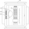
图2为本发明的侧视局部剖视图;Figure 2 is a side partial sectional view of the present invention;
图3为本发明的俯视局部剖视图;Fig. 3 is the top partial sectional view of the present invention;
图4为图1中A处放大图;Fig. 4 is an enlarged view at A in Fig. 1;
图5为本发明的卡位组件主视截面图。FIG. 5 is a front cross-sectional view of the card position assembly of the present invention.
图中:In the picture:
1-扫描组件;2-固定组件;3-调节组件;4-主限位组件;5-副限位组件;6-卡位组件;7-夹持组件;1-Scanning component; 2-Fixing component; 3-Adjusting component; 4-Main limit component; 5-Secondary limit component; 6-Clamping component; 7-Clamping component;
101-固定罩;102-分隔块;103-CCD相机;104-蜂鸣器;105-扫描室;106-滑动室;101-Fixed cover; 102-Separation block; 103-CCD camera; 104-Buzzer; 105-Scanning room; 106-Sliding room;
201-上固定套;202-下固定套;203-拉紧罩;204-滑动罩;205-复位弹簧;206-滑动丝杠;207-手动转齿;208-升降滑动架;209-转齿通过槽;210-橡胶支撑块;201-upper fixing sleeve; 202-lower fixing sleeve; 203-tightening cover; 204-sliding cover; 205-return spring; 206-sliding screw; 207-manual turning gear; 208-lifting sliding frame; Through the groove; 210-rubber support block;
301-调节限位块;302-调节丝杠;303-调节滑套;304-手动转盘;301-adjustment limit block; 302-adjustment screw; 303-adjustment sliding sleeve; 304-manual turntable;
401-承载块;402-夹持转动柱;403-夹持拉紧弹簧;404-夹持限位块;405-夹持弹簧;406-限位滑动块;407-橡胶限位组块;408-线缆夹持槽;409-橡胶夹持块;410-推顶限位弹簧;401-bearing block; 402-holding rotating column; 403-holding tension spring; 404-holding limit block; 405-holding spring; 406-limit sliding block; 407-rubber limit block; 408 -Cable clamping groove; 409-rubber clamping block; 410-top limit spring;
501-夹持固定块;502-滑动柱;503-滑柱拉紧弹簧;504-弹簧承载台;501-Clamping and fixing block; 502-Sliding column; 503-Sliding column tensioning spring; 504-Spring bearing platform;
601-卡位罩;602-滑动块;603-卡位块;604-活动丝杠;605-滑动套;606-连接杆;607-转动连杆;608-转动柱;609-滑动罩;610-按压罩;611-按压弹簧;612-隔离支撑块;601-position cover; 602-slide block; 603-position block; 604-active screw; 605-sliding sleeve; 606-connecting rod; 607-rotating connecting rod; 608-rotating column; 609-sliding cover; 610 -Press cover; 611-Press spring; 612-Isolation support block;
701-固定夹块;702-活动夹块;703-活动拉回弹簧。701-fixed clamp block; 702-movable clamp block; 703-active pull-back spring.
具体实施方式Detailed ways
以下由特定的具体实施例说明本发明的实施方式,熟悉此技术的人士可由本说明书所揭露的内容轻易地了解本发明的其他优点及功效,显然,所描述的实施例是本发明一部分实施例,而不是全部的实施例。基于本发明中的实施例,本领域普通技术人员在没有做出创造性劳动前提下所获得的所有其他实施例,都属于本发明保护的范围。The embodiments of the present invention are described below by specific specific embodiments. Those who are familiar with the technology can easily understand other advantages and effects of the present invention from the contents disclosed in this specification. Obviously, the described embodiments are part of the present invention. , not all examples. Based on the embodiments of the present invention, all other embodiments obtained by those of ordinary skill in the art without creative efforts shall fall within the protection scope of the present invention.
在本发明中是通过设置扫描组件来扫描心电监护仪上的心电波形图,在获得心电波形图之后对其进行分析并根据分析结果发出警示信号,以提醒医护人员,在捕捉扫描信号的同时会限制PICC导管的移动,避免发生不必要的非正常移动现象。避免了医护人员在操作的同时还要分心去关注波形图的变化,并且捕捉相应的波形变化。In the present invention, a scanning component is set to scan the ECG waveform on the ECG monitor, and after the ECG waveform is obtained, it is analyzed and a warning signal is issued according to the analysis result, so as to remind the medical staff. At the same time, it will limit the movement of the PICC catheter to avoid unnecessary abnormal movement. It avoids the distraction of medical staff to pay attention to the changes of the waveform diagram while operating, and captures the corresponding waveform changes.
如图1至图5所示,本发明提供了一种PICC置管辅助装置,包括扫描组件1,该扫描组件1还可外接打印机,使得扫描的心电图信息被打印出方便护士的后续操作,通过自动的识别读图、标记和打印,将极大的提高医护人员的工作效率和准确性,所述扫描组件1的上方设置有固定组件2,所述固定组件2的上方安装有调节组件3,该调节组件3可以精确控制PICC导管插入的深度,其操作简单精度控制高,所述调节组件3的上方设有卡位组件6,该卡位组件6可以卡住调节组件3上的调节丝杠302,使得护士不再插入导管时可以限制住PICC导管的位置,使其不会轻易受到外界的干扰。As shown in FIG. 1 to FIG. 5 , the present invention provides an auxiliary device for PICC placement, including a
所述扫描组件1包括固定罩101,所述固定罩101内通过分隔块102被分为扫描室105和滑动室106,所述扫描室105内安装有CCD相机103,该CCD相机103和蜂鸣器104为市场上常见的设备即可,在所述CCD相机103的上方设有蜂鸣器104,该蜂鸣器104的蜂鸣需要根据CCD相机103来进行操作,当读取到目标波形时可以控制外接打印机自动打印,同时控制卡位组件6卡住调节丝杠302,使得导管不再前行,并发出“已捕捉到双向P波”提示音,当导管尖端到达上腔静脉下1/3并且非常靠近右心房时,P波倒置,此时将导管向外拉,即向后退会出现双向P波,而卡住调节丝杠是为了防止护士紧张导致导管移动量过大,之后,护士可以手动控制卡位组件6复位,然后再缓慢向外拉出导管,当发出“捕捉到P波高是QRS波高60%”的提示音时,控制卡位组件6再次卡住调节丝杠302使导管不再后退,当导管尖端后退时P波会正过来,振幅达到QRS波的50%-80%时为最终目标波形,意味着导管尖端到达上腔静脉下1/3至右心房交界处,控制导管不再后退是为了防止护士移动量过大,导致其需要再次定位的情况发生。当发生上述波形变化时会自动捕捉并且自动虚线化处目标波形,便于后期处理时可以直接对打印出来的波形图进行剪辑。The
在上述中,本发明中所涉及到的CCD相机,通过外接的计算机可以实现对图像的分析,并且准确的获取置管前静息状态、双向P波、P波振幅达QRS波50%-80%的三种状态心电图波形曲线,并自动记录相应的心电图,通过其自动捕捉和打印相应的波形图,整个识别的过程均由智能化来完成,这就降低了对操作医护人员的技术水平要求,可以使得年轻医护人员在单独值班时借助该项技术及时发现和捕捉心电图的改变,由于通过CCD相机采集相应的图像并将其进行转换,以便捕捉相应的数据信号是本领域的常规操作,对此不再进行赘述。In the above, the CCD camera involved in the present invention can analyze the image through an external computer, and accurately obtain the resting state, bidirectional P wave, and P wave amplitude of QRS wave 50%-80% before catheter placement. % of the three state ECG waveform curves, and automatically record the corresponding ECG, through which the corresponding waveform is automatically captured and printed, the entire identification process is completed by intelligence, which reduces the technical level requirements for operating medical staff , which can enable young medical staff to use this technology to detect and capture changes in ECG in time when they are on duty alone. Because it is a routine operation in the field to collect corresponding images through CCD cameras and convert them to capture corresponding data signals. This is not repeated here.
该设备在使用时,其可直接通过固定组件2卡住患者胳膊处,同时再通过调节组件3夹住导管,之后,再通过扫描组件1上的主限位组件4和副限位组件5卡住心电图机,其操作极为简单方便,之后扫描组件1再使用时,一旦有蜂鸣器104发出声音,卡位组件6便会卡住调节组件3上的调节丝杠302,使得护士不会再轻易的移动导管位置,从而提高了容错率和安全性,其较传统的设备防护性更高。When the device is in use, it can directly clamp the patient's arm through the fixing assembly 2, and at the same time clamp the catheter through the adjusting assembly 3, and then clamp the main limit assembly 4 and the
所述卡位组件6包括卡位罩601以及转动连接在卡位罩601内的活动丝杠604,该活动丝杠604位于滑动块602的一侧,同时,其一端连接有驱动电机,该驱动电机的开启与关闭即可受到扫描组件1的控制也可在外界控制,在所述卡位罩601内滑动连接有滑动块602,所述滑动块602的下表面等间距设有若干个对调节组件3限位的卡位块603,且所述滑动块602的上表面对称设置有两个滑动罩609,所述滑动罩609内滑动连接有按压罩610,且所述滑动罩609与按压罩610之间固定安装有按压弹簧611,所述活动丝杠604上滑动连接有滑动套605,所述滑动套605上对称安装有两个连接杆606,该连接杆606可以带动转动连杆607移动,使得转动连杆607间接带着按压罩610滑动,所述连接杆606通过转动连杆607与按压罩610连接,所述转动连杆607的中心位置处安装有转动柱608,该转动柱608位于转动连杆607的中心位置,转动连杆607的一端被按压另一端便会翘起。The clamping assembly 6 includes a clamping
该卡位组件6在使用时,一旦活动丝杠604活动便会使滑动套605滑动,而滑动套605滑动时便会带着连接杆606移动,当连接杆606上移时,转动连杆607的一端便会被带动翘起,之后转动连杆607的另一端便会被带动下压使得按压罩610沿着滑动罩609滑动,此时按压弹簧611会被按压罩610挤压,使得滑动块602沿着卡位罩601下滑,之后,卡位块603便会被带动下滑使得调节丝杠302被压住,然后,即使使用者转动手动转盘304,调节丝杠302也不会轻易转动。When the clamping assembly 6 is in use, once the
所述卡位罩601的下表面对称设置有两个隔离支撑块612,该两个隔离支撑块612可以支撑起卡位罩601,使得调节丝杠302位于两个隔离支撑块612之间,同时卡位块603位于调节丝杠302的正上方,一旦卡位块603下压便会压住调节丝杠302,使其不能随意转动,所述连接杆606为L型结构,而该连接杆606为L型结构,是为了使转动连杆607可以正常被滑动套605带动转动。Two isolation support blocks 612 are symmetrically arranged on the lower surface of the clamping
所述调节组件3包括调节限位块301,该调节限位块301可以使调节滑套303的位置被限制,之后一旦使用者旋转手动转盘304便可使调节丝杠302被带动旋转,之后调节滑套303会沿着调节丝杠302滑动,然后夹持组件7会沿着调节滑套303一起运动,使得导管被带动,之后,一旦蜂鸣器104工作,卡位组件6也会工作,使得调节丝杠302的转动被制止,在所述调节限位块301上转动连接有调节丝杠302,所述调节丝杠302的一端安装有手动转盘304,且所述调节丝杠302的侧壁滑动连接有调节滑套303,所述调节滑套303的侧壁连接有贯穿至固定组件2内的夹持组件7。The adjustment assembly 3 includes an
所述固定罩101的两侧外壁均设置有主限位组件4,且在所述固定罩101的另外两侧外壁均设有副限位组件5,该副限位组件5可以与主限位组件4一起使设备被固定在心电图机上,所述主限位组件4包括承载块401,所述承载块401内转动连接有夹持转动柱402,所述夹持转动柱402与承载块401之间固定安装有夹持拉紧弹簧403,所述夹持转动柱402在远离承载块401的一端通过夹持弹簧405连接有夹持限位块404,所述夹持限位块404的一侧外壁设置有限位滑动块406,该限位滑动块406即可卡住心电图机也可以卡住电源线,该副限位组件5在使用时,使用者可直接拨动夹持限位块404,使其夹住心电图机,同时限位滑动块406也会起到一定的卡位作用使得夹持限位块404不会轻易脱离心电图机,而当夹持限位块404夹住心电图机时,夹持弹簧405会随着心电图机的长度被拉伸,之后,夹持转动柱402会被带动转动,使得夹持拉紧弹簧403被拉伸,此时夹持拉紧弹簧403的弹力增大使得夹持限位块404的夹力增大。The outer walls on both sides of the fixed
所述副限位组件5包括夹持固定块501以及位于滑动室106内的弹簧承载台504,该弹簧承载台504可以同时固定两侧的滑柱拉紧弹簧503,所述夹持固定块501的一侧表面固定安装有若干个滑动柱502,所述滑动柱502位于滑动室106内,且在所述滑动柱502与弹簧承载台504之间固定安装有滑柱拉紧弹簧503,所述夹持固定块501的一侧表面也设置有限位滑动块406。The secondary limiting
该副限位组件5在使用时,使用者可直接拉出夹持固定块501,之后,滑动柱502会被带动沿着滑动室106滑动,从而拉伸滑柱拉紧弹簧503,然后夹持固定块501与固定罩101之间的间距增大,之后,使用者可以通过夹持固定块501固定住心电图机。When the auxiliary limiting
所述限位滑动块406包括橡胶限位组块407,该橡胶限位组块407可以起到一定的限位作用,使得夹持固定块501和夹持限位块404能够更充分的夹住心电图机,而不会轻易滑动,所述橡胶限位组块407上等间距开设有若干个线缆夹持槽408,所述线缆夹持槽408内设有与橡胶限位组块407滑动连接的橡胶夹持块409,所述橡胶夹持块409与橡胶限位组块407之间固定安装有推顶限位弹簧410。The
该限位滑动块406在使用时,一旦有电源线被推入线缆夹持槽408,此时电源线会推动橡胶夹持块409,使其挤压推顶限位弹簧410,之后,待电源线充分进入线缆夹持槽408后,便可被橡胶夹持块409推动从而被固定住。When the
所述固定组件2包括位于固定罩101上方的下固定套202,所述下固定套202的上方设有上固定套201,所述下固定套202的一侧设有拉紧罩203,且所述下固定套202的另一侧设有滑动罩204,在所述上固定套201的内表面对称设置有两个橡胶支撑块210。The fixing assembly 2 includes a
该固定组件2在使用时,其可先通过滑动罩204升起上固定套201然后,再将患者的手臂放置在下固定套202,之后,待手臂放好后,再直接通过滑动罩204降低上固定套201,使得橡胶支撑块210压住患者手臂,该操作简单方便,且可以使用不同肥胖程度的患者。When the fixing assembly 2 is in use, the
所述滑动罩204内转动连接有滑动丝杠206,所述滑动丝杠206的下端设有手动转齿207,所述滑动罩204的下端侧壁与手动转齿207对应位置处开设有转齿通过槽209,所述滑动丝杠206的侧壁滑动连接有升降滑动架208,所述升降滑动架208位于滑动罩204内且与上固定套201直接连接。The sliding
该滑动罩204在操作时,使用者可直接转动手动转齿207,之后,手动转齿207旋转,使得滑动丝杠206被带动转动,之后升降滑动架208会沿着滑动丝杠206上升,使得上固定套201被推动向上直到患者的手臂可以正常放入即可,因所述拉紧罩203内设有与上固定套201直接连接且用于拉回上固定套201的复位弹簧205,故上固定套201上升时,会拉伸复位弹簧205,之后一旦上固定套201复位,便可通过复位弹簧205来进一步保证上固定套201的夹持力。When the sliding
所述夹持组件7包括与调节滑套303直接连接的固定夹块701,所述固定夹块701的一侧转动连接有活动夹块702,所述固定夹块701与活动夹块702之间固定安装有活动拉回弹簧703。The clamping
该夹持组件7在使用时,一旦导管位于活动夹块702与固定夹块701之间,便会推动活动夹块702转动,从而拉伸活动拉回弹簧703,即增大了活动拉回弹簧703的弹力,然后导管的位置便会被充分固定。When the clamping
虽然,上文中已经用一般性说明及具体实施例对本发明作了详尽的描述,但在本发明基础上,可以对之作一些修改或改进,这对本领域技术人员而言是显而易见的。因此,在不偏离本发明精神的基础上所做的这些修改或改进,均属于本发明要求保护的范围。Although the present invention has been described in detail above with general description and specific embodiments, some modifications or improvements can be made on the basis of the present invention, which will be obvious to those skilled in the art. Therefore, these modifications or improvements made without departing from the spirit of the present invention fall within the scope of the claimed protection of the present invention.
Claims (10)
Priority Applications (1)
| Application Number | Priority Date | Filing Date | Title |
|---|---|---|---|
| CN201910388013.3ACN111544739B (en) | 2019-05-10 | 2019-05-10 | A PICC catheterization auxiliary device |
Applications Claiming Priority (1)
| Application Number | Priority Date | Filing Date | Title |
|---|---|---|---|
| CN201910388013.3ACN111544739B (en) | 2019-05-10 | 2019-05-10 | A PICC catheterization auxiliary device |
Publications (2)
| Publication Number | Publication Date |
|---|---|
| CN111544739Atrue CN111544739A (en) | 2020-08-18 |
| CN111544739B CN111544739B (en) | 2024-11-12 |
Family
ID=71996562
Family Applications (1)
| Application Number | Title | Priority Date | Filing Date |
|---|---|---|---|
| CN201910388013.3AActiveCN111544739B (en) | 2019-05-10 | 2019-05-10 | A PICC catheterization auxiliary device |
Country Status (1)
| Country | Link |
|---|---|
| CN (1) | CN111544739B (en) |
Cited By (2)
| Publication number | Priority date | Publication date | Assignee | Title |
|---|---|---|---|---|
| CN118079196A (en)* | 2024-04-29 | 2024-05-28 | 广州市第一人民医院(广州消化疾病中心、广州医科大学附属市一人民医院、华南理工大学附属第二医院) | A PICC catheterization auxiliary device |
| CN118750739A (en)* | 2024-07-03 | 2024-10-11 | 中国人民解放军空军军医大学 | An intelligent positioning device based on PICC care |
Citations (14)
| Publication number | Priority date | Publication date | Assignee | Title |
|---|---|---|---|---|
| CN201088584Y (en)* | 2007-08-27 | 2008-07-23 | 重庆邮电大学 | Cardiogram read device |
| US20110071394A1 (en)* | 2009-09-23 | 2011-03-24 | Fedinec James J | Central venous catheter kit with line gripping and needle localizing devices |
| CN102939129A (en)* | 2010-05-14 | 2013-02-20 | C·R·巴德股份有限公司 | Catheter placement devices and methods |
| CN105233392A (en)* | 2014-07-09 | 2016-01-13 | 山东百多安医疗器械有限公司 | Central venous catheter having function of indicating position thereof according to electrocardiograph signal |
| US20160096003A1 (en)* | 2014-08-22 | 2016-04-07 | Jaywant P. Parmar | Advanced Electromagnetic Motion and Tracking Peripherally Inserted Central Venous Catheter System with Extended Endovascular Applications |
| CN205338948U (en)* | 2016-01-08 | 2016-06-29 | 无锡市人民医院 | A portable electrocardio guidance system of compact type for PICC head end location |
| US20160184552A1 (en)* | 2013-02-25 | 2016-06-30 | Institute Of Automation, Chinese Academy Of Sciences | Catheter or guide wire manipulating device with two-point-clamping for vascular intervention |
| CN205460364U (en)* | 2016-02-25 | 2016-08-17 | 孔燕 | Ductus venosus puts effective fixed auxiliary stand |
| CN205814848U (en)* | 2016-05-10 | 2016-12-21 | 徐州市中心医院 | The alignment system of Theodolite measuring systems |
| US20160375223A1 (en)* | 2015-06-23 | 2016-12-29 | Traumatek Solutions, B.V. | Vessel cannulation device and method of use |
| US20170273713A1 (en)* | 2016-01-21 | 2017-09-28 | Amit Shah | Intravenous access assist device |
| CN107297016A (en)* | 2017-08-01 | 2017-10-27 | 张建英 | PICC Vein Tube intelligent control operation instruments for leukaemic's chemotherapy |
| CN208641501U (en)* | 2018-03-29 | 2019-03-26 | 西安交通大学医学院第一附属医院 | PICC cannula protection device |
| CN211273037U (en)* | 2019-05-10 | 2020-08-18 | 华中科技大学同济医学院附属协和医院 | PICC puts a tub auxiliary device |
- 2019
- 2019-05-10CNCN201910388013.3Apatent/CN111544739B/enactiveActive
Patent Citations (14)
| Publication number | Priority date | Publication date | Assignee | Title |
|---|---|---|---|---|
| CN201088584Y (en)* | 2007-08-27 | 2008-07-23 | 重庆邮电大学 | Cardiogram read device |
| US20110071394A1 (en)* | 2009-09-23 | 2011-03-24 | Fedinec James J | Central venous catheter kit with line gripping and needle localizing devices |
| CN102939129A (en)* | 2010-05-14 | 2013-02-20 | C·R·巴德股份有限公司 | Catheter placement devices and methods |
| US20160184552A1 (en)* | 2013-02-25 | 2016-06-30 | Institute Of Automation, Chinese Academy Of Sciences | Catheter or guide wire manipulating device with two-point-clamping for vascular intervention |
| CN105233392A (en)* | 2014-07-09 | 2016-01-13 | 山东百多安医疗器械有限公司 | Central venous catheter having function of indicating position thereof according to electrocardiograph signal |
| US20160096003A1 (en)* | 2014-08-22 | 2016-04-07 | Jaywant P. Parmar | Advanced Electromagnetic Motion and Tracking Peripherally Inserted Central Venous Catheter System with Extended Endovascular Applications |
| US20160375223A1 (en)* | 2015-06-23 | 2016-12-29 | Traumatek Solutions, B.V. | Vessel cannulation device and method of use |
| CN205338948U (en)* | 2016-01-08 | 2016-06-29 | 无锡市人民医院 | A portable electrocardio guidance system of compact type for PICC head end location |
| US20170273713A1 (en)* | 2016-01-21 | 2017-09-28 | Amit Shah | Intravenous access assist device |
| CN205460364U (en)* | 2016-02-25 | 2016-08-17 | 孔燕 | Ductus venosus puts effective fixed auxiliary stand |
| CN205814848U (en)* | 2016-05-10 | 2016-12-21 | 徐州市中心医院 | The alignment system of Theodolite measuring systems |
| CN107297016A (en)* | 2017-08-01 | 2017-10-27 | 张建英 | PICC Vein Tube intelligent control operation instruments for leukaemic's chemotherapy |
| CN208641501U (en)* | 2018-03-29 | 2019-03-26 | 西安交通大学医学院第一附属医院 | PICC cannula protection device |
| CN211273037U (en)* | 2019-05-10 | 2020-08-18 | 华中科技大学同济医学院附属协和医院 | PICC puts a tub auxiliary device |
Cited By (3)
| Publication number | Priority date | Publication date | Assignee | Title |
|---|---|---|---|---|
| CN118079196A (en)* | 2024-04-29 | 2024-05-28 | 广州市第一人民医院(广州消化疾病中心、广州医科大学附属市一人民医院、华南理工大学附属第二医院) | A PICC catheterization auxiliary device |
| CN118079196B (en)* | 2024-04-29 | 2024-07-02 | 广州市第一人民医院(广州消化疾病中心、广州医科大学附属市一人民医院、华南理工大学附属第二医院) | PICC puts tub auxiliary device |
| CN118750739A (en)* | 2024-07-03 | 2024-10-11 | 中国人民解放军空军军医大学 | An intelligent positioning device based on PICC care |
Also Published As
| Publication number | Publication date |
|---|---|
| CN111544739B (en) | 2024-11-12 |
Similar Documents
| Publication | Publication Date | Title |
|---|---|---|
| CN111544739A (en) | A kind of auxiliary device for PICC tube placement | |
| CN211273037U (en) | PICC puts a tub auxiliary device | |
| CN219021528U (en) | Catheter driving device of vascular intervention surgical robot | |
| CN115006647A (en) | A kind of skin test device with adjustable angle for nursing department | |
| CN220423947U (en) | Endoscopic fluorescence imaging auxiliary puncture equipment | |
| CN221243269U (en) | Health management record card | |
| CN222566567U (en) | Cardiac intervention catheter nursing fixer | |
| CN221830624U (en) | Pet electronic computer fault scanning device | |
| CN215445957U (en) | Image photographing bracket for oral clinical medicine | |
| CN215738926U (en) | Clinical fetus-voice meter for obstetrics and gynecology department | |
| CN216933890U (en) | Leg frame fixing device for assisting gynecological operation | |
| CN215017113U (en) | Novel adjustable digestive endoscope bracket | |
| CN221149054U (en) | Image piece fixing device | |
| CN223133798U (en) | Digestion object analysis device for gastroenterology | |
| CN216169238U (en) | A positioning device for abdominal insulin injection with skin pinch function | |
| CN216908384U (en) | Falling-proof test fixing frame for clinical laboratory | |
| CN218451672U (en) | Fixed photographing device for laboratory mouse | |
| CN214907124U (en) | CT diagnosis auxiliary device | |
| CN217793117U (en) | Radiation protection device for ultrasound department examination | |
| CN221712554U (en) | Stretcher support convenient to fix for medical examination | |
| CN219127914U (en) | Catheter fixing device for gastrointestinal surgery | |
| CN221555674U (en) | Positioning and developing track device suitable for ultrasonic probe | |
| CN110693447A (en) | Opening limiter for oral cavity radiation image acquisition | |
| CN220236862U (en) | Inspection device | |
| CN210093337U (en) | ECG reading stand |
Legal Events
| Date | Code | Title | Description |
|---|---|---|---|
| PB01 | Publication | ||
| PB01 | Publication | ||
| SE01 | Entry into force of request for substantive examination | ||
| SE01 | Entry into force of request for substantive examination | ||
| GR01 | Patent grant | ||
| GR01 | Patent grant | ||
| CB03 | Change of inventor or designer information | Inventor after:Xin Ping Inventor after:Pang Xing Inventor after:Yin Nijuan Inventor after:Bao Aiqin Inventor after:Luo Yang Inventor after:Liu Weihong Inventor after:Chen Sha Inventor after:Xu Wenjie Inventor after:Wu Huameng Inventor after:Kong Hefang Inventor after:Yu Qian Inventor before:Bao Aiqin Inventor before:Pang Xing Inventor before:Yin Nijuan Inventor before:Xin Ping Inventor before:Luo Yang Inventor before:Liu Weihong Inventor before:Chen Sha Inventor before:Xu Wenjie Inventor before:Wu Huameng Inventor before:Kong Hefang Inventor before:Yu Qian | |
| CB03 | Change of inventor or designer information |