CN111542274A - Surgical instrument including biased switching mechanism - Google Patents
Surgical instrument including biased switching mechanismDownload PDFInfo
- Publication number
- CN111542274A CN111542274ACN201880084884.XACN201880084884ACN111542274ACN 111542274 ACN111542274 ACN 111542274ACN 201880084884 ACN201880084884 ACN 201880084884ACN 111542274 ACN111542274 ACN 111542274A
- Authority
- CN
- China
- Prior art keywords
- drive
- clutch
- shaft
- end effector
- assembly
- Prior art date
- Legal status (The legal status is an assumption and is not a legal conclusion. Google has not performed a legal analysis and makes no representation as to the accuracy of the status listed.)
- Granted
Links
Images


Classifications
- A—HUMAN NECESSITIES
- A61—MEDICAL OR VETERINARY SCIENCE; HYGIENE
- A61B—DIAGNOSIS; SURGERY; IDENTIFICATION
- A61B17/00—Surgical instruments, devices or methods
- A61B17/12—Surgical instruments, devices or methods for ligaturing or otherwise compressing tubular parts of the body, e.g. blood vessels or umbilical cord
- A61B17/128—Surgical instruments, devices or methods for ligaturing or otherwise compressing tubular parts of the body, e.g. blood vessels or umbilical cord for applying or removing clamps or clips
- A61B17/1285—Surgical instruments, devices or methods for ligaturing or otherwise compressing tubular parts of the body, e.g. blood vessels or umbilical cord for applying or removing clamps or clips for minimally invasive surgery
- A—HUMAN NECESSITIES
- A61—MEDICAL OR VETERINARY SCIENCE; HYGIENE
- A61B—DIAGNOSIS; SURGERY; IDENTIFICATION
- A61B17/00—Surgical instruments, devices or methods
- A61B17/04—Surgical instruments, devices or methods for suturing wounds; Holders or packages for needles or suture materials
- A61B17/0469—Suturing instruments for use in minimally invasive surgery, e.g. endoscopic surgery
- A—HUMAN NECESSITIES
- A61—MEDICAL OR VETERINARY SCIENCE; HYGIENE
- A61B—DIAGNOSIS; SURGERY; IDENTIFICATION
- A61B17/00—Surgical instruments, devices or methods
- A61B17/04—Surgical instruments, devices or methods for suturing wounds; Holders or packages for needles or suture materials
- A61B17/0482—Needle or suture guides
- A—HUMAN NECESSITIES
- A61—MEDICAL OR VETERINARY SCIENCE; HYGIENE
- A61B—DIAGNOSIS; SURGERY; IDENTIFICATION
- A61B17/00—Surgical instruments, devices or methods
- A61B17/04—Surgical instruments, devices or methods for suturing wounds; Holders or packages for needles or suture materials
- A61B17/06—Needles ; Sutures; Needle-suture combinations; Holders or packages for needles or suture materials
- A61B17/06114—Packages or dispensers for needles or sutures
- A—HUMAN NECESSITIES
- A61—MEDICAL OR VETERINARY SCIENCE; HYGIENE
- A61B—DIAGNOSIS; SURGERY; IDENTIFICATION
- A61B17/00—Surgical instruments, devices or methods
- A61B17/04—Surgical instruments, devices or methods for suturing wounds; Holders or packages for needles or suture materials
- A61B17/06—Needles ; Sutures; Needle-suture combinations; Holders or packages for needles or suture materials
- A61B17/062—Needle manipulators
- A—HUMAN NECESSITIES
- A61—MEDICAL OR VETERINARY SCIENCE; HYGIENE
- A61B—DIAGNOSIS; SURGERY; IDENTIFICATION
- A61B17/00—Surgical instruments, devices or methods
- A61B17/12—Surgical instruments, devices or methods for ligaturing or otherwise compressing tubular parts of the body, e.g. blood vessels or umbilical cord
- A61B17/122—Clamps or clips, e.g. for the umbilical cord
- A61B17/1222—Packages or dispensers therefor
- A—HUMAN NECESSITIES
- A61—MEDICAL OR VETERINARY SCIENCE; HYGIENE
- A61B—DIAGNOSIS; SURGERY; IDENTIFICATION
- A61B17/00—Surgical instruments, devices or methods
- A61B17/12—Surgical instruments, devices or methods for ligaturing or otherwise compressing tubular parts of the body, e.g. blood vessels or umbilical cord
- A61B17/122—Clamps or clips, e.g. for the umbilical cord
- A61B17/1227—Spring clips
- A—HUMAN NECESSITIES
- A61—MEDICAL OR VETERINARY SCIENCE; HYGIENE
- A61B—DIAGNOSIS; SURGERY; IDENTIFICATION
- A61B17/00—Surgical instruments, devices or methods
- A61B17/28—Surgical forceps
- A61B17/285—Surgical forceps combined with cutting implements
- A—HUMAN NECESSITIES
- A61—MEDICAL OR VETERINARY SCIENCE; HYGIENE
- A61B—DIAGNOSIS; SURGERY; IDENTIFICATION
- A61B17/00—Surgical instruments, devices or methods
- A61B17/28—Surgical forceps
- A61B17/29—Forceps for use in minimally invasive surgery
- A—HUMAN NECESSITIES
- A61—MEDICAL OR VETERINARY SCIENCE; HYGIENE
- A61B—DIAGNOSIS; SURGERY; IDENTIFICATION
- A61B17/00—Surgical instruments, devices or methods
- A61B17/28—Surgical forceps
- A61B17/29—Forceps for use in minimally invasive surgery
- A61B17/2909—Handles
- A—HUMAN NECESSITIES
- A61—MEDICAL OR VETERINARY SCIENCE; HYGIENE
- A61B—DIAGNOSIS; SURGERY; IDENTIFICATION
- A61B17/00—Surgical instruments, devices or methods
- A61B17/28—Surgical forceps
- A61B17/29—Forceps for use in minimally invasive surgery
- A61B17/295—Forceps for use in minimally invasive surgery combined with cutting implements
- A—HUMAN NECESSITIES
- A61—MEDICAL OR VETERINARY SCIENCE; HYGIENE
- A61B—DIAGNOSIS; SURGERY; IDENTIFICATION
- A61B17/00—Surgical instruments, devices or methods
- A61B17/32—Surgical cutting instruments
- A61B17/320068—Surgical cutting instruments using mechanical vibrations, e.g. ultrasonic
- A—HUMAN NECESSITIES
- A61—MEDICAL OR VETERINARY SCIENCE; HYGIENE
- A61B—DIAGNOSIS; SURGERY; IDENTIFICATION
- A61B17/00—Surgical instruments, devices or methods
- A61B17/34—Trocars; Puncturing needles
- A61B17/3417—Details of tips or shafts, e.g. grooves, expandable, bendable; Multiple coaxial sliding cannulas, e.g. for dilating
- A61B17/3421—Cannulas
- A—HUMAN NECESSITIES
- A61—MEDICAL OR VETERINARY SCIENCE; HYGIENE
- A61B—DIAGNOSIS; SURGERY; IDENTIFICATION
- A61B18/00—Surgical instruments, devices or methods for transferring non-mechanical forms of energy to or from the body
- A61B18/04—Surgical instruments, devices or methods for transferring non-mechanical forms of energy to or from the body by heating
- A61B18/12—Surgical instruments, devices or methods for transferring non-mechanical forms of energy to or from the body by heating by passing a current through the tissue to be heated, e.g. high-frequency current
- A61B18/14—Probes or electrodes therefor
- A61B18/1442—Probes having pivoting end effectors, e.g. forceps
- A61B18/1445—Probes having pivoting end effectors, e.g. forceps at the distal end of a shaft, e.g. forceps or scissors at the end of a rigid rod
- A—HUMAN NECESSITIES
- A61—MEDICAL OR VETERINARY SCIENCE; HYGIENE
- A61B—DIAGNOSIS; SURGERY; IDENTIFICATION
- A61B34/00—Computer-aided surgery; Manipulators or robots specially adapted for use in surgery
- A61B34/30—Surgical robots
- A—HUMAN NECESSITIES
- A61—MEDICAL OR VETERINARY SCIENCE; HYGIENE
- A61B—DIAGNOSIS; SURGERY; IDENTIFICATION
- A61B34/00—Computer-aided surgery; Manipulators or robots specially adapted for use in surgery
- A61B34/70—Manipulators specially adapted for use in surgery
- A61B34/76—Manipulators having means for providing feel, e.g. force or tactile feedback
- A—HUMAN NECESSITIES
- A61—MEDICAL OR VETERINARY SCIENCE; HYGIENE
- A61B—DIAGNOSIS; SURGERY; IDENTIFICATION
- A61B90/00—Instruments, implements or accessories specially adapted for surgery or diagnosis and not covered by any of the groups A61B1/00 - A61B50/00, e.g. for luxation treatment or for protecting wound edges
- A61B90/03—Automatic limiting or abutting means, e.g. for safety
- A—HUMAN NECESSITIES
- A61—MEDICAL OR VETERINARY SCIENCE; HYGIENE
- A61B—DIAGNOSIS; SURGERY; IDENTIFICATION
- A61B90/00—Instruments, implements or accessories specially adapted for surgery or diagnosis and not covered by any of the groups A61B1/00 - A61B50/00, e.g. for luxation treatment or for protecting wound edges
- A61B90/90—Identification means for patients or instruments, e.g. tags
- A61B90/98—Identification means for patients or instruments, e.g. tags using electromagnetic means, e.g. transponders
- G—PHYSICS
- G16—INFORMATION AND COMMUNICATION TECHNOLOGY [ICT] SPECIALLY ADAPTED FOR SPECIFIC APPLICATION FIELDS
- G16H—HEALTHCARE INFORMATICS, i.e. INFORMATION AND COMMUNICATION TECHNOLOGY [ICT] SPECIALLY ADAPTED FOR THE HANDLING OR PROCESSING OF MEDICAL OR HEALTHCARE DATA
- G16H40/00—ICT specially adapted for the management or administration of healthcare resources or facilities; ICT specially adapted for the management or operation of medical equipment or devices
- G16H40/20—ICT specially adapted for the management or administration of healthcare resources or facilities; ICT specially adapted for the management or operation of medical equipment or devices for the management or administration of healthcare resources or facilities, e.g. managing hospital staff or surgery rooms
- G—PHYSICS
- G16—INFORMATION AND COMMUNICATION TECHNOLOGY [ICT] SPECIALLY ADAPTED FOR SPECIFIC APPLICATION FIELDS
- G16H—HEALTHCARE INFORMATICS, i.e. INFORMATION AND COMMUNICATION TECHNOLOGY [ICT] SPECIALLY ADAPTED FOR THE HANDLING OR PROCESSING OF MEDICAL OR HEALTHCARE DATA
- G16H40/00—ICT specially adapted for the management or administration of healthcare resources or facilities; ICT specially adapted for the management or operation of medical equipment or devices
- G16H40/60—ICT specially adapted for the management or administration of healthcare resources or facilities; ICT specially adapted for the management or operation of medical equipment or devices for the operation of medical equipment or devices
- G16H40/63—ICT specially adapted for the management or administration of healthcare resources or facilities; ICT specially adapted for the management or operation of medical equipment or devices for the operation of medical equipment or devices for local operation
- G—PHYSICS
- G16—INFORMATION AND COMMUNICATION TECHNOLOGY [ICT] SPECIALLY ADAPTED FOR SPECIFIC APPLICATION FIELDS
- G16H—HEALTHCARE INFORMATICS, i.e. INFORMATION AND COMMUNICATION TECHNOLOGY [ICT] SPECIALLY ADAPTED FOR THE HANDLING OR PROCESSING OF MEDICAL OR HEALTHCARE DATA
- G16H40/00—ICT specially adapted for the management or administration of healthcare resources or facilities; ICT specially adapted for the management or operation of medical equipment or devices
- G16H40/60—ICT specially adapted for the management or administration of healthcare resources or facilities; ICT specially adapted for the management or operation of medical equipment or devices for the operation of medical equipment or devices
- G16H40/67—ICT specially adapted for the management or administration of healthcare resources or facilities; ICT specially adapted for the management or operation of medical equipment or devices for the operation of medical equipment or devices for remote operation
- G—PHYSICS
- G16—INFORMATION AND COMMUNICATION TECHNOLOGY [ICT] SPECIALLY ADAPTED FOR SPECIFIC APPLICATION FIELDS
- G16H—HEALTHCARE INFORMATICS, i.e. INFORMATION AND COMMUNICATION TECHNOLOGY [ICT] SPECIALLY ADAPTED FOR THE HANDLING OR PROCESSING OF MEDICAL OR HEALTHCARE DATA
- G16H50/00—ICT specially adapted for medical diagnosis, medical simulation or medical data mining; ICT specially adapted for detecting, monitoring or modelling epidemics or pandemics
- G16H50/70—ICT specially adapted for medical diagnosis, medical simulation or medical data mining; ICT specially adapted for detecting, monitoring or modelling epidemics or pandemics for mining of medical data, e.g. analysing previous cases of other patients
- A—HUMAN NECESSITIES
- A61—MEDICAL OR VETERINARY SCIENCE; HYGIENE
- A61B—DIAGNOSIS; SURGERY; IDENTIFICATION
- A61B17/00—Surgical instruments, devices or methods
- A61B17/04—Surgical instruments, devices or methods for suturing wounds; Holders or packages for needles or suture materials
- A61B17/06—Needles ; Sutures; Needle-suture combinations; Holders or packages for needles or suture materials
- A—HUMAN NECESSITIES
- A61—MEDICAL OR VETERINARY SCIENCE; HYGIENE
- A61B—DIAGNOSIS; SURGERY; IDENTIFICATION
- A61B17/00—Surgical instruments, devices or methods
- A61B17/068—Surgical staplers, e.g. containing multiple staples or clamps
- A—HUMAN NECESSITIES
- A61—MEDICAL OR VETERINARY SCIENCE; HYGIENE
- A61B—DIAGNOSIS; SURGERY; IDENTIFICATION
- A61B17/00—Surgical instruments, devices or methods
- A61B17/32—Surgical cutting instruments
- A61B17/3201—Scissors
- A—HUMAN NECESSITIES
- A61—MEDICAL OR VETERINARY SCIENCE; HYGIENE
- A61B—DIAGNOSIS; SURGERY; IDENTIFICATION
- A61B17/00—Surgical instruments, devices or methods
- A61B17/34—Trocars; Puncturing needles
- A61B17/3417—Details of tips or shafts, e.g. grooves, expandable, bendable; Multiple coaxial sliding cannulas, e.g. for dilating
- A—HUMAN NECESSITIES
- A61—MEDICAL OR VETERINARY SCIENCE; HYGIENE
- A61B—DIAGNOSIS; SURGERY; IDENTIFICATION
- A61B17/00—Surgical instruments, devices or methods
- A61B2017/00017—Electrical control of surgical instruments
- A—HUMAN NECESSITIES
- A61—MEDICAL OR VETERINARY SCIENCE; HYGIENE
- A61B—DIAGNOSIS; SURGERY; IDENTIFICATION
- A61B17/00—Surgical instruments, devices or methods
- A61B2017/00017—Electrical control of surgical instruments
- A61B2017/00022—Sensing or detecting at the treatment site
- A61B2017/00039—Electric or electromagnetic phenomena other than conductivity, e.g. capacity, inductivity, Hall effect
- A—HUMAN NECESSITIES
- A61—MEDICAL OR VETERINARY SCIENCE; HYGIENE
- A61B—DIAGNOSIS; SURGERY; IDENTIFICATION
- A61B17/00—Surgical instruments, devices or methods
- A61B2017/00017—Electrical control of surgical instruments
- A61B2017/00115—Electrical control of surgical instruments with audible or visual output
- A61B2017/00119—Electrical control of surgical instruments with audible or visual output alarm; indicating an abnormal situation
- A61B2017/00123—Electrical control of surgical instruments with audible or visual output alarm; indicating an abnormal situation and automatic shutdown
- A—HUMAN NECESSITIES
- A61—MEDICAL OR VETERINARY SCIENCE; HYGIENE
- A61B—DIAGNOSIS; SURGERY; IDENTIFICATION
- A61B17/00—Surgical instruments, devices or methods
- A61B2017/00017—Electrical control of surgical instruments
- A61B2017/00115—Electrical control of surgical instruments with audible or visual output
- A61B2017/00128—Electrical control of surgical instruments with audible or visual output related to intensity or progress of surgical action
- A—HUMAN NECESSITIES
- A61—MEDICAL OR VETERINARY SCIENCE; HYGIENE
- A61B—DIAGNOSIS; SURGERY; IDENTIFICATION
- A61B17/00—Surgical instruments, devices or methods
- A61B2017/00017—Electrical control of surgical instruments
- A61B2017/00137—Details of operation mode
- A61B2017/00154—Details of operation mode pulsed
- A61B2017/00172—Pulse trains, bursts, intermittent continuous operation
- A—HUMAN NECESSITIES
- A61—MEDICAL OR VETERINARY SCIENCE; HYGIENE
- A61B—DIAGNOSIS; SURGERY; IDENTIFICATION
- A61B17/00—Surgical instruments, devices or methods
- A61B2017/00017—Electrical control of surgical instruments
- A61B2017/00221—Electrical control of surgical instruments with wireless transmission of data, e.g. by infrared radiation or radiowaves
- A—HUMAN NECESSITIES
- A61—MEDICAL OR VETERINARY SCIENCE; HYGIENE
- A61B—DIAGNOSIS; SURGERY; IDENTIFICATION
- A61B17/00—Surgical instruments, devices or methods
- A61B2017/0023—Surgical instruments, devices or methods disposable
- A—HUMAN NECESSITIES
- A61—MEDICAL OR VETERINARY SCIENCE; HYGIENE
- A61B—DIAGNOSIS; SURGERY; IDENTIFICATION
- A61B17/00—Surgical instruments, devices or methods
- A61B17/00234—Surgical instruments, devices or methods for minimally invasive surgery
- A61B2017/00292—Surgical instruments, devices or methods for minimally invasive surgery mounted on or guided by flexible, e.g. catheter-like, means
- A61B2017/003—Steerable
- A61B2017/00305—Constructional details of the flexible means
- A61B2017/00309—Cut-outs or slits
- A—HUMAN NECESSITIES
- A61—MEDICAL OR VETERINARY SCIENCE; HYGIENE
- A61B—DIAGNOSIS; SURGERY; IDENTIFICATION
- A61B17/00—Surgical instruments, devices or methods
- A61B17/00234—Surgical instruments, devices or methods for minimally invasive surgery
- A61B2017/00292—Surgical instruments, devices or methods for minimally invasive surgery mounted on or guided by flexible, e.g. catheter-like, means
- A61B2017/003—Steerable
- A61B2017/00318—Steering mechanisms
- A61B2017/00323—Cables or rods
- A61B2017/00327—Cables or rods with actuating members moving in opposite directions
- A—HUMAN NECESSITIES
- A61—MEDICAL OR VETERINARY SCIENCE; HYGIENE
- A61B—DIAGNOSIS; SURGERY; IDENTIFICATION
- A61B17/00—Surgical instruments, devices or methods
- A61B17/00234—Surgical instruments, devices or methods for minimally invasive surgery
- A61B2017/00353—Surgical instruments, devices or methods for minimally invasive surgery one mechanical instrument performing multiple functions, e.g. cutting and grasping
- A—HUMAN NECESSITIES
- A61—MEDICAL OR VETERINARY SCIENCE; HYGIENE
- A61B—DIAGNOSIS; SURGERY; IDENTIFICATION
- A61B17/00—Surgical instruments, devices or methods
- A61B2017/00367—Details of actuation of instruments, e.g. relations between pushing buttons, or the like, and activation of the tool, working tip, or the like
- A61B2017/00389—Button or wheel for performing multiple functions, e.g. rotation of shaft and end effector
- A61B2017/00393—Button or wheel for performing multiple functions, e.g. rotation of shaft and end effector with means for switching between functions
- A—HUMAN NECESSITIES
- A61—MEDICAL OR VETERINARY SCIENCE; HYGIENE
- A61B—DIAGNOSIS; SURGERY; IDENTIFICATION
- A61B17/00—Surgical instruments, devices or methods
- A61B2017/00367—Details of actuation of instruments, e.g. relations between pushing buttons, or the like, and activation of the tool, working tip, or the like
- A61B2017/00398—Details of actuation of instruments, e.g. relations between pushing buttons, or the like, and activation of the tool, working tip, or the like using powered actuators, e.g. stepper motors, solenoids
- A—HUMAN NECESSITIES
- A61—MEDICAL OR VETERINARY SCIENCE; HYGIENE
- A61B—DIAGNOSIS; SURGERY; IDENTIFICATION
- A61B17/00—Surgical instruments, devices or methods
- A61B2017/00367—Details of actuation of instruments, e.g. relations between pushing buttons, or the like, and activation of the tool, working tip, or the like
- A61B2017/00407—Ratchet means
- A—HUMAN NECESSITIES
- A61—MEDICAL OR VETERINARY SCIENCE; HYGIENE
- A61B—DIAGNOSIS; SURGERY; IDENTIFICATION
- A61B17/00—Surgical instruments, devices or methods
- A61B2017/0042—Surgical instruments, devices or methods with special provisions for gripping
- A61B2017/00424—Surgical instruments, devices or methods with special provisions for gripping ergonomic, e.g. fitting in fist
- A—HUMAN NECESSITIES
- A61—MEDICAL OR VETERINARY SCIENCE; HYGIENE
- A61B—DIAGNOSIS; SURGERY; IDENTIFICATION
- A61B17/00—Surgical instruments, devices or methods
- A61B2017/0046—Surgical instruments, devices or methods with a releasable handle; with handle and operating part separable
- A—HUMAN NECESSITIES
- A61—MEDICAL OR VETERINARY SCIENCE; HYGIENE
- A61B—DIAGNOSIS; SURGERY; IDENTIFICATION
- A61B17/00—Surgical instruments, devices or methods
- A61B2017/0046—Surgical instruments, devices or methods with a releasable handle; with handle and operating part separable
- A61B2017/00464—Surgical instruments, devices or methods with a releasable handle; with handle and operating part separable for use with different instruments
- A—HUMAN NECESSITIES
- A61—MEDICAL OR VETERINARY SCIENCE; HYGIENE
- A61B—DIAGNOSIS; SURGERY; IDENTIFICATION
- A61B17/00—Surgical instruments, devices or methods
- A61B2017/0046—Surgical instruments, devices or methods with a releasable handle; with handle and operating part separable
- A61B2017/00473—Distal part, e.g. tip or head
- A—HUMAN NECESSITIES
- A61—MEDICAL OR VETERINARY SCIENCE; HYGIENE
- A61B—DIAGNOSIS; SURGERY; IDENTIFICATION
- A61B17/00—Surgical instruments, devices or methods
- A61B2017/00477—Coupling
- A—HUMAN NECESSITIES
- A61—MEDICAL OR VETERINARY SCIENCE; HYGIENE
- A61B—DIAGNOSIS; SURGERY; IDENTIFICATION
- A61B17/00—Surgical instruments, devices or methods
- A61B2017/00477—Coupling
- A61B2017/00482—Coupling with a code
- A—HUMAN NECESSITIES
- A61—MEDICAL OR VETERINARY SCIENCE; HYGIENE
- A61B—DIAGNOSIS; SURGERY; IDENTIFICATION
- A61B17/00—Surgical instruments, devices or methods
- A61B2017/00526—Methods of manufacturing
- A—HUMAN NECESSITIES
- A61—MEDICAL OR VETERINARY SCIENCE; HYGIENE
- A61B—DIAGNOSIS; SURGERY; IDENTIFICATION
- A61B17/00—Surgical instruments, devices or methods
- A61B2017/00681—Aspects not otherwise provided for
- A61B2017/00734—Aspects not otherwise provided for battery operated
- A—HUMAN NECESSITIES
- A61—MEDICAL OR VETERINARY SCIENCE; HYGIENE
- A61B—DIAGNOSIS; SURGERY; IDENTIFICATION
- A61B17/00—Surgical instruments, devices or methods
- A61B2017/00831—Material properties
- A61B2017/00876—Material properties magnetic
- A—HUMAN NECESSITIES
- A61—MEDICAL OR VETERINARY SCIENCE; HYGIENE
- A61B—DIAGNOSIS; SURGERY; IDENTIFICATION
- A61B17/00—Surgical instruments, devices or methods
- A61B17/04—Surgical instruments, devices or methods for suturing wounds; Holders or packages for needles or suture materials
- A61B17/06—Needles ; Sutures; Needle-suture combinations; Holders or packages for needles or suture materials
- A61B17/06066—Needles, e.g. needle tip configurations
- A61B2017/06076—Needles, e.g. needle tip configurations helically or spirally coiled
- A—HUMAN NECESSITIES
- A61—MEDICAL OR VETERINARY SCIENCE; HYGIENE
- A61B—DIAGNOSIS; SURGERY; IDENTIFICATION
- A61B17/00—Surgical instruments, devices or methods
- A61B17/04—Surgical instruments, devices or methods for suturing wounds; Holders or packages for needles or suture materials
- A61B17/06—Needles ; Sutures; Needle-suture combinations; Holders or packages for needles or suture materials
- A61B17/06066—Needles, e.g. needle tip configurations
- A61B2017/0608—J-shaped
- A—HUMAN NECESSITIES
- A61—MEDICAL OR VETERINARY SCIENCE; HYGIENE
- A61B—DIAGNOSIS; SURGERY; IDENTIFICATION
- A61B17/00—Surgical instruments, devices or methods
- A61B17/28—Surgical forceps
- A61B17/2812—Surgical forceps with a single pivotal connection
- A61B17/282—Jaws
- A61B2017/2825—Inserts of different material in jaws
- A—HUMAN NECESSITIES
- A61—MEDICAL OR VETERINARY SCIENCE; HYGIENE
- A61B—DIAGNOSIS; SURGERY; IDENTIFICATION
- A61B17/00—Surgical instruments, devices or methods
- A61B17/28—Surgical forceps
- A61B17/29—Forceps for use in minimally invasive surgery
- A61B2017/2901—Details of shaft
- A61B2017/2902—Details of shaft characterized by features of the actuating rod
- A61B2017/2903—Details of shaft characterized by features of the actuating rod transferring rotary motion
- A—HUMAN NECESSITIES
- A61—MEDICAL OR VETERINARY SCIENCE; HYGIENE
- A61B—DIAGNOSIS; SURGERY; IDENTIFICATION
- A61B17/00—Surgical instruments, devices or methods
- A61B17/28—Surgical forceps
- A61B17/29—Forceps for use in minimally invasive surgery
- A61B17/2909—Handles
- A61B2017/291—Handles the position of the handle being adjustable with respect to the shaft
- A—HUMAN NECESSITIES
- A61—MEDICAL OR VETERINARY SCIENCE; HYGIENE
- A61B—DIAGNOSIS; SURGERY; IDENTIFICATION
- A61B17/00—Surgical instruments, devices or methods
- A61B17/28—Surgical forceps
- A61B17/29—Forceps for use in minimally invasive surgery
- A61B2017/2926—Details of heads or jaws
- A—HUMAN NECESSITIES
- A61—MEDICAL OR VETERINARY SCIENCE; HYGIENE
- A61B—DIAGNOSIS; SURGERY; IDENTIFICATION
- A61B17/00—Surgical instruments, devices or methods
- A61B17/28—Surgical forceps
- A61B17/29—Forceps for use in minimally invasive surgery
- A61B2017/2926—Details of heads or jaws
- A61B2017/2927—Details of heads or jaws the angular position of the head being adjustable with respect to the shaft
- A61B2017/2929—Details of heads or jaws the angular position of the head being adjustable with respect to the shaft with a head rotatable about the longitudinal axis of the shaft
- A—HUMAN NECESSITIES
- A61—MEDICAL OR VETERINARY SCIENCE; HYGIENE
- A61B—DIAGNOSIS; SURGERY; IDENTIFICATION
- A61B17/00—Surgical instruments, devices or methods
- A61B17/28—Surgical forceps
- A61B17/29—Forceps for use in minimally invasive surgery
- A61B2017/2926—Details of heads or jaws
- A61B2017/2931—Details of heads or jaws with releasable head
- A—HUMAN NECESSITIES
- A61—MEDICAL OR VETERINARY SCIENCE; HYGIENE
- A61B—DIAGNOSIS; SURGERY; IDENTIFICATION
- A61B17/00—Surgical instruments, devices or methods
- A61B17/28—Surgical forceps
- A61B17/29—Forceps for use in minimally invasive surgery
- A61B2017/2926—Details of heads or jaws
- A61B2017/2932—Transmission of forces to jaw members
- A61B2017/2933—Transmission of forces to jaw members camming or guiding means
- A—HUMAN NECESSITIES
- A61—MEDICAL OR VETERINARY SCIENCE; HYGIENE
- A61B—DIAGNOSIS; SURGERY; IDENTIFICATION
- A61B17/00—Surgical instruments, devices or methods
- A61B17/28—Surgical forceps
- A61B17/29—Forceps for use in minimally invasive surgery
- A61B2017/2926—Details of heads or jaws
- A61B2017/2932—Transmission of forces to jaw members
- A61B2017/2943—Toothed members, e.g. rack and pinion
- A—HUMAN NECESSITIES
- A61—MEDICAL OR VETERINARY SCIENCE; HYGIENE
- A61B—DIAGNOSIS; SURGERY; IDENTIFICATION
- A61B17/00—Surgical instruments, devices or methods
- A61B17/28—Surgical forceps
- A61B17/29—Forceps for use in minimally invasive surgery
- A61B2017/2926—Details of heads or jaws
- A61B2017/2945—Curved jaws
- A—HUMAN NECESSITIES
- A61—MEDICAL OR VETERINARY SCIENCE; HYGIENE
- A61B—DIAGNOSIS; SURGERY; IDENTIFICATION
- A61B17/00—Surgical instruments, devices or methods
- A61B17/32—Surgical cutting instruments
- A61B2017/320044—Blunt dissectors
- A—HUMAN NECESSITIES
- A61—MEDICAL OR VETERINARY SCIENCE; HYGIENE
- A61B—DIAGNOSIS; SURGERY; IDENTIFICATION
- A61B18/00—Surgical instruments, devices or methods for transferring non-mechanical forms of energy to or from the body
- A61B2018/00053—Mechanical features of the instrument of device
- A61B2018/00059—Material properties
- A61B2018/00071—Electrical conductivity
- A61B2018/00083—Electrical conductivity low, i.e. electrically insulating
- A—HUMAN NECESSITIES
- A61—MEDICAL OR VETERINARY SCIENCE; HYGIENE
- A61B—DIAGNOSIS; SURGERY; IDENTIFICATION
- A61B18/00—Surgical instruments, devices or methods for transferring non-mechanical forms of energy to or from the body
- A61B2018/00053—Mechanical features of the instrument of device
- A61B2018/00107—Coatings on the energy applicator
- A61B2018/00136—Coatings on the energy applicator with polymer
- A—HUMAN NECESSITIES
- A61—MEDICAL OR VETERINARY SCIENCE; HYGIENE
- A61B—DIAGNOSIS; SURGERY; IDENTIFICATION
- A61B18/00—Surgical instruments, devices or methods for transferring non-mechanical forms of energy to or from the body
- A61B2018/00053—Mechanical features of the instrument of device
- A61B2018/00172—Connectors and adapters therefor
- A61B2018/00178—Electrical connectors
- A—HUMAN NECESSITIES
- A61—MEDICAL OR VETERINARY SCIENCE; HYGIENE
- A61B—DIAGNOSIS; SURGERY; IDENTIFICATION
- A61B18/00—Surgical instruments, devices or methods for transferring non-mechanical forms of energy to or from the body
- A61B2018/00315—Surgical instruments, devices or methods for transferring non-mechanical forms of energy to or from the body for treatment of particular body parts
- A61B2018/00345—Vascular system
- A61B2018/00404—Blood vessels other than those in or around the heart
- A—HUMAN NECESSITIES
- A61—MEDICAL OR VETERINARY SCIENCE; HYGIENE
- A61B—DIAGNOSIS; SURGERY; IDENTIFICATION
- A61B18/00—Surgical instruments, devices or methods for transferring non-mechanical forms of energy to or from the body
- A61B2018/00571—Surgical instruments, devices or methods for transferring non-mechanical forms of energy to or from the body for achieving a particular surgical effect
- A61B2018/00577—Ablation
- A—HUMAN NECESSITIES
- A61—MEDICAL OR VETERINARY SCIENCE; HYGIENE
- A61B—DIAGNOSIS; SURGERY; IDENTIFICATION
- A61B18/00—Surgical instruments, devices or methods for transferring non-mechanical forms of energy to or from the body
- A61B2018/00571—Surgical instruments, devices or methods for transferring non-mechanical forms of energy to or from the body for achieving a particular surgical effect
- A61B2018/00601—Cutting
- A—HUMAN NECESSITIES
- A61—MEDICAL OR VETERINARY SCIENCE; HYGIENE
- A61B—DIAGNOSIS; SURGERY; IDENTIFICATION
- A61B18/00—Surgical instruments, devices or methods for transferring non-mechanical forms of energy to or from the body
- A61B2018/00571—Surgical instruments, devices or methods for transferring non-mechanical forms of energy to or from the body for achieving a particular surgical effect
- A61B2018/0063—Sealing
- A—HUMAN NECESSITIES
- A61—MEDICAL OR VETERINARY SCIENCE; HYGIENE
- A61B—DIAGNOSIS; SURGERY; IDENTIFICATION
- A61B18/00—Surgical instruments, devices or methods for transferring non-mechanical forms of energy to or from the body
- A61B2018/00636—Sensing and controlling the application of energy
- A61B2018/00642—Sensing and controlling the application of energy with feedback, i.e. closed loop control
- A—HUMAN NECESSITIES
- A61—MEDICAL OR VETERINARY SCIENCE; HYGIENE
- A61B—DIAGNOSIS; SURGERY; IDENTIFICATION
- A61B18/00—Surgical instruments, devices or methods for transferring non-mechanical forms of energy to or from the body
- A61B2018/00636—Sensing and controlling the application of energy
- A61B2018/00666—Sensing and controlling the application of energy using a threshold value
- A61B2018/00672—Sensing and controlling the application of energy using a threshold value lower
- A—HUMAN NECESSITIES
- A61—MEDICAL OR VETERINARY SCIENCE; HYGIENE
- A61B—DIAGNOSIS; SURGERY; IDENTIFICATION
- A61B18/00—Surgical instruments, devices or methods for transferring non-mechanical forms of energy to or from the body
- A61B2018/00636—Sensing and controlling the application of energy
- A61B2018/00666—Sensing and controlling the application of energy using a threshold value
- A61B2018/00678—Sensing and controlling the application of energy using a threshold value upper
- A—HUMAN NECESSITIES
- A61—MEDICAL OR VETERINARY SCIENCE; HYGIENE
- A61B—DIAGNOSIS; SURGERY; IDENTIFICATION
- A61B18/00—Surgical instruments, devices or methods for transferring non-mechanical forms of energy to or from the body
- A61B2018/00636—Sensing and controlling the application of energy
- A61B2018/00696—Controlled or regulated parameters
- A61B2018/00702—Power or energy
- A—HUMAN NECESSITIES
- A61—MEDICAL OR VETERINARY SCIENCE; HYGIENE
- A61B—DIAGNOSIS; SURGERY; IDENTIFICATION
- A61B18/00—Surgical instruments, devices or methods for transferring non-mechanical forms of energy to or from the body
- A61B2018/00636—Sensing and controlling the application of energy
- A61B2018/00696—Controlled or regulated parameters
- A61B2018/0072—Current
- A—HUMAN NECESSITIES
- A61—MEDICAL OR VETERINARY SCIENCE; HYGIENE
- A61B—DIAGNOSIS; SURGERY; IDENTIFICATION
- A61B18/00—Surgical instruments, devices or methods for transferring non-mechanical forms of energy to or from the body
- A61B2018/00636—Sensing and controlling the application of energy
- A61B2018/00773—Sensed parameters
- A61B2018/00827—Current
- A—HUMAN NECESSITIES
- A61—MEDICAL OR VETERINARY SCIENCE; HYGIENE
- A61B—DIAGNOSIS; SURGERY; IDENTIFICATION
- A61B18/00—Surgical instruments, devices or methods for transferring non-mechanical forms of energy to or from the body
- A61B2018/00636—Sensing and controlling the application of energy
- A61B2018/00773—Sensed parameters
- A61B2018/00875—Resistance or impedance
- A—HUMAN NECESSITIES
- A61—MEDICAL OR VETERINARY SCIENCE; HYGIENE
- A61B—DIAGNOSIS; SURGERY; IDENTIFICATION
- A61B18/00—Surgical instruments, devices or methods for transferring non-mechanical forms of energy to or from the body
- A61B2018/00636—Sensing and controlling the application of energy
- A61B2018/00773—Sensed parameters
- A61B2018/00892—Voltage
- A—HUMAN NECESSITIES
- A61—MEDICAL OR VETERINARY SCIENCE; HYGIENE
- A61B—DIAGNOSIS; SURGERY; IDENTIFICATION
- A61B18/00—Surgical instruments, devices or methods for transferring non-mechanical forms of energy to or from the body
- A61B18/04—Surgical instruments, devices or methods for transferring non-mechanical forms of energy to or from the body by heating
- A61B18/12—Surgical instruments, devices or methods for transferring non-mechanical forms of energy to or from the body by heating by passing a current through the tissue to be heated, e.g. high-frequency current
- A61B18/14—Probes or electrodes therefor
- A61B18/1442—Probes having pivoting end effectors, e.g. forceps
- A61B2018/1452—Probes having pivoting end effectors, e.g. forceps including means for cutting
- A61B2018/1457—Probes having pivoting end effectors, e.g. forceps including means for cutting having opposing blades cutting tissue grasped by the jaws, i.e. combined scissors and pliers
- A—HUMAN NECESSITIES
- A61—MEDICAL OR VETERINARY SCIENCE; HYGIENE
- A61B—DIAGNOSIS; SURGERY; IDENTIFICATION
- A61B18/00—Surgical instruments, devices or methods for transferring non-mechanical forms of energy to or from the body
- A61B18/04—Surgical instruments, devices or methods for transferring non-mechanical forms of energy to or from the body by heating
- A61B18/12—Surgical instruments, devices or methods for transferring non-mechanical forms of energy to or from the body by heating by passing a current through the tissue to be heated, e.g. high-frequency current
- A61B18/14—Probes or electrodes therefor
- A61B18/1442—Probes having pivoting end effectors, e.g. forceps
- A61B2018/146—Scissors
- A—HUMAN NECESSITIES
- A61—MEDICAL OR VETERINARY SCIENCE; HYGIENE
- A61B—DIAGNOSIS; SURGERY; IDENTIFICATION
- A61B34/00—Computer-aided surgery; Manipulators or robots specially adapted for use in surgery
- A61B34/30—Surgical robots
- A61B2034/305—Details of wrist mechanisms at distal ends of robotic arms
- A—HUMAN NECESSITIES
- A61—MEDICAL OR VETERINARY SCIENCE; HYGIENE
- A61B—DIAGNOSIS; SURGERY; IDENTIFICATION
- A61B90/00—Instruments, implements or accessories specially adapted for surgery or diagnosis and not covered by any of the groups A61B1/00 - A61B50/00, e.g. for luxation treatment or for protecting wound edges
- A61B90/03—Automatic limiting or abutting means, e.g. for safety
- A61B2090/031—Automatic limiting or abutting means, e.g. for safety torque limiting
- A—HUMAN NECESSITIES
- A61—MEDICAL OR VETERINARY SCIENCE; HYGIENE
- A61B—DIAGNOSIS; SURGERY; IDENTIFICATION
- A61B90/00—Instruments, implements or accessories specially adapted for surgery or diagnosis and not covered by any of the groups A61B1/00 - A61B50/00, e.g. for luxation treatment or for protecting wound edges
- A61B90/03—Automatic limiting or abutting means, e.g. for safety
- A61B2090/032—Automatic limiting or abutting means, e.g. for safety pressure limiting, e.g. hydrostatic
- A—HUMAN NECESSITIES
- A61—MEDICAL OR VETERINARY SCIENCE; HYGIENE
- A61B—DIAGNOSIS; SURGERY; IDENTIFICATION
- A61B90/00—Instruments, implements or accessories specially adapted for surgery or diagnosis and not covered by any of the groups A61B1/00 - A61B50/00, e.g. for luxation treatment or for protecting wound edges
- A61B90/03—Automatic limiting or abutting means, e.g. for safety
- A61B2090/033—Abutting means, stops, e.g. abutting on tissue or skin
- A61B2090/034—Abutting means, stops, e.g. abutting on tissue or skin abutting on parts of the device itself
- A61B2090/035—Abutting means, stops, e.g. abutting on tissue or skin abutting on parts of the device itself preventing further rotation
- A—HUMAN NECESSITIES
- A61—MEDICAL OR VETERINARY SCIENCE; HYGIENE
- A61B—DIAGNOSIS; SURGERY; IDENTIFICATION
- A61B90/00—Instruments, implements or accessories specially adapted for surgery or diagnosis and not covered by any of the groups A61B1/00 - A61B50/00, e.g. for luxation treatment or for protecting wound edges
- A61B90/06—Measuring instruments not otherwise provided for
- A61B2090/061—Measuring instruments not otherwise provided for for measuring dimensions, e.g. length
- A—HUMAN NECESSITIES
- A61—MEDICAL OR VETERINARY SCIENCE; HYGIENE
- A61B—DIAGNOSIS; SURGERY; IDENTIFICATION
- A61B90/00—Instruments, implements or accessories specially adapted for surgery or diagnosis and not covered by any of the groups A61B1/00 - A61B50/00, e.g. for luxation treatment or for protecting wound edges
- A61B90/06—Measuring instruments not otherwise provided for
- A61B2090/064—Measuring instruments not otherwise provided for for measuring force, pressure or mechanical tension
- A61B2090/065—Measuring instruments not otherwise provided for for measuring force, pressure or mechanical tension for measuring contact or contact pressure
- A—HUMAN NECESSITIES
- A61—MEDICAL OR VETERINARY SCIENCE; HYGIENE
- A61B—DIAGNOSIS; SURGERY; IDENTIFICATION
- A61B90/00—Instruments, implements or accessories specially adapted for surgery or diagnosis and not covered by any of the groups A61B1/00 - A61B50/00, e.g. for luxation treatment or for protecting wound edges
- A61B90/08—Accessories or related features not otherwise provided for
- A61B2090/0803—Counting the number of times an instrument is used
- A—HUMAN NECESSITIES
- A61—MEDICAL OR VETERINARY SCIENCE; HYGIENE
- A61B—DIAGNOSIS; SURGERY; IDENTIFICATION
- A61B90/00—Instruments, implements or accessories specially adapted for surgery or diagnosis and not covered by any of the groups A61B1/00 - A61B50/00, e.g. for luxation treatment or for protecting wound edges
- A61B90/08—Accessories or related features not otherwise provided for
- A61B2090/0807—Indication means
- A61B2090/0808—Indication means for indicating correct assembly of components, e.g. of the surgical apparatus
- A—HUMAN NECESSITIES
- A61—MEDICAL OR VETERINARY SCIENCE; HYGIENE
- A61B—DIAGNOSIS; SURGERY; IDENTIFICATION
- A61B90/00—Instruments, implements or accessories specially adapted for surgery or diagnosis and not covered by any of the groups A61B1/00 - A61B50/00, e.g. for luxation treatment or for protecting wound edges
- A61B90/08—Accessories or related features not otherwise provided for
- A61B2090/0807—Indication means
- A61B2090/0811—Indication means for the position of a particular part of an instrument with respect to the rest of the instrument, e.g. position of the anvil of a stapling instrument
- A—HUMAN NECESSITIES
- A61—MEDICAL OR VETERINARY SCIENCE; HYGIENE
- A61B—DIAGNOSIS; SURGERY; IDENTIFICATION
- A61B90/00—Instruments, implements or accessories specially adapted for surgery or diagnosis and not covered by any of the groups A61B1/00 - A61B50/00, e.g. for luxation treatment or for protecting wound edges
- A61B90/08—Accessories or related features not otherwise provided for
- A61B2090/0814—Preventing re-use
- A—HUMAN NECESSITIES
- A61—MEDICAL OR VETERINARY SCIENCE; HYGIENE
- A61B—DIAGNOSIS; SURGERY; IDENTIFICATION
- A61B2562/00—Details of sensors; Constructional details of sensor housings or probes; Accessories for sensors
- A61B2562/02—Details of sensors specially adapted for in-vivo measurements
- A61B2562/0261—Strain gauges
- A—HUMAN NECESSITIES
- A61—MEDICAL OR VETERINARY SCIENCE; HYGIENE
- A61B—DIAGNOSIS; SURGERY; IDENTIFICATION
- A61B2562/00—Details of sensors; Constructional details of sensor housings or probes; Accessories for sensors
- A61B2562/04—Arrangements of multiple sensors of the same type
- A61B2562/043—Arrangements of multiple sensors of the same type in a linear array
- B—PERFORMING OPERATIONS; TRANSPORTING
- B33—ADDITIVE MANUFACTURING TECHNOLOGY
- B33Y—ADDITIVE MANUFACTURING, i.e. MANUFACTURING OF THREE-DIMENSIONAL [3-D] OBJECTS BY ADDITIVE DEPOSITION, ADDITIVE AGGLOMERATION OR ADDITIVE LAYERING, e.g. BY 3-D PRINTING, STEREOLITHOGRAPHY OR SELECTIVE LASER SINTERING
- B33Y80/00—Products made by additive manufacturing
- G—PHYSICS
- G01—MEASURING; TESTING
- G01L—MEASURING FORCE, STRESS, TORQUE, WORK, MECHANICAL POWER, MECHANICAL EFFICIENCY, OR FLUID PRESSURE
- G01L1/00—Measuring force or stress, in general
- G01L1/20—Measuring force or stress, in general by measuring variations in ohmic resistance of solid materials or of electrically-conductive fluids; by making use of electrokinetic cells, i.e. liquid-containing cells wherein an electrical potential is produced or varied upon the application of stress
- G01L1/22—Measuring force or stress, in general by measuring variations in ohmic resistance of solid materials or of electrically-conductive fluids; by making use of electrokinetic cells, i.e. liquid-containing cells wherein an electrical potential is produced or varied upon the application of stress using resistance strain gauges
- Y—GENERAL TAGGING OF NEW TECHNOLOGICAL DEVELOPMENTS; GENERAL TAGGING OF CROSS-SECTIONAL TECHNOLOGIES SPANNING OVER SEVERAL SECTIONS OF THE IPC; TECHNICAL SUBJECTS COVERED BY FORMER USPC CROSS-REFERENCE ART COLLECTIONS [XRACs] AND DIGESTS
- Y02—TECHNOLOGIES OR APPLICATIONS FOR MITIGATION OR ADAPTATION AGAINST CLIMATE CHANGE
- Y02E—REDUCTION OF GREENHOUSE GAS [GHG] EMISSIONS, RELATED TO ENERGY GENERATION, TRANSMISSION OR DISTRIBUTION
- Y02E60/00—Enabling technologies; Technologies with a potential or indirect contribution to GHG emissions mitigation
- Y02E60/10—Energy storage using batteries
Landscapes
- Health & Medical Sciences (AREA)
- Life Sciences & Earth Sciences (AREA)
- Surgery (AREA)
- Engineering & Computer Science (AREA)
- Biomedical Technology (AREA)
- Public Health (AREA)
- Medical Informatics (AREA)
- General Health & Medical Sciences (AREA)
- Veterinary Medicine (AREA)
- Animal Behavior & Ethology (AREA)
- Molecular Biology (AREA)
- Heart & Thoracic Surgery (AREA)
- Nuclear Medicine, Radiotherapy & Molecular Imaging (AREA)
- Reproductive Health (AREA)
- Vascular Medicine (AREA)
- Epidemiology (AREA)
- Ophthalmology & Optometry (AREA)
- General Business, Economics & Management (AREA)
- Business, Economics & Management (AREA)
- Primary Health Care (AREA)
- Pathology (AREA)
- Oral & Maxillofacial Surgery (AREA)
- Data Mining & Analysis (AREA)
- Robotics (AREA)
- Dentistry (AREA)
- Physics & Mathematics (AREA)
- Databases & Information Systems (AREA)
- Mechanical Engineering (AREA)
- Plasma & Fusion (AREA)
- Otolaryngology (AREA)
- Electromagnetism (AREA)
- Surgical Instruments (AREA)
Abstract
Description
Translated fromChinese相关申请的交叉引用CROSS-REFERENCE TO RELATED APPLICATIONS
本申请要求2018年8月24日提交的名称为“SURGICAL INSTRUMENTS COMPRISING ABIASED SHIFTING MECHANISM”的美国非临时专利申请序列号16/112,154的权益,该申请的公开内容全文以引用方式并入本文。本申请要求2018年4月19日提交的名称为“METHOD OFHUB COMMUNICATION”的美国临时专利申请序列号62/659,900的权益,该申请的公开内容全文以引用方式并入本文。本申请要求2018年5月1日提交的名称为“MODULAR SURGICALINSTRUMENTS”的美国临时专利申请序列号62/665,128,2018年5月1日提交的名称为“SURGICAL SUTURING SYSTEMS”的美国临时专利申请序列号62/665,129,2018年5月1日提交的名称为“SURGICAL CLIP APPLIER”的美国临时专利申请序列号62/665,134,2018年5月1日提交的名称为“SURGICAL INSTRUMENTS COMPRISING CONTROL SYSTEMS”的美国临时专利申请序列号62/665,139,2018年5月1日提交的名称为“SURGICAL INSTRUMENTSCOMPRISING HANDLE ARRANGEMENTS”的美国临时专利申请序列号62/665,177,以及2018年5月1日提交的名称为“SURGICAL DISSECTORS”的美国临时专利申请序列号62/665,192的权益,这些申请的公开内容全文以引用方式并入本文。本申请要求2018年3月28日提交的名称为“USE OF LASER LIGHT AND RED-GREEN-BLUE COLORATION TO DETERMINE PROPERTIESOF BACK SCATTERED LIGHT”的美国临时专利申请序列号62/649,291,2018年3月28日提交的名称为“DATA STRIPPING METHOD TO INTERROGATE PATIENT RECORDS AND CREATEANONYMIZED RECORD”的美国临时专利申请序列号62/649,294,2018年3月28日提交的名称为“ADAPTIVE CONTROL PROGRAM UPDATES FOR SURGICAL DEVICES”的美国临时专利申请序列号62/649,296,2018年3月28日提交的名称为“SURGICAL HUB SITUATIONAL AWARENESS”的美国临时专利申请序列号62/649,300,2018年3月28日提交的名称为“INTERACTIVESURGICAL SYSTEMS WITH ENCRYPTED COMMUNICATION CAPABILITIES”的美国临时专利申请序列号62/649,302,2018年3月28日提交的名称为“AUTOMATIC TOOL ADJUSTMENTS FORROBOT-ASSISTED SURGICAL PLATFORMS”的美国临时专利申请序列号62/649,307,2018年3月28日提交的名称为“SURGICAL HUB SPATIAL AWARENESS TO DETERMINE DEVICES INOPERATING THEATER”的美国临时专利申请序列号62/649,309,2018年3月28日提交的名称为“COMPUTER IMPLEMENTED INTERACTIVE SURGICAL SYSTEMS”的美国临时专利申请序列号62/649,310,2018年3月28日提交的名称为“CLOUD INTERFACE FOR COUPLED SURGICALDEVICES”的美国临时专利申请序列号62/649,313,2018年3月28日提交的名称为“DATAHANDLING AND PRIORITIZATION IN A CLOUD ANALYTICS NETWORK”的美国临时专利申请序列号62/649,315,2018年3月28日提交的名称为“DRIVE ARRANGEMENTS FOR ROBOT-ASSISTED SURGICAL PLATFORMS”的美国临时专利申请序列号62/649,320,2018年3月28日提交的名称为“SENSING ARRANGEMENTS FOR ROBOT-ASSISTED SURGICAL PLATFORMS”的美国临时专利申请序列号62/649,323,2018年3月28日提交的名称为“CLOUD-BASED MEDICALANALYTICS FOR SECURITY AND AUTHENTICATION TRENDS AND REACTIVE MEASURES”的美国临时专利申请序列号62/649,327,以及2018年3月28日提交的名称为“CLOUD-BASEDMEDICAL ANALYTICS FOR CUSTOMIZATION AND RECOMMENDATIONS TO A USER”的美国临时专利申请序列号62/649,333的权益,这些申请的公开内容全文以引用方式并入本文。本申请要求2018年2月28日提交的名称为“SURGICAL INSTRUMENT HAVING DUAL ROTATABLEMEMBERS TO EFFECT DIFFERENT TYPES OF END EFFECTOR MOVEMENT”的美国非临时专利申请序列号15/908,012,2018年2月28日提交的名称为“SURGICAL INSTRUMENT WITH REMOTERELEASE”的美国非临时专利申请序列号15/908,021,2018年2月28日提交的名称为“SURGICAL INSTRUMENT WITH ROTARY DRIVE SELECTIVELY ACTUATING MULTIPLE ENDEFFECTOR FUNCTIONS”的美国非临时专利申请序列号15/908,040,2018年2月28日提交的名称为“SURGICAL INSTRUMENT WITH ROTARY DRIVE SELECTIVELY ACTUATING MULTIPLE ENDEFFECTOR FUNCTIONS”的美国非临时专利申请序列号15/908,057,2018年2月28日提交的名称为“SURGICAL INSTRUMENT WITH MODULAR POWER SOURCES”的美国非临时专利申请序列号15/908,058,以及2018年2月28日提交的名称为“SURGICAL INSTRUMENT WITH SENSORAND/OR CONTROL SYSTEMS”的美国非临时专利申请序列号15/908,143的权益,这些申请的公开内容全文以引用方式并入本文。本申请要求2017年12月28日提交的名称为“ROBOTASSISTED SURGICAL PLATFORM”的美国临时专利申请序列号62/611,339,2017年12月28日提交的名称为“CLOUD-BASED MEDICAL ANALYTICS”的美国临时专利申请序列号62/611,340,以及2017年12月28日提交的名称为“INTERACTIVE SURGICAL PLATFORM”的美国临时专利申请序列号62/611,341的权益,这些申请的公开内容全文以引用方式并入本文。本申请要求2017年10月30日提交的名称为“SURGICAL INSTRUMENT WITH REMOTE RELEASE”的美国临时专利申请序列号62/578,793,2017年10月30日提交的名称为“SURGICAL INSTRUMENTHAVING DUAL ROTATABLE MEMBERS TO EFFECT DIFFERENT TYPES OF END EFFECTORMOVEMENT”的美国临时专利申请序列号62/578,804,2017年10月30日提交的名称为“SURGICAL INSTRUMENT WITH ROTARY DRIVE SELECTIVELY ACTUATING MULTIPLE ENDEFFECTOR FUNCTIONS”的美国临时专利申请序列号62/578,817,2017年10月30日提交的名称为“SURGICAL INSTRUMENT WITH ROTARY DRIVE SELECTIVELY ACTUATING MULTIPLE ENDEFFECTOR FUNCTIONS”的美国临时专利申请序列号62/578,835,2017年10月30日提交的名称为“SURGICAL INSTRUMENT WITH MODULAR POWER SOURCES”的美国非临时专利申请序列号62/578,844,以及2017年10月30日提交的名称为“SURGICAL INSTRUMENT WITH SENSORAND/OR CONTROL SYSTEMS”的美国临时专利申请序列号62/578,855的权益,这些申请的公开内容全文以引用方式并入本文。This application claims the benefit of US Non-Provisional Patent Application Serial No. 16/112,154, filed August 24, 2018, entitled "SURGICAL INSTRUMENTS COMPRISING ABIASED SHIFTING MECHANISM," the disclosure of which is incorporated herein by reference in its entirety. This application claims the benefit of US Provisional Patent Application Serial No. 62/659,900, filed April 19, 2018, entitled "METHOD OFHUB COMMUNICATION," the disclosure of which is incorporated herein by reference in its entirety. This application claims U.S. Provisional Patent Application Serial No. 62/665,128, filed May 1, 2018, entitled "MODULAR SURGICALINSTRUMENTS," and U.S. Provisional Patent Application Serial No., entitled "SURGICAL SUTURING SYSTEMS," filed May 1, 2018 62/665,129, U.S. Provisional Patent Application Serial No. 62/665,134, filed May 1, 2018, entitled "SURGICAL CLIP APPLIER," U.S. Provisional Patent Application, filed May 1, 2018, entitled "SURGICAL INSTRUMENTS COMPRISING CONTROL SYSTEMS" Patent Application Serial No. 62/665,139, U.S. Provisional Patent Application Serial No. 62/665,177, filed May 1, 2018, entitled "SURGICAL INSTRUMENTSCOMPRISING HANDLE ARRANGEMENTS," and "SURGICAL DISSECTORS," filed May 1, 2018 The benefit of US Provisional Patent Application Serial No. 62/665,192, the disclosures of which are incorporated herein by reference in their entirety. This application claims US Provisional Patent Application Serial No. 62/649,291, filed March 28, 2018, entitled "USE OF LASER LIGHT AND RED-GREEN-BLUE COLORATION TO DETERMINE PROPERTIESOF BACK SCATTERED LIGHT," filed March 28, 2018 U.S. Provisional Patent Application Serial No. 62/649,294, entitled "DATA STRIPPING METHOD TO INTERROGATE PATIENT RECORDS AND CREATEANONYMIZED RECORD," U.S. Provisional Patent Application, entitled "ADAPTIVE CONTROL PROGRAM UPDATES FOR SURGICAL DEVICES," filed March 28, 2018 US Provisional Patent Application Serial No. 62/649,296, filed March 28, 2018, entitled "SURGICAL HUB SITUATIONAL AWARENESS," Serial No. 62/649,300, filed March 28, 2018, entitled "INTERACTIVESURGICAL SYSTEMS WITH ENCRYPTED COMMUNICATION CAPABILITIES U.S. Provisional Patent Application Serial No. 62/649,302, filed March 28, 2018 US Provisional Patent Application Serial No. 62/649,309, entitled "SURGICAL HUB SPATIAL AWARENESS TO DETERMINE DEVICES INOPERATING THEATER," US Provisional Patent Application Serial No. 62, entitled "COMPUTER IMPLEMENTED INTERACTIVE SURGICAL SYSTEMS," filed March 28, 2018 /649,310, U.S. Provisional Patent Application Serial No. 62/649,313, filed March 28, 2018, titled "CLOUD INTERFACE FOR COUPLED SURGICALDEVICES," filed March 28, 2018, titled "DATAHANDLING AND PRIORITIZATION IN A CLOUD ANALYTICS NETWORK," U.S. Provisional Patent Application Serial No. 62/649,315, filed March 28, 2018 U.S. Provisional Patent Application Serial No. 62/649,323, filed March 28, 2018, entitled "CLOUD-BASED MEDICALANALYTICS FOR SECURITY AND AUTHENTICATION TRENDS AND REACTIVE MEASURES" U.S. Provisional Patent Application Serial No. 62/649,327, and the benefit of U.S. Provisional Patent Application Serial No. 62/649,333, filed March 28, 2018, entitled "CLOUD-BASEDMEDICAL ANALYTICS FOR CUSTOMIZATION AND RECOMMENDATIONS TO A USER," The entire disclosure is incorporated herein by reference. This application claims US Non-Provisional Patent Application Serial No. 15/908,012, filed on February 28, 2018, entitled "SURGICAL INSTRUMENT HAVING DUAL ROTATABLEMEMBERS TO EFFECT DIFFERENT TYPES OF END EFFECTOR MOVEMENT," and entitled "SURGICAL INSTRUMENT HAVING DUAL ROTATABLEMEMBERS TO EFFECT DIFFERENT TYPES OF END EFFECTOR MOVEMENT" US Non-Provisional Patent Application Serial No. 15/908,021 for "SURGICAL INSTRUMENT WITH REMOTERELEASE", US Non-Provisional Patent Application Serial No. 15/ 908,040, U.S. Non-Provisional Patent Application Serial No. 15/908,057, filed February 28, 2018, entitled "SURGICAL INSTRUMENT WITH ROTARY DRIVE SELECTIVELY ACTUATING MULTIPLE ENDEFECTOR FUNCTIONS," filed February 28, 2018, entitled "SURGICAL INSTRUMENT WITH MODULAR POWER SOURCES" U.S. Non-Provisional Patent Application Serial No. 15/908,058, and U.S. Non-Provisional Patent Application Serial No. 15/908,143, filed February 28, 2018, entitled "SURGICAL INSTRUMENT WITH SENSORAND/OR CONTROL SYSTEMS" , the disclosures of these applications are incorporated herein by reference in their entirety. This application claims US Provisional Patent Application Serial No. 62/611,339, filed December 28, 2017, entitled "ROBOTASSISTED SURGICAL PLATFORM," and US Provisional Patent, entitled "CLOUD-BASED MEDICAL ANALYTICS," filed December 28, 2017 Application Serial No. 62/611,340, and the benefit of US Provisional Patent Application Serial No. 62/611,341, filed December 28, 2017, entitled "INTERACTIVE SURGICAL PLATFORM," the disclosures of which are incorporated herein by reference in their entirety. This application claims U.S. Provisional Patent Application Serial No. 62/578,793, filed October 30, 2017, entitled "SURGICAL INSTRUMENT WITH REMOTE RELEASE," and entitled "SURGICAL INSTRUMENTHAVING DUAL ROTATABLE MEMBERS TO EFFECT DIFFERENT," filed October 30, 2017 U.S. Provisional Patent Application Serial No. 62/578,804 for TYPES OF END EFFECTORMOVEMENT", U.S. Provisional Patent Application Serial No. 62/578,817 for "SURGICAL INSTRUMENT WITH ROTARY DRIVE SELECTIVELY ACTUATING MULTIPLE ENDEFFECTOR FUNCTIONS", filed October 30, 2017 U.S. Provisional Patent Application Serial No. 62/578,835, filed Oct. 30, 2017, entitled "SURGICAL INSTRUMENT WITH ROTARY DRIVE SELECTIVELY ACTUATING MULTIPLE ENDEFFECTOR FUNCTIONS," and "SURGICAL INSTRUMENT WITH MODULAR POWER SOURCES," filed Oct. 30, 2017 U.S. Non-Provisional Patent Application Serial No. 62/578,844, and U.S. Provisional Patent Application Serial No. 62/578,855, filed October 30, 2017, entitled "SURGICAL INSTRUMENT WITH SENSORAND/OR CONTROL SYSTEMS," the disclosure of which The contents are incorporated herein by reference in their entirety.
背景技术Background technique
本发明涉及外科系统,并且在各种布置中,涉及被设计用于抓持患者的组织的抓持器械、被构造成能够操纵患者的组织的解剖器械、被构造成能够夹持患者的组织的施夹器,以及被构造成能够缝合患者的组织的缝合器械等等。The present invention relates to surgical systems and, in various arrangements, to grasping instruments designed to grasp tissue of a patient, dissection instruments configured to manipulate tissue of a patient, Clip appliers, stapling instruments configured to suture tissue of a patient, and the like.
附图说明Description of drawings
本文所述的实施方案的各种特征连同其优点可结合如下附图根据以下描述来加以理解:The various features of the embodiments described herein, along with their advantages, can be understood from the following description in conjunction with the accompanying drawings:
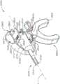
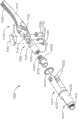
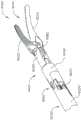
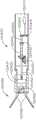
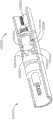
图1示出根据至少一个实施方案的包括柄部和多个轴组件的外科系统,其中轴组件中的每个能够选择性地附接到柄部;1 illustrates a surgical system including a handle and a plurality of shaft assemblies, wherein each of the shaft assemblies is selectively attachable to the handle, according to at least one embodiment;
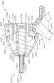
图2是图1的外科系统的柄部和轴组件中的一个轴组件的正视图;Figure 2 is a front view of one of the handle and shaft assemblies of the surgical system of Figure 1;
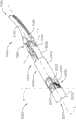
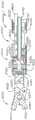
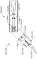
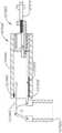
图3是图2的轴组件的局部剖面透视图;Figure 3 is a partial cutaway perspective view of the shaft assembly of Figure 2;
图4是图2的轴组件的另一局部剖面透视图;Fig. 4 is another partial cutaway perspective view of the shaft assembly of Fig. 2;
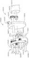
图5是图2的轴组件的局部分解图;Figure 5 is a partially exploded view of the shaft assembly of Figure 2;
图6是图2的轴组件的局部剖面正视图;Figure 6 is a partial cutaway front view of the shaft assembly of Figure 2;
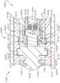
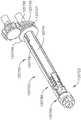
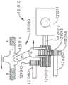
图7是图1的柄部的驱动模块的正视图;Figure 7 is a front view of the drive module of the handle of Figure 1;
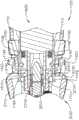
图8是图7的驱动模块的剖面透视图;8 is a cross-sectional perspective view of the drive module of FIG. 7;
图9是图7的驱动模块的端视图;Figure 9 is an end view of the drive module of Figure 7;
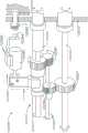
图10是处于锁定构型的图2的柄部和轴组件之间的互连的局部剖视图;10 is a partial cross-sectional view of the interconnection between the handle and shaft assembly of FIG. 2 in a locked configuration;
图11是处于解锁构型的图2的柄部和轴组件之间的互连的局部剖视图;11 is a partial cross-sectional view of the interconnection between the handle and shaft assembly of FIG. 2 in an unlocked configuration;
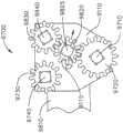
图12是图7的驱动模块的马达和减速齿轮组件的局部剖面透视图;12 is a partial cutaway perspective view of the motor and reduction gear assembly of the drive module of FIG. 7;
图13是图12的减速齿轮组件的端视图;Figure 13 is an end view of the reduction gear assembly of Figure 12;
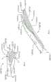
图14是处于打开构型的图2的轴组件的端部执行器的局部透视图;14 is a partial perspective view of the end effector of the shaft assembly of FIG. 2 in an open configuration;
图15是处于封闭构型的图14的端部执行器的局部透视图;Figure 15 is a partial perspective view of the end effector of Figure 14 in a closed configuration;
图16是在第一方向上进行关节运动的图14的端部执行器的局部透视图;16 is a partial perspective view of the end effector of FIG. 14 articulating in a first direction;
图17是在第二方向上进行关节运动的图14的端部执行器的局部透视图;17 is a partial perspective view of the end effector of FIG. 14 articulating in a second direction;
图18是在第一方向上旋转的图14的端部执行器的局部透视图;Figure 18 is a partial perspective view of the end effector of Figure 14 rotated in a first orientation;
图19是在第二方向上旋转的图14的端部执行器的局部透视图;Figure 19 is a partial perspective view of the end effector of Figure 14 rotated in a second direction;
图20是与图2的轴组件分离的图14的端部执行器的局部剖面透视图;Figure 20 is a partial cutaway perspective view of the end effector of Figure 14 separated from the shaft assembly of Figure 2;
图21是被示出为一些部件被移除的图14的端部执行器的分解图;Figure 21 is an exploded view of the end effector of Figure 14 shown with some components removed;
图22是图2的轴组件的远侧附接部分的分解图;Figure 22 is an exploded view of the distal attachment portion of the shaft assembly of Figure 2;
图22A是被示出为一些部件被移除的图2的轴组件的远侧部分的分解图;22A is an exploded view of the distal portion of the shaft assembly of FIG. 2 shown with some components removed;
图23是与图2的轴组件分离的图14的端部执行器的另一局部剖面透视图;Figure 23 is another partial cutaway perspective view of the end effector of Figure 14 separated from the shaft assembly of Figure 2;
图24是附接到图2的轴组件的图14的端部执行器的局部剖面透视图;24 is a partial cutaway perspective view of the end effector of FIG. 14 attached to the shaft assembly of FIG. 2;
图25是附接到图2的轴组件的图14的端部执行器的局部剖面透视图;25 is a partial cutaway perspective view of the end effector of FIG. 14 attached to the shaft assembly of FIG. 2;
图26是附接到图2的轴组件的图14的端部执行器的另一局部剖面透视图;Figure 26 is another partial cutaway perspective view of the end effector of Figure 14 attached to the shaft assembly of Figure 2;
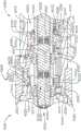
图27是附接到图2的轴组件的图14的端部执行器的局部剖视图,该局部剖视图示出了端部执行器的第一离合器、第二离合器和第三离合器;27 is a partial cross-sectional view of the end effector of FIG. 14 attached to the shaft assembly of FIG. 2, the partial cross-sectional view showing a first clutch, a second clutch, and a third clutch of the end effector;
图28示出了处于未致动状态的图27的第一离合器;Figure 28 shows the first clutch of Figure 27 in an unactuated state;
图29示出了处于致动状态的图27的第一离合器;Figure 29 shows the first clutch of Figure 27 in an actuated state;
图30示出了处于未致动状态的图27的第二离合器;FIG. 30 shows the second clutch of FIG. 27 in an unactuated state;
图31示出了处于致动状态的图27的第二离合器;Figure 31 shows the second clutch of Figure 27 in an actuated state;
图32示出了处于未致动状态的图27的第三离合器;FIG. 32 shows the third clutch of FIG. 27 in an unactuated state;
图33示出了处于致动状态的图27的第三离合器;Figure 33 shows the third clutch of Figure 27 in an actuated state;
图34示出了处于其未致动状态的图27的第二离合器和第三离合器以及锁定到图2的轴组件的图14的端部执行器;34 shows the second and third clutches of FIG. 27 and the end effector of FIG. 14 locked to the shaft assembly of FIG. 2 in their unactuated state;
图35示出了处于其未致动状态的图27的第二离合器和处于其致动状态的图27的第三离合器;Figure 35 shows the second clutch of Figure 27 in its unactuated state and the third clutch of Figure 27 in its actuated state;
图36示出了处于其致动状态的图27的第二离合器和第三离合器以及从图2的轴组件解锁的图14的端部执行器;Figure 36 shows the second and third clutches of Figure 27 in their actuated states and the end effector of Figure 14 unlocked from the shaft assembly of Figure 2;
图37是根据至少一个另选实施方案的轴组件的局部剖视图,该轴组件包括被配置成能够检测图27的第一离合器、第二离合器和第三离合器的状态的传感器;37 is a partial cross-sectional view of a shaft assembly including sensors configured to detect the status of the first, second, and third clutches of FIG. 27, according to at least one alternative embodiment;
图38是根据至少一个另选实施方案的轴组件的局部剖视图,该轴组件包括被配置成能够检测图27的第一离合器、第二离合器和第三离合器的状态的传感器;38 is a partial cross-sectional view of a shaft assembly including sensors configured to detect the status of the first, second, and third clutches of FIG. 27, according to at least one alternative embodiment;
图39示出了根据至少一个另选实施方案的处于其未致动状态的图38的第一离合器和第二离合器以及传感器;FIG. 39 shows the first and second clutches and sensors of FIG. 38 in their unactuated state according to at least one alternative embodiment;
图40示出了根据至少一个另选实施方案的处于其未致动状态的图38的第二离合器和第三离合器以及传感器;FIG. 40 shows the second and third clutches and sensors of FIG. 38 in their unactuated state according to at least one alternative embodiment;
图41是根据至少一个实施方案的轴组件的局部剖视图;41 is a partial cross-sectional view of a shaft assembly according to at least one embodiment;
图42是包括被示出为处于未致动状态的离合器的图41的轴组件的局部剖视图;42 is a partial cross-sectional view of the shaft assembly of FIG. 41 including the clutch shown in an unactuated state;
图43是示出了离合器处于致动状态的图41的轴组件的局部剖视图;43 is a partial cross-sectional view of the shaft assembly of FIG. 41 showing the clutch in an actuated state;
图44是根据至少一个实施方案的包括被示出为处于未致动状态的第一离合器和第二离合器的轴组件的局部剖视图;44 is a partial cross-sectional view of a shaft assembly including a first clutch and a second clutch shown in an unactuated state, according to at least one embodiment;
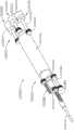
图45是图7的柄部驱动模块和图1的外科系统的轴组件中的一个的透视图;Figure 45 is a perspective view of the handle drive module of Figure 7 and one of the shaft assemblies of the surgical system of Figure 1;
图46是图7的柄部驱动模块和图45的轴组件的另一透视图;Figure 46 is another perspective view of the handle drive module of Figure 7 and the shaft assembly of Figure 45;
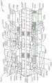
图47是附接到图1的柄部的图45的轴组件的局部剖视图;Figure 47 is a partial cross-sectional view of the shaft assembly of Figure 45 attached to the handle of Figure 1;
图48是附接到图1的柄部的图45的轴组件的局部剖视图;Figure 48 is a partial cross-sectional view of the shaft assembly of Figure 45 attached to the handle of Figure 1;
图49是图45的轴组件的局部剖视透视图;Figure 49 is a partial cutaway perspective view of the shaft assembly of Figure 45;
图50是图1的外科器械的控制系统的示意图。FIG. 50 is a schematic diagram of the control system of the surgical instrument of FIG. 1 .
图51是根据至少一个实施方案的轴组件的透视图;Figure 51 is a perspective view of a shaft assembly according to at least one embodiment;
图52是被示出为一些部件被移除的图51的轴组件的透视图;Figure 52 is a perspective view of the shaft assembly of Figure 51 shown with some components removed;
图53是图51的轴组件的端部执行器的透视图;Figure 53 is a perspective view of the end effector of the shaft assembly of Figure 51;
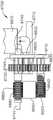
图54是图51的轴组件的驱动组件的透视图;Figure 54 is a perspective view of the drive assembly of the shaft assembly of Figure 51;
图55是图54的驱动组件的另一个透视图;Figure 55 is another perspective view of the drive assembly of Figure 54;
图56是图54的驱动组件的局部平面图;Figure 56 is a partial plan view of the drive assembly of Figure 54;
图57是根据至少一个另选实施方案的驱动组件的局部剖视图;57 is a partial cross-sectional view of a drive assembly according to at least one alternative embodiment;
图58是被示出为处于切换构型的一些部件被移除的图54的驱动组件的平面图;58 is a plan view of the drive assembly of FIG. 54 shown in a switched configuration with some components removed;
图59是被示出为处于驱动构型的一些部件被移除的图54的驱动组件的正视图;Figure 59 is a front view of the drive assembly of Figure 54 shown in a drive configuration with some components removed;
图60是处于驱动构型的图54的驱动组件的俯视图;Figure 60 is a top view of the drive assembly of Figure 54 in a drive configuration;
图61是处于切换构型的图54的驱动组件的俯视图;Figure 61 is a top view of the drive assembly of Figure 54 in a switched configuration;
图62是图53的端部执行器的局部透视剖视图;Figure 62 is a partial perspective cross-sectional view of the end effector of Figure 53;
图63是图53的端部执行器的局部透视剖视图;Figure 63 is a partial perspective cross-sectional view of the end effector of Figure 53;
图64是处于关节运动驱动模式的图53的端部执行器的局部俯视剖视图;64 is a partial top cross-sectional view of the end effector of FIG. 53 in an articulation drive mode;
图65是处于关节运动构型的图53的端部执行器的局部俯视剖视图;65 is a partial top cross-sectional view of the end effector of FIG. 53 in an articulating configuration;
图66是处于旋转驱动模式的图53的端部执行器的局部俯视剖视图;Figure 66 is a partial top cross-sectional view of the end effector of Figure 53 in a rotational drive mode;
图67是处于旋转构型的图53的端部执行器的局部俯视剖视图;67 is a partial top cross-sectional view of the end effector of FIG. 53 in a rotated configuration;
图68是处于钳口打开/闭合驱动模式的图53的端部执行器的局部俯视剖视图;68 is a partial top cross-sectional view of the end effector of FIG. 53 in a jaw open/close drive mode;
图69是处于闭合构型的图53的端部执行器的局部俯视剖视图;Figure 69 is a partial top cross-sectional view of the end effector of Figure 53 in a closed configuration;
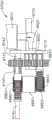
图70是根据至少一个实施方案的轴组件的驱动组件的透视图;Figure 70 is a perspective view of a drive assembly of a shaft assembly in accordance with at least one embodiment;
图71是处于打开构型的图70的轴组件的端部执行器的透视图;Figure 71 is a perspective view of the end effector of the shaft assembly of Figure 70 in an open configuration;
图72是图71的端部执行器的局部透视剖视图;Figure 72 is a partial perspective cross-sectional view of the end effector of Figure 71;
图73是图71的端部执行器的另一个局部透视剖视图;Figure 73 is another partial perspective cross-sectional view of the end effector of Figure 71;
图74是处于关节运动驱动模式的图71的端部执行器的局部俯视剖视图;74 is a partial top cross-sectional view of the end effector of FIG. 71 in an articulation drive mode;
图75是处于关节运动构型的图71的端部执行器的局部俯视剖视图;75 is a partial top cross-sectional view of the end effector of FIG. 71 in an articulated configuration;
图76是处于旋转驱动模式的图71的端部执行器的局部俯视剖视图;76 is a partial top cross-sectional view of the end effector of FIG. 71 in a rotational drive mode;
图77是处于旋转构型的图71的端部执行器的局部俯视剖视图;Figure 77 is a partial top cross-sectional view of the end effector of Figure 71 in a rotated configuration;
图78是处于钳口打开/闭合驱动模式的图71的端部执行器的局部俯视剖视图;78 is a partial top cross-sectional view of the end effector of FIG. 71 in a jaw open/close drive mode;
图79是处于闭合构型的图71的端部执行器的局部俯视剖视图;Figure 79 is a partial top cross-sectional view of the end effector of Figure 71 in a closed configuration;
图80是根据至少一个实施方案的驱动轴的局部俯视剖视图;80 is a partial top cross-sectional view of a drive shaft in accordance with at least one embodiment;
图81是处于关节运动构型的图80的驱动轴的局部俯视剖视图;81 is a partial top cross-sectional view of the drive shaft of FIG. 80 in an articulating configuration;
图82是根据至少一个实施方案的外科器械的轴组件的远侧端部的局部透视图;82 is a partial perspective view of a distal end of a shaft assembly of a surgical instrument according to at least one embodiment;
图83是示出延伸的锁定元件的图82的远侧端部的局部透视图;Figure 83 is a partial perspective view of the distal end of Figure 82 showing an extended locking element;
图84是根据至少一个实施方案的外科器械的轴和柄部之间的互连件的局部透视图;84 is a partial perspective view of an interconnect between a shaft and a handle of a surgical instrument according to at least one embodiment;
图85是包括电动马达输入端和可切换传输装置的外科器械的驱动系统的局部透视图;85 is a partial perspective view of a drive system of a surgical instrument including an electric motor input and a switchable transmission;
图86是包括电动马达输入端和可切换传输装置的外科器械的驱动系统的局部透视图;86 is a partial perspective view of a drive system of a surgical instrument including an electric motor input and a switchable transmission;
图86A示出了处于第一构型的图86的传输装置;Figure 86A shows the transfer device of Figure 86 in a first configuration;
图86B示出了被切换成第二构型的图86的传输装置;Figure 86B shows the transmission device of Figure 86 switched to a second configuration;
图86C示出了处于第二构型的图86的传输装置;Figure 86C shows the transfer device of Figure 86 in a second configuration;
图87A是根据至少一个实施方案的包括可切换输入端的外科器械的驱动系统的局部剖视图;87A is a partial cross-sectional view of a drive system of a surgical instrument including a switchable input, according to at least one embodiment;
图87B示出了处于打开构型的图87A的外科器械;Figure 87B shows the surgical instrument of Figure 87A in an open configuration;
图87C示出了处于非关节运动构型的图87A的外科器械;Figure 87C shows the surgical instrument of Figure 87A in a non-articulating configuration;
图87D示出了处于关节运动构型的图87A的外科器械;Figure 87D shows the surgical instrument of Figure 87A in an articulating configuration;
图88A是根据至少一个实施方案的包括传输装置的外科器械的驱动系统的局部剖视图;88A is a partial cross-sectional view of a drive system of a surgical instrument including a transfer device, according to at least one embodiment;
图88B示出了处于第二构型的传输装置;Figure 88B shows the transfer device in a second configuration;
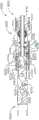
图89是根据至少一个实施方案的外科器械的驱动系统的局部剖视图;89 is a partial cross-sectional view of a drive system of a surgical instrument according to at least one embodiment;
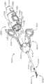
图90是根据至少一个实施方案的外科器械的驱动系统的局部透视图;Figure 90 is a partial perspective view of a drive system of a surgical instrument according to at least one embodiment;
图91是图90的驱动系统的细部图;Figure 91 is a detailed view of the drive system of Figure 90;
图92是根据至少一个实施方案的柔性驱动轴的透视图;Figure 92 is a perspective view of a flexible drive shaft according to at least one embodiment;
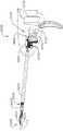
图93为图90的外科器械的局部透视图;Figure 93 is a partial perspective view of the surgical instrument of Figure 90;
图94是根据至少一个实施方案的外科器械系统的局部透视图;Figure 94 is a partial perspective view of a surgical instrument system according to at least one embodiment;
图95A是图94的外科器械系统的驱动系统的侧视图;Figure 95A is a side view of the drive system of the surgical instrument system of Figure 94;
图95B是图95A的驱动系统的端视图;Figure 95B is an end view of the drive system of Figure 95A;
图96是根据至少一个实施方案的外科器械的附接到第一柄部的驱动系统的局部透视图;96 is a partial perspective view of a drive system of a surgical instrument attached to a first handle according to at least one embodiment;
图97是附接到第二柄部的图96的驱动系统的局部透视图;Figure 97 is a partial perspective view of the drive system of Figure 96 attached to the second handle;
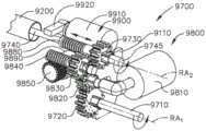
图98是根据至少一个实施方案的外科器械的驱动系统的局部剖视图;98 is a partial cross-sectional view of a drive system of a surgical instrument according to at least one embodiment;
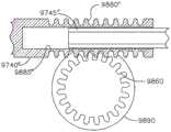
图99是图98的外科器械的一部分的端视图;Figure 99 is an end view of a portion of the surgical instrument of Figure 98;
图100是根据至少一个实施方案的外科器械的一部分的剖面端视图;Figure 100 is a cross-sectional end view of a portion of a surgical instrument according to at least one embodiment;
图101是图98的驱动系统的透视图;Figure 101 is a perspective view of the drive system of Figure 98;
图102是根据至少一个实施方案的被示出为一些部件被移除的驱动系统的局部透视图;102 is a partial perspective view of a drive system shown with some components removed, according to at least one embodiment;
图103是图100的外科器械的局部透视图;Figure 103 is a partial perspective view of the surgical instrument of Figure 100;
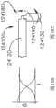
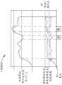
图104是示出了外科器械的端部执行器的旋转和关节运动的曲线图;Figure 104 is a graph showing rotation and articulation of an end effector of a surgical instrument;
图105是包括可旋转和可关节运动的端部执行器的轴组件的局部俯视图;Figure 105 is a partial top view of a shaft assembly including a rotatable and articulatable end effector;
图106是示出了在至少一种情况下的图105的端部执行器的旋转和关节运动的曲线图;Figure 106 is a graph showing rotation and articulation of the end effector of Figure 105 under at least one condition;
图107是图105的轴组件的另一个局部俯视图;Figure 107 is another partial top view of the shaft assembly of Figure 105;
图108是示出了在至少一种情况下的图105的端部执行器的旋转和关节运动的曲线图;Figure 108 is a graph showing rotation and articulation of the end effector of Figure 105 under at least one condition;
图109是根据至少一个实施方案的外科器械的局部剖视图;Figure 109 is a partial cross-sectional view of a surgical instrument according to at least one embodiment;
图110是图109的外科器械的局部剖视图;Figure 110 is a partial cross-sectional view of the surgical instrument of Figure 109;
图111A是根据至少一个实施方案的包括可切换传输装置的外科器械的局部剖视图;111A is a partial cross-sectional view of a surgical instrument including a switchable transmission device, according to at least one embodiment;
图111B示出了处于第一构型的图111A的传输装置;Figure 111B shows the transport device of Figure 111A in a first configuration;
图111C示出了处于第二构型的图111B的传输装置;Figure 111C shows the transfer device of Figure 111B in a second configuration;
图112是根据至少一个实施方案的外科器械的局部透视图;Figure 112 is a partial perspective view of a surgical instrument according to at least one embodiment;
图113A是根据至少一个实施方案的包括轴组件和可拆卸端部执行器的外科器械的局部剖视图;113A is a partial cross-sectional view of a surgical instrument including a shaft assembly and a detachable end effector, according to at least one embodiment;
图113B示出了处于附接状态的端部执行器;Figure 113B shows the end effector in an attached state;
图114是根据至少一个实施方案的驱动轴互连件的局部剖视图;114 is a partial cross-sectional view of a drive shaft interconnect according to at least one embodiment;
图115是根据至少一个实施方案的包括端部执行器和关节运动系统的轴组件的局部剖视图;115 is a partial cross-sectional view of a shaft assembly including an end effector and an articulation system, according to at least one embodiment;
图116是图115的轴组件的局部剖视图;Figure 116 is a partial cross-sectional view of the shaft assembly of Figure 115;
图117是图115的关节运动系统的局部分解图;Figure 117 is a partially exploded view of the articulation system of Figure 115;
图118是根据至少一个实施方案的包括关节运动系统的外科器械的局部剖视图;118 is a partial cross-sectional view of a surgical instrument including an articulation system, according to at least one embodiment;
图119是处于关节运动构型的图118的外科器械的局部剖视图;Figure 119 is a partial cross-sectional view of the surgical instrument of Figure 118 in an articulating configuration;
图120是根据至少一个实施方案的外科器械的关节运动系统的局部平面图;120 is a partial plan view of an articulation system of a surgical instrument according to at least one embodiment;
图121是根据至少一个实施方案的外科器械的关节运动系统的局部平面图;121 is a partial plan view of an articulation system of a surgical instrument according to at least one embodiment;
图122是根据至少一个实施方案的外科器械的关节运动系统的局部平面图;122 is a partial plan view of an articulation system of a surgical instrument according to at least one embodiment;
图123是根据至少一个实施方案的包括能够抓持和解剖的钳口组件的外科器械的局部剖视图;123 is a partial cross-sectional view of a surgical instrument including a jaw assembly capable of grasping and dissecting, according to at least one embodiment;
图124是示出根据至少一个实施方案的图123的钳口组件的力、速度和取向的曲线图;Figure 124 is a graph showing force, velocity and orientation of the jaw assembly of Figure 123, according to at least one embodiment;
图125是用于切割组织的双极夹钳的局部透视图;Figure 125 is a partial perspective view of a bipolar clamp for cutting tissue;
图126是图125的双极夹钳的透视图;Figure 126 is a perspective view of the bipolar clamp of Figure 125;
图127是示出根据至少一个实施方案的图125的双极夹钳的钳口的力和速度的曲线图;并且Figure 127 is a graph showing force and velocity of the jaws of the bipolar clamp of Figure 125, according to at least one embodiment; and
图128是示出根据至少一个实施方案的图125的双极夹钳的操作的另一个曲线图。128 is another graph illustrating operation of the bipolar clamp of FIG. 125, according to at least one embodiment.
在所述若干视图中,对应的参考符号指示对应的部件。本文所述的范例以一种形式示出了本发明的各种实施方案,且这种范例不应被解释为以任何方式限制本发明的范围。Corresponding reference characters indicate corresponding parts throughout the several views. The exemplifications described herein illustrate various embodiments of the invention in one form, and such exemplifications should not be construed to limit the scope of the invention in any way.
具体实施方式Detailed ways
本专利申请的申请人拥有于2018年8月24日提交且各自全文以引用方式并入本文的以下美国专利申请:The applicant of this patent application owns the following U.S. patent applications filed on August 24, 2018, each of which is incorporated herein by reference in its entirety:
-名称为“SURGICAL SUTURING INSTRUMENT CONFIGURED TO MANIPULATE TISSUEUSING MECHANICAL AND ELECTRICAL POWER”的美国专利申请序列号16/112,129;- US Patent Application Serial No. 16/112,129 entitled "SURGICAL SUTURING INSTRUMENT CONFIGURED TO MANIPULATE TISSUEUSING MECHANICAL AND ELECTRICAL POWER";
-名称为“SURGICAL SUTURING INSTRUMENT COMPRISING A CAPTURE WIDTH WHICHIS LARGER THAN TROCAR DIAMETER”的美国专利申请序列号16/112,155;- US Patent Application Serial No. 16/112,155 entitled "SURGICAL SUTURING INSTRUMENT COMPRISING A CAPTURE WIDTH WHICHIS LARGER THAN TROCAR DIAMETER";
-名称为“SURGICAL SUTURING INSTRUMENT COMPRISING A NON-CIRCULARNEEDLE”的美国专利申请序列号16/112,168;- US Patent Application Serial No. 16/112,168 entitled "SURGICAL SUTURING INSTRUMENT COMPRISING A NON-CIRCULARNEEDLE";
-名称为“ELECTRICAL POWER OUTPUT CONTROL BASED ON MECHANICAL FORCES”的美国专利申请序列号16/112,180;- US Patent Application Serial No. 16/112,180 entitled "ELECTRICAL POWER OUTPUT CONTROL BASED ON MECHANICAL FORCES";
-名称为“REACTIVE ALGORITHM FOR SURGICAL SYSTEM”的美国专利申请序列号16/112,193;- US Patent Application Serial No. 16/112,193 entitled "REACTIVE ALGORITHM FOR SURGICAL SYSTEM";
-名称为“SURGICAL INSTRUMENT COMPRISING AN ADAPTIVE ELECTRICAL SYSTEM”的美国专利申请序列号16/112,099;- US Patent Application Serial No. 16/112,099 entitled "SURGICAL INSTRUMENT COMPRISING AN ADAPTIVE ELECTRICAL SYSTEM";
-名称为“CONTROL SYSTEM ARRANGEMENTS FOR A MODULAR SURGICALINSTRUMENT”的美国专利申请序列号16/112,112;- US Patent Application Serial No. 16/112,112 entitled "CONTROL SYSTEM ARRANGEMENTS FOR A MODULAR SURGICALINSTRUMENT";
-名称为“ADAPTIVE CONTROL PROGRAMS FOR A SURGICAL SYSTEM COMPRISINGMORE THAN ONE TYPE OF CARTRIDGE”的美国专利申请序列号16/112,119;- US Patent Application Serial No. 16/112,119 entitled "ADAPTIVE CONTROL PROGRAMS FOR A SURGICAL SYSTEM COMPRISINGMORE THAN ONE TYPE OF CARTRIDGE";
-名称为“SURGICAL INSTRUMENT SYSTEMS COMPRISING BATTERY ARRANGEMENTS”的美国专利申请序列号16/112,097;- US Patent Application Serial No. 16/112,097 entitled "SURGICAL INSTRUMENT SYSTEMS COMPRISING BATTERY ARRANGEMENTS";
-名称为“SURGICAL INSTRUMENT SYSTEMS COMPRISING HANDLE ARRANGEMENTS”的美国专利申请序列号16/112,109;- US Patent Application Serial No. 16/112,109 entitled "SURGICAL INSTRUMENT SYSTEMS COMPRISING HANDLE ARRANGEMENTS";
-名称为“SURGICAL INSTRUMENT SYSTEMS COMPRISING FEEDBACK MECHANISMS”的美国专利申请序列号16/112,114;- US Patent Application Serial No. 16/112,114 entitled "SURGICAL INSTRUMENT SYSTEMS COMPRISING FEEDBACK MECHANISMS";
-名称为“SURGICAL INSTRUMENT SYSTEMS COMPRISING LOCKOUT MECHANISMS”的美国专利申请序列号16/112,117;- US Patent Application Serial No. 16/112,117 entitled "SURGICAL INSTRUMENT SYSTEMS COMPRISING LOCKOUT MECHANISMS";
-名称为“SURGICAL INSTRUMENTS COMPRISING A LOCKABLE END EFFECTORSOCKET”的美国专利申请序列号16/112,095;- US Patent Application Serial No. 16/112,095 entitled "SURGICAL INSTRUMENTS COMPRISING A LOCKABLE END EFFECTORSOCKET";
-名称为“SURGICAL INSTRUMENTS COMPRISING A SHIFTING MECHANISM”的美国专利申请序列号16/112,121;- US Patent Application Serial No. 16/112,121 entitled "SURGICAL INSTRUMENTS COMPRISING A SHIFTING MECHANISM";
-名称为“SURGICAL INSTRUMENTS COMPRISING A SYSTEM FOR ARTICULATION ANDROTATION COMPENSATION”的美国专利申请序列号16/112,151;- US Patent Application Serial No. 16/112,151 entitled "SURGICAL INSTRUMENTS COMPRISING A SYSTEM FOR ARTICULATION ANDROTATION COMPENSATION";
-名称为“SURGICAL INSTRUMENTS COMPRISING AN ARTICULATION DRIVE THATPROVIDES FOR HIGH ARTICULATION ANGLES”的美国专利申请序列号16/112,226;- US Patent Application Serial No. 16/112,226 entitled "SURGICAL INSTRUMENTS COMPRISING AN ARTICULATION DRIVE THATPROVIDES FOR HIGH ARTICULATION ANGLES";
-名称为“SURGICAL DISSECTORS AND MANUFACTURING TECHNIQUES”的美国专利申请序列号16/112,062;- US Patent Application Serial No. 16/112,062 entitled "SURGICAL DISSECTORS AND MANUFACTURING TECHNIQUES";
-名称为“SURGICAL DISSECTORS CONFIGURED TO APPLY MECHANICAL ANDELECTRICAL ENERGY”的美国专利申请序列号16/112,098;- US Patent Application Serial No. 16/112,098 entitled "SURGICAL DISSECTORS CONFIGURED TO APPLY MECHANICAL ANDELECTRICAL ENERGY";
-名称为“SURGICAL CLIP APPLIER CONFIGURED TO STORE CLIPS IN A STOREDSTATE”的美国专利申请序列号16/112,237;- US Patent Application Serial No. 16/112,237 entitled "SURGICAL CLIP APPLIER CONFIGURED TO STORE CLIPS IN A STOREDSTATE";
-名称为“SURGICAL CLIP APPLIER COMPRISING AN EMPTY CLIP CARTRIDGELOCKOUT”的美国专利申请序列号16/112,245;- US Patent Application Serial No. 16/112,245 entitled "SURGICAL CLIP APPLIER COMPRISING AN EMPTY CLIP CARTRIDGELOCKOUT";
-名称为“SURGICAL CLIP APPLIER COMPRISING AN AUTOMATIC CLIP FEEDINGSYSTEM”的美国专利申请序列号16/112,249;- US Patent Application Serial No. 16/112,249 entitled "SURGICAL CLIP APPLIER COMPRISING AN AUTOMATIC CLIP FEEDINGSYSTEM";
-名称为“SURGICAL CLIP APPLIER COMPRISING ADAPTIVE FIRING CONTROL”的美国专利申请序列号16/112,253;以及- US Patent Application Serial No. 16/112,253 entitled "SURGICAL CLIP APPLIER COMPRISING ADAPTIVE FIRING CONTROL"; and
-名称为“SURGICAL CLIP APPLIER COMPRISING ADAPTIVE CONTROL IN RESPONSETO A STRAIN GAUGE CIRCUIT”的美国专利申请序列号16/112,257。- US Patent Application Serial No. 16/112,257 entitled "SURGICAL CLIP APPLIER COMPRISING ADAPTIVE CONTROL IN RESPONSETO A STRAIN GAUGE CIRCUIT".
本专利申请的申请人拥有于2018年5月1日提交且各自全文以引用方式并入本文的以下美国专利申请:The applicant of this patent application owns the following US patent applications filed on May 1, 2018, each of which is incorporated herein by reference in its entirety:
-名称为“SURGICAL SUTURING SYSTEMS”的美国临时专利申请序列号62/665,129;- US Provisional Patent Application Serial No. 62/665,129 entitled "SURGICAL SUTURING SYSTEMS";
-名称为“SURGICAL INSTRUMENTS COMPRISING CONTROL SYSTEMS”的美国专利申请序列号62/665,139;- US Patent Application Serial No. 62/665,139 entitled "SURGICAL INSTRUMENTS COMPRISING CONTROL SYSTEMS";
-名称为“SURGICAL INSTRUMENTS COMPRISING HANDLE ARRANGEMENTS”的美国临时专利申请序列号62/665,177;- US Provisional Patent Application Serial No. 62/665,177 entitled "SURGICAL INSTRUMENTS COMPRISING HANDLE ARRANGEMENTS";
-名称为“MODULAR SURGICAL INSTRUMENTS”的美国临时专利申请序列号62/665,128;- US Provisional Patent Application Serial No. 62/665,128 entitled "MODULAR SURGICAL INSTRUMENTS";
-名称为“SURGICAL DISSECTORS”的美国临时专利申请序列号62/665,192;以及- US Provisional Patent Application Serial No. 62/665,192 entitled "SURGICAL DISSECTORS"; and
-名称为“SURGICAL CLIP APPLIER”的美国临时专利申请序列号62/665,134;- US Provisional Patent Application Serial No. 62/665,134 entitled "SURGICAL CLIP APPLIER";
本专利申请的申请人拥有于2018年2月28日提交且各自全文以引用方式并入本文的以下美国专利申请:The applicant of this patent application owns the following US patent applications filed on February 28, 2018, each of which is incorporated herein by reference in its entirety:
-名称为“SURGICAL INSTRUMENT WITH REMOTE RELEASE”的美国专利申请序列号15/908,021;- US Patent Application Serial No. 15/908,021 entitled "SURGICAL INSTRUMENT WITH REMOTE RELEASE";
-名称为“SURGICAL INSTRUMENT HAVING DUAL ROTATABLE MEMBERS TO EFFECTDIFFERENT TYPES OF END EFFECTOR MOVEMENT”的美国专利申请序列号15/908,012;- US Patent Application Serial No. 15/908,012 entitled "SURGICAL INSTRUMENT HAVING DUAL ROTATABLE MEMBERS TO EFFECTDIFFERENT TYPES OF END EFFECTOR MOVEMENT";
-名称为“SURGICAL INSTRUMENT WITH ROTARY DRIVE SELECTIVELY ACTUATINGMULTIPLE END EFFECTOR FUNCTIONS”的美国专利申请序列号15/908,040;- US Patent Application Serial No. 15/908,040 entitled "SURGICAL INSTRUMENT WITH ROTARY DRIVE SELECTIVELY ACTUATINGMULTIPLE END EFFECTOR FUNCTIONS";
-名称为“SURGICAL INSTRUMENT WITH ROTARY DRIVE SELECTIVELY ACTUATINGMULTIPLE END EFFECTOR FUNCTIONS”的美国专利申请序列号15/908,057;- US Patent Application Serial No. 15/908,057 entitled "SURGICAL INSTRUMENT WITH ROTARY DRIVE SELECTIVELY ACTUATINGMULTIPLE END EFFECTOR FUNCTIONS";
-名称为“SURGICAL INSTRUMENT WITH MODULAR POWER SOURCES”的美国专利申请序列号15/908,058;以及- US Patent Application Serial No. 15/908,058 entitled "SURGICAL INSTRUMENT WITH MODULAR POWER SOURCES"; and
-名称为“SURGICAL INSTRUMENT WITH SENSOR AND/OR CONTROL SYSTEMS”的美国专利申请序列号15/908,143。- US Patent Application Serial No. 15/908,143 entitled "SURGICAL INSTRUMENT WITH SENSOR AND/OR CONTROL SYSTEMS".
本专利申请的申请人拥有于2017年10月30日提交且各自全文以引用方式并入本文的以下美国专利申请:The applicant of this patent application owns the following US patent applications filed on October 30, 2017, each of which is hereby incorporated by reference in its entirety:
-名称为“SURGICAL INSTRUMENT WITH REMOTE RELEASE”的美国专利申请序列号62/578,793;- US Patent Application Serial No. 62/578,793 entitled "SURGICAL INSTRUMENT WITH REMOTE RELEASE";
-名称为“SURGICAL INSTRUMENT HAVING DUAL ROTATABLE MEMBERS TO EFFECTDIFFERENT TYPES OF END EFFECTOR MOVEMENT”的美国专利申请序列号62/578,804;- US Patent Application Serial No. 62/578,804 entitled "SURGICAL INSTRUMENT HAVING DUAL ROTATABLE MEMBERS TO EFFECTDIFFERENT TYPES OF END EFFECTOR MOVEMENT";
-名称为“SURGICAL INSTRUMENT WITH ROTARY DRIVE SELECTIVELY ACTUATINGMULTIPLE END EFFECTOR FUNCTIONS”的美国专利申请序列号62/578,817;- US Patent Application Serial No. 62/578,817 entitled "SURGICAL INSTRUMENT WITH ROTARY DRIVE SELECTIVELY ACTUATINGMULTIPLE END EFFECTOR FUNCTIONS";
-名称为“SURGICAL INSTRUMENT WITH ROTARY DRIVE SELECTIVELY ACTUATINGMULTIPLE END EFFECTOR FUNCTIONS”的美国专利申请序列号62/578,835;- US Patent Application Serial No. 62/578,835 entitled "SURGICAL INSTRUMENT WITH ROTARY DRIVE SELECTIVELY ACTUATINGMULTIPLE END EFFECTOR FUNCTIONS";
-名称为“SURGICAL INSTRUMENT WITH MODULAR POWER SOURCES”的美国专利申请序列号62/578,844;以及- US Patent Application Serial No. 62/578,844 entitled "SURGICAL INSTRUMENT WITH MODULAR POWER SOURCES"; and
-名称为“SURGICAL INSTRUMENT WITH SENSOR AND/OR CONTROL SYSTEMS”的美国专利申请序列号62/578,855。- US Patent Application Serial No. 62/578,855 entitled "SURGICAL INSTRUMENT WITH SENSOR AND/OR CONTROL SYSTEMS".
本专利申请的申请人拥有于2017年12月28日提交的以下美国临时专利申请,这些临时专利申请中的每个的公开内容以引用方式全文并入本文:The applicant of this patent application has the following US provisional patent applications filed on December 28, 2017, the disclosures of each of these provisional patent applications are incorporated herein by reference in their entirety:
-名称为“INTERACTIVE SURGICAL PLATFORM”的美国临时专利申请序列号62/611,341;- US Provisional Patent Application Serial No. 62/611,341 entitled "INTERACTIVE SURGICAL PLATFORM";
-名称为“CLOUD-BASED MEDICAL ANALYTICS”的美国临时专利申请序列号62/611,340;以及- US Provisional Patent Application Serial No. 62/611,340 entitled "CLOUD-BASED MEDICAL ANALYTICS"; and
-名称为“ROBOT ASSISTED SURGICAL PLATFORM”的美国临时专利申请序列号62/611,339。- US Provisional Patent Application Serial No. 62/611,339 entitled "ROBOT ASSISTED SURGICAL PLATFORM".
本专利申请的申请人拥有于2018年3月28日提交的以下美国临时专利申请,这些临时专利申请中的每个以引用方式全文并入本文:The applicant of the present patent application has the following U.S. Provisional Patent Applications filed on March 28, 2018, each of which is incorporated herein by reference in its entirety:
-名称为“INTERACTIVE SURGICAL SYSTEMS WITH encrypted COMMUNICATIONCAPABILITIES”的美国临时专利申请序列号62/649,302;- U.S. Provisional Patent Application Serial No. 62/649,302 entitled "INTERACTIVE SURGICAL SYSTEMS WITH encrypted COMMUNICATIONCAPABILITIES";
-名称为“DATA STRIPPING METHOD TO INTERROGATE PATIENT RECORDS ANDCREATE ANONYMIZED RECORD”的美国临时专利申请序列号62/649,294;- US Provisional Patent Application Serial No. 62/649,294 entitled "DATA STRIPPING METHOD TO INTERROGATE PATIENT RECORDS ANDCREATE ANONYMIZED RECORD";
-名称为“SURGICAL HUB SITUATIONAL AWARENESS”的美国临时专利申请序列号62/649,300;- US Provisional Patent Application Serial No. 62/649,300 entitled "SURGICAL HUB SITUATIONAL AWARENESS";
-名称为“SURGICAL HUB SPATIAL AWARENESS TO DETERMINE DEVICES INOPERATING THEATER”的美国临时专利申请序列号62/649,309;- US Provisional Patent Application Serial No. 62/649,309 entitled "SURGICAL HUB SPATIAL AWARENESS TO DETERMINE DEVICES INOPERATING THEATER";
-名称为“COMPUTER IMPLEMENTED INTERACTIVE SURGICAL SYSTEMS”的美国临时专利申请序列号62/649,310;- US Provisional Patent Application Serial No. 62/649,310 entitled "COMPUTER IMPLEMENTED INTERACTIVE SURGICAL SYSTEMS";
-名称为“USE OF LASER LIGHT AND RED-GREEN-BLUE COLORATION TO DETERMINEPROPERTIES OF BACK SCATTERED LIGHT”的美国临时专利申请序列号62/649,291;- US Provisional Patent Application Serial No. 62/649,291 entitled "USE OF LASER LIGHT AND RED-GREEN-BLUE COLORATION TO DETERMINEPROPERTIES OF BACK SCATTERED LIGHT";
-名称为“ADAPTIVE CONTROL PROGRAM UPDATES FOR SURGICAL DEVICES”的美国临时专利申请序列号62/649,296;- U.S. Provisional Patent Application Serial No. 62/649,296 entitled "ADAPTIVE CONTROL PROGRAM UPDATES FOR SURGICAL DEVICES";
-名称为“CLOUD-BASED MEDICAL ANALYTICS FOR CUSTOMIZATION ANDRECOMMENDATIONS TO A USER”的美国临时专利申请序列号62/649,333;- US Provisional Patent Application Serial No. 62/649,333 entitled "CLOUD-BASED MEDICAL ANALYTICS FOR CUSTOMIZATION ANDRECOMMENDATIONS TO A USER";
-名称为“CLOUD-BASED MEDICAL ANALYTICS FOR SECURITY AND AUTHENTICATIONTRENDS AND REACTIVE MEASURES”的美国临时专利申请序列号62/649,327;- US Provisional Patent Application Serial No. 62/649,327 entitled "CLOUD-BASED MEDICAL ANALYTICS FOR SECURITY AND AUTHENTICATION TRENDS AND REACTIVE MEASURES";
-名称为“DATA HANDLING AND PRIORITIZATION IN A CLOUD ANALYTICSNETWORK”的美国临时专利申请序列号62/649,315;- US Provisional Patent Application Serial No. 62/649,315 entitled "DATA HANDLING AND PRIORITIZATION IN A CLOUD ANALYTICSNETWORK";
-名称为“CLOUD INTERFACE FOR COUPLED SURGICAL DEVICES”的美国临时专利申请序列号62/649,313;- US Provisional Patent Application Serial No. 62/649,313 entitled "CLOUD INTERFACE FOR COUPLED SURGICAL DEVICES";
-名称为“DRIVE ARRANGEMENTS FOR ROBOT-ASSISTED SURGICAL PLATFORMS”的美国临时专利申请序列号62/649,320;- US Provisional Patent Application Serial No. 62/649,320 entitled "DRIVE ARRANGEMENTS FOR ROBOT-ASSISTED SURGICAL PLATFORMS";
-名称为“AUTOMATIC TOOL ADJUSTMENTS FOR ROBOT-ASSISTED SURGICALPLATFORMS”的美国临时专利申请序列号62/649,307;以及- U.S. Provisional Patent Application Serial No. 62/649,307 entitled "AUTOMATIC TOOL ADJUSTMENTS FOR ROBOT-ASSISTED SURGICAL PLATFORMS"; and
-名称为“SENSING ARRANGEMENTS FOR Robot-Assisted Surgical PlatformS”的美国临时专利申请序列号62/649,323。- US Provisional Patent Application Serial No. 62/649,323 entitled "SENSING ARRANGEMENTS FOR Robot-Assisted Surgical PlatformS".
本专利申请的申请人拥有于2018年3月29日提交的以下美国专利申请,这些专利申请中的每个以引用方式全文并入本文:The applicant of this patent application has the following US patent applications filed on March 29, 2018, each of which is incorporated herein by reference in its entirety:
-名称为“INTERACTIVE SURGICAL SYSTEMS WITH encrypted COMMUNICATIONCAPABILITIES”的美国专利申请序列号15/940,641;- US Patent Application Serial No. 15/940,641 entitled "INTERACTIVE SURGICAL SYSTEMS WITH encrypted COMMUNICATION CAPABILITIES";
-名称为“INTERACTIVE SURGICAL SYSTEMS WITH CONDITION HANDLING OFDEVICES AND DATA CAPABILITIES”的美国专利申请序列号15/940,648;- US Patent Application Serial No. 15/940,648 entitled "INTERACTIVE SURGICAL SYSTEMS WITH CONDITION HANDLING OFDEVICES AND DATA CAPABILITIES";
-名称为“Surgical hub coordination of control and communication ofoperating room devices”的美国专利申请序列号15/940,656;- US Patent Application Serial No. 15/940,656 entitled "Surgical hub coordination of control and communication of operating room devices";
-名称为“Spatial awareness of surgical hubs in operating rooms”的美国专利申请序列号15/940,666;- US Patent Application Serial No. 15/940,666 entitled "Spatial awareness of surgical hubs in operating rooms";
-名称为“Cooperative utilization of data derived from secondarysources by intelligent surgical hubs”的美国专利申请序列号15/940,670;- US Patent Application Serial No. 15/940,670 entitled "Cooperative utilization of data derived from secondary sources by intelligent surgical hubs";
-名称为“Surgical hub control arrangements”的美国专利申请序列号15/940,677;- US Patent Application Serial No. 15/940,677 entitled "Surgical hub control arrangements";
-名称为“DATA STRIPPING METHOD TO INTERROGATE PATIENT RECORDS ANDCREATE ANONYMIZED RECORD”的美国专利申请序列号15/940,632;- US Patent Application Serial No. 15/940,632 entitled "DATA STRIPPING METHOD TO INTERROGATE PATIENT RECORDS ANDCREATE ANONYMIZED RECORD";
-名称为“COMMUNICATION HUB AND STORAGE DEVICE FOR STORING PARAMETERSAND STATUS OF A SURGICAL DEVICE TO BE SHAREd WITH CLOUD BASED ANALYTICSSYSTEMS”的美国专利申请序列号15/940,640;- US Patent Application Serial No. 15/940,640 entitled "COMMUNICATION HUB AND STORAGE DEVICE FOR STORING PARAMETERSAND STATUS OF A SURGICAL DEVICE TO BE SHAREed WITH CLOUD BASED ANALYTICSSYSTEMS";
-名称为“SELF DESCRIBING DATA PACKETS GENERATED AT AN ISSUINGINSTRUMENT”的美国专利申请序列号15/940,645;- US Patent Application Serial No. 15/940,645 entitled "SELF DESCRIBING DATA PACKETS GENERATED AT AN ISSUINGINSTRUMENT";
-名称为“DATA PAIRING TO INTERCONNECT A DEVICE MEASURED PARAMETER WITHAN OUTCOME”的美国专利申请序列号15/940,649;- US Patent Application Serial No. 15/940,649 entitled "DATA PAIRING TO INTERCONNECT A DEVICE MEASURED PARAMETER WITHAN OUTCOME";
-名称为“URGICAL HUB SITUATIONAL AWARENESS”的美国专利申请序列号15/940,654;- US Patent Application Serial No. 15/940,654 entitled "URGICAL HUB SITUATIONAL AWARENESS";
-名称为“SURGICAL SYSTEM DISTRIBUTED PROCESSING”的美国专利申请序列号15/940,663;- US Patent Application Serial No. 15/940,663 entitled "SURGICAL SYSTEM DISTRIBUTED PROCESSING";
-名称为“AGGREGATION AND REPORTING OF SURGICAL HUB DATA”的美国专利申请序列号15/940,668;- US Patent Application Serial No. 15/940,668 entitled "AGGREGATION AND REPORTING OF SURGICAL HUB DATA";
-名称为“SURGICAL HUB SPATIAL AWARENESS TO DETERMINE DEVICES INOPERATING THEATER”的美国临时专利申请序列号15/940,671;- US Provisional Patent Application Serial No. 15/940,671 entitled "SURGICAL HUB SPATIAL AWARENESS TO DETERMINE DEVICES INOPERATING THEATER";
-名称为“DISPLAY OF ALIGNMENT OF STAPLE CARTRIDGE TO PRIOR LINEARSTAPLE LINE”的美国专利申请序列号15/940,686;- US Patent Application Serial No. 15/940,686 entitled "DISPLAY OF ALIGNMENT OF STAPLE CARTRIDGE TO PRIOR LINEARSTAPLE LINE";
-名称为“STERILE FIELD INTERACTIVE CONTROL DISPLAYS”的美国专利申请序列号15/940,700;- US Patent Application Serial No. 15/940,700 entitled "STERILE FIELD INTERACTIVE CONTROL DISPLAYS";
-名称为“COMPUTER IMPLEMENTED INTERACTIVE SURGICAL SYSTEMS”的美国专利申请序列号15/940,629;- US Patent Application Serial No. 15/940,629 entitled "COMPUTER IMPLEMENTED INTERACTIVE SURGICAL SYSTEMS";
-名称为“USE OF LASER LIGHT AND RED-GREEN-BLUE COLORATION TO DETERMINEPROPERTIES OF BACK SCATTERED LIGHT”的美国临时专利申请序列号15/940,704;- U.S. Provisional Patent Application Serial No. 15/940,704 entitled "USE OF LASER LIGHT AND RED-GREEN-BLUE COLORATION TO DETERMINEPROPERTIES OF BACK SCATTERED LIGHT";
-名称为“CHARACTERIZATION OF TISSUE IRREGULARITIES THROUGH THE USE OFMONO-CHROMATIC LIGHT REFRACTIVITY”的美国临时专利申请序列号15/940,722;以及- U.S. Provisional Patent Application Serial No. 15/940,722 entitled "CHARACTERIZATION OF TISSUE IRREGULARITIES THROUGH THE USE OFMONO-CHROMATIC LIGHT REFRACTIVITY"; and
-名称为“DUAL CMOS ARRAY IMAGING”的美国专利申请序列号15/940,742。- US Patent Application Serial No. 15/940,742 entitled "DUAL CMOS ARRAY IMAGING".
本专利申请的申请人拥有于2018年3月29日提交的以下美国专利申请,这些专利申请中的每个以引用方式全文并入本文:The applicant of this patent application has the following US patent applications filed on March 29, 2018, each of which is incorporated herein by reference in its entirety:
-名称为“ADAPTIVE CONTROL PROGRAM UPDATES FOR SURGICAL DEVICES”的美国专利申请序列号15/940,636;- US Patent Application Serial No. 15/940,636 entitled "ADAPTIVE CONTROL PROGRAM UPDATES FOR SURGICAL DEVICES";
-名称为“ADAPTIVE CONTROL PROGRAM UPDATES FOR SURGICAL HUBS”的美国专利申请序列号15/940,653;- US Patent Application Serial No. 15/940,653 entitled "ADAPTIVE CONTROL PROGRAM UPDATES FOR SURGICAL HUBS";
-名称为“CLOUD-BASED MEDICAL ANALYTICS FOR CUSTOMIZATION ANDRECOMMENDATIONS TO A USER”的美国临时专利申请序列号15/940,660;- US Provisional Patent Application Serial No. 15/940,660 entitled "CLOUD-BASED MEDICAL ANALYTICS FOR CUSTOMIZATION ANDRECOMMENDATIONS TO A USER";
-名称为“CLOUD-BASED MEDICAL ANALYTICS FOR LINKING OF LOCAL USAGETRENDS WITH THE RESOURCE ACQUISITION BEHAVIORS OF LARGER DATA SET”的美国临时专利申请序列号15/940,679;- US Provisional Patent Application Serial No. 15/940,679 entitled "CLOUD-BASED MEDICAL ANALYTICS FOR LINKING OF LOCAL USAGETRENDS WITH THE RESOURCE ACQUISITION BEHAVIORS OF LARGER DATA SET";
-名称为“Cloud-based Medical Analytics for Medical Facility SegmentedIndividualization of Instrument Function”的美国临时专利申请序列号15/940,694;- U.S. Provisional Patent Application Serial No. 15/940,694 entitled "Cloud-based Medical Analytics for Medical Facility SegmentedIndividualization of Instrument Function";
-名称为“CLOUD-BASED MEDICAL ANALYTICS FOR SECURITY AND AUTHENTICATIONTRENDS AND REACTIVE MEASURES”的美国临时专利申请序列号15/940,634;- US Provisional Patent Application Serial No. 15/940,634 entitled "CLOUD-BASED MEDICAL ANALYTICS FOR SECURITY AND AUTHENTICATION TRENDS AND REACTIVE MEASURES";
-名称为“DATA HANDLING AND PRIORITIZATION IN A CLOUD ANALYTICSNETWORK”的美国临时专利申请序列号15/940,706;- US Provisional Patent Application Serial No. 15/940,706 entitled "DATA HANDLING AND PRIORITIZATION IN A CLOUD ANALYTICSNETWORK";
以及as well as
-名称为“CLOUD INTERFACE FOR COUPLED SURGICAL DEVICES”的美国专利申请序列号15/940,675。- US Patent Application Serial No. 15/940,675 entitled "CLOUD INTERFACE FOR COUPLED SURGICAL DEVICES".
本专利申请的申请人拥有于2018年3月29日提交的以下美国专利申请,这些专利申请中的每个以引用方式全文并入本文:The applicant of this patent application has the following US patent applications filed on March 29, 2018, each of which is incorporated herein by reference in its entirety:
-名称为“DRIVE ARRANGEMENTS FOR ROBOT-ASSISTED SURGICAL PLATFORMs”的美国专利申请序列号15/940,627;- US Patent Application Serial No. 15/940,627 entitled "DRIVE ARRANGEMENTS FOR ROBOT-ASSISTED SURGICAL PLATFORMs";
-名称为“COMMUNICATION ARRANGEMENTS FOR ROBOT-ASSISTED SURGICALPLATFORMS”的美国专利申请序列号15/940,637;- US Patent Application Serial No. 15/940,637 entitled "COMMUNICATION ARRANGEMENTS FOR ROBOT-ASSISTED SURGICAL PLATFORMS";
-名称为“CONTROLS FOR ROBOT-ASSISTED SURGICAL PLATFORMS”的美国专利申请序列号15/940,642;- US Patent Application Serial No. 15/940,642 entitled "CONTROLS FOR ROBOT-ASSISTED SURGICAL PLATFORMS";
-名称为“AUTOMATIC TOOL ADJUSTMENTS FOR ROBOT-ASSISTED SURGICALPLATFORMS”的美国临时专利申请序列号15/940,676;- US Provisional Patent Application Serial No. 15/940,676 entitled "AUTOMATIC TOOL ADJUSTMENTS FOR ROBOT-ASSISTED SURGICAL PLATFORMS";
-名称为“CONTROLLERS FOR ROBOT-ASSISTED SURGICAL PLATFORMS”的美国专利申请序列号15/940,680;- US Patent Application Serial No. 15/940,680 entitled "CONTROLLERS FOR ROBOT-ASSISTED SURGICAL PLATFORMS";
-名称为“COOPERATIVE SURGICAL ACTIONS FOR ROBOT-ASSISTED SURGICALPLATFORMS”的美国临时专利申请序列号15/940,683;- US Provisional Patent Application Serial No. 15/940,683 entitled "COOPERATIVE SURGICAL ACTIONS FOR ROBOT-ASSISTED SURGICAL PLATFORMS";
-名称为“DISPLAY ARRANGEMENTS FOR ROBOT-ASSISTED SURGICAL PLATFORMS”的美国专利申请序列号15/940,690;以及- US Patent Application Serial No. 15/940,690 entitled "DISPLAY ARRANGEMENTS FOR ROBOT-ASSISTED SURGICAL PLATFORMS"; and
-名称为“SENSING ARRANGEMENTS FOR Robot-Assisted Surgical PlatformS”的美国专利申请序列号15/940,711。- US Patent Application Serial No. 15/940,711 entitled "SENSING ARRANGEMENTS FOR Robot-Assisted Surgical PlatformS".
本专利申请的申请人拥有于2018年3月30日提交的以下美国临时专利申请,这些临时专利申请中的每个以引用方式全文并入本文:The applicant of this patent application has the following U.S. Provisional Patent Applications filed on March 30, 2018, each of which is incorporated herein by reference in its entirety:
-名称为“SURGICAL SYSTEMS WITH OPTIMIZED SENSING CAPABILITIES”的美国临时专利申请序列号62/650,887;- US Provisional Patent Application Serial No. 62/650,887 entitled "SURGICAL SYSTEMS WITH OPTIMIZED SENSING CAPABILITIES";
-名称为“SURGICAL SMOKE EVACUATION SENSING AND CONTROLS”的美国临时专利申请序列号62/650,877;- US Provisional Patent Application Serial No. 62/650,877 entitled "SURGICAL SMOKE EVACUATION SENSING AND CONTROLS";
-名称为“SMOKE EVACUATION MODULE FOR INTERACTIVE SURGICAL PLATFORM”的美国临时专利申请序列号62/650,882;- US Provisional Patent Application Serial No. 62/650,882 entitled "SMOKE EVACUATION MODULE FOR INTERACTIVE SURGICAL PLATFORM";
以及as well as
-名称为“CAPACITIVE COUPLED RETURN PATH PAD WITH SEPARABLE ARRAYELEMENTS”的美国专利申请序列号62/650,898。- US Patent Application Serial No. 62/650,898 entitled "CAPACITIVE COUPLED RETURN PATH PAD WITH SEPARABLE ARRAYELEMENTS".
本专利申请的申请人拥有于2018年4月19日提交的以下美国临时专利申请,该临时专利申请以引用方式全文并入本文:The applicant of this patent application has the following U.S. Provisional Patent Application filed on April 19, 2018, which is incorporated herein by reference in its entirety:
-名称为“METHOD OF HUB COMMUNICATION”的美国临时专利申请序列号62/659,900。- US Provisional Patent Application Serial No. 62/659,900 entitled "METHOD OF HUB COMMUNICATION".
本文列出了许多具体细节,以提供对说明书中所述和附图中所示的实施方案的整体结构、功能、制造和用途的透彻理解。没有详细描述熟知的操作、部件和元件,以免使说明书中描述的实施方案模糊不清。读者将会理解,本文所述和所示的实施方案为非限制性示例,从而可认识到,本文所公开的特定结构和功能细节可为代表性和例示性的。在不脱离权利要求的范围的情况下,可对这些实施方案进行变型和改变。Numerous specific details are set forth herein in order to provide a thorough understanding of the general structure, function, manufacture, and use of the embodiments described in the specification and shown in the accompanying drawings. Well-known operations, components and elements have not been described in detail so as not to obscure the embodiments described in the specification. The reader will understand that the embodiments described and illustrated herein are by way of non-limiting example, so that the specific structural and functional details disclosed herein may be representative and illustrative, and may be appreciated. Variations and changes may be made to these embodiments without departing from the scope of the claims.
术语“包括(comprise)”(以及“包括(comprise)”的任何形式,诸如“包括(comprises)”和“包括(comprising)”)、“具有(have)”(以及“具有(have)”的任何形式,诸如“具有(has)”和“具有(having)”)、“包含(include)”(以及“包含(include)”的任何形式,诸如“包含(includes)”和“包含(including)”)、以及“含有(contain)”(以及“含有(contain)”的任何形式,诸如“含有(contains)”和“含有(containing)”)为开放式系动词。因此,“包括”、“具有”、“包含”或“含有”一个或多个元件的外科系统、装置、或设备具有那些一个或多个元件,但不限于仅具有那些一个或多个元件。同样,“包括”、“具有”、“包含”或“含有”一个或多个特征结构的系统、装置、或设备的元件具有那些一个或多个特征结构,但不限于仅具有那些一个或多个特征结构。The term "comprise" (and any form of "comprise" such as "comprises" and "comprising"), "have" (and "have" any form, such as "has" and "having"), "include" (and any form of "include", such as "includes" and "including" "), and "contain" (and any form of "contain" such as "contains" and "containing") are open-ended copulas. Thus, a surgical system, device, or device that "comprises," "has," "comprises," or "contains" one or more elements has those one or more elements, but is not limited to having only those one or more elements. Likewise, an element of a system, apparatus, or device that "comprises," "has," "includes," or "contains" one or more features has those one or more features, but is not limited to having only those one or more features characteristic structure.
术语“近侧”和“远侧”在本文中是相对于操纵外科器械的柄部部分的临床医生来使用的。术语“近侧”是指最靠近临床医生的部分,术语“远侧”是指远离临床医生定位的部分。还应当理解,为简洁和清楚起见,本文可结合附图使用诸如“竖直”、“水平”、“上”和“下”等空间术语。然而,外科器械在许多方向和位置使用,并且这些术语并非限制性的和/或绝对的。The terms "proximal" and "distal" are used herein with respect to a clinician manipulating the handle portion of a surgical instrument. The term "proximal" refers to the portion closest to the clinician, and the term "distal" refers to the portion located away from the clinician. It should also be understood that, for brevity and clarity, spatial terms such as "vertical," "horizontal," "upper," and "lower" may be used herein in connection with the drawings. However, surgical instruments are used in many orientations and positions, and these terms are not intended to be limiting and/or absolute.
提供各种示例性装置和方法以用于执行腹腔镜式和微创外科手术操作。然而,读者将容易理解,本文所公开的各种方法和装置可用于多种外科程序和应用中,包括例如与开放式外科程序结合。继续参阅本具体实施方式,读者将进一步理解,本文所公开的各种器械能够以任何方式插入体内,诸如通过自然腔道、通过成形于组织中的切口或穿刺孔等。器械的工作部分或端部执行器部分可直接插入患者体内或者可通过具有工作通道的进入装置插入,外科器械的端部执行器和细长轴可通过所述工作通道推进。Various exemplary devices and methods are provided for performing laparoscopic and minimally invasive surgical procedures. However, the reader will readily appreciate that the various methods and devices disclosed herein can be used in a variety of surgical procedures and applications, including, for example, in conjunction with open surgical procedures. With continued reference to this detailed description, the reader will further appreciate that the various instruments disclosed herein can be inserted into the body in any manner, such as through a natural orifice, through an incision or puncture hole formed in tissue, and the like. The working or end effector portion of the instrument may be inserted directly into the patient or through an access device having a working channel through which the end effector and elongated shaft of the surgical instrument may be advanced.
一种外科器械诸如抓紧器,例如可包括柄部、从该柄部延伸的轴、以及从该轴延伸的端部执行器。在各种情况下,该端部执行器包括第一钳口和第二钳口,其中钳口中的一者或两者能够相对于另一者移动以抓持患者的组织。也就是说,外科器械的端部执行器可包括任何合适的布置并且可执行任何合适的功能。例如,端部执行器可包括被构造成能够解剖或分离患者的组织的第一钳口和第二钳口。另外,例如,端部执行器可被构造成能够缝合和/或夹持患者的组织。在各种情况下,例如,外科器械的端部执行器和/或轴被构造成能够通过套管针或插管插入患者体内,并且可具有任何合适的直径,诸如大约5mm、8mm和/或12mm。名称为“TROCAR SEAL ASSEMBLY”的美国专利申请序列号11/013,924,现为美国专利7,371,227,全文以引用方式并入。轴可限定纵向轴线,并且端部执行器的至少一部分可为能够围绕该纵向轴线旋转的。此外,外科器械还可包括可允许端部执行器的至少一部分相对于轴进行关节运动的关节运动接头。在使用中,临床医生可旋转端部执行器和/或使端部执行器进行关节运动,以便在患者体内操纵端部执行器。A surgical instrument, such as a grasper, for example, may include a handle, a shaft extending from the handle, and an end effector extending from the shaft. In various cases, the end effector includes a first jaw and a second jaw, wherein one or both of the jaws are movable relative to the other to grasp tissue of the patient. That is, the end effector of a surgical instrument may comprise any suitable arrangement and may perform any suitable function. For example, the end effector may include first and second jaws configured to dissect or separate tissue from a patient. Additionally, for example, the end effector may be configured to suture and/or clamp tissue of a patient. In various cases, for example, the end effector and/or shaft of the surgical instrument is configured to be inserted into a patient through a trocar or cannula, and may have any suitable diameter, such as approximately 5mm, 8mm, and/or 12mm. US Patent Application Serial No. 11/013,924, entitled "TROCAR SEAL ASSEMBLY," now US Patent 7,371,227, is incorporated by reference in its entirety. The shaft may define a longitudinal axis, and at least a portion of the end effector may be rotatable about the longitudinal axis. Additionally, the surgical instrument may further include an articulation joint that may allow at least a portion of the end effector to articulate relative to the shaft. In use, the clinician may rotate and/or articulate the end effector to manipulate the end effector within the patient.
外科器械系统示于图1中。外科器械系统包括能够与轴组件2000、轴组件3000、轴组件4000、轴组件5000和/或任何其他合适的轴组件选择性地一起使用的柄部组件1000。轴组件2000在图2中附接到柄部组件1000,并且轴组件4000在图45中附接到柄部组件1000。轴组件2000包括近侧部分2100、从该近侧部分2100延伸的细长轴2200、远侧附接部分2400、以及将该远侧附接部分2400可旋转地连接到细长轴2200的关节运动接头2300。轴组件2000还包括附接到远侧附接部分2400的可替换端部执行器组件7000。该可替换端部执行器组件7000包括被构造成能够打开和闭合以夹持和/或操纵患者的组织的钳口组件7100。在使用中,端部执行器组件7000可围绕关节运动接头2300进行关节运动并且/或者围绕纵向轴线相对于远侧附接部分2400旋转,以更好地将钳口组件7100定位在患者体内,如下文进一步更详细地描述的。The surgical instrument system is shown in FIG. 1 . The surgical instrument system includes a
再次参见图1,柄部组件1000还包括驱动模块1100等。如下文更详细地描述的,驱动模块1100包括允许临床医生将例如轴组件2000、3000、4000和5000中的一者选择性地附接到驱动模块1100的远侧安装接口。因此,轴组件2000、3000、4000和5000中的每者包括相同或至少类似的被构造成能够接合驱动模块1100的远侧安装接口的近侧安装接口。如下文还更详细地描述的,驱动模块1100的安装接口将所选择的轴组件机械地固定并电联接到该驱动模块1100。驱动模块1100还包括至少一个电动马达、一个或多个控件和/或显示器以及被配置成能够操作电动马达的控制器,该电动马达的旋转输出被传输到附接到驱动模块1100的轴组件的驱动系统。此外,驱动模块1100能够与一个或多个功率模块诸如功率模块1200和1300一起使用,例如,该一个或多个功率模块能够操作地附接到驱动模块1100以向其供电。Referring again to FIG. 1 , the
除上述之外,再次参见图1和图2,柄部驱动模块1100包括壳体1110、第一模块连接器1120和第二模块连接器1120'。功率模块1200包括壳体1210、连接器1220、一个或多个释放闩锁1250以及一个或多个电池1230。连接器1220被配置成能够与驱动模块1100的第一模块连接器1120接合,以便将功率模块1200附接到驱动模块1100。连接器1220包括将功率模块1200的壳体1210机械联接并牢固地固定到驱动模块1100的壳体1110的一个或多个闩锁1240。当释放闩锁1250被压下时,闩锁1240可移动到脱离位置,使得功率模块1200可与驱动模块1100分离。连接器1220还包括放置电池1230的一个或多个电触点,和/或包括电池1230的电路,该电路与驱动模块1100中的电路电通信。In addition to the above, referring again to FIGS. 1 and 2, the
除上述之外,再次参见图1和图2,功率模块1300包括壳体1310、连接器1320、一个或多个释放闩锁1350以及一个或多个电池1330(图47)。连接器1320被配置成能够与驱动模块1100的第二模块连接器1120'接合,以便将功率模块1300附接到驱动模块1100。连接器1320包括将功率模块1300的壳体1310机械联接并牢固地固定到驱动模块1100的壳体1110的一个或多个闩锁1340。当释放闩锁1350被压下时,闩锁1340可移动到脱离位置,使得功率模块1300可与驱动模块1100分离。连接器1320还包括放置功率模块1300的电池1330的一个或多个电触点,和/或包括电池1330的电功率电路,该电功率电路与驱动模块1100中的电功率电路电通信。Referring again to Figures 1 and 2, in addition to the above, the
除上述之外,功率模块1200在附接到驱动模块1100时包括手枪式握持部,该手枪式握持部可允许临床医生以将驱动模块1100放置在临床医生的手上的方式握住柄部1000。功率模块1300在附接到驱动模块1100时包括端部握持部,该端部握持部允许临床医生像握棒一样握住柄部1000。功率模块1200比功率模块1300长,但功率模块1200和1300可包括任何合适的长度。功率模块1200具有比功率模块1300更多的电池单元,并且由于其长度可适当地适应这些附加的电池单元。在各种情况下,功率模块1200可比功率模块1300向驱动模块1100提供更多的功率,而在一些情况下,功率模块1200可提供更长时间的功率。在一些情况下,驱动模块1100的壳体1110包括防止功率模块1200连接到第二模块连接器1120'并且类似地防止功率模块1300连接到第一模块连接器1120的键和/或任何其他合适的特征结构。这种布置可确保较长的功率模块1200用于手枪式握持部布置,并且较短的功率模块1300用于棒式握持部布置。在另选的实施方案中,功率模块1200和功率模块1300可在第一模块连接器1120或第二模块连接器1120'处选择性地联接到驱动模块1100。此类实施方案为临床医生提供更多的选择,以便以适合于他们的方式定制柄部1000。In addition to the above, the
在各种情况下,除上述之外,功率模块1200和1300中的仅一者一次联接到驱动模块1100。在某些情况下,功率模块1200可以在轴组件4000例如附接到驱动模块1100时的方式。另选地,功率模块1200和1300两者可同时操作地联接到驱动模块1100。在此类情况下,驱动模块1100可访问由功率模块1200和1300两者提供的功率。此外,当功率模块1200和1300两者附接到驱动模块1100时,临床医生可在手枪式握持部和棒式握持部之间切换。此外,这种布置允许功率模块1300起到例如与附接到驱动模块1100的轴组件诸如轴组件2000、3000、4000或5000平衡的作用。In various cases, in addition to the above, only one of the
参见图7和图8,柄部驱动模块1100还包括框架1500、马达组件1600、与该马达组件1600操作地接合的驱动系统1700以及控制系统1800。框架1500包括延伸穿过马达组件1600的细长轴。该细长轴包括远侧端部1510和在该远侧端部1510中限定的电触点或插座1520。电触点1520经由一个或多个电路与驱动模块1100的控制系统1800电通信,并且被配置成能够在控制系统1800与例如附接到驱动模块1100的轴组件诸如轴组件2000、3000、4000或5000之间传送信号和/或功率。控制系统1800包括印刷电路板(PCB)1810、至少一个微处理器1820和至少一个存储设备1830。板1810可以是刚性的和/或柔性的,并且可以包括任何合适数量的层。微处理器1820和存储设备1830是在板1810上限定的控制电路的一部分,该控制电路控制马达组件1600的操作,如下文更详细地描述的。Referring to FIGS. 7 and 8 , the
参见图12和图13,马达组件1600包括电动马达1610,该电动马达包括壳体1620、驱动轴1630和齿轮减速系统。电动马达1610还包括定子和转子,该钉子包括绕组1640并且该转子包括磁性元件1650。定子绕组1640被支撑在壳体1620中,并且转子磁性元件1650被安装到驱动轴1630。当由控制系统1800控制的电流使定子绕组1640通电时,驱动轴1630围绕纵向轴线旋转。驱动轴1630能够与第一行星齿轮系统1660操作地接合,该第一行星齿轮系统包括中央太阳齿轮和与该太阳齿轮操作地相互啮合的多个行星齿轮。第一行星齿轮系统1660的太阳齿轮被固定地安装到驱动轴1630,使得该太阳齿轮与驱动轴1630一起旋转。第一行星齿轮系统1660的行星齿轮被可旋转地安装到第二行星齿轮系统1670的太阳齿轮,并且还与马达壳体1620的齿轮式或键齿式内表面1625相互啮合。由于以上所述,第一太阳齿轮的旋转使第一行星齿轮旋转,而该第一行星齿轮使第二太阳齿轮旋转。与上述相似,第二行星齿轮系统1670还包括驱动第三行星齿轮系统并且最终驱动驱动轴1710的行星齿轮1665(图13)。行星齿轮系统1660、1670和1680协作以降低由马达轴1620施加到驱动轴1710的速度。设想了不具备减速系统的各种另选的实施方案。当期望快速驱动端部执行器功能时,此类实施方案是合适的。值得注意的是,驱动轴1630包括穿过其中延伸的孔口或中空芯,导线和/或电路可以延伸穿过该孔口或中空芯。12 and 13, the
控制系统1800与驱动模块1100的马达组件1600和电功率电路通信。控制系统1800被配置成能够控制从电功率电路递送至马达组件1600的功率。电功率电路被配置成能够提供恒定的或至少接近恒定的直流(DC)电压。在至少一种情况下,电功率电路向控制系统1800提供3V的直流电。控制系统1800包括被配置成能够将电压脉冲递送至马达组件1600的脉宽调制(PWM)电路。可以控制由PWM电路提供的电压脉冲的持续时间或宽度,和/或电压脉冲之间的持续时间或宽度,以便控制施加到马达组件1600的功率。通过控制施加到马达组件1600的功率,PWM电路可以控制马达组件1600的输出轴的速度。除PWM电路之外或代替PWM电路,控制系统1800可以包括频率调制(FM)电路。如下文更详细地讨论的,控制系统1800能够在多于一种的操作模式下操作,并且根据所使用的操作模式,控制系统1800可在确定为适合于该操作模式的速度或速度范围下操作马达组件1600。The
除上述之外,再次参见图7和图8,驱动系统1700包括可旋转轴1710,该可旋转轴包括键齿式远侧端部1720和在其中限定的纵向孔口1730。可旋转轴1710操作地安装到马达组件1600的输出轴,使得该旋转轴1710与该马达输出轴一起旋转。柄部框架1510延伸穿过纵向孔口1730并且可旋转地支撑可旋转轴1710。因此,柄部框架1510用作可旋转轴1710的轴承。当将轴组件2000组装到驱动模块1100时,柄部框架1510和可旋转轴1710从驱动模块1110的安装接口1130朝远侧延伸,并且与轴组件2000上的相应部件联接。再次参见图3至图6,轴组件2000还包括从框架2500和驱动系统2700。框架2500包括延伸穿过轴组件2000的纵向轴2510和从轴2510朝近侧延伸的多个电触点或销2520。当轴组件2000附接到驱动模块1100时,轴框架2510上的电触点2520接合柄部框架1510上的电触点1520并在其间形成电通路。Referring again to Figures 7 and 8, in addition to the above, the
与上述相似,驱动系统2700包括可旋转驱动轴2710,当将轴组件2000组装到驱动模块1100上时,该可旋转驱动轴操作地联接到柄部1000的可旋转驱动轴1710,使得驱动轴2710与驱动轴1710一起旋转。为此,驱动轴2710包括与驱动轴1710的键齿式远侧端部1720匹配的键齿式近侧端部2720,使得当驱动轴1710由马达组件1600旋转时,驱动轴1710和2710一起旋转。考虑到驱动轴1710和2710之间的键齿互连以及框架1510和2510之间的电互连的性质,将轴组件2000沿纵向轴线组装到柄部1000;然而,驱动轴1710和2710之间的可操作互连以及框架1510和2510之间的电互连可以包括任何合适的构型,该构型可以允许轴组件以任何合适的方式组装到柄部1000上。Similar to the above, the
如上所述,参见图3至图8,驱动模块1110的安装接口1130被构造成能够联接到例如轴组件2000、3000、4000和5000上的对应的安装接口。例如,轴组件2000包括被构造成能够联接到驱动模块1100的安装接口1130的安装接口2130。更具体地,轴组件2000的近侧部分2100包括限定安装接口2130的壳体2110。主要参见图8,驱动模块1100包括闩锁1140,该闩锁被构造成能够抵靠驱动模块1100的安装接口1130可释放地保持轴组件2000的安装接口2130。如上所述,当驱动模块1100和轴组件2000沿着纵向轴线组合在一起时,闩锁1140接触安装接口2130并向外旋转到解锁位置。主要参见图8、图10和图11,每个闩锁1140包括锁定端部1142和枢转部分1144。每个闩锁1140的枢转部分1144可旋转地联接到驱动模块1100的壳体1110,并且当闩锁1140向外旋转时,如上所述,闩锁1140围绕枢转部分1144旋转。值得注意的是,每个闩锁1140还包括被构造成能够向内偏压闩锁1140到锁定位置的偏压弹簧1146。每个偏压弹簧1146在驱动模块1100的闩锁1140和壳体1110之间被压缩,使得偏压弹簧1146将偏压力施加到闩锁1140;然而,当闩锁1140由轴组件2000向外旋转到它们的解锁位置时,此类偏压力可被克服。也就是说,当闩锁1140在接触安装接口2130之后向外旋转时,闩锁1140的锁定端部1142可以进入限定在安装接口2130中的闩锁窗口2140中。一旦锁定端部1142穿过闩锁窗口2140,弹簧1146就可以将闩锁1140偏压回到其锁定位置。每个锁定端部1142包括将轴组件2000牢固地保持在驱动模块1100上的锁定肩部或表面。As described above, referring to FIGS. 3-8 , the mounting
除上述之外,偏压弹簧1146将闩锁1140保持在其锁定位置。远侧端部1142的尺寸和构造被设置成当闩锁1140处于其锁定位置时,防止或至少抑制轴组件2000和驱动模块1100之间的相对纵向移动,即沿纵向轴线的平移。此外,闩锁1140和闩锁窗口1240的尺寸和构造被设置成防止轴组件2000和驱动模块1100之间的相对横向移动,即,横向于纵向轴线的平移。另外,闩锁1140和闩锁窗口2140的尺寸和构造被设置成防止轴组件2000相对于驱动模块1100旋转。驱动模块1100还包括释放致动器1150,当被临床医生按下时,释放致动器将闩锁1140从其锁定位置移动到其解锁位置。驱动模块1100包括可滑动地安装在柄部壳体1110的第一侧中限定的开口中的第一释放致动器1150和可滑动地安装在柄部壳体1110的第二侧或相对侧中限定的开口中的第二释放致动器1150。尽管释放致动器1150是能够分别致动的,但通常需要按下两个释放致动器1150以将轴组件2000从驱动模块1100完全解锁,并允许轴组件2000与驱动模块1100分离。也就是说,有可能仅通过按下一个释放致动器1150就可以将轴组件2000与驱动模块1100分离。In addition to the above, the
一旦轴组件2000已经被固定到柄部1000上并且例如端部执行器7000已经被组装到轴组件2000上,则临床医生就可以操纵柄部1000以将端部执行器7000插入患者体内。在至少一种情况下,将端部执行器7000通过套管针插入患者体内,然后进行操作以便相对于患者组织定位端部执行器组件7000的钳口组件7100。通常,钳口组件7100必须处于其闭合或夹持的构型,以便穿过套管针装配。一旦穿过该套管针,钳口组件7100就可被打开,以使患者组织适配钳口组件7100的钳口之间。此时,钳口组件7100可以返回到其闭合构型,以将患者组织夹持在钳口之间。由钳口组件7100施加到患者组织的夹持力足以在外科手术过程中移动或操纵组织。然后,钳口组件7100可以重新打开,以从端部执行器7000释放患者组织。可以重复该过程,直到需要从患者体内移除端部执行器7000。此时,钳口组件7100可以返回到其闭合构型并且通过套管针回缩。设想了其他外科技术,其中端部执行器7000通过开放切口插入患者体内或者不使用套管针插入患者。在任何情况下,设想了在整个外科技术中,钳口组件7100可能必须被打开和闭合若干次。Once the
再次参见图3至图6,轴组件2000还包括夹持触发器系统2600和控制系统2800。夹持触发器系统2600包括可旋转地连接到轴组件2000的近侧端壳体2110的夹持触发器2610。如下所述,当夹持触发器2610被致动时,夹持触发器2610致动马达1610以操作端部执行器7000的钳口驱动器。夹持触发器2610包括在握住柄部1000时能够由临床医生抓持的细长部分。夹持触发器2610还包括可枢转地连接到近侧壳体2110的安装部分2120的安装部分2620,使得夹持触发器2610能够围绕固定或至少基本上固定的轴线旋转。闭合触发器2610能够在远侧位置和近侧位置之间旋转,其中闭合触发器2610的近侧位置比远侧位置更靠近柄部1000的手枪式握持部。闭合触发器2610还包括从其延伸的在近侧壳体2110内旋转的突片2615。当闭合触发器2610处于其远侧位置时,该突片2615定位在安装在近侧壳体2110上的开关2115上方,但不与该开关接触。开关2115是电路的一部分,该电路被配置成能够检测处于打开状态的闭合触发器2610的致动,闭合触发器2610处于其打开位置。当闭合触发器2610移动到其近侧位置时,突片2615与开关2115接触并闭合电路。在各种情况下,开关2115可以包括例如拨动开关,当被闭合触发器2610的突片2615接触时,该拨动开关在打开状态和闭合状态之间机械地切换。在某些情况下,开关2115可以包括例如接近传感器和/或任何合适类型的传感器。在至少一种情况下,开关2115包括霍尔效应传感器,该霍尔效应传感器可以检测闭合触发器2610已经被旋转的量,并且基于该旋转量来控制马达1610的操作速度。在此类情况下,例如,闭合触发器2610的旋转越大则马达1610的速度较快,而旋转越小则速度越慢。在任何情况下,电路与轴组件2000的控制系统2800通信,这将在下文更详细地讨论。Referring again to FIGS. 3-6 , the
除上述之外,轴组件2000的控制系统2800包括印刷电路板(PCB)2810、至少一个微处理器2820和至少一个存储装置2830。板2810可以是刚性的和/或柔性的,并且可包括任何合适数量的层。微处理器2820和存储设备2830是在板2810上限定的控制电路的一部分,该控制电路与柄部1000的控制系统1800通信。轴组件2000还包括信号通信系统2900,并且柄部1000还包括信号通信系统1900,信号通信系统两者被构造成能够在轴控制系统2800和柄部控制系统1800之间传送数据。信号通信系统2900被配置成能够利用任何合适的模拟和/或数字部件将数据传输到信号通信系统1900。在各种情况下,通信系统2900和1900可以使用多个分立信道进行通信,这允许微处理器1820的输入门至少部分地由微处理器2820的输出门直接控制。在某些情况下,通信系统2900和1900可以利用多路复用。在至少一种此类情况下,控制系统2900包括多路复用设备,该多路复用设备以单个复信号的形式同时在载波信道上将多个信号发送到控制系统1900的从复信号中恢复分离信号的多路复用设备。In addition to the above, the
通信系统2900包括安装到电路板2810的电连接器2910。电连接器2910包括连接器主体和安装到该连接器主体的多个导电触点。这些导电触点包括例如被焊接到在电路板2810中限定的电迹线的凸销。在其他情况下,该凸销可以通过例如零插力(ZIF)插座与电路板迹线通信。通信系统1900包括安装到电路板1810的电连接器1910。电连接器1910包括连接器主体和安装到该连接器主体的多个导电触点。这些导电触点包括例如被焊接到在电路板1810中限定的电迹线的凹销。在其他情况下,该凹销可以通过例如零插力(ZIF)插座与电路板迹线通信。当轴组件2000组装到驱动模块1100时,电连接器2910操作地联接到电连接器1910,使得电触点在其间形成电通路。上文说过,连接器1910和2910可以包括任何合适的电触点。此外,通信系统1900和2900可以任何合适的方式彼此通信。在各种情况下,通信系统1900和2900进行无线通信。在至少一种此类情况下,通信系统2900包括无线信号传输器,并且通信系统1900包括无线信号接收器,使得轴组件2000可以将数据无线地传输到柄部1000。同样,通信系统1900可以包括无线信号传输器,并且通信系统2900可以包括无线信号接收器,使得柄部1000可以将数据无线地传输到轴组件2000。
如上所述,柄部1000的控制系统1800与柄部1000的电功率电路通信并被构造成能够控制柄部的电功率电路。柄部控制系统1800也由柄部1000的电功率电路供电。柄部通信系统1900与柄部控制系统1800进行信号通信,并且还由柄部1000的电功率电路供电。柄部通信系统1900经由柄部控制系统1800由柄部电功率电路供电,但是也可以直接由电功率电路供电。同样如上所述,柄部通信系统1900与轴通信系统2900进行信号通信。也就是说,轴通信系统2900也经由柄部通信系统1900由柄部电功率电路供电。为此,电连接器1910和2010在柄部1000和轴组件2000之间连接一个或多个信号电路以及一个或多个电功率电路。此外,如上所述,轴通信系统2900与轴控制系统2800进行信号通信,并且还被配置成能够向轴控制系统2800供电。因此,控制系统1800和2800以及通信系统1900和2900均由柄部1000的电功率电路供电;然而,设想了另选的实施方案,其中轴组件2000包括其自身的功率源诸如一个或多个电池,以及例如被配置成能够从该电池向柄部系统2800和2900供电的电功率电路。在至少一个此类实施方案中,柄部控制系统1800和柄部通信系统1900由柄部电功率系统供电,并且轴控制系统2800和柄部通信系统2900由轴电功率系统供电。As described above, the
除上述之外,夹持触发器2610的致动由轴控制系统2800检测,并且经由通信系统2900和1900传送到柄控制系统1800。当接收到夹持触发器2610已经被致动的信号时,柄部控制系统1800向马达组件1600的电动马达1610供电,以使柄部驱动系统1700的驱动轴1710和轴驱动系统2700的驱动轴2710在闭合端部执行器7000的钳口组件7100的方向上旋转。下文将更详细地讨论用于将驱动轴2710的旋转转换为钳口组件7100的闭合运动的机构。只要将夹持触发器2610保持在其致动位置,电动马达1610就会旋转驱动轴1710,直到钳口组件7100到达其完全夹持位置。当该钳口组件7100到达其完全夹持的位置时,柄部控制系统1800切断提供给电动马达1610的电功率。柄部控制系统1800可以任何合适的方式确定钳口组件7100何时到达其完全夹持位置。例如,柄部控制系统1800可以包括编码器系统,该编码器系统监视电动马达1610的输出轴的旋转并对其计数,一旦旋转数达到预先确定的阈值,则柄部控制系统1800可以中断向马达1610的供电。在至少一种情况下,端部执行器组件7000可以包括被配置成能够检测钳口组件7100何时到达其完全夹持位置的一个或多个传感器。在至少一种此类情况下,端部执行器7000中的传感器经由延伸穿过轴组件2000的电路与柄部控制系统1800进行信号通信,该轴组件可以包括例如电触点1520和2520。In addition to the above, actuation of
当夹持触发器2610朝远侧旋转离开其近侧端部位置时,开关2115被打开,这由轴控制系统2800检测,并且经由通信系统2900和1900传送到柄部控制系统1800。在接收到夹持触发器2610已经从其致动位置移出的信号时,柄部控制系统1800反转施加到马达组件1600的电动马达1610的电压差的极性,以使柄部驱动系统1700的驱动轴1710和轴驱动系统2700的驱动轴2710在相反方向上旋转,其结果是打开端部执行器7000的钳口组件7100。当该钳口组件7100到达其完全打开的位置时,柄部控制系统1800切断提供给电动马达1610的电功率。柄部控制系统1800可以任何合适的方式确定钳口组件7100何时到达其完全打开位置。例如,柄部控制系统1800可以利用编码器系统和/或上述一个或多个传感器来确定钳口组件7100的构型。鉴于上述情况,临床医生需要注意将夹持触发器2610保持在其致动位置以便将钳口组件7100保持在其夹持构型,否则,控制系统1800将打开钳口组件7100。据此,轴组件2000还包括致动器闩锁2630,该致动器闩锁被构造成能够可释放地将夹持触发器2610保持在其致动位置,以防止钳口组件7100的意外打开。致动器闩锁2630可以由临床医生手动释放或以其他方式失效,以允许夹持触发器2610朝远侧旋转并打开钳口组件7100。When
夹持触发器系统2600还包括例如被构造成能够抵抗夹持触发器系统2600闭合的弹性偏压构件,诸如扭转弹簧。该扭转弹簧还可帮助减少和/或减轻夹持触发器2610的突然移动和/或抖动。当释放夹持触发器2610时,这种扭转弹簧也可以使夹持触发器2610自动返回其未致动位置。上文讨论的致动器闩锁2630可以克服扭转弹簧的偏压力将夹持触发器2610适当地保持在其致动位置。The
如上所述,控制系统1800操作电动马达1610以打开和闭合钳口组件7100。控制系统1800被配置成能够以相同的速度打开和闭合钳口组件7100。在此类情况下,当打开和闭合钳口组件7100时,控制系统1800将相同的电压脉冲施加到电动马达1610,尽管具有不同的电压极性。也就是说,控制系统1800可被配置成能够以不同的速度打开和闭合钳口组件7100。例如,可以第一速度闭合钳口组件7100并且以比该第一速度快的第二速度打开该钳口组件。在此类情况下,较慢的闭合速度为临床医生提供了在夹持组织的同时更好地定位钳口组件7100的机会。另选地,控制系统1800可以较慢的速度打开钳口组件7100。在此类情况下,较慢的打开速度会降低打开的钳口与相邻组织碰撞的可能性。在任一种情况下,控制系统1800均可以减少电压脉冲的持续时间并且/或者增加电压脉冲之间的持续时间,以减慢和/或加快钳口组件7100的移动。As described above, the
如上所述,控制系统1800被配置成能够将夹持触发器2610的位置解释为将钳口组件7100定位在特定构型中的命令。例如,控制系统1800被配置成能够将夹持触发器2610的最近侧位置解释为闭合钳口组件7100的命令,并且将夹持触发器的任何其他位置解释为打开钳口组件7100的命令。也就是说,控制系统1800可被配置成能够将夹持触发器2610在近侧位置范围内的位置而不是单个位置解释为闭合钳口组件7100的命令。这种布置可以允许钳口组件7000更好地响应于临床医生的输入。在此类情况下,夹持触发器2610的运动范围被分为两个范围:被解释为闭合钳口组件7100的命令的近侧范围和被解释为打开钳口组件7100的命令的远侧范围。在至少一种情况下,夹持触发器2610的运动范围可以具有在该近侧范围和该远侧范围之间的中间范围。当夹持触发器2610处于中间范围内时,控制系统1800可以将夹持触发器2610的位置解释为既不打开也不闭合钳口组件7100的命令。这种中间范围可以防止或减小打开范围和闭合范围之间的抖动的可能性。在上述情况中,控制系统1800可被配置成能够忽略打开或闭合钳口组件7100的累积命令。例如,如果闭合触发器2610已经被回缩到其最近侧位置,则控制组件1800可以忽略夹持触发器2610在近侧或夹持范围内的运动,直到夹持触发器2610进入远侧或开口范围,其中在该点,控制系统1800然后可以致动电动马达1610以打开钳口组件7100。As described above, the
在某些情况下,除上述之外,夹持触发器2610在夹持触发器范围内或夹持触发器范围的至少一部分内的位置可允许临床医生控制电动马达1610的速度,从而控制钳口组件7100被控制组件1800打开或闭合的速度。在至少一种情况下,传感器2115包括霍尔效应传感器和/或任何其他合适的传感器,该霍尔效应传感器被配置成能够在其远侧未致动位置与近侧全致动位置之间检测夹持触发器2610的位置。霍尔效应传感器被构造层能够经由轴控制系统2800将信号传输到柄部控制系统1800,使得柄部控制系统1800可以响应于夹持触发器2610的位置来控制电动马达1610的速度。在至少一种情况下,柄部控制系统1800成比例地或以线性方式将电动马达1610的速度控制到夹持触发器2610的位置。例如,如果夹持触发器2610在其范围内移动了一半,则柄部控制系统1800将以夹持触发器2610完全回缩时操作电动马达1610的速度的一半操作电动马达1610。类似地,如果夹持触发器2610在其范围内移动了四分之一,则柄部控制系统1800将以夹持触发器2610完全回缩时操作电动马达1610的速度的四分之一操作电动马达1610。设想了其他的实施方案,其中,柄部控制系统1800以非线性方式将电动马达1610的速度控制到夹持触发器2610的位置。在至少一种情况下,控制系统1800在夹持触发器范围的远侧部分中缓慢地操作电动马达1610,同时在夹持触发器范围的近侧部分中快速提高电动马达1610的速度。In some cases, in addition to the above, the position of the
如上所述,夹持触发器2610可移动以操作电动马达1610以打开或闭合端部执行器7000的钳口组件7100。该电动马达1610还可操作以使端部执行器7000围绕纵向轴线旋转并使端部执行器7000相对于细长轴2200围绕轴组件2000的关节运动接头2300进行关节运动。主要参见图7和图8,驱动模块1100可包括输入系统1400,该输入系统包括旋转致动器1420和关节运动致动器1430。输入系统1400还包括与控制系统1800的印刷电路板(PCB)1810信号通信的印刷电路板(PCB)1410。驱动模块1100包括例如允许输入系统1400与控制系统1800的通信电路,诸如柔性线束或带。旋转致动器1420可旋转地支撑在壳体1110上,并且与输入板1410和/或控制板1810信号通信,如下文更详细地描述的。关节运动致动器1430由输入板1410和/或控制板1810支撑并与其通信,如下文还更详细地描述的。As described above, the
主要参见图8、图10和图11,除上述之外,柄部壳体1110包括邻近远侧安装接口1130限定在其中的环形沟槽或狭槽。旋转致动器1420包括可旋转地支撑在环形沟槽内的环形圈1422,并且由于环形沟槽的侧壁的构型,该环形圈1422被限制相对于柄部壳体1110纵向和/或横向平移。环形圈1422能够围绕延伸穿过驱动模块1100的框架1500的纵向轴线在第一或顺时针方向和第二或逆时针方向上旋转。旋转致动器1420包括被配置成检测环形圈1422旋转的一个或多个传感器。在至少一种情况下,旋转致动器1420包括定位在驱动模块1100的第一侧上的第一传感器和定位在驱动模块1100的第二侧或相对侧上的第二传感器,并且环形圈1422包括能够由该第一传感器和第二传感器检测到的可检测元件。该第一传感器被配置成能够检测环形圈1422何时在第一方向上旋转,并且该第二传感器被配置成能够检测环形圈1422何时在第二方向上旋转。当第一传感器检测到环形圈1422在第一方向上旋转时,柄部控制系统1800使柄部驱动轴1710、驱动轴2710和端部执行器7000在第一方向上旋转,如下文更详细地描述的。类似地,当第二传感器检测到环形圈1422在第二方向上旋转时,柄部控制系统1800使柄部驱动轴1710、驱动轴2710和端部执行器7000在第二方向上旋转。鉴于上述情况,读者应理解,夹持触发器2610和旋转致动器1420均可操作以旋转驱动轴2710。Referring primarily to FIGS. 8 , 10 and 11 , in addition to the above, the
在各种实施方案中,除上述之外,第一传感器和第二传感器包括能够由环形圈1422的可检测元件机械地闭合的开关。当环形圈1422从中心位置在第一方向上旋转时,可检测元件闭合第一传感器的开关。当第一传感器的开关闭合时,控制系统1800操作电动马达1610以使端部执行器7000在第一方向上旋转。当环形圈1422朝中心位置在第二方向上旋转时,可检测元件与第一开关脱离,并且该第一开关重新打开。一旦该第一开关重新打开,控制系统1800就切断对电动马达1610的供电以停止端部执行器7000的旋转。类似地,当环形圈1422从中心位置在第二方向旋转时,可检测元件闭合第二传感器的开关。当第二传感器的开关闭合时,控制系统1800操作电动马达1610以使端部执行器7000在第二方向上旋转。当环形圈1422朝中心位置在第一方向上旋转时,可检测元件与第二开关脱离接合,并且该第二开关重新打开。一旦该第二开关重新打开,控制系统1800就切断对电动马达1610的供电以停止端部执行器7000的旋转。In various embodiments, in addition to the above, the first sensor and the second sensor include switches that can be mechanically closed by the detectable elements of the
在各种实施方案中,除上述之外,旋转致动器1420的第一传感器和第二传感器包括例如接近传感器。在某些实施方案中,旋转致动器1420的第一传感器和第二传感器包括霍尔效应传感器和/或任何合适的传感器,该霍尔效应传感器被配置为检测环形圈1422的可检测元件与第一传感器和第二传感器之间的距离。如果第一霍尔效应传感器检测到环形圈1422已在第一方向上旋转,则如上所述,控制系统1800将使端部执行器7000在第一方向上旋转。另外,与当可检测元件更远离第一霍尔效应传感器时相比,当可检测元件更接近第一霍尔效应传感器时,控制系统1800可以更快的速度旋转端部执行器7000。如果第二霍尔效应传感器检测到环形圈1422已在第二方向上旋转,则如上所述,控制系统1800将使端部执行器7000在第二方向上旋转。另外,与当可检测元件更远离第二霍尔效应传感器时相比,当可检测元件更接近第二霍尔效应传感器时,控制系统1800可以更快的速度旋转端部执行器7000。因此,端部执行器7000的旋转速度是环形圈1422旋转的量或程度的函数。控制系统1800还被配置成能够在确定旋转端部执行器7000的方向和速度时评估来自第一霍尔效应传感器和第二霍尔效应传感器两者的输入。在各种情况下,控制系统1800可以使用离环形圈1422的可检测元件最近的霍尔效应传感器作为主要数据源,并且使用离可检测元件最远的霍尔效应传感器作为数据的确认源,以复查主要数据源提供的数据。控制系统1800可以还包括数据完整性协议,以解决向控制系统1800提供冲突数据的情况。在任何情况下,柄部控制系统1800都可以进入中立状态,在这种状态中,当霍尔效应传感器检测到可检测元件处于其中心位置,或者处于第一霍尔效应传感器和第二霍尔效应传感器之间等距的位置时,柄部控制系统1800不会旋转端部执行器7000。在至少一种此类情况下,当可检测元件处于中心位置范围内时,控制系统1800可以进入其中立状态。当临床医生不打算旋转端部执行器7000时,这种布置将防止或至少减少旋转抖动的可能性。In various embodiments, in addition to the above, the first and second sensors of the
除上述之外,旋转致动器1420可包括一个或多个弹簧,该弹簧被构造成能够在临床医师释放旋转致动器1420时使该旋转致动器居中或至少基本上居中。在此类情况下,弹簧可起到关闭电动马达1610并且停止端部执行器7000的旋转的作用。在至少一种情况下,旋转致动器1420包括被配置成能够使旋转致动器1420在第一方向上旋转的第一扭转弹簧和被构造成能够使旋转致动器1420在第二方向上旋转的第二扭转弹簧。第一扭转弹簧和第二扭转弹簧可以具有相同或至少基本相同的弹簧常数,使得由第一扭转弹簧和第二扭转弹簧施加的力和/或扭矩平衡或至少基本上平衡旋转致动器1420处于其中心位置。In addition to the above, the
鉴于上述情况,读者应理解,夹持触发器2610和旋转致动器1420均可操作以旋转驱动轴2710,并且分别操作钳口组件7100或旋转端部执行器7000。下文更详细地描述使用驱动轴2710的旋转来选择性地执行这些功能的系统。In view of the above, the reader should understand that both
主要参见图7和图8,关节运动致动器1430包括第一下压按钮1432和第二下压按钮1434。该第一下压按钮1432是第一关节运动控制电路的一部分,并且该第二下压按钮1434是输入系统1400的第二关节运动电路的一部分。第一下压按钮1432包括第一开关,当按下第一下压按钮1432时,该第一开关闭合。柄部控制系统1800被构造成能够感测第一开关的闭合,并且此外,感测第一关节运动控制电路的闭合。当柄部控制系统1800检测到第一关节运动控制电路已经闭合时,柄部控制系统1800操作电动马达1610以使端部执行器7000围绕关节运动接头2300在第一关节运动方向上进行关节运动。当临床医生释放第一下压按钮1432时,第一关节运动控制电路断开,一旦被控制系统1800检测到,第一关节运动控制电路就使控制系统1800切断对电动马达1610供电以停止端部执行器7000的关节运动。Referring primarily to FIGS. 7 and 8 , the
在各种情况下,除上述之外,端部执行器7000的关节运动范围受到限制,并且控制系统1800可以利用上述用于监视电动马达1610的旋转输出的编码器系统,来例如监视端部执行器7000在第一方向上旋转的量或角度。除编码器系统之外或代替编码器系统,轴组件2000可包括被配置成能够检测端部执行器7000何时已经在第一方向上达到其关节运动的极限的第一传感器。在任何情况下,当控制系统1800确定端部执行器7000已经在第一方向上达到关节运动的极限时,控制系统1800可以切断对电动马达1610供电以停止端部执行器7000的关节运动。In various cases, in addition to the above, the range of articulation of the
与上述相似,第二下压按钮1434包括第二开关,当按下第二下压按钮1434时,该第二开关闭合。柄部控制系统1800被配置成能够感测第二开关的闭合,并且此外,感测第二关节运动控制电路的闭合。当柄部控制系统1800检测到第二关节运动控制电路已经闭合时,柄部控制系统1800操作电动马达1610以使端部执行器7000围绕关节运动接头2300在第二方向上进行关节运动。当临床医生释放第二下压按钮1434时,第二关节运动控制电路断开,一旦被控制系统1800检测到,第二关节运动控制电路就使控制系统1800切断对电动马达1610供电以停止端部执行器7000的关节运动。Similar to the above, the
在各种情况下,端部执行器7000的关节运动范围受到限制,并且控制系统1800可以利用上述用于监视电动马达1610的旋转输出的编码器系统,来例如监视端部执行器7000在第二方向上旋转的量或角度。除编码器系统之外或代替编码器系统,轴组件2000可包括被构造成能够检测端部执行器7000何时已经在第二方向上达到其关节运动的极限的第二传感器。在任何情况下,当控制系统1800确定端部执行器7000已经在第二方向上达到关节运动的极限时,控制系统1800可以切断对电动马达1610供电以停止端部执行器7000的关节运动。In various cases, the range of articulation of the
如上所述,端部执行器7000从中心或非关节运动的位置(图15)在第一方向(图16)和/或第二方向(图17)上进行关节运动。一旦端部执行器7000已经进行关节运动,临床医生就可以尝试通过使用第一关节运动下压按钮1432和第二关节运动下压按钮1434使端部执行器7000重新居中。如读者所理解的,临床医生可能难以使端部执行器7000重新居中,因为例如,一旦端部执行器7000定位在患者体内就可能不完全可见。在一些情况下,如果端部执行器7000未重新居中或至少基本上未重新居中,则端部执行器7000可能无法穿过套管针向后装配。据此,控制系统1800被配置成能够在端部执行器7000移动到非关节运动或居中的位置时向临床医生提供反馈。在至少一种情况下,该反馈包括音频反馈,并且柄部控制系统1800可以包括例如当端部执行器7000居中时发出声音诸如蜂鸣声的扬声器。在某些情况下,该反馈包括视觉反馈,并且柄部控制系统1800可以包括例如定位在柄部壳体1110上的发光二极管(LED),当端部执行器7000居中时该发光二极管闪烁。在各种情况下,该反馈包括触觉反馈,并且柄部控制系统1800可以包括具有偏心元件的电动马达,当端部执行器7000居中时该偏心元件使柄部1000振动。通过控制系统1800在端部执行器7000接近其居中位置时使马达1610减速,可以促进以这种方式手动地使端部执行器7000重新居中。在至少一种情况下,例如当端部执行器7000在任一方向上的中心的大约5度内时,控制系统1800减慢端部执行器7000的关节运动。As described above, the
除上述之外或替代上述,柄部控制系统1800可被配置成能够使端部执行器7000重新居中。在至少一种此类情况下,当同时按下关节运动致动器1430的两个关节运动下压按钮1432和1434时,柄部控制系统1800可以使端部执行器7000重新居中。例如,当柄部控制系统1800包括被配置成能够监视电动马达1610的旋转输出的编码器系统时,柄部控制系统1800可以确定使端部执行器7000重新居中或至少基本上重新居中所需的关节运动的量和方向。在各种情况下,输入系统1400可以包括例如主页按钮,例如该主页按钮在被按下时自动使端部执行器7000居中。In addition to or in lieu of the above, the
主要参见图5和图6,轴组件2000的细长轴2200包括安装到近侧部分2100的近侧壳体2110的外部壳体或管2210。该外部壳体2210包括穿过其中延伸的纵向孔口2230和将外部壳体2210固定到近侧壳体2110的近侧凸缘2220。轴组件2000的框架2500延伸穿过细长轴2200的纵向孔口2230。更具体地,轴框架2500的轴2510向下缩颈成延伸穿过纵向孔口2230的较小的轴2530。也就是说,轴架2500可包括任何合适的布置。轴组件2000的驱动系统2700还延伸穿过细长轴2200的纵向孔口2230。更具体地,轴驱动系统2700的驱动轴2710向下缩颈成延伸穿过纵向孔口2230的较小的驱动轴2730。也就是说,驱动轴2700可包括任何合适的布置。Referring primarily to FIGS. 5 and 6 , the
主要参见图20、图23和图24,细长轴2200的外部壳体2210延伸到关节运动接头2300。该关节运动接头2300包括安装到外部壳体2210的近侧框架2310,使得在该近侧框架2310和该外部壳体2210之间几乎没有相对的平移和/或旋转(如果有的话)。主要参见图22,近侧框架2310包括安装到外部壳体2210的侧壁的环形部分2312和从该环形部分2312朝远侧延伸的突片2314。关节运动接头2300还包括可旋转地安装到框架2310并且安装到远侧附接部分2400的外部壳体2410的连接件2320和2340。连接件2320包括安装到外部壳体2410的远侧端部2322。更具体地,连接件2320的远侧端部2322被接纳并牢固地固定在外部壳体2410中限定的安装槽2412内。类似地,连接件2340包括安装到外部壳体2410的远侧端部2342。更具体地,连接件2340的远侧端部2342被接纳并牢固地固定在外部壳体2410中限定的安装槽内。连接件2320包括可旋转地联接到近侧关节运动框架2310的突片2314的近侧端部2324。尽管图22中未示出,但是销延伸穿过在近侧端部2324和突片2314中限定的孔口以在其间限定枢转轴线。类似地,连接件2340包括可旋转地联接到近侧关节运动框架2310的突片2314的近侧端部2344。尽管图22中未示出,但是销延伸穿过限定在近侧端部2344和突片2314中的孔口以在其间限定枢转轴线。这些枢转轴线是共线的或至少基本上是共线的,并且限定关节运动接头2300的关节运动轴线A。Referring primarily to FIGS. 20 , 23 and 24 , the
主要参见图20、图23和图24,远侧附接部分2400的外部壳体2410包括延伸穿过其中的纵向孔口2430。纵向孔口2430被构造成能够接纳端部执行器7000的近侧附接部分7400。端部执行器7000包括紧密地接纳在远侧附接部分2400的纵向孔口2430内的外部壳体6230,使得端部执行器7000的近侧附接部分7400与轴组件2000的远侧附接部分2400之间几乎没有相对径向移动(如果有的话)。近侧附接部分7400还包括限定在外部壳体6230上的锁定凹口7410的环形阵列,该环形阵列由端部执行器闭锁件6400可释放地接合在轴组件2000的远侧附接部分2400中。当端部执行器闭锁件6400与锁定凹口7410的阵列接合时,该端部执行器闭锁件6400防止或至少抑制端部执行器7000的近侧附接部分7400与轴组件2000的远侧附接部分2400之间的相对纵向移动。由于以上所述,仅允许端部执行器7000的近侧附接部分7400与轴组件2000的远侧附接部分2400之间的相对旋转。为此,端部执行器7000的外部壳体6230紧密地接纳在限定在轴组件2000的远侧附接部分2400中的纵向孔口2430内。Referring primarily to Figures 20, 23 and 24, the
除上述之外,参见图21,外部壳体6230还包括在其中限定的环形狭槽或凹陷部6270,该环形狭槽或凹陷部被构造成能够在其中接纳O形环6275。当将端部执行器7000插入远侧附接部分2400中时,O形环6275被压缩在外部壳体6230和纵向孔口2430的侧壁之间。O形环6275被构造成能够抵抗但允许端部执行器7000与远侧附接部分2400之间的相对旋转,使得O形环6275可以防止或减小端部执行器7000与远侧附接部分2400之间的无意相对旋转的可能性。在各种情况下,例如,O形环6275可在端部执行器7000与远侧附接部分2400之间提供密封,以防止或至少减小流体进入轴组件2000的可能性。In addition to the above, referring to FIG. 21 , the
参见图14至图21,端部执行器7000的钳口组件7100包括第一钳口7110和第二钳口7120。每个钳口7110、7120均包括被构造成能够帮助临床医生利用端部执行器7000来解剖组织的远侧端部。每个钳口7110、7120还包括被构造成能够帮助临床医生利用端部执行器7000来抓持和保持在组织上的多个齿。此外,主要参见图21,每个钳口7110、7120包括近侧端部,即分别将钳口7110、7120可旋转地连接在一起的近侧端部7115、7125。每个近侧端部7115、7125包括延伸穿过其中的孔口,该孔口被构造成能够在其中紧密地接纳销7130。销7130包括紧密地接纳在限定在钳口7110、7120的近侧端部7115、7125的孔口内的中心主体7135,使得钳口7110、7120与销7130之间几乎没有相对平移。销7130限定钳口7110、7120可被旋转所围绕的钳口轴线J,并且还将该钳口7110、7120可旋转地安装到端部执行器7000的外部壳体6230。更具体地,外部壳体6230包括朝远侧延伸的突片6235,该突片具有在其中限定的还被构造成能够紧密地接纳销7130的孔口,使得钳口组件7100相对于端部执行器7000的轴部7200不平移。销7130还包括扩大的端部,该扩大的端部防止钳口7110、7120与销7130分离,并且还防止钳口组件7100与轴部分7200分离。该布置限定了旋转接头7300。Referring to FIGS. 14-21 , the
主要参见图21和图23,通过包括驱动连接件7140、驱动螺母7150和驱动螺杆6130的钳口组件驱动器,钳口7110和7120能够在它们的打开位置和闭合位置之间旋转。如下文更详细地描述的,驱动螺杆6130能够通过轴驱动系统2700的驱动轴2730选择性地旋转。驱动螺钉6130包括紧密地接纳在限定在端部执行器7000的外部壳体6230中的狭槽或凹槽6232(图25)内的环形凸缘6132。狭槽6232的侧壁被构造成能够防止或至少抑制驱动螺杆6130与外部壳体6230之间的纵向和/或径向平移,但仍允许驱动螺杆6130与外部壳体6230之间的相对旋转运动。驱动螺钉6130还包括与在驱动螺母7150中限定的螺纹孔口7160以螺纹方式接合的螺纹端口6160。驱动螺母7150被限制不能与驱动螺杆6130一起旋转,因此,当驱动螺杆6130旋转时,驱动螺母7150平移。在使用中,驱动螺杆6130在第一方向上旋转以朝近侧位移驱动螺母7150,并且在第二方向或相反方向上旋转以朝远侧位移驱动螺母7150。驱动螺母7150还包括远侧端部7155,该远侧端部包括在其中限定的被构造成能够紧密地接纳从驱动连接件7140延伸的销7145的孔口。主要参见图21,第一驱动连接件7140被附接到远侧端部7155的一侧,并且第二驱动连接件7140被附接到远侧端部7155的相反侧。第一驱动连接件7140包括从其延伸的另一销7145,该另一销被紧密地接纳在限定在第一钳口7110的近侧端部7115中的孔口中,并且类似地,第二驱动连接件7140包括从其延伸的另一销,该另一销被紧密地接纳在限定在第二钳口7120的近侧端部7125中的孔口中。由于以上所述,驱动连接件7140将钳口7110和7120操作地连接到驱动螺母7150。如上所述,当驱动螺母7150由驱动螺杆6130朝近侧驱动时,钳口7110、7120被旋转成闭合或夹持构型。相应地,当驱动螺母7150由驱动螺杆6130朝远侧驱动时,钳口7110、7120被旋转成其打开构型。Referring primarily to FIGS. 21 and 23 , the
如上所述,控制系统1800被改造成能够致动电动马达1610以执行三种不同的端部执行器功能:夹持/打开钳口组件7100(图14和15),使端部执行器7000围绕纵向轴线旋转(图18和图19),以及使端部执行器7000围绕关节运动轴线进行关节运行(图16和17)。主要参见图26和图27,控制系统1800被配置成能够操作传输装置6000以选择性地执行这三个端部执行器功能。传输装置6000包括第一离合器系统6100,该第一离合器系统被配置成能够根据驱动轴2730旋转的方向将驱动轴2730的旋转选择性地传输到端部执行器7000的驱动螺杆6130,以打开或闭合钳口组件7100。传输装置6000还包括第二离合器系统6200,该第二离合器系统被配置成能够将驱动轴2730的旋转选择性地传输到端部执行器7000的外部壳体6230以使端部执行器7000围绕纵向轴线L旋转。传输装置6000还包括第三离合器系统6300,该第三离合器系统被配置成能够将驱动轴2730的旋转选择性地传输到关节运动接头2300以使远侧附接部分2400和端部执行器7000围绕关节运动轴线A进行关节运动。该离合器系统6100、6200和6300经由例如延伸穿过轴2510、连接器销2520、连接器销1520和轴1510的电路与控制系统1800电通信。在至少一种情况下,这些离合器控制电路中的每个包括例如两个连接器销2520和两个连接器销1520。As described above,
在各种情况下,除上述之外,轴2510和/或轴1510包括柔性电路,该柔性电路包括形成离合器控制电路的一部分的电迹线。该柔性电路可以包括带或基板,在其中和/或在其上限定导电路径。该柔性电路还可以包括例如安装到其上的传感器和/或任何固态部件,诸如平滑电容器。在至少一种情况下,导电路径中的每个可以包括一个或多个信号平滑电容器,该电容器可以均匀通过导电路径传输的信号的波动等。在各种情况下,柔性电路可涂覆有例如可以密封柔性电路以防止流体进入的至少一种材料,诸如弹性体。In various cases, in addition to the above,
主要参见图28,第一离合器系统6100包括第一离合器6110、可扩展的第一驱动环6120和第一电磁致动器6140。第一离合器6110包括环形圈并且可滑动地设置在驱动轴2730上。该第一离合器6110由磁性材料构成,并且能够通过由第一电磁致动器6140产生的电磁场EF在脱离位置或未致动位置(图28)与接合的或致动的位置(图29)之间移动。在各种情况下,该第一离合器6110例如至少部分地由铁和/或镍构成。在至少一种情况下,该第一离合器6110包括永磁体。如图22A所示,驱动轴2730包括限定在其中的一个或多个纵向键槽6115,该纵向键槽被构造成能够约束离合器6110相对于驱动轴2730的纵向移动。更具体地,离合器6110包括延伸到键槽6115中的一个或多个键,使得键槽6115的远侧端部停止离合器6110的远侧移动,并且键槽6115的近侧端部停止离合器6110的近侧移动。Referring primarily to FIG. 28 , the first
当第一离合器6110处于其脱离位置时(图28),第一离合器6110与驱动轴2130一起旋转,但是不将旋转运动传输到第一驱动环6120。如在图28中可见,第一离合器6110与第一驱动环6120分离或不与第一驱动环接触。因此,当第一离合器组件6100处于其脱离状态时,驱动轴2730和第一离合器6110的旋转不被传输到驱动螺杆6130。当第一离合器6110处于其接合位置时(图29),第一离合器6110与第一驱动环6120接合,使得第一驱动环6120径向向外扩展或拉伸以与驱动螺杆6130接触。在至少一种情况下,例如,第一驱动轴6120包括弹性体的带。如在图29中可见,第一驱动环6120被压缩而抵靠驱动螺杆6130的环形内侧壁6135。因此,当第一离合器组件6100处于其接合状态时,驱动轴2730和第一离合器6110的旋转不被传输到驱动螺杆6130。根据驱动轴2730旋转的方向,当第一离合器组件6100处于其接合状态时,第一离合器组件6100可将钳口组件7100移动到其打开和闭合构型中。When the first clutch 6110 is in its disengaged position ( FIG. 28 ), the first clutch 6110 rotates with the
如上所述,第一电磁致动器6140被配置成能够产生磁场以使第一离合器6110在其脱离位置(图28)和接合位置(图29)之间移动。例如,参见图28,第一电磁致动器6140被配置成能够发射磁场EFL,当第一离合器组件6100处于其脱离状态时,该磁场将第一离合器6110排斥或驱动远离第一驱动环6120。第一电磁致动器6140包括在轴框架2530中限定的腔中的一个或多个缠绕线圈,当电流在第一方向上流过包括该缠绕线圈的第一电气离合器电路时,该缠绕线圈产生磁场EFL。控制系统1800被配置成能够将第一电压极性施加到第一电气离合器电路,以产生在第一方向上流动的电流。控制系统1800可以将第一电压极性连续地施加到第一电气轴电路,以将第一离合器6110连续地保持在其脱离位置。尽管这种布置可以防止第一离合器6110意外接合第一驱动环6120,但是这种布置也可以消耗很多功率。另选地,控制系统1800可以将第一电压极性施加到第一电气离合器电路足够长的时间,以将第一离合器6110定位在其脱离位置,然后中断将第一电压极性施加到第一电气离合器电路,从而使得功率消耗降低。也就是说,第一离合器组件6100还包括安装在驱动螺杆6130中的第一离合器锁6150,该第一离合器锁被构造成能够将第一离合器6110可释放地保持在其脱离位置。第一离合器锁6150被构造成能够防止或至少减小第一离合器6110无意地与第一驱动环6120接合的可能性。当第一离合器6110处于其脱离位置时,如图28所示,第一离合器锁6150干扰第一离合器6110的自由移动,并且通过其间的摩擦力和/或干扰力将该第一离合器6110保持在适当位置。在至少一种情况下,第一离合器锁6150包括例如由橡胶构成的弹性插头、支座或止动器。在某些情况下,第一离合器锁6150包括通过电磁力将第一离合器6110保持在其脱离位置的永磁体。在任何情况下,第一电磁致动器6140可以将克服这些力的电磁拉力施加到第一离合器6110,如下文更详细地描述的。As described above, the first
除上述之外,参见图29,第一电磁致动器6140被配置成能够发射磁场EFD,当第一离合器组件6100处于其接合状态时,该磁场朝第一驱动环6120拉动或驱动第一离合器6110。当电流在第二方向或相反方向上流过第一电气离合器电路时,第一电磁致动器6140的线圈产生磁场EFD。控制系统1800被配置成能够将相反电压极性施加到第一电气离合器电路,以产生在相反方向上流动的电流。控制系统1800可以将相反电压极性连续地施加到第一电气离合器电路,以将第一离合器6110连续地保持在其接合位置,并保持第一驱动环6120和驱动螺杆6130之间的可操作接合。另选地,第一离合器6110可以被构造成能够在第一离合器6110处于其接合位置时楔入第一驱动环6120内,并且在此类情况下,控制系统1800可能不需要将电压极性连续地施加到第一电气离合器电路以将该第一离合器组件6100保持在其接合状态。在此类情况下,一旦第一离合器6110已经充分地楔入第一驱动环6120中,控制系统1800就可以中断施加电压极性。In addition to the above, referring to FIG. 29 , the first
值得注意的是,除上述之外,第一离合器锁6150还被构造成能够在第一离合器6110处于其脱离位置时闭锁钳口组件驱动器。更具体地,再次参见图28,当第一离合器6110处于其脱离位置时,第一离合器6110推动驱动螺杆6130中的第一离合器锁6150与端部执行器7000的外部壳体6230接合,使得驱动螺杆6130相对于外部壳体6230不旋转或至少基本上不旋转。外部壳体6230包括限定在其中的被构造成能够接纳第一离合器锁6150的狭槽6235。当第一离合器6110移动到其接合位置时,参见图29,第一离合器6110不再与第一离合器锁6150接合,因此,第一离合器锁6150不再被偏压成与外部壳体6230接合,并且驱动螺杆6130可以相对于外部壳体6230自由旋转。由于以上所述,第一离合器6110可以做至少两件事:当第一离合器6110处于其接合位置时操作钳口驱动器,并且当第一离合器6110处于其脱离位置时闭锁钳口驱动器。Notably, in addition to the above, the first
此外,除上述之外,螺纹部分6160和7160的螺纹可被构造成能够防止或至少抵抗钳口驱动器的反向驱动。在至少一种情况下,例如,可以选择螺纹部分6160和7160的螺距和/或角度,以防止钳口组件7100反向驱动或意外打开。由于以上所述,防止了或至少减小了钳口组件7100意外打开或闭合的可能性。Furthermore, in addition to the above, the threads of the threaded
主要参见图30,第二离合器系统6200包括第二离合器6210、可扩展的第二驱动环6220和第二电磁致动器6240。第二离合器6210包括环形圈并且可滑动地设置在驱动轴2730上。该第二离合器6210由磁性材料构成,并且能够通过由第二电磁致动器6240产生的电磁场EF在脱离位置或未致动位置(图30)与接合的或致动的位置(图31)之间移动。在各种情况下,该第二离合器6210例如至少部分地由铁和/或镍构成。在至少一种情况下,该第二离合器6210包括永磁体。如图22A所示,驱动轴2730包括限定在其中的一个或多个纵向键槽6215,该纵向键槽被构造成能够约束第二离合器6210相对于驱动轴2730的纵向移动。更具体地,第二离合器6210包括延伸到键槽6215中的一个或多个键,使得键槽6215的远侧端部停止第二离合器6210的远侧移动,并且键槽6215的近侧端部停止第二离合器6210的近侧移动。Referring primarily to FIG. 30 , the second
当第二离合器6210处于其脱离位置时,参见图30,第二离合器6210与驱动轴2730一起旋转,但是不将旋转运动传输到第二驱动环6220。如在图30中可见,第二离合器6210与第二驱动环6220分离或不与第二驱动环接触。因此,当第二离合器组件6200处于其脱离状态时,驱动轴2730和第二离合器6210的旋转不被传输到端部执行器7000的外部壳体6230。当第二离合器6210处于其接合位置时(图31),第二离合器6210与第二驱动环6220接合,使得第二驱动环6220径向向外扩展或拉伸以与外部壳体6230接触。在至少一种情况下,例如,第二驱动轴6220包括弹性体的带。如在图31中可见,第二驱动环6220被压缩而抵靠外部壳体6230的环形内侧壁7415。因此,当第二离合器组件6200处于其接合状态时,驱动轴2730和第二离合器6210的旋转不被传输到外部壳体6230。根据驱动轴2730旋转的方向,当第二离合器组件6200处于其接合状态时,第二离合器组件6200可围绕纵向轴线L在第一方向或第二方向上旋转端部执行器7000。When the second clutch 6210 is in its disengaged position, see FIG. 30 , the second clutch 6210 rotates with the
如上所述,第二电磁致动器6240被配置成能够产生磁场以使第二离合器6210在其脱离位置(图30)和接合位置(图31)之间移动。例如,第二电磁致动器6240被配置成能够发射磁场EFL,当第二离合器组件6200处于其脱离状态时,该磁场将第二离合器6210排斥或驱动远离第二驱动环6220。第二电磁致动器6240包括在轴框架2530中限定的腔中的一个或多个缠绕线圈,当电流在第一方向上流过包括该缠绕线圈的第二电气离合器电路时,该缠绕线圈产生磁场EFL。控制系统1800被配置成能够将第一电压极性施加到第二电气离合器电路,以产生在第一方向上流动的电流。控制系统1800可以将第一电压极性连续地施加到第二电气离合器电路,以将第二离合器6120连续地保持在其脱离位置。尽管这种布置可以防止第二离合器6210意外接合第二驱动环6220,但是这种布置也可以消耗很多功率。另选地,控制系统1800可以将第一电压极性施加到第二电气离合器电路足够长的时间,以将第二离合器6210定位在其脱离位置,然后中断将第一电压极性施加到第二电气离合器电路,从而使得功率消耗降低。也就是说,第二离合器组件6200还包括安装在外部壳体6230中的第二离合器锁6250,该第二离合器锁被构造成能够将第二离合器6210可释放地保持在其脱离位置。与上述相似,第二离合器锁6250可以防止或至少减小第二离合器6210与第二驱动环6220意外接合的可能性。当第二离合器6210处于其脱离位置时,如图30所示,第二离合器锁6250干扰第二离合器6210的自由移动,并且通过其间的摩擦力和/或干扰力将该第二离合器6210保持在适当位置。在至少一种情况下,第二离合器锁6250包括例如由橡胶构成的弹性插头、支座或止动器。在某些情况下,第二离合器锁6250包括通过电磁力将第二离合器6210保持在其脱离位置的永磁体。也就是说,第二电磁致动器6240可以将克服这些力的电磁拉力施加到第二离合器6210,如下文更详细地描述的。As described above, the second
除上述之外,参见图31,第二电磁致动器6240被配置成能够发射磁场EFD,当第二离合器组件6200处于其接合状态时,该磁场朝第二驱动环6220拉动或驱动第二离合器6210。当电流在第二方向或相反方向上流过第二电气轴电路时,第二电磁致动器6240的线圈产生磁场EFD。控制系统1800被配置成能够将相反电压极性施加到第二电气轴电路,以产生在相反方向上流动的电流。控制系统1800可以将相反电压极性连续地施加到第二电气轴电路,以将第二离合器6210连续地保持在其接合位置,并保持第二驱动环6220和外部壳体6230之间的可操作接合。另选地,第二离合器6210可以被构造成能够在第二离合器6210处于其接合位置时楔入第二驱动环6220内,并且在此类情况下,控制系统1800可能不需要将电压极性连续地施加到第二轴电路以将第二离合器组件6200保持在其接合状态。在此类情况下,一旦第二离合器6210已经充分地楔入第二驱动环6220中,控制系统1800就可以中断施加电压极性。In addition to the above, referring to FIG. 31 , the second
值得注意的是,除上述之外,第二离合器锁6250还被构造成能够在第二离合器6210处于其脱离位置时闭锁端部执行器7000的旋转。更具体地,再次参见图30,当第二离合器6210处于其脱离位置时,第二离合器6210推动外轴6230中的第二离合器锁6250与关节运动连接件2340接合,使得端部执行器7000相对于轴组件2000的远侧附接部分2400不旋转或至少基本上不旋转。如图27所示,当第二离合器6210处于其脱离位置时,第二离合器锁6250被定位或楔入在限定在关节运动连接件2340中的狭槽或通道2345内。由于以上所述,防止了或至少减小了端部执行器7000意外旋转的可能性。此外,由于以上所述,第二离合器6210可以做至少两件事:当第二离合器6210处于其接合位置时操作端部执行器,并且当第二离合器6210处于其脱离位置时闭锁端部执行器。Notably, in addition to the above, the second
主要参见图22、图24、和图25,轴组件2000还包括关节运动驱动系统,该关节运动驱动系统被配置成能够使远侧附接部分2400和端部执行器7000围绕关节运动接头2300进行关节运动。关节运动驱动系统包括可旋转地支撑在远侧附接部分2400内的关节运动驱动器6330。也就是说,关节运动驱动器6330紧密地接纳在远侧附接部分2400内,使得关节运动驱动器6330相对于远侧附接部分2400不平移或至少基本上不平移。轴组件2000的关节运动驱动系统还包括固定地安装到关节运动框架2310上的固定齿轮2330。更具体地,固定齿轮2330被固定地安装到连接关节运动框架2310的突片2314和关节运动连接件2340的销上,使得固定齿轮2330不相对于关节运动框架2310旋转。固定齿轮2330包括中心主体2335和围绕该中央主体2335的周边延伸的固定齿2332的环形阵列。关节运动驱动器6330包括驱动齿6332的环形阵列,该环形阵列与固定齿2332啮合接合。当关节运动驱动器6330旋转时,关节运动驱动器6330推压固定齿轮2330,并使轴组件2000的远侧附接部分2400和端部执行器7000围绕关节运动接头2300进行关节运动。Referring primarily to FIGS. 22 , 24 , and 25 ,
主要参见图32,第三离合器系统6300包括第三离合器6310、可扩展的第三驱动环6320和第三电磁致动器6340。第三离合器6310包括环形圈并且可滑动地设置在驱动轴2730上。该第三离合器6310由磁性材料构成,并且能够通过由第三电磁致动器6340产生的电磁场EF在脱离位置或未致动位置(图32)与接合的或致动的位置(图33)之间移动。在各种情况下,该第三离合器6310例如至少部分地由铁和/或镍构成。在至少一种情况下,该第三离合器6310包括永磁体。如图22A所示,驱动轴2730包括限定在其中的一个或多个纵向键槽6315,该纵向键槽被构造成能够约束第三离合器6310相对于驱动轴2730的纵向移动。更具体地,第三离合器6310包括延伸到键槽6315中的一个或多个键,使得键槽6315的远侧端部停止第三离合器6310的远侧移动,并且键槽6315的近侧端部停止第三离合器6310的近侧移动。Referring primarily to FIG. 32 , the third
当第三离合器6310处于其脱离位置时,参见图32,第三离合器6310与驱动轴2730一起旋转,但是不将旋转运动传输到第三驱动环6320。如在图32中可见,第三离合器6310与第三驱动环6320分离或不与第三驱动环接触。因此,当第三离合器组件6300处于其脱离状态时,驱动轴2730和第三离合器6310的旋转不被传输到关节运动驱动器6330。当第三离合器6310处于其接合位置时,参见图33,第三离合器6310与第三驱动环6320接合,使得第三驱动环6320径向向外扩展或拉伸以与关节运动驱动器6330接触。在至少一种情况下,例如,第三驱动轴6320包括弹性体的带。如在图33中可见,第三驱动环6320被压缩而抵靠关节运动驱动器6330的环形内侧壁6335。因此,当第三离合器组件6300处于其接合状态时,驱动轴2730和第三离合器6310的旋转被传输到关节运动驱动器6330。根据驱动轴2730旋转的方向,第三离合器组件6300可以使轴组件2000的远侧附接部分2400和端部执行器7000围绕关节运动接头2300在第一方向或第二方向上进行关节运动。When the third clutch 6310 is in its disengaged position, see FIG. 32 , the third clutch 6310 rotates with the
如上所述,第三电磁致动器6340被配置成能够产生磁场以使第三离合器6310在其脱离位置(图32)和接合位置(图33)之间移动。例如,参见图32,第三电磁致动器6340被配置成能够发射磁场EFL,当第三离合器组件6300处于其脱离状态时,该磁场将第三离合器6310排斥或驱动远离第三驱动环6320。第三电磁致动器6340包括在轴框架2530中限定的腔中的一个或多个缠绕线圈,当电流在第一方向上流过包括该缠绕线圈的第三电气离合器电路时,该缠绕线圈产生磁场EFL。控制系统1800被配置成能够将第一电压极性施加到第三电气离合器电路,以产生在第一方向上流动的电流。控制系统1800可以将第一电压极性连续地施加到第三电气离合器电路,以将第三离合器6310连续地保持在其脱离位置。尽管这种布置可以防止第三离合器6310意外接合第三驱动环6320,但是这种布置也可以消耗很多功率。另选地,控制系统1800可以将第一电压极性施加到第三电气离合器电路足够长的时间,以将第三离合器6310定位在其脱离位置,然后中断将第一电压极性施加到第三电气离合器电路,从而使得功率消耗降低。As described above, the third
除上述之外,第三电磁致动器6340被配置成能够发射磁场EFD,当第三离合器组件6300处于其接合状态时,该磁场朝第三驱动环6320拉动或驱动第三离合器6310。当电流在第二方向或相反方向上流过第三电气离合器电路时,第三电磁致动器6340的线圈产生磁场EFD。控制系统1800被构造成能够将相反电压极性施加到第三电气轴电路,以产生在相反方向上流动的电流。控制系统1800可以将相反电压极性连续地施加到第三电气轴电路,以将第三离合器6310连续地保持在其接合位置,并保持第三驱动环6320和关节运动驱动器6330之间的可操作接合。另选地,第三离合器6210可以被构造成能够在第三离合器6310处于其接合位置时楔入第三驱动环6320内,并且在此类情况下,控制系统1800可能不需要将电压极性连续地施加到第三轴电路以将第三离合器组件6300保持在其接合状态。在此类情况下,一旦第三离合器6310已经充分地楔入第三驱动环6320中,控制系统1800就可以中断施加电压极性。在任何情况下,当第三离合器组件6300处于其接合状态时,根据驱动轴2730旋转的方向,端部执行器7000能够在第一方向或第二方向上进行关节运动。In addition to the above, the third
除上述之外,参见图22、图32和图33,关节运动驱动系统还包括闭锁件6350,当第三离合器6310处于其脱离位置(图32)时,该闭锁件防止或至少禁止轴组件2000的远侧附接部分2400和端部执行器7000围绕关节运动接头2300进行关节运动。主要参见图22,关节运动连接件2340包括限定在其中的狭槽或凹槽2350,其中闭锁件6350可滑动地定位在狭槽2350中并且至少部分地在固定关节运动齿轮2330下方延伸。闭锁件6350包括与第三离合器6310接合的附接钩6352。更具体地,第三离合器6310包括限定在其中的环形狭槽或凹槽6312,并且附接钩6352定位在环形狭槽6312中,使得闭锁件6350与第三离合器6310一起平移。然而,值得注意的是,闭锁件6350不与第三离合器6310一起旋转或至少基本上不旋转。相反,第三离合器6310中的环形沟槽6312允许第三离合器6310相对于闭锁件6350旋转。闭锁件6350还包括闭锁钩6354,该闭锁钩可滑动地定位在限定在固定齿轮2330的底部的径向延伸的闭锁狭槽2334中。当第三离合器6310处于其脱离位置时,如图32所示,闭锁件6350处于锁定位置,在该锁定位置,闭锁钩6354防止端部执行器7000围绕关节运动接头2300旋转。当第三离合器6310处于其接合位置时,如图33所示,闭锁件6350处于解锁位置,在该解锁位置,闭锁钩6354不再定位在闭锁狭槽2334中。相反,闭锁钩6354被定位在固定齿轮2330的中间或主体2335中限定的间隙狭槽中。在此类情况下,当端部执行器7000围绕关节运动接头2300旋转时,闭锁钩6354可在间隙狭槽内旋转。In addition to the above, referring to FIGS. 22, 32 and 33, the articulation drive system also includes a
除上述之外,图32和33所示的径向延伸的闭锁狭槽2334纵向延伸,即沿着平行于细长轴2200的纵向轴线的轴线延伸。然而,一旦已经使端部执行器7000进行关节运动,则闭锁钩6354不再与纵向闭锁狭槽2334对准。据此,固定齿轮2330包括限定在固定齿轮2330的底部中的多个径向延伸的闭锁狭槽2334或径向延伸的闭锁狭槽阵列,使得当第三离合器6310被解除致动并且在已经使端部执行器7000进行关节运动之后朝远侧拉动闭锁件6350时,闭锁钩6354可以进入闭锁狭槽2334中的一个并且将端部执行器7000锁定在其关节运动位置。从而,因此端部执行器7000可以被锁定在非关节运动位置和关节运动位置。在各种情况下,闭锁狭槽2334可以限定端部执行器7000的离散关节运动位置。例如,闭锁狭槽2334可以10度的间隔限定,例如,该闭锁狭槽可以10度的间隔限定端部执行器7000的离散关节运动取向。在其他情况下,例如,这些取向可以为5度的间隔。在另选的实施方案中,闭锁件6350包括致动器,当第三离合器6310从第三驱动环6320脱离接合时,该致动器接合限定在固定齿轮2330中的周向肩部。在这种实施方案中,端部执行器7000可以被锁定在任何合适的取向上。在任何情况下,闭锁件6350防止或至少减小了端部执行器7000意外地进行关节运动的可能性。由于以上所述,第三离合器6310可以做两件事:当第三离合器处于其接合位置时操作关节运动驱动器,并且当第三离合器处于其脱离位置时闭锁关节运动驱动器。In addition to the above, the radially extending latching
主要参见图24和图25,轴框架2530和驱动轴2730延伸穿过关节运动接头2300到达远侧附接部分2400中。当端部执行器7000进行关节运动时,如图16和图17所示,轴框架2530和驱动轴2730弯曲以适应端部执行器7000的关节运动。因此,轴框架2530和驱动轴2730由适应端部执行器7000的关节运动的任何合适的材料构成。此外,如上所述,轴框架2530接纳第一电磁致动器6140、第二电磁致动器6240和第三电磁致动器6340。在各种情况下,例如,第一电磁致动器6140、第二电磁致动器6240和第三电磁致动器6340每者均包括缠绕线圈,诸如铜线线圈,并且轴框架2530由绝缘材料构成以防止或至少减小第一电磁致动器6140、第二电磁致动器6240和第三电磁致动器6340之间短路的可能性。在各种情况下,延伸穿过轴框架2530的第一电气离合器电路、第二电气离合器电路和第三电气离合器电路例如由绝缘电线构成。除上述之外,第一电气离合器电路、第二电气离合器电路和第三电气离合器电路将电磁致动器6140、6240和6340与驱动模块1100中的控制系统1800通信。Referring primarily to FIGS. 24 and 25 , the
如上所述,离合器6110、6210和/或6310可以被保持在它们的脱离位置,使得这些离合器不会意外移动到它们的接合位置。在各种布置中,离合器系统6000包括例如被构造成能够将第一离合器6110偏压到其脱离位置的第一偏压构件,诸如弹簧;例如被构造成能够将第二离合器6210偏压到其脱离位置的第二偏压构件,诸如弹簧;和/或例如被构造成能够将第三离合器6110偏压到其脱离位置的第三偏压构件,诸如弹簧。在此类布置中,当由电流供电时,由电磁致动器产生的电磁力可以选择性地克服弹簧的偏压力。除上述之外,离合器6110、6210和/或6310可分别由驱动环6120、6220和/或6320保持在它们的接合位置。更具体地,在至少一种情况下,驱动环6120、6220和/或6320由弹性材料构成,该弹性材料将离合器6110、6210和/或6310分别握持或摩擦地保持在它们的接合位置。在其他另选的实施方案中,离合器系统6000包括例如被构造成能够将第一离合器6110偏压到其接合位置的第一偏压构件,诸如弹簧;例如被构造成能够将第二离合器6210偏压到其接合位置的第二偏压构件,诸如弹簧;和/或例如被构造成能够将第三离合器6110偏压到其接合位置的第三偏压构件,诸如弹簧。在此类布置中,弹簧的偏压力可以通过分别由电磁致动器6140、6240和/或6340施加的电磁力来克服,以将离合器6110、6210和6310选择性地保持在其脱离位置。在外科系统的任一种操作模式中,控制组件1800可以使电磁致动器中的一个通电以接合离合器中的一个,同时使其他两个电磁致动器通电以使其他两个离合器脱离。As described above, the
尽管离合器系统6000包括三个离合器以控制外科系统的三个驱动系统,但是离合器系统可以包括任何合适数量的离合器以控制任何合适数量的系统。此外,尽管离合器系统6000中的离合器在其接合位置和脱离位置之间朝近侧和朝远侧滑动,但是离合器系统中的离合器可以任何合适的方式移动。另外,尽管离合器系统6000中的离合器一次接合一个离合器以一次控制一个驱动运动,但是可以设想各种情况,其中可以接合多于一个的离合器以一次控制多于一个的驱动运动。Although
鉴于上述情况,读者应当理解,控制系统1800被配置成能够:一、操作马达系统1600以使驱动轴系统2700在适当的方向上旋转,以及二、操作离合器系统6000以将驱动轴系统2700的旋转传递到端部执行器7000的适当功能。此外,如上所述,控制系统1800响应于来自轴组件2000的夹持触发器系统2600和柄部1000的输入系统1400的输入。如上所述,当夹持触发器系统2600被致动时,控制系统1800激活第一离合器组件6100,并停用第二离合器组件6200和第三离合器组件6300。在此类情况下,控制系统1800还向马达系统1600供电,以使驱动轴系统2700在第一方向上旋转以夹持端部执行器7000的钳口组件7100。当控制系统1800检测到钳口组件7100处于其夹持构型时,控制系统1800停止向马达组件1600供电并停用第一离合器组件6100。当控制系统1800检测到夹持触发器系统2600已经被移动到或将被移动到其未致动位置时,控制系统1800激活第一离合器组件6100或保持第一离合器组件的激活,并停用第二离合器组件6200和第三离合器组件6300或保持第二离合器组件和第三离合器组件的停用。在此类情况下,控制系统1800还向马达系统1600供电,以使驱动轴系统2700在第二方向上旋转以打开端部执行器7000的钳口组件7100。In view of the foregoing, the reader should understand that the
当旋转致动器1420在第一方向上被致动时,除上述之外,控制系统1800激活第二离合器组件6200,并且停用第一离合器组件6100和第三离合器组件6300。在此类情况下,控制系统1800还向马达系统1600供电,以使驱动轴系统2700在第一方向上旋转以使端部执行器7000在第一方向上旋转。当控制系统1800检测到旋转致动器1420已经在第二方向上被致动时,控制系统1800激活第二离合器组件6200或保持第二离合器组件的激活,并停用第一离合器组件6100和第三离合器组件6300或保持第二离合器组件和第三离合器组件的停用。在此类情况下,控制系统1800还向马达系统1600供电,以使驱动轴系统2700在第二方向上旋转以使端部执行器7000在第二方向上旋转。当控制系统1800检测到旋转致动器1420未被致动时,控制系统1800停用第二离合器组件6200。When the
当第一关节运动致动器1432被压下时,除上述之外,控制系统1800致动第三离合器组件6300并且停用第一离合器组件6100和第二离合器组件6200。在此类情况下,控制系统1800还向马达系统1600供电,以使驱动轴系统2700在第一方向上旋转以使端部执行器7000在第一方向上进行关节运动。当控制系统1800检测到第二关节运动致动器1434被压下时,控制系统1800激活第三离合器组件6200或维持第三离合器组件的激活,并且停用第一离合器组件6100和第二离合器组件6200或维持第一离合器组件和第二离合器组件的停用。在此类情况下,控制系统1800还向马达系统1600供电,以使驱动轴系统2700在第二方向上旋转以使端部执行器7000在第二方向上进行关节运动。当控制系统1800检测到第一关节运动致动器1432和第二关节运动致动器1434均未被致动时,控制系统1800停用第三离合器组件6200。When the
除上述之外,控制系统1800被配置成能够基于其从轴组件2000的夹持触发器系统2600和柄部1000的输入系统1400接收的输入来改变缝合系统的操作模式。控制系统1800被配置成能够在旋转轴驱动系统2700以执行相应的端部执行器功能之前切换离合器系统6000。此外,控制系统1800被配置成能够在切换离合器系统6000之前停止轴驱动系统2700的旋转。此类布置可以防止端部执行器7000中的突然移动。另选地,控制系统1800可以在轴驱动系统2700旋转的同时使切换离合器系统600。此类布置可以允许控制系统1800在操作模式之间快速切换。In addition to the above, the
如上所述,参见图34,轴组件2000的远侧附接部分2400包括端部执行器锁6400,该端部执行器锁被构造成能够防止端部执行器7000从轴组件2000意外地脱离。端部执行器锁6400包括:锁定端6410、近侧端部6420和枢轴6430,该锁定端能够与在端部执行器7000的近侧附接部分7400上限定的锁定凹口7410的阵列环形选择性地接合,该枢轴将端部执行器锁6400可旋转地连接到关节运动连接件2320。当第三离合器组件6300的第三离合器6310处于其脱离位置时,如图34所示,第三离合器6310与端部执行器锁6400的近侧端部6420接触,使得端部执行器锁6400的锁定端部6410与锁定凹口7410的阵列接合。在此类情况下,端部执行器7000可以相对于端部执行器锁6400旋转,但是不能相对于远侧附接部分2400平移。当第三离合器6310移动到其接合位置时,如图35所示,第三离合器6310不再与端部执行器锁6400的近侧端部6420接合。在此类情况下,端部执行器锁6400可以自由向上枢转,并允许端部执行器7000与轴组件2000分离。34, the
上文说过,再次参见图34,当临床医生将轴组件2000与端部执行器7000分离或试图将该轴组件与该端部执行器分离时,第二离合器组件6200的第二离合器6210可能处于其脱离位置。如上所述,当第二离合器6210处于其脱离位置时,第二离合器6210与第二离合器锁6250接合,并且在此类情况下,第二离合器锁6250被推动成与关节运动连接件2340接合。更具体地,当第二离合器6210与第二离合器锁6250接合时,第二离合器锁6250定位在关节运动连接件2340中限定的通道2345中,这可以防止或至少阻碍端部执行器7000与轴组件2000分离。为了促进端部执行器7000从轴组件2000释放,控制系统1800除了将第三离合器6310移动到其接合位置之外,还可以将第二离合器6210移动到其接合位置。在此类情况下,当移除端部执行器7000时,端部执行器7000可以清除端部执行器锁6400和第二离合器锁6250。As stated above, referring again to FIG. 34, when the clinician disengages or attempts to disengage the
在至少一种情况下,除上述之外,驱动模块1100包括输入开关和/或传感器,该输入开关和/或传感器经由输入系统1400和/或控制系统1800直接与控制系统1800通信,该输入开关和/或传感器在致动时使控制系统1800解锁端部执行器7000。在各种情况下,驱动模块1100包括与输入系统1400的板1410通信的输入屏幕1440,该输入屏幕被配置成能够接收来自临床医生的解锁输入。响应于该解锁输入,控制系统1800可以在马达系统1600正在运行的情况下停止该马达系统,并且如上所述地解锁端部执行器7000。输入屏幕1440还被配置成能够接收来自临床医生的锁定输入,其中输入系统1800将第二离合器组件6200和/或第三离合器组件6300移动到它们的未致动状态,以将端部执行器7000锁定到轴组件2000。In at least one case, in addition to the above,
图37示出了根据至少一个另选的实施方案的轴组件2000'。轴组件2000'在许多方面类似于轴组件2000,为了简洁起见,本文将不再重复其中的大部分。类似于轴组件2000,轴组件2000'包括轴框架,即轴框架2530'。轴框架2530'包括纵向通道2535',和另外,多个离合器位置传感器,即定位在轴框架2530'中的第一传感器6180'、第二传感器6280'和第三传感器6380'。作为第一感测电路的一部分,第一传感器6180'与控制系统1800进行信号通信。第一感测电路包括延伸穿过纵向通道2535'的信号线;然而,第一感测电路可以包括无线信号发射器和接收器,以使第一传感器6180'与控制系统1800进行信号通信。第一传感器6180'被定位和布置成检测第一离合器组件6100的第一离合器6110的位置。基于从第一传感器6180'接收的数据,控制系统1800可以确定第一离合器6110是处于其接合位置、其脱离位置还是处于该接合位置和脱离位置之间的某处。通过该信息,控制系统1800可以在外科器械的操作状态下评估第一离合器6110是否处于正确位置。例如,如果外科器械处于其钳口夹持/打开操作状态,则控制系统1800可以验证第一离合器6110是否正确地定位在其接合位置。在此类情况下,除下述所述,控制系统1800还可以通过第二传感器6280'来验证第二离合器6210处于其脱离位置,并且通过第三传感器6380'来验证第三离合器6310处于其脱离位置。相应地,如果外科器械未处于其钳口夹持/打开状态,则控制系统1800可以验证第一离合器6110是否正确地定位在其脱离位置。在第一离合器6110未处于其正确位置的情况下,控制系统1800可以致动第一电磁致动器6140,以试图正确地定位第一离合器6110。同样,如果需要,控制系统1800可以致动电磁致动器6240和/或6340以正确地定位离合器6210和/或6310。Figure 37 shows a shaft assembly 2000' according to at least one alternative embodiment. Shaft assembly 2000' is similar in many respects to
作为第二感测电路的一部分,第二传感器6280'与控制系统1800进行信号通信。第二感测电路包括延伸穿过纵向通道2535'的信号线;然而,第二感测电路可以包括无线信号发射器和接收器,以使第二传感器6280'与控制系统1800进行信号通信。第二传感器6280'被定位和布置成检测第一离合器组件6200的第二离合器6210的位置。基于从第二传感器6280'接收的数据,控制系统1800可以确定第二离合器6210是处于其接合位置、其脱离位置还是处于该接合位置和脱离位置之间的某处。通过该信息,控制系统1800可以在外科器械的操作状态下评估第二离合器6210是否处于正确位置。例如,如果外科器械处于其端部执行器旋转操作状态,则控制系统1800可以验证第二离合器6210是否正确地定位在其接合位置。在此类情况下,控制系统1800还可以通过第一传感器6180'来验证第一离合器6110处于其脱离位置,并且除下述之外,控制系统1800还可以通过第三传感器6380'来验证第三离合器6310处于其脱离位置。相应地,如果外科器械未处于其端部执行器旋转状态,则控制系统1800可以验证第二离合器6110是否正确地定位在其脱离位置。在第二离合器6210未处于其正确位置的情况下,控制系统1800可以致动第二电磁致动器6240,以试图正确地定位第二离合器6210。同样,如果需要,控制系统1800可以致动电磁致动器6140和/或6340以正确地定位离合器6110和/或6310。As part of the second sensing circuit, the second sensor 6280' is in signal communication with the
作为第三感测电路的一部分,第三传感器6380'与控制系统1800进行信号通信。第三感测电路包括延伸穿过纵向通道2535'的信号线;然而,第三感测电路可以包括无线信号发射器和接收器,以使第三传感器6380'与控制系统1800进行信号通信。第三传感器6380'被定位和布置成检测第三离合器组件6300的第三离合器6310的位置。基于从第三传感器6380'接收的数据,控制系统1800可以确定第三离合器6310是处于其接合位置、其脱离位置还是处于该接合位置和脱离位置之间的某处。通过该信息,控制系统1800可以在外科器械的操作状态下评估第三离合器6310是否处于正确位置。例如,如果外科器械处于其端部执行器旋转操作状态,则控制系统1800可以验证第三离合器6310是否正确地定位在其接合位置。在此类情况下,控制系统1800还可以通过第一传感器6180'来验证第一离合器6110处于其脱离位置,并且通过第二传感器6280'来验证第二离合器6210处于其脱离位置。相应地,如果外科器械未处于其端部执行器关节运动状态,则控制系统1800可以验证第三离合器6310是否正确地定位在其脱离位置。在第三离合器6310未处于其正确位置的情况下,控制系统1800可以致动第三电磁致动器6340,以试图正确地定位第三离合器6310。同样,如果需要,控制系统1800可以致动电磁致动器6140和/或6240以正确地定位离合器6110和/或6210。As part of the third sensing circuit, the third sensor 6380' is in signal communication with the
除上述之外,离合器位置传感器,即第一传感器6180'、第二传感器6280'和第三传感器6380'可以包括任何合适类型的传感器。在各种情况下,第一传感器6180'、第二传感器6280'和第三传感器6380'均包括接近传感器。在这种布置中,传感器6180'、6280'和6380'被配置成能够检测离合器6110、6210和6310是否分别处于其接合位置。在各种情况下,第一传感器6180'、第二传感器6280'和第三传感器6380'各自包括例如霍尔效应传感器。在这种布置中,传感器6180'、6280'和6380'不仅可以分别检测离合器6110、6210和6310是否处于其接合位置,而且传感器6180'、6280'和6380还可以检测离合器6110、6210和6310相对于它们的接合位置或脱离位置有多近。In addition to the above, the clutch position sensors, ie, the first sensor 6180', the second sensor 6280', and the third sensor 6380', may comprise any suitable type of sensors. In various cases, the first sensor 6180', the second sensor 6280', and the third sensor 6380' each include proximity sensors. In this arrangement, sensors 6180', 6280', and 6380' are configured to detect whether
图38示出了根据至少一个另选的实施方案的轴组件2000”和端部执行器7000”。端部执行器7000”在许多方面类似于端部执行器7000,为了简洁起见,本文将不再重复其中的大部分。类似于端部执行器7000,端部执行器7000”包括钳口组件7100和钳口组件驱动器,该钳口组件驱动器被配置成能够使钳口组件7100在其打开构型和闭合构型之间移动。钳口组件驱动器包括驱动连接件7140、驱动螺母7150”和驱动螺杆6130”。驱动螺母7150”包括定位在其中的传感器7190”,该传感器被配置成能够检测定位在驱动螺杆6130”中的磁性元件6190”的位置。磁性元件6190”定位在驱动螺杆6130”中限定的细长孔口6134”中,并且可以包括例如永磁体并且/或者可以由例如铁、镍和/或任何合适的金属构成。在各种情况下,传感器7190”包括例如与控制系统1800进行信号通信的接近传感器。在某些情况下,传感器7190”包括例如与控制系统1800进行信号通信霍尔效应传感器。例如,在某些情况下,传感器7190”包括例如光学传感器,并且可检测元件6190”包括光学可检测元件,诸如反射元件。在任一种情况下,传感器7190”被配置成能够例如经由无线信号发射器和接收器和/或经由延伸穿过轴框架通道2532'的有线连接与控制系统1800进行无线通信。Figure 38 shows a
除上述之外,传感器7190”被配置成能够检测磁性元件6190”何时与传感器7190”相邻,使得控制系统1800可以使用该数据来确定钳口组件7100已经到达其钳口夹持行程的末端。此时,控制系统1800可停止马达组件1600。传感器7190”和控制系统1800还被配置成能够确定驱动螺杆6130”当前定位的位置和驱动螺杆6130”在其闭合行程结束时应该定位的位置之间的距离,以便计算驱动螺杆6130”的闭合行程量,该闭合行程量仍需闭合钳口组件7100。此外,控制系统1800可以使用此类信息来评估钳口组件7100的当前构型,即,钳口组件7100是处于其打开构型、其闭合配置还是部分闭合构型。传感器系统可以用于确定钳口组件7100何时到达其完全打开位置并在那时停止马达组件1600。在各种情况下,控制系统1800可以使用该传感器系统通过在马达组件1600转动的同时确认钳口组件7100正在移动来确认第一离合器组件6100处于其致动状态。类似地,控制系统1800可以使用该传感器系统通过在马达组件1600转动的同时确认钳口组件7100未在移动来确认第一离合器组件6100处于其未致动状态。In addition to the above, the sensor 7190" is configured to detect when the
图39示出了根据至少一个另选的实施方案的轴组件2000”'和端部执行器7000”'。轴组件2000”'在许多方面类似于轴组件2000和2000',为了简洁起见,本文将不再重复其中的大部分。端部执行器7000”'在许多方面类似于端部执行器7000和7000”,为了简洁起见,本文将不再重复其中的大部分。类似于端部执行器7000,端部执行器7000”'包括钳口组件7100和钳口组件驱动器,该钳口组件驱动器被配置成能够使钳口组件7100在其打开构型和闭合构型之间移动,另外,端部执行器旋转驱动器使端部执行器7000”'相对于轴组件2000'的远侧附接部分2400旋转。端部执行器旋转驱动器包括外部壳体6230”',该外部壳体通过第二离合器组件6200相对于端部执行器7000”'的轴框架2530”'旋转。轴框架2530”'包括定位在其中的传感器6290”',该传感器被配置成能够检测定位在驱动外部壳体6230””中和/或定位在外部壳体上的磁性元件6190”'的位置。磁性元件6190”'可以包括例如永磁体并且/或者可以由例如铁、镍和/或任何合适的金属构成。在各种情况下,传感器6290”'包括例如与控制系统1800进行信号通信的接近传感器。在某些情况下,传感器6290”'包括例如与控制系统1800进行信号通信霍尔效应传感器。在任一种情况下,传感器6290”'被配置成能够例如经由无线信号发射器和接收器和/或经由延伸穿过轴框架通道2532'的有线连接与控制系统1800进行无线通信。在各种情况下,控制系统1800可以使用传感器6290”'来确认磁性元件6190'是否正在旋转,并且因此确认第二离合器组件6200处于其致动状态。类似地,控制系统1800可以使用传感器6290”'来确认磁性元件6190'是否未在旋转,并且因此确认第二离合器组件6200处于其未致动状态。控制系统1800还可以使用传感器6290”'通过确认第二离合器6210被定位成与传感器6290”'相邻来确认第二离合器组件6200处于其未致动状态。Figure 39 shows a
图40示出了根据至少一个另选的实施方案的轴组件2000””。轴组件2000””在许多方面类似于轴组件2000、2000'和2000”',为了简洁起见,本文将不再重复其中的大部分。例如,类似于轴组件2000,轴组件2000””包括细长轴2200、关节运动接头2300和远侧附接部分2400等,该远侧附接部分被构造成能够接纳端部执行器,诸如端部执行器7000'。类似于轴组件2000,轴组件2000””包括关节运动驱动器,即,被配置成能够使远侧附接部分2400和端部执行器7000’围绕关节运动接头2300旋转的关节运动驱动器6330””。与上述相似,轴框架2530””包括定位在其中的传感器,该传感器被配置成能够检测定位在关节运动驱动器6330”'’中和/或定位在该关节运动驱动器上的磁性元件6390””的位置和/或旋转。磁性元件6390””可以包括例如永磁体并且/或者可以由例如铁、镍和/或任何合适的金属构成。在各种情况下,传感器包括例如与控制系统1800进行信号通信的接近传感器。在某些情况下,传感器包括例如与控制系统1800进行信号通信的霍尔效应传感器。在任一种情况下,传感器被配置成能够例如经由无线信号发射器和接收器和/或经由延伸穿过轴架通道2532'的有线连接与控制系统1800进行无线通信。在各种情况下,控制系统1800可以使用该传感器来确认磁性元件6390””是否正在旋转,并且因此确认第三离合器组件6300处于其致动状态。类似地,控制系统1800可以使用该传感器来确认磁性元件6390””是否未在旋转,并且因此确认第三离合器组件6300处于其未致动状态。在某些情况下,控制系统1800可以使用传感器通过确认第三离合器6310被定位成与该传感器相邻来确认第三离合器组件6300处于其未致动状态。Figure 40 shows a
再次参见图40,轴组件2000””包括被构造成能够例如将端部执行器7000'可释放地锁定到轴组件2000”'’的端部执行器锁6400'。端部执行器锁6400'在许多方面类似于端部执行器锁6400,为了简洁起见,本文将不再讨论其中的大部分。但是,值得注意的是,锁6400'的近侧端部6420'包括齿6422',该齿被构造成能够与第三离合器6310的环形狭槽6312接合并将第三离合器6310可释放地保持在其脱离位置。也就是说,第三电磁组件6340的致动可使第三离合器6310与端部执行器锁6400’脱离。此外,在此类情况下,第三离合器6310朝近侧移动到其接合位置将端部执行器锁6400'旋转到锁定位置并与锁定凹口7410接合,以将端部执行器7000'锁定到轴组件2000””。相应地,第三离合器6310朝远侧移动到其脱离位置解锁端部执行器7000'并且允许端部执行器7000'从轴组件2000””拆卸。Referring again to Figure 40,
除上述之外,包括柄部和附接到其上的轴组件的器械系统被构造成能够执行诊断检查,以评估离合器组件6100、6200和6300的状态。在至少一种情况下,控制系统1800以任何合适的顺序依次致动电磁致动器6140、6240和/或6340,以分别验证离合器6110、6210和/或6310的位置,并且/或者确认该离合器响应于该电磁致动器,并且因此没有卡住。控制系统1800可以使用包括本文公开的任何传感器的传感器来验证离合器6110、6120和6130的响应于由电磁致动器6140、6240和/或6340产生的电磁场的移动。另外,诊断检查还可以包括验证驱动系统的运动。在至少一种情况下,控制系统1800以任何合适的顺序依次致动电磁致动器6140、6240和/或6340,以验证例如钳口驱动器打开和/或闭合钳口组件7100,旋转驱动器旋转端部执行器7000,以及/或者关节运动驱动器使端部执行器7000进行关节运动。控制系统1800可以使用传感器来验证钳口组件7100和端部执行器7000的运动。In addition to the above, the instrument system including the handle and the shaft assembly attached thereto is configured to perform diagnostic checks to assess the status of the
例如,控制系统1800可以在任何合适的时间执行诊断测试,诸如当轴组件附接到柄部上和/或当柄部通电时。如果控制系统1800确定器械系统通过了诊断测试,则控制系统1800可以允许器械系统的正常操作。在至少一种情况下,柄部可以包括例如指示已经通过诊断检查的指示器,诸如绿色LED。如果控制系统1800确定器械系统未能通过诊断测试,则控制系统1800可以阻止和/或改变器械系统的操作。例如,在至少一种情况下,控制系统1800可以将器械系统的功能限制为仅从患者身上移除器械系统所需的功能,诸如拉直端部执行器7000和/或打开和闭合钳口组件7100。在至少一种情况下,控制系统1800进入跛行模式。控制系统1800的跛行模式例如可以使马达1610的当前旋转速度降低选自约75%至约25%的范围内的任何百分比。在一个示例中,跛行模式使马达1610的当前旋转速度降低50%。在一个示例中,跛行模式使马达1610的当前旋转速度降低75%。跛行模式例如可以使马达1610的当前扭矩降低选自约75%至约25%的范围内的任何百分比。在一个示例中,跛行模式使马达1610的当前扭矩降低50%。柄部可以包括例如指示器械系统未能通过诊断检查和/或器械系统已进入跛行模式的指示器,诸如红色LED。例如,上文说过,可以使用任何合适的反馈来警示临床医生器械系统未正确运行,诸如听觉警示和/或触觉或振动警示。For example, the
图41至图43示出了根据至少一个实施方案的离合器系统6000'。离合器系统6000'在许多方面类似于离合器系统6000,为了简洁起见,本文将不再重复其中的大部分。类似于离合器系统6000,离合器系统6000'包括能够致动以将可旋转驱动输入6030'与可旋转驱动输出6130’选择性地联接的离合器组件6100'。离合器组件6100'包括离合器片6110'和驱动环6120'。离合器片6110’由磁性材料诸如铁和/或镍构成,例如,并且可以包括永磁体。如下文更详细地描述的,离合器片6110'能够在驱动输出6130'内的未致动位置(图42)和致动位置(图43)之间移动。离合器片6110'可滑动地定位在驱动输出6130'中限定的孔口中,使得离合器片6110'与驱动输出6130'一起旋转,无论离合器片6110'处于其未致动位置还是致动位置。41-43 illustrate a clutch system 6000' according to at least one embodiment. Clutch system 6000' is similar in many respects to
当离合器片6110'处于其未致动位置时,如图42所示,驱动输入6030'的旋转未被传递到驱动输出6130'。更具体地,当驱动输入6030'被旋转时,在此类情况下,驱动输入6030'滑过并相对于驱动环6120'旋转,并且因此驱动环6120'不驱动离合器片6110'和驱动输出6130'。当离合器片6110'处于其致动位置时,如图43所示,离合器片6110'将驱动环6120'弹性地压靠在驱动输入6030'上。例如,驱动环6120'由任何合适的可压缩材料诸如橡胶构成。在任何情况下,在此类情况下,驱动输入6030'的旋转通过驱动环6120’和离合器片6110'被传递到驱动输出6130'。离合器系统6000'包括被配置成能够将离合器片6110'移动到其致动位置的离合器致动器6140'。离合器止动器6140’由磁性材料诸如铁和/或镍构成,例如,并且可以包括永磁体。离合器致动器6140'可滑动地定位在延伸穿过驱动输入端6030'的纵向轴框架6050'中,并且可以通过离合器轴6060'在未致动位置(图42)和致动位置(图43)之间移动。在至少一种情况下,离合器轴6060'包括例如聚合物电缆。当离合器致动器6140'处于其致动位置时,如图43所示,离合器致动器6140'向内拉动离合器片6110'以压缩驱动环6120',如上所述。当离合器致动器6140'移动到其未致动位置时,如图42所示,驱动环6120'弹性地扩展并且推动离合器片6110'远离驱动输入6030'。在各种另选的实施方案中,离合器致动器6140'可以包括电磁体。在这种布置中,离合器致动器6140'例如可以通过延伸穿过限定在离合器轴6060'中的纵向孔口的电路来致动。在各种情况下,离合器系统6000'还包括例如延伸穿过纵向孔口的电线6040'。When clutch plate 6110' is in its unactuated position, as shown in Figure 42, rotation of drive input 6030' is not transferred to drive output 6130'. More specifically, when the drive input 6030' is rotated, in such a case, the drive input 6030' slips over and rotates relative to the
图44示出了根据至少一个另选的实施方案的端部执行器7000a,该端部执行器包括钳口组件7100a、钳口组件驱动器和离合器系统6000a。钳口组件7100a包括能够围绕枢轴7130a选择性地旋转的第一钳口7110a和第二钳口7120a。钳口组件驱动器包括围绕枢轴7150a可枢转地联接到致动器杆7160a的可平移致动器杆7160a和驱动连接件7140a。驱动连接件7140a也可枢转地联接到钳口7110a和7120a,使得当朝近侧拉动致动器杆7160a时,钳口7110a和7120a旋转闭合,并且当朝远侧推动致动器杆7160a时,两个钳口旋转打开。离合器系统6000a在许多方面类似于离合器系统6000和6000',为了简洁起见,本文将不再重复其中的大部分。离合器系统6000a包括第一离合器组件6100a和第二离合器组件6200a,该第一离合器组件和第二离合器组件被构造成能够选择性地传输驱动输入6030a的旋转,以分别使钳口组件7100a围绕纵向轴线旋转并使钳口组件7100a围绕关节运动接头7300a进行关节运动,如下文中更详细地描述的。Figure 44 shows an
第一离合器组件6100a包括离合器片6110a和驱动环6120a,并且以与上述离合器片6110'和驱动环6120'相似的方式工作。当离合器片6110a由电磁致动器6140a致动时,驱动输入6030a的旋转被传递到外轴壳体7200a。更具体地,外轴壳体7200a包括近侧外部壳体7210a和远侧外部壳体7220a,该远侧外部壳体由近侧外部壳体7210a可旋转地支撑,并且当离合器片6110a处于其致动位置时通过驱动输入6030a相对于近侧外部壳体7210a旋转。由于钳口组件7100a的枢轴7130a安装到远侧外部壳体7220a,远侧外部壳体7220a的旋转使钳口组件7100a围绕纵向轴线旋转。因此,当外轴壳体7200a通过驱动输入6030a在第一方向上旋转时,外轴壳体7200a在第一方向上旋转钳口组件7100a。类似地,当外轴壳体7200a通过驱动输入6030a在第二方向上旋转时,外轴壳体7200a在第二方向上旋转钳口组件7100a。当电磁致动器6140a断电时,驱动环6120a扩展并且离合器片6110a移动到其未致动位置,从而将端部执行器旋转驱动与驱动输入6030a脱离。The first
第二离合器组件6200a包括离合器片6210a和驱动环6220a,并且以与上述离合器片6110'和驱动环6120'相似的方式工作。当离合器片6210a由电磁致动器6240a致动时,驱动输入6030a的旋转被传递到关节运动驱动器6230a。关节运动驱动器6230a可旋转地支撑在端部执行器附接部分7400a的外轴壳体7410a内,并且由延伸穿过外轴壳体7410a的轴框架6050a可旋转地支撑。关节运动驱动器6230a包括在其上限定的齿轮面,该齿轮面与在外轴壳体7200a的近侧外部壳体7210a上限定的固定齿轮面7230a操作地相互啮合。因此,当关节运动驱动器6230a通过驱动输入6030a在第一方向上旋转时,关节运动驱动器6230a使外轴壳体7200a和钳口组件7100a在第一方向上进行关节运动。类似地,当关节运动驱动器6230a通过驱动输入6030a在第二方向上旋转时,关节运动驱动器6230a使外轴壳体7200a和钳口组件7100a在第二方向上进行关节运动。当电磁致动器6240a断电时,驱动环6220a扩展并且离合器片6210a移动到其未致动位置,从而将端部执行器关节运动驱动与驱动输入6030a脱离。The second
除上述之外,轴组件4000在图45至图49中示出。轴组件4000在许多方面类似于轴组件2000、2000'、2000”'和2000””,为了简洁起见,本文将不再重复其中的大部分。轴组件4000包括近侧部分4100、细长轴4200、远侧附接部分2400、以及关节运动接头2300,该关节运动接头将该远侧附接部分2040可旋转地连接到细长轴4200。与近侧部分2100相似,近侧部分4100操作地附接到柄部1000的驱动模块1100。近侧部分4100包括壳体4110,该壳体包括附接接口4130,该附接接口被构造成能够将轴组件4000安装到柄部1000的附接接口1130。轴组件4000还包括框架4500,该框架包括轴4510,该轴被构造成能够在轴组件4000附接到柄部1000上时联接到柄部框架1500的轴1510。轴组件4000还包括驱动系统4700,该驱动系统包括可旋转驱动轴4710,该可旋转驱动轴被构造成能够在轴组件4000附接到柄部1000上时操作地联接到柄部驱动系统1700的驱动轴1710。例如,远侧附接部分2400被构造成能够接纳端部执行器,诸如端部执行器8000。端部执行器8000在许多方面类似于端部执行器7000,为了简洁起见,本文将不再重复其中的大部分。也就是说,端部执行器8000包括被构造成能够抓持组织等的钳口组件8100。In addition to the above,
如上所述,主要参见图47至图49所示,轴组件4000的框架4500包括框架轴4510。框架轴4510包括限定在其中的凹口或切口4530。如下文更详细地讨论的,切口4530被构造成能够为钳口闭合致动系统4600提供间隙。框架4500还包括远侧部分4550和将该远侧部分4550连接到框架轴4510的桥接件4540。框架4500还包括穿过细长轴4200延伸到远侧附接部分2400的纵向部分4560。与上述相似,框架轴4510包括在其上和/或其中限定的一个或多个电迹线。该电迹线穿过纵向部分4560、远侧部分4550、桥接件4540和/或框架轴4510的任何合适的部分延伸到电触点2520。主要参见图48,远侧部分4550和纵向部分4560包括在其中限定的纵向孔口,该纵向孔口被构造成能够接纳钳口闭合致动系统4600的杆4660,如下文更详细地描述的。As described above, referring primarily to FIGS. 47-49 , the
同样如上所述,参见图48和图49,轴组件4000的驱动系统4700包括驱动轴4710。驱动轴4710由框架轴4510可旋转地支撑在近侧轴壳体4110内,并且能够围绕延伸穿过框架轴4510的纵向轴线旋转。驱动系统4700还包括传递轴4750和输出轴4780。传递轴4750也可旋转地支撑在近侧轴壳体4110内,并且能够围绕平行于或至少基本上平行于框架轴4510和穿过框架轴限定的纵向轴线延伸的纵向轴线旋转。传递轴4750包括牢固地安装在其上的近侧正齿轮4740,使得近侧正齿轮4740与传递轴4750一起旋转。近侧正齿轮4740与围绕驱动轴4710的外周限定的环形齿轮面4730操作地相互啮合,使得驱动轴4710的旋转被传递到传递轴4750。传递轴4750还包括牢固地安装在其上远侧正齿轮4760,使得远侧正齿轮4760与传递轴4750一起旋转。远侧正齿轮4760与围绕输出轴4780的外周限定的环形齿轮4770操作地相互啮合,使得传递轴4750的旋转被传递到输出轴4780。与上述相似,输出轴4780由轴框架4500的远侧部分4550可旋转地支撑在近侧轴壳体4110内,使得输出轴4780围绕纵向轴轴线旋转。值得注意的是,输出轴4780不直接联接到输入轴4710;相反,输出轴4780通过传递轴4750操作地联接到输入轴4710。这种布置为下文讨论的手动致动的钳口闭合致动系统4600提供了空间。Also as described above, referring to FIGS. 48 and 49 , the
除上述之外,主要参见图47至图48,钳口闭合致动系统4600包括围绕枢轴4620可旋转地联接到近侧轴壳体4110的致动或剪刀触发器4610。致动触发器4610包括细长部分4612、近侧端部4614和限定在近侧端部4614中的被构造成能够由临床医生握持的握持孔口4616。轴组件4000还包括从近侧壳体4110延伸的固定握持部4160。固定握持部4160包括细长部分4162、近侧端部4164和限定在近侧端部4164中的被构造成能够由临床医生握持的握持孔口4166。在使用中,如下文更详细地描述的,致动触发器4610能够在未致动位置和致动位置之间旋转(图48),即朝固定握持部4160旋转,以闭合端部执行器8000的钳口组件8100。In addition to the above, referring primarily to FIGS. 47-48 , jaw
主要参见图48,钳口闭合致动系统4600还包括驱动连接件4640和致动杆4660;该驱动连接件围绕枢轴4650可旋转地联接到近侧轴壳体4110,此外,该致动杆操作地联到驱动连接件4640。致动杆4660延伸穿过限定在纵向框架部分4560中的孔口,并且能够沿轴框架4500的纵向轴线平移。致动杆4660包括操作地联接到钳口组件8100的远侧端部和定位在驱动连接件4640中限定的驱动狭槽4645中的近侧端部4665,使得当驱动连接件4640围绕枢轴4650旋转时,致动杆4660纵向地平移。值得注意的是,近侧端部4665可旋转地支撑在驱动狭槽4645内,使得致动杆4660可以与端部执行器8000一起旋转。Referring primarily to Figure 48, jaw
除上述之外,致动触发器4610还包括驱动臂4615,该驱动臂被构造成能够在致动触发器4610被致动(即,更靠近近侧轴壳体4110移动)时朝近侧接合并旋转驱动连接件4640,并朝近侧平移致动杆4660。在此类情况下,驱动连接件4640的近侧旋转弹性地压缩例如定位在驱动连接件4640和框架轴4510中间的偏压构件,诸如螺旋弹簧4670。当释放致动触发器4610时,被压缩的螺旋弹簧4670重新扩展并朝远侧推动驱动连接件4640和致动杆4660,以打开端部执行器8000的钳口组件8100。此外,驱动连接件4640的远侧旋转驱动致动触发器4610并使其自动旋转回到其未致动位置。也就是说,临床医生可以手动地将致动触发器4610返回到其未致动位置。在此类情况下,致动触发器4610可以被缓慢地打开。在任一种情况下,轴组件4000还包括锁,该锁被构造成能够可释放地将致动触发器4610保持在其致动位置,使得临床医生可以用他们的手来执行另一任务,而钳口组件8100不会意外打开。In addition to the above, the
在各种另选的实施方案中,除上述之外,可朝远侧推动致动杆4660以闭合钳口组件8100。在至少一种此类情况下,致动杆4660直接安装到致动触发器4610,使得当致动触发器4610被致动时,致动触发器4610朝远侧驱动致动杆4660。与上述相似,当致动触发器4610闭合时,致动触发器4610可压缩弹簧,使得当致动触发器4610被释放时,致动杆4660被朝近侧推动。In various alternative embodiments, in addition to the above, the
除上述之外,轴组件4000具有三个功能:打开/闭合端部执行器的钳口组件,使端部执行器围绕纵向轴线旋转以及使端部执行器围绕关节运动轴线进行关节运动。轴组件4000的端部执行器旋转和关节运动功能由马达组件1600和驱动模块1100的控制系统1800驱动,而钳口致动功能由钳口闭合致动系统4600手动驱动。钳口闭合致动系统4600可以是马达驱动的系统,但是,相反,钳口闭合致动系统4600已被保持为手动驱动的系统,使得临床医生可以对被夹持在端部执行器内的组织具有更好的感觉。虽然电动化端部执行器旋转和致动系统为控制端部执行器的位置提供了某些优点,但是电动化钳口闭合致动系统4600可能导致临床医生失去对施加到组织上的力的触觉,并且可能无法评估该力是不足还是过度。因此,即使端部执行器旋转和关节运动系统是马达驱动的,钳口闭合致动系统4600也是手动驱动的。In addition to the above,
图50是根据至少一个实施方案的图1所示的外科系统的控制系统1800的逻辑图。控制系统1800包括控制电路。该控制电路包括微控制器1840,该微控制器包括处理器1820和存储器1830。一个或多个传感器诸如传感器1880、1890、6180'、6280'、6380'、7190”和/或6290”',例如向处理器1820提供实时反馈。例如,控制系统1800还包括被配置成控制电动马达1610的马达驱动器1850和被配置成确定手术器械中的一个或多个纵向可移动部件(诸如离合器6110、6120和6130和/或钳口组件驱动器的纵向可移动驱动螺母7150)的位置的跟踪系统1860。例如,跟踪系统1860还被配置成确定手术器械中的一个或多个旋转部件(诸如驱动轴2530、外轴6230和/或关节运动驱动器6330)的位置。跟踪系统1860将位置信息提供给处理器1820,该位置信息可被编程或配置为确定离合器6110、6120和6130以及驱动螺母7150的位置以及钳口7110和7120的取向等。马达驱动器1850例如可以是可购自AllegroMicrosystems公司的A3941;然而,其他马达驱动器可容易地取代以用于跟踪系统1860中。绝对定位系统的详细描述在名称为“SYSTEMS AND METHODS FOR CONTROLLING A SURGICALSTAPLING AND CUTTING INSTRUMENT”的美国专利申请公布2017/0296213中有所描述,该专利申请的全部公开内容据此以引用方式并入本文。FIG. 50 is a logic diagram of a
例如,微处理器1840可以是任何单核或多核处理器,诸如由Texas Instruments提供的商品名为ARM Cortex的那些处理器。在至少一种情况下,微处理器1840为例如购自Texas Instruments的LM4F230H5QR ARM Cortex-M4F处理器内核,其包括例如:256KB的单循环闪存或其他非易失性存储器(最多至40MHZ)的片上存储器、用于使性能改善超过40MHz的预取缓冲器、32KB的单循环串行随机存取存储器(SRAM)、装载有
在各种情况下,微控制器1840包括安全控制器,该安全控制器包括两个基于控制器的系列(诸如TMS570和RM4x),已知同样由Texas Instruments生产的商品名为HerculesARM Cortex R4。安全控制器可被配置为专门用于IEC 61508和ISO 26262安全关键应用等等,以提供先进的集成安全特征件,同时递送可定标的性能、连接性和存储器选项。In various cases, the
例如,微控制器1840被编程为执行各种功能,诸如精确地控制钳口闭合组件的驱动螺母7150的速度和/或位置。微控制器1840也被编程为精确地控制端部执行器7000的旋转速度和位置以及端部执行器7000的关节运动速度和位置。在各种情况下,微控制器1840计算微控制器1840的软件中的响应。将计算的响应与实际系统的所测量响应进行比较,以获得“观察到的”响应,其用于实际反馈决定。观察到的响应为有利的调谐值,该值使所模拟响应的平滑连续性质与所测量响应均衡,其可感测对系统的外部影响。For example, the
马达1610由电动驱动器1850控制。在各种形式中,马达1610为例如具有约25,000RPM的最大旋转速度的DC有刷驱动马达。在其他布置中,马达1610包括无刷马达、无绳马达、同步马达、步进马达、或任何其他合适的电动马达。马达驱动器1850可包括例如包括场效应晶体管(FET)的H桥驱动器。马达驱动器1850例如可以是可购自Allegro Microsystems公司的A3941。A3941驱动器1850为全桥控制器,其用于与针对电感负荷(诸如有刷DC马达)特别设计的外部N信道功率金属氧化物半导体场效应晶体管(MOSFET)一起使用。在各种情况下,驱动器1850包括独特的电荷泵稳压器,其为低至7V的电池电压提供完整的(>10V)门极驱动并且允许A3941在低至5.5V的减速门极驱动下工作。可采用自举电容器提供N-通道MOSFET所需的上述电池供电电压。高边驱动装置的内部电荷泵允许直流(100%占空比)操作。可使用二极管或同步整流在快衰减模式或慢衰减模式下驱动全桥。在慢衰减模式下,电流再循环可穿过高边或低边FET。通过电阻器可调式空载时间保护功率FET不被击穿。整体诊断指示欠压、过热和功率桥故障,并且可被配置成能够在大多数短路状态下保护功率MOSFET。其他马达驱动器可被容易地取代。
例如,跟踪系统1860包括受控的马达驱动电路布置,该马达驱动电路布置包括一个或多个位置传感器,诸如传感器1880、1890、6180'、6280'、6380'、7190”和/或6290”'。用于绝对定位系统的位置传感器提供对应于位移构件的位置的独特位置信号。如本文所用,术语移位构件通常用于指外科系统的任何可移动构件。在各种情况下,位移构件可联接到适于测量线性位移的任何位置传感器。线性位移传感器可包括接触式位移传感器或非接触式位移传感器。线性位移传感器可包括线性可变差分变压器(LVDT)、差分可变磁阻换能器(DVRT)、滑动电位计、包括可移动磁体和一系列线性布置的霍尔效应传感器的磁感测系统、包括固定磁体和一系列可移动的线性布置的霍尔效应传感器的磁感测系统、包括可移动光源和一系列线性布置的光电二极管或光电检测器的光学感测系统、或包括固定光源和一系列可移动的线性布置的光电二极管或光电检测器的光学感测系统或它们的任何组合。For example,
位置传感器1880、1890、6180'、6280'、6380'、7190”和/或6290”'例如可包括任何数量的磁性感测元件,诸如根据它们是测量磁场的总磁场还是矢量分量而被分类的磁性传感器。用于产生上述两种类型磁性传感器的技术涵盖物理学和电子学的多个方面。用于磁场感测的技术包括探测线圈、磁通门、光泵、核旋、超导量子干涉仪(SQUID)、霍尔效应、各向异性磁电阻、巨磁电阻、磁性隧道结、巨磁阻抗、磁致伸缩/压电复合材料、磁敏二极管、磁敏晶体管、光纤、磁光,以及基于微机电系统的磁传感器等。
在各种情况下,跟踪系统1860中的一个或多个位置传感器包括磁性旋转绝对定位系统。此类位置传感器可以被实现为可购自奥地利微系统公司(Austria Microsystems,AG)的AS5055EQFT单芯片磁性旋转位置传感器,并且可以与控制器1840交接以提供绝对定位系统。在某些情况下,位置传感器包括低电压和低功率部件,并且包括位于位置传感器的邻近磁体的区域中的四个霍尔效应元件。在芯片上还提供了高分辨率ADC和智能功率管理控制器。提供了CORDIC处理器(针对坐标旋转数字计算机),也称为逐位法和Volder算法,以执行简单有效的算法来计算双曲线函数和三角函数,其仅需要加法、减法、位位移和表格查找操作。角位置、报警位和磁场信息通过标准串行通信接口诸如SPI接口传输到控制器1840。位置传感器可提供例如12或14位分辨率。位置传感器可以是以例如小QFN 16引脚4×4×0.85mm封装提供的AS5055芯片。In various cases, the one or more position sensors in the
跟踪系统1860可包括并且/或者可被编程以实现反馈控制器,诸如PID、状态反馈和适应性控制器。电源将来自反馈控制器的信号转换为对系统的物理输入,在这种情况下为电压。其他示例包括电压、电流和力的脉宽调制(PWM)和/或频率调制(FM)。除位置之外,可提供其他传感器以测量物理系统的物理参数。在各种情况下,其他传感器可包括传感器布置,诸如在名称为“STAPLE CARTRIDGE TISSUE THICKNESS SENSOR SYSTEM”的美国专利9,345,481中所描述的那些,该专利全文以引用方式并入本文;名称为“STAPLE CARTRIDGETISSUE THICKNESS SENSOR SYSTEM”的美国专利申请公布2014/0263552,该专利申请公开全文以引用方式并入本文;以及名称为“TECHNIQUES FOR ADAPTIVE CONTROL OF MOTORVELOCITY OF A SURGICAL STAPLING AND CUTTING INSTRUMENT”的美国专利申请序列号15/628,175,该专利申请全文以引用方式并入本文。在数字信号处理系统中,绝对定位系统联接到数字数据采集系统,其中绝对定位系统的输出将具有有限分辨率和采样频率。绝对定位系统可包括比较和组合电路,以使用算法(诸如加权平均和理论控制环路)将计算的响应与测得的响应进行组合,该算法驱动计算的响应朝向测得的响应。物理系统的计算响应将特性如质量、惯性、粘性摩擦、电感电阻考虑在内,以通过得知输入预测物理系统的状态和输出。
绝对定位系统在器械上电时提供位移构件的绝对位置,而不使位移构件回缩或推进到如常规旋转编码器可能需要的复位(零位或本位)位置,这些常规旋转编码器仅对马达1610采取的向前或向后的步骤数进行计数以推断装置致动器、驱动棒、刀等的位置。The absolute positioning system provides the absolute position of the displacement member when the instrument is powered up without retracting or advancing the displacement member to a reset (zero or home) position as may be required by conventional rotary encoders, which The number of forward or backward steps taken 1610 is counted to infer the position of device actuators, drive rods, knives, etc.
例如,包括应变仪或微应变仪的传感器1880被配置成能够测量端部执行器的一个或多个参数,诸如在夹持操作期间钳口7110和7120经受的应变。将测得的应变转换成数字信号并提供给处理器1820。除传感器1880之外或代替该传感器,例如包括负荷传感器的传感器1890可以测量由闭合驱动系统施加到钳口7110和7120的闭合力。在各种情况下,可以采用电流传感器1870来测量由马达1610消耗的电流。夹持钳口构件7100所需的力可以对应于例如由马达1610消耗的电流。将测得的力转换成数字信号并提供给处理器1820。可采用磁场传感器来测量捕集的组织的厚度。还可将磁场传感器的测量结果转换成数字信号并提供给处理器1820。For example,
控制器1840可以使用由传感器测量的组织压缩、组织厚度和/或闭合组织上的端部执行器所需的力的测量来表征被跟踪的可移动构件的位置和/或速度。在至少一种情况下,存储器1830可以存储可由控制器1840在评估中采用的技术、公式和/或查找表。在各种情况下,控制器1840可以为外科器械的用户提供关于该外科器械应以何种方式进行操作的选择。为此,显示器1440可以显示器械的各种操作条件并且可以包括用于数据输入的触摸屏功能。此外,在显示器1440上显示的信息可以覆盖有经由在外科手术期间使用的一个或多个内窥镜和/或一个或多个附加的外科器械的成像模块获取的图像。The
如上所述,柄部1000的驱动模块1100和/或例如附接到其上的轴组件2000、3000、4000和/或5000包括控制系统。控制系统中的每一者可以包括具有一个或多个处理器和/或存储设备的电路板。除此之外,控制系统被配置成能够存储例如传感器数据。控制系统还被配置成能够存储将轴组件识别为柄部1000的数据。此外,控制系统还被配置成能够存储包括先前是否已经使用了轴组件和/或已经使用了多少次轴组件的数据。例如,可通过柄部1000获取该信息,以评估轴组件是否适合使用和/或已使用小于预先确定的次数。As mentioned above, the
图51至图69示出了轴组件9000。轴组件9000在许多方面类似于轴组件2000、3000、4000和5000,为了简洁起见,本文将不再重复其中的大部分。如图51所示,轴组件9000包括近侧部分9100、从近侧部分9100延伸的细长轴9200、远侧附接部分9400以及关节运动接头9300。近侧部分9100包括例如被构造成能够附接到柄部诸如柄部1000的接口9130。关节运动接头9300将远侧附接部分9400可旋转地连接到细长轴9200。轴组件9000还包括附接到远侧附接部分9400的端部执行器组件9500。端部执行器组件9500包括被构造成能够打开和闭合以夹持和/或操纵患者的组织的第一钳口9510和第二钳口9520。在使用中,端部执行器组件9500可围绕关节运动接头9300进行关节运动并且/或者围绕纵向轴线LA相对于远侧附接部分9400旋转,以更好地使钳口9510和9520位于在患者体内以便执行各种端部执行器功能,如下文将更详细地描述的。A
参见图52,轴组件9000包括支撑在近侧轴部分9100中的框架9110上的驱动组件9700。驱动组件9700能够以两种构型(切换构型和驱动构型)操作。此外,如下文更详细地讨论的,驱动组件9700被构造成能够通过一个旋转输入端的方式提供三个端部执行器功能。驱动组件9700包括第一或输入可旋转驱动轴9710,该第一或输入可旋转驱动轴被构造成能够将旋转运动从驱动马达9120(示出于图51中)传递到驱动组件9700的主齿轮9720。参见图54和图55,输入驱动轴9710能够围绕第一旋转轴线RA1旋转并且由框架9110可旋转地支撑。主齿轮9720安装到输入驱动轴9710,使得主齿轮9720与输入驱动轴9710一起旋转。驱动组件9700还包括第二或输出可旋转驱动轴9740。输出驱动轴9740能够围绕第二旋转轴线RA2旋转并且也由框架9110可旋转地支撑。如下文更详细地描述的,驱动组件9700还包括能够与主齿轮9720选择性地接合的第一可旋转齿轮9730和第二可旋转齿轮9830。52,
参见图52,轴组件9000还包括被构造成能够切换驱动组件9700的切换组件9800。切换组件9800包括螺线管9810,该螺线管平移切换器齿轮9820以将驱动组件9700置于其切换构型或其驱动构型。参见图58和图59,当切换器齿轮9820处于其切换构型(图58)并且还处于其驱动构型(图59)时,切换器齿轮9820与驱动组件9700的主齿轮9720操作地相互啮合。这就是说,切换器齿轮9820根据驱动组件9700是处于其切换构型(图58)还是其驱动构型(图59)来可旋转地驱动第一可旋转齿轮9730或第二可旋转齿轮9830。最终,第一可旋转齿轮9730和第二可旋转齿轮9830两者驱动输出驱动轴9740,但以不同方式驱动。更具体地,当驱动组件9700处于其驱动构型时,输出驱动轴9740由切换器齿轮9820经由第一可旋转齿轮9730旋转,而另一方面,当驱动组件9700处于其切换构型时,输出驱动轴9740由切换器齿轮9820经由第二可旋转齿轮9830平移。Referring to FIG. 52 , the
主要参见图58和图59,框架9110包括限定在其中的狭槽9115,该狭槽被构造成能够引导和/或约束切换器齿轮9820的移动。狭槽9115包括被构造成能够使切换器齿轮9820停止在其第一位置的第一端部和被构造成能够使切换器齿轮9820停止在其第二位置的第二端部。更具体地,切换器齿轮9820可旋转地安装到延伸穿过狭槽9115的切换器轴9825,当螺线管9810被致动时,该切换器轴在狭槽9115内滑动并使切换器齿轮9820在其第一位置和第二位置之间移动。狭槽9115包括在其第一端部和第二端部之间延伸的限定切换器齿轮9820的弓形路径的弓形侧壁。弓形路径以延伸穿过输入轴9710的轴线RA1为中心。也就是说,狭槽9115可包括任何合适的构型并限定切换器齿轮9820的任何合适的路径。在至少一种情况下,狭槽9115是直的并且限定切换器齿轮9820的直路径。Referring primarily to FIGS. 58 and 59 , the
参见图55和图56,切换组件9800还包括安装到第二可旋转齿轮9830的螺纹传递轴9840,使得传递轴9840与第二可旋转齿轮9830一起转动。类似于输入轴9710,传递轴9840由框架9110可旋转地支撑。切换组件9800还包括可旋转地支撑在近侧部分9100内的侧向轴9890,该侧向轴包括与传递轴9840操作地相互啮合的小齿轮9850,使得传递轴9840的旋转被传递到侧向轴9890。侧向轴9890还包括限定在其上的齿条齿轮9860,该齿条齿轮与限定在输出驱动轴9740上的齿条9880啮合接合。侧向轴9890能够围绕第三旋转轴线RA3旋转。如图56所示,第一旋转轴线RA1和第二旋转轴线RA2彼此平行或至少基本上彼此平行,并且第三旋转轴线RA3垂直或至少基本上垂直于第一旋转轴线RA1和第二旋转轴线RA2。Referring to FIGS. 55 and 56 , the switching
如上所述,参见图56,当驱动组件9700处于其切换构型时,切换器齿轮9820与可旋转齿轮9830相互啮合。当马达9120为输入轴9710供电以使主齿轮9720旋转时,切换器齿轮9820也旋转。当切换器齿轮9820在与可旋转齿轮9830接合的同时旋转时,传递轴9840以与可旋转齿轮9830相同的方向旋转,并且侧向轴9890围绕轴线RA3旋转。当主齿轮9720沿第一方向旋转时,在该构型中,齿条齿轮9860经由齿条9880朝远侧驱动该驱动轴9740,如图61所示。当主齿轮9720沿第二方向或相反方向旋转时,齿条齿轮9860朝近侧驱动该驱动轴9740,如图60所示。如下文更详细地讨论的,驱动轴9740能够朝近侧和远侧切换以将驱动轴9740置于第一或近侧驱动构型、第二或中间驱动构型、以及第三或远侧驱动构型。56, when the
除上述之外,轴组件9000和/或柄部1000例如包括被构造成能够操作驱动马达9120和螺线管9810的控制系统。轴组件9000的控制系统在许多方面类似于控制系统1800和/或2800,为了简洁起见,本文将不再重复其中的大部分。控制系统被配置成能够接收来自临床医生的输入,并且响应于这些输入,将轴组件9000切换到第一或关节运动操作模式、第二或旋转操作模式、或第三或钳口驱动装置操作模式。轴组件9000的第一操作模式、第二操作模式和第三操作模式对应于输出轴9740的第一位置、第二位置和第三位置。当指示轴组件9000在操作模式之间变换时,螺线管9810将切换器齿轮9820移动到其第二位置,然后旋转输入轴9710以使输出轴9740平移。控制系统被配置成能够将输入轴9710旋转的量与输出轴9740平移的量相关联。控制系统被配置成能够监测驱动马达9120的旋转,然后一旦驱动马达9120已旋转使输出轴9740切换的适当旋转数就停止驱动马达9120。控制系统包括存储装置,该存储装置存储使输出轴9740在其第一位置、第二位置和第三位置之间平移所需的旋转数。例如,存储装置存储使输出轴9740在第一位置和第二位置之间、在第一位置和第三位置之间、以及在第二位置和第三位置之间平移的驱动马达9120的旋转数。控制系统还被配置成能够在操作驱动马达9120之前知道输出轴9740当前处于什么位置。在各种情况下,控制系统可包括传感器系统,该传感器系统被配置成能够检测输出轴9740的当前位置,然后确定驱动马达9120应当被操作的旋转数和这些旋转的方向。In addition to the above,
如上所述,一旦输出轴9740已定位在第一位置、第二位置或第三位置,控制系统就操作螺线管9810以将切换器齿轮9820置于驱动构型。在此类情况下,切换器齿轮9820与第二齿轮9830脱离接合,然后与第一齿轮9730接合。第一齿轮9730安装到输出轴9740,使得第一齿轮9730的旋转被传输到输出轴9740。更具体地,第一齿轮9730设置在输出轴9740的键齿式近侧端部9745上,使得第一齿轮9730和输出轴9740一起旋转。也就是说,输出轴9740可由于键齿式近侧端部9745而相对于第一齿轮9730平移,使得第一齿轮9730当输出轴9740如上所述平移时保持与切换器齿轮9820对准。如下文更详细地讨论的,输入轴9710可沿第一方向旋转以使输出轴9740沿第一方向旋转,并且可沿第二方向旋转以使输出轴9740沿第二方向旋转。As described above, once the
图58和图61示出了处于切换构型的驱动组件9700。在切换构型中,主齿轮9720与切换器齿轮9820可旋转地接合,以将运动从输入驱动轴9710传递到第二可旋转齿轮9830。图59和图60示出了处于驱动构型的驱动组件9700。在驱动构型中,主齿轮9720与切换器齿轮9820可旋转地接合,以将运动从输入驱动轴9710传递到第一可旋转齿轮9730。如上所述,输出驱动轴9740是可平移的。事实上,输出驱动轴9740能够在三个不同操作位置之间平移:其中输出驱动轴9740驱动关节运动系统的第一或近侧位置、其中输出驱动轴9740驱动端部执行器旋转系统的第二或中间位置、以及其中输出轴9740驱动钳口驱动系统的第三或远侧位置。58 and 61 illustrate the
现在转到图62和图63,关节运动接头9300包括关节运动系统,该关节运动系统被配置成能够使远侧附接部分9400和端部执行器9500沿第一方向和第二方向进行关节运动。关节运动系统包括安装在端部执行器9500的外部壳体9530上的固定齿轮9220以及关节运动驱动齿轮9320,该关节运动驱动齿轮固定地安装到输出轴9740,使得关节运动驱动齿轮9320与输出轴9740一起旋转。当输出轴9740处于其第一或近侧位置时,如图64和图65所示,关节运动驱动齿轮9320与固定齿轮9220操作地相互啮合。当输出驱动轴9740沿第一方向旋转时,在此类情况下,关节运动驱动齿轮9320结合输出轴9740一起旋转,这使得端部执行器9500由于关节运动驱动齿轮9320和固定齿轮9220的啮合接合而沿第一关节运动方向进行关节运动。当输出轴9740沿第二方向旋转时,关节运动驱动齿轮9320结合输出驱动轴9740一起旋转,这使得端部执行器9500也由于关节运动驱动齿轮9320和固定齿轮9220的啮合接合而沿第二或相反关节运动方向进行关节运动。当端部执行器9500进行关节运动时,输出驱动轴9740被构造成能够弯曲以便适应端部执行器9500的关节运动。因此,输出驱动轴9740由合适的材料构成,这些合适的材料在关节运动期间补充输出轴9740的弯曲运动,如图65所示。Turning now to Figures 62 and 63, the articulation joint 9300 includes an articulation system configured to enable articulation of the
如上所述,再次参见图64和图65,当输出轴9740处于其第一或近侧位置时,端部执行器9500处于其关节运动模式。在此类情况下,同样如上所述,输出轴9740的旋转使端部执行器9500进行关节运动。也就是说,在此类情况下,输出轴9740的旋转不会使端部执行器9500围绕纵向轴线旋转并且/或者操作钳口驱动装置来打开和闭合钳口9510和9520。换句话讲,当端部执行器9500处于关节运动模式时,钳口打开/闭合模式和端部执行器旋转模式是不活动的。如图64和图65所示,当端部执行器9500处于关节运动模式时,输出轴9740的远侧端部9744不与钳口驱动装置的驱动螺杆9350接合,并且因此,输出轴9740直到输出轴9740已朝远侧切换才能驱动该驱动螺杆9350,如下文更详细地描述的。此外,当端部执行器9500处于关节运动模式时,端部执行器9500不能围绕纵向轴线旋转,因为端部执行器9500通过旋转锁9330锁定到轴组件9000的远侧附接部分9400。在此类情况下,端部执行器9500的壳体9530通过旋转锁9330锁定到远侧附接部分9400的壳体9430,使得端部执行器9500直到输出轴9740已朝远侧切换才能相对于轴组件9000旋转,如下文更详细地描述的。As discussed above, referring again to Figures 64 and 65, when the
除上述之外,再次参见图64和图65,旋转锁9330围绕中心附接部分9336可枢转地联接到远侧附接部分9400的壳体9430。旋转锁9330还包括近侧端部9332和远侧锁定端部9334。当输出轴9740处于其第一或近侧驱动位置并且端部执行器9500处于其关节运动模式时,旋转锁9330的远侧锁定端部9334楔入成与围绕端部执行器9500的外部壳体9530限定的锁定孔口9534的环形阵列接合。更具体地,旋转锁9330的近侧端部9332由联接到输出轴9740的驱动锁9340向外楔入,该输出轴继而向内楔入远侧锁定端部9334。下文更详细地描述的驱动锁9340包括限定在其中的狭槽9346,并且通过延伸到狭槽9346中的凸缘9746与输出轴9740一起朝近侧和朝远侧平移。当输出轴9740朝远侧移动到其第一或近侧驱动位置之外时,驱动锁9340移动成不与旋转锁9330的近侧端部9332接合,如图66至图69所示。In addition to the above, referring again to FIGS. 64 and 65 , the
当输出轴9740不处于其第一或近侧驱动位置时,关节运动驱动齿轮9320不与固定齿轮9220操作地相互啮合。在此类情况下,输出轴9740的旋转不使端部执行器9500进行关节运动。也就是说,当驱动轴9740从其第一位置朝远侧平移时,端部执行器9500被驱动轴9740保持在其关节运动位置。更具体地,驱动轴9740包括限定在其上的关节运动锁齿9742,该关节运动锁齿当驱动轴9740朝远侧推进时与固定齿轮9220的齿9222接合或啮合,并且由于齿9742和9222之间的接合,端部执行器9500被锁定就位。当端部执行器9500沿第一方向进行关节运动、沿第二方向进行关节运动时以及当端部执行器9500未进行关节运动时,该关节运动锁起作用。此外,一旦驱动轴9740从其第一位置朝远侧移位,该关节运动锁就被接合。因此,当驱动轴9740处于其第二位置和第三位置时,关节运动锁被接合。为了解锁关节运动锁,驱动轴9740移动回到其第一位置以使齿9742与齿9222脱离接合。此时,端部执行器9500可再次进行关节运动。
当输出驱动轴9740处于其第二或中间位置时,参见图66和图67,端部执行器9500处于其旋转驱动模式。在此类情况下,安装到输出轴9740的关节运动驱动齿轮9320不与固定齿轮9220接合,并且因此,输出轴9740的旋转不使远侧附接部分9400和端部执行器9500进行关节运动。也就是说,当输出轴9740处于其第二位置时,输出轴9740的远侧端部9744定位在驱动螺杆9350的驱动承窝9354内。然而,值得注意的是,远侧端部9744未被完全安置在驱动承窝9354中,这发生在输出轴9740朝远侧平移到其第三或远侧位置(图68和图69)时,如下文更详细地讨论的。也就是说,当输出轴9740处于其第二或中间位置时,输出轴9740的旋转被传递到驱动螺杆9350。然而,由于驱动螺杆9350与端部执行器9500的外部壳体9530之间的紧密配合或摩擦配合,驱动螺杆9350的旋转被传递到外部壳体9350。更具体地,驱动螺杆9350包括紧密地接纳在限定在外部壳体9530中的狭槽9538内的凸缘9358,并且因此当端部执行器9500处于其旋转驱动模式时,驱动螺杆9350和外部壳体9530一起旋转。此外,当端部执行器9500处于其旋转驱动模式并且输出轴9740旋转时,整个端部执行器9500围绕纵向轴线旋转,该端部执行器包括通过枢轴销9380可旋转地联接到外部壳体9530的钳口9510和9520。When the
当输出轴9740在端部执行器9500处于其旋转驱动模式时沿第一方向旋转时,除上述之外,端部执行器9500相对于轴组件9000的远侧附接部分9400沿第一方向旋转。相应地,当输出轴9740沿第二或相反方向旋转时,端部执行器9500相对于远侧附接部分9400沿第二或相反方向旋转。值得注意的是,在驱动螺杆9350不相对于外部壳体9530和/或钳口9510和9520旋转的情况下,驱动螺杆9350的旋转不会打开和/或闭合钳口9510和9520。另外,值得注意的是,当端部执行器9500处于其旋转驱动模式时,端部执行器9500的外部壳体9530相对于远侧附接部分9400的外部壳体9430旋转。这是由于当驱动轴9740移动到其第二位置时驱动锁9340远离旋转锁9330的近侧端部9332的远侧位移,使得因此端部执行器9500的外部壳体9530可相对于远侧附接部分9400的外部壳体9430旋转。When the
当输出驱动轴9740处于其第三或远侧位置时,参见图68和图69,端部执行器9500处于其钳口驱动模式。在此类情况下,安装到输出轴9740的关节运动驱动齿轮9320不与固定齿轮9220接合,并且因此,输出轴9740的旋转不使远侧附接部分9400和端部执行器9500进行关节运动。也就是说,除上述之外,当端部执行器9500处于其远侧位置时,驱动轴9740的远侧端部9744被完全安置在驱动螺杆9350的驱动承窝9354中。因此,驱动螺杆9350与输出轴9740一起旋转。此外,当端部执行器9500处于其钳口驱动模式时,驱动螺杆9350相对于外部壳体9530旋转。这是因为当驱动轴9740移动到其第三或远侧驱动位置时,联接到驱动轴9740的驱动锁9340被朝远侧驱动成与外部壳体9530接合,并且因此防止外部壳体9530与驱动螺杆9350一起旋转。更具体地,参见图63,驱动锁9340包括远侧锁定端部9342,该远侧锁定端部被构造成能够接合限定在外部壳体9530的近侧端部中的锁定孔口9532的环形阵列,并且一旦远侧锁定端部9342与孔口9532接合,外部壳体9530就由驱动锁9340保持就位。When the
除上述之外,端部执行器9500还包括与驱动螺杆9350以螺纹方式接合的驱动螺母9360,并且除此之外还包括可枢转地联接到驱动螺母9360的两个驱动连接件9370,这两个驱动连接件中的每一个也可枢转地联接到钳口9510和9520。驱动螺母9360包括限定在其中的与驱动轴9350的螺纹端口9352以螺纹方式接合的螺纹孔口9362。驱动螺母9360被约束而不能相对于外部壳体9530旋转,并且因此当驱动螺杆9350旋转时,根据驱动螺杆9350旋转的方向,驱动螺母9360朝近侧或朝远侧平移。当驱动螺杆9350通过驱动轴9740沿第一方向旋转时,驱动螺杆9350朝远侧推动驱动螺母9360和驱动连接件9370以打开钳口9510和9520。当驱动螺杆9350通过驱动轴9740沿第二方向旋转时,驱动螺杆9350朝近侧拉动驱动螺母和驱动连接件9370以闭合钳口9510和9520。也就是说,可使用不同的螺纹来反转这些运动。In addition to the above, the
鉴于上述情况,端部执行器9500不能围绕其纵向轴线旋转,并且钳口9510和9520不能在关节运动模式期间打开和闭合。此外,端部执行器9500不能围绕关节运动接头9300进行关节运动,并且钳口9510和9520不能在端部执行器旋转模式期间打开和闭合。相似地,端部执行器9500在钳口驱动模式期间不能旋转或进行关节运动。In view of the above, the
除上述之外,轴组件9000包括制动系统9900,该制动系统被配置成能够将驱动轴9740保持在其第一或关节运动驱动位置、其第二或旋转驱动位置和/或其第三或钳口驱动位置。制动系统9900包括螺线管9910、操作地连接到螺线管9910的可旋转输出轴的制动臂9920、以及偏压构件。制动臂9920能够在制动臂9920与驱动轴9740接合的第一位置和制动臂9920与驱动轴9740脱离接合的第二位置之间旋转。偏压构件将制动臂9920偏压到其第一位置,但当螺线管9910被致动时,该偏压被克服。当制动臂9920处于其第一位置时,制动臂9920通过摩擦与驱动轴9740的移动相对。在此类情况下,制动臂9920可降低驱动轴9740被意外纵向推出适当位置的可能性。当制动臂9920处于其第二位置时,制动臂9920不与驱动轴9740的运动相对。在各种情况下,当轴组件9000已被螺线管9810切换成其驱动构型时,螺线管9910可被致动以提升制动臂9920,如上所述。在至少一种此类情况下,当轴组件9000处于其驱动构型并且输入马达9120被操作时,螺线管9910可被致动以提升制动臂9920。切换螺线管9810和制动螺线管9910例如与轴组件9000的控制系统以及/或者柄部1000的控制系统通信,并且可由控制系统选择性地致动。控制系统可致动螺线管9910以在任何合适的时间抑制驱动轴9740的移动。在至少一种情况下,控制系统被配置成能够例如除了当轴组件9000和/或柄部处于跛行模式时总是向驱动轴9740施加制动力。在某些另选的实施方案中,静摩擦构件例如可用于抑制驱动轴9740的非预期位移。In addition to the above,
轴组件9000还包括被配置成能够检测驱动轴9740的纵向位置的传感器系统。在至少一种情况下,驱动轴9740包括例如能够由传感器系统的一个或多个传感器检测的磁性元件,诸如永磁体、铁和/或镍。在至少一种情况下,传感器系统的传感器包括例如霍尔效应传感器。传感器系统例如与轴组件9000和/或柄部1000的控制系统通信,并且被配置成能够确认驱动轴9740是处于其近侧驱动位置、其中间驱动位置、其远侧驱动位置、还是处于这三个位置之间的某个位置。如果需要,利用该信息,控制系统可实时监测驱动轴9740的位置并且调整驱动轴9740的纵向位置。
图70至图79中示出了轴组件9000’,其在许多方面类似于轴组件9000,为了简洁起见,本文将不再重复其中的大部分。主要参见图71,轴组件9000’包括细长轴9200’、远侧附接部分9400’、以及关节运动接头9300’,该关节运动接头将远侧附接部分9400’可旋转地连接到细长轴9200’。轴组件9000’还包括端部执行器9500,该端部执行器可旋转地支撑在远侧附接部分9400’的外部壳体9430内。轴组件9000’还包括驱动系统,该驱动系统被配置成能够使端部执行器9500围绕纵向轴线旋转,使端部执行器9500围绕关节运动接头9300’进行关节运动,并且打开和闭合端部执行器9500的钳口9510和9520。Shaft assembly 9000' is shown in FIGS. 70-79, which is similar in many respects to
主要参见图70,驱动系统包括可旋转输入轴9710、第一输出轴9740’和第二输出轴9860’等。驱动系统还包括切换器螺线管9810’,该切换器螺线管被构造成能够在第一驱动构型中将输入轴9710与第一输出轴9740’选择性地联接并且在第二驱动构型中将输入轴与第二输出轴9860’选择性地联接。在第一驱动构型中,可旋转输入轴9710使主齿轮9720旋转,该主齿轮继而使切换器齿轮9820旋转。在此类情况下,切换器齿轮9820使第一驱动齿轮9730旋转,该第一驱动齿轮继而使第一输出轴9740’旋转。类似于输出轴9740,第一驱动齿轮9730与第一输出轴9740’的键齿式近侧端部9745接合,使得第一输出轴9740’与第一驱动齿轮9730一起旋转,但可相对于该第一驱动齿轮平移。轴组件9000’的驱动系统还包括第二切换器螺线管9910’,该第二切换器螺线管被构造成能够使第一输出轴9740’在脱离位置(图74和图75)、第一驱动位置(图76和图77)、以及第二驱动位置(图78和图79)之间平移。第二切换器螺线管9910’包括与限定在第一输出轴9740’上的凸缘9720’接合的切换臂9920’,该切换臂被构造成能够在其脱离位置、第一驱动位置和第二驱动位置之间推动第一输出轴9740’。Referring primarily to Figure 70, the drive system includes a
在第二驱动构型中,除上述之外,可旋转输入轴9710使主齿轮9720旋转,该主齿轮继而使切换器齿轮9820旋转。在此类情况下,切换器齿轮9820使第二驱动齿轮9830旋转,该第二驱动齿轮继而使螺纹轴9840’旋转。驱动系统还包括与螺纹轴9840’以螺纹方式接合的驱动螺母9850’,使得当螺纹轴9840’通过输入轴9710沿第一方向旋转时,驱动螺母9850’朝近侧平移,并且当螺纹轴9840’通过输入轴9710沿第二或相反方向旋转时,驱动螺母9850’朝远侧平移。第二输出轴9860’包括固定地安装到驱动螺母9850’的杆,使得第二输出轴9860’与驱动螺母9850’平移。因此,可旋转输入轴9710的旋转使第二输出轴9860’平移。可平移的第二输出轴9860’与可旋转/可平移的第一输出轴9740’一起延伸穿过细长轴9200’的外部壳体9230’。如下文更详细地描述的,第一输出轴9740’驱动第一端部执行器功能和第二端部执行器功能,而第二输出轴9860’驱动第三端部执行器功能。In the second drive configuration, in addition to the above, the
除上述之外,参见图72至图75,驱动系统还包括可枢转地联接到第二输出轴9860’的驱动连接件9870’。驱动连接件9870’延伸跨过关节运动接头9300’并且可枢转地联接到远侧附接部分9400’的外部壳体9430。当输入轴9710沿第一方向旋转并且驱动连接件9870’被驱动螺母9850’朝近侧拉动时,远侧附接部分9400’和端部执行器9500沿第一关节运动方向进行关节运动。当输入轴9710沿第二方向旋转并且驱动连接件9870’被驱动螺母9850’朝远侧推动时,参见图75,远侧附接部分9400’和端部执行器9500沿第二或相反的关节运动方向进行关节运动。螺纹轴9840’和驱动螺母9850’之间的螺纹接口防止或至少抑制关节运动驱动装置使其不能被反向驱动或意外地进行关节运动。因此,当切换器齿轮9820切换成不与第二齿轮9830接合而与第一齿轮9730接合时,端部执行器9500保持就位。值得注意的是,第一输出轴9740’不参与端部执行器9500的关节运动。事实上,第一输出轴9740’处于其脱离位置,使得当端部执行器9500进行关节运动时,第一输出轴9740’的远侧端部9744不与驱动螺杆9750接合。In addition to the above, referring to Figures 72-75, the drive system also includes a drive link 9870' pivotally coupled to the second output shaft 9860'. Drive link 9870' extends across articulation joint 9300' and is pivotally coupled to
除上述之外,第一输出轴9740’用于使端部执行器9500围绕纵向轴线选择性地旋转。第一输出轴9740’还用于选择性地操作钳口驱动装置以打开和闭合端部执行器9500。第一可旋转输出轴9740’的第一驱动位置用于使轴组件9000’的端部执行器9500围绕纵向轴线旋转。如图76和图77所示,当第一输出轴9740’处于其第一驱动位置时,第一输出轴9740’的远侧端部9744被安置在但未被完全安置在限定在驱动螺杆9350中的驱动承窝9354内。然而,值得注意的是,驱动锁9340不与端部执行器9500的外部壳体9530接合,因此外部壳体9530与驱动螺杆9350一起旋转。在此类情况下,第一输出轴9740’的旋转被传递到驱动螺杆9350以使整个端部执行器9500旋转,如上所述。第一可旋转输出轴9740’的第二驱动位置用于打开和闭合钳口9510和9520。如图78和图79所示,当第一输出轴9740’处于其第二驱动位置时,第一输出轴9740’的远侧端部9744被完全安置在限定在驱动螺杆9350中的驱动承窝9354内。值得注意的是,驱动锁9340与端部执行器9500的外部壳体9530接合,并且因此驱动螺杆9350相对于外部壳体9530旋转。在此类情况下,根据第一输出轴9740’的旋转方向,第一输出轴9740’的旋转打开和闭合钳口9510和9520。In addition to the above, the first output shaft 9740' is used to selectively rotate the
读者应当理解,轴组件9000的输出轴9740的近侧驱动位置、中间驱动位置和远侧驱动位置类似于第一输出轴9740’的近侧驱动位置、中间驱动位置和远侧驱动位置。更具体地,当输出轴9740处于其近侧位置时,输出轴9740可操作以使端部执行器9500进行关节运动,而当第一输出轴9740’处于其近侧位置时,端部执行器9500通过第二输出轴9860’进行关节运动。此外,当输出轴9740处于其中间位置时,可操作输出轴9740来使端部执行器9500旋转,而同样,当第一输出轴9740’处于其中间位置时,第一输出轴9740’能够操作以使端部执行器9500旋转。相似地,当输出轴9740处于其远侧位置时,输出轴9740能够操作以打开和闭合端部执行器9500,而同样,当第一输出轴9740’处于其远侧位置时,第一输出轴9740’能够操作以打开和闭合端部执行器9500。The reader should understand that the proximal, intermediate and distal drive positions of the
轴组件9000的输出轴9740和/或轴组件9000’的第一输出轴9740’由一体件材料构成。这种布置降低了输出轴9740和9740’在负载下失效的可能性。也就是说,设想了其中输出轴9740和/或9740’由两个或更多个部件构成的另选实施方案。参见图80和图81,驱动轴9740”包括第一轴部件9740a”和第二轴部件9740b”。第一轴部件9740a”包括限定在其中的驱动孔口,并且第二轴部件9740b”被定位在该驱动孔口中。驱动孔口包括被构造成能够在第一轴部件9740a”和第二轴部件9740b”之间传输扭矩,但允许第一轴部件9740a”和第二轴部件9740b”之间的相对平移运动的构型。例如,当驱动轴9740”延伸穿过关节运动接头时,这种布置可用于适应端部执行器的关节运动。在此类情况下,第一轴部件9740a”和第二轴部件9740b”之间的互连件可包括延伸接头,该延伸接头允许驱动轴9740”在端部执行器进行关节运动时在长度上延伸。The
参见图57,驱动轴9740”在许多方面类似于驱动轴9740,为了简洁起见,本文将不再重复其中的大部分。类似于驱动轴9740,驱动轴9740”朝近侧和朝远侧平移以使端部执行器在驱动模式之间切换,然后旋转以在所选择的驱动模式下驱动端部执行器。也就是说,驱动轴9740”包括近侧驱动系统中的延伸接头,该延伸接头有利于驱动轴9740”的平移和旋转。驱动轴9740”的该延伸接头包括限定在驱动轴9740”的近侧齿条部分9880”中的驱动孔口9885”,并且除此之外还包括可滑动地定位在驱动孔口9885”中的近侧键齿式部分9745”。与上述相似,驱动孔口9885”包括被构造成能够在轴9740”的近侧键齿式部分9745”和远侧部分之间传输扭矩但允许两者间的相对平移的构型。在这种布置中,近侧键齿式部分9745”不需要相对于齿轮9730移动以便适应轴9740”的远侧位移。这种布置降低了齿轮9730例如可被拉动脱离与切换器齿轮9820的接合的可能性。Referring to Figure 57,
除上述之外,被构造成能够如上所述接合端部执行器9500以防止端部执行器9500围绕其纵向轴线旋转的旋转锁9330还被构造成能够将端部执行器9500可释放地附接到轴组件9000和/或轴组件9000’。例如,当端部执行器9500组装到轴组件9000时,旋转锁9330接合围绕端部执行器壳体9530的周边限定的齿9534的环形阵列,以将端部执行器9500可释放地保持就位。当驱动轴9740处于其第一位置时,驱动锁9340阻止旋转锁9330旋转以释放端部执行器9500。为了从轴组件9000释放端部执行器9500,可朝远侧推进驱动轴9740以使驱动锁9340朝远侧移动并允许旋转锁9330旋转,使得端部执行器9500可被纵向拉动远离轴组件9000。在至少一种情况下,驱动轴9740必须移动到其第三或远侧驱动位置,以便释放端部执行器9500。In addition to the above, the
图82和图83中示出了外科系统120000。外科系统120000包括柄部、从该柄部延伸的轴组件120020、以及能够可释放地附接到轴组件120020的端部执行器。轴组件120020包括细长轴120021,该细长轴包括远侧端部120022和延伸穿过其的纵向孔口120023。轴组件120020还包括可移动地定位在纵向孔口120023中的驱动构件,该驱动构件能够通过柄部中的驱动系统纵向移动。端部执行器包括框架,当端部执行器附接到轴组件120020时,该框架安装到细长轴120021的框架。端部执行器还包括驱动构件,当端部执行器附接到轴组件120020时,该驱动构件操作地连接到轴组件120020的驱动构件。轴驱动构件的远侧端部包括被构造成能够接纳端部执行器驱动构件的近侧端部的支架或连接器。支架被构造成能够除了约束端部执行器驱动构件附接到轴驱动构件的方向或自由度之外,还约束轴驱动构件和端部执行器驱动构件之间的相对移动。在至少一种情况下,轴驱动构件包括纵向轴线,并且端部执行器驱动构件沿横向于纵向轴线的方向装载到支架中。
除上述以外,再次参见图82和图83,轴组件120020还包括锁,该锁被构造成能够约束在轴驱动构件和端部执行器驱动构件之间在装载方向上的自由度。在至少一种情况下,轴组件120020包括锁120024,该锁纵向滑动以约束端部执行器驱动构件的移动,使得其不能与轴驱动构件分离。锁120024朝远侧滑动以将驱动构件锁定在一起,并且朝近侧滑动以解锁驱动构件,使得驱动构件可被分离。在各种情况下,柄部包括控件,该控件当被致动时可使得外科系统120000的控制系统锁定或对锁120024解锁。锁120024未被偏压到其锁定位置或解锁位置;然而,设想了其中锁120024被偏压到其锁定位置的另选实施方案。在此类实施方案中,轴组件120020包括例如偏压构件诸如弹簧,该偏压构件被构造成能够朝其锁定位置朝远侧推动锁120024。也就是说,偏压构件可由例如临床医生和/或致动器诸如螺线管克服,该临床医生和/或致动器朝近侧推动锁120024以解锁轴驱动构件和端部执行器驱动构件之间的联接。在任一种情况下,轴组件120020可包括在其远侧端部处(即在轴组件120020和端部执行器之间的互连处)的释放机构,该释放机构可对锁120024解锁。除上述之外或代替上述,柄部可包括可对锁120024解锁的释放机构。In addition to the above, referring again to Figures 82 and 83, the
图84中示出了外科系统120100。外科系统120100包括柄部、从该柄部延伸的轴组件120120、以及能够可释放地附接到轴组件120120的端部执行器120130。轴组件120120包括细长轴120121,该细长轴包括远侧端部120122。轴组件120120还包括由第一电动马达驱动的第一可旋转驱动轴120140、由第二电动马达驱动的第二可旋转驱动轴120150、以及由第三电动马达驱动的第三可旋转驱动轴120160。第一电动马达、第二电动马达和第三电动马达定位在轴组件120120和/或柄部中。端部执行器120130包括能够附接到轴组件120120的细长轴120121的细长轴120131。当端部执行器120130组装到轴组件120120时,端部执行器120130包括能够操作地联接到第一驱动轴120130的第一驱动轴120130’、能够操作地联接到第二驱动轴120140的第二驱动轴120140’、以及能够操作地联接到第三驱动轴120160的第三驱动轴120160’。
除上述之外,轴组件120120和端部执行器120130包括协作特征结构,该协作特征结构在端部执行器120130组装到轴组件120120时适当地对准三组驱动轴。例如,轴组件120120包括对准销120125,该对准销被构造成能够被接纳在限定在端部执行器轴120131中的对准狭槽120135内,该对准狭槽被构造成能够在端部执行器120130相对于轴组件120120旋转时将端部执行器120130锁定到轴组件120120。在各种情况下,这种连接可包括卡口式连接。除了这些对准特征结构之外或代替这些对准特征结构,轴组件120120和端部执行器120130可包括使端部执行器120130相对于轴组件120120对准的磁性对准特征结构。轴组件120120的远侧端部120122包括嵌入其中的第一组永久磁体120123和第二组永久磁体120124。永久磁体120123具有面向远侧的正极,并且第二永久磁体120124具有面向远侧的负极。类似地,端部执行器轴120131的近端120132包括嵌入其中的第一组永久磁体120133和第二组永久磁体120134。第一永久磁体120133具有面向近侧的正极,第二永久磁体120134具有面向近侧的负极。当端部执行器120130的近侧端部120132与轴组件120120的远侧端部120122接近时,磁体防止端部执行器120130以未对准的方式从轴组件120120附接。In addition to the above,
在各种情况下,除上述之外,第一柄部包括三个电动马达以驱动第一驱动轴120140、第二驱动轴120150和第三驱动轴120160。在至少一种情况下,轴组件120120的第一驱动轴120140使端部执行器120130的远侧端部围绕关节运动接头进行关节运动,轴组件120120的第二驱动轴120150打开和闭合端部执行器120130的钳口,并且第三驱动轴120160使端部执行器120130的远侧端部围绕纵向轴线旋转。也就是说,其他柄部可包括少于三个电动马达并且不驱动第一驱动轴120140、第二驱动轴120150和第三驱动轴120160中的全部。在至少一种此类情况下,第二柄部包括驱动轴组件驱动轴中的两个的两个电动马达。第二柄部被构造成能够使得轴组件120120以轴组件120120的第一驱动轴120140和第二驱动轴120150与第二柄部的电动马达操作地联接的方式附接到第二柄部。在此类情况下,第三驱动轴120160不与电动马达操作地联接。因此,端部执行器120130的远侧端部的旋转将必须由临床医生通过围绕纵向轴线旋转整个外科系统120100来手动执行。在至少一种情况下,第一柄部包括手枪式握持部构型,并且第二柄部包括剪刀式握持部构型。第三柄部可仅具有用于驱动轴组件驱动装置中的仅一个的一个电动马达。在至少一种此类情况下,第三柄部包括笔式握持部构型,并且轴组件120120以第一驱动轴120140、关节运动驱动轴操作地联接到仅有的驱动马达的方式附接到第三柄部。其他布置是可能的。In each case, in addition to the above, the first handle includes three electric motors to drive the
图85中示出了外科系统120200。外科系统120200包括柄部120210和附接到柄部120210的轴组件120220。轴组件120220包括框架120221和四个可旋转驱动轴—第一驱动轴120240、第二驱动轴120250、第三驱动轴120260和第四驱动轴120270。四个驱动轴能够彼此独立地旋转以执行外科系统120200的不同功能。柄部120210包括电动马达120212,该电动马达包括通过齿轮系120214操作地连接的可旋转输出端和可旋转驱动轴120215。可旋转驱动轴120215能够与轴组件120220的四个驱动轴选择性地接合,以选择性地一次驱动四个驱动轴中的一个驱动轴。柄部120210还包括可旋转切换器120216,该可旋转切换器被构造成能够将驱动轴120215置于四个不同且离散的驱动位置中的一个中,在该一个位置,驱动轴120215与四个驱动轴120240、120250、120260和120270中的一个操作地接合。可旋转切换器120216包括限定在其中的通孔120217,驱动轴120215延伸穿过该通孔。通孔120217包括侧壁,该侧壁被构造成能够当切换器120216旋转时在四个驱动位置之间推动驱动轴120215。切换器120216包括从其延伸的杠杆或突起120218,临床医生可使用该杠杆或突起来旋转切换器120216。也就是说,柄部120210可包括用于使切换器120216在其四个驱动位置之间切换的电动马达和致动器。
除上述之外,柄部120210的切换系统包括被构造成能够将驱动轴120215可释放地保持在其四个驱动位置的框架或切换块120211。切换块120211包括限定在其中的四个驱动狭槽120213,这四个驱动狭槽对应于驱动轴120215的四个驱动位置。每个驱动狭槽120213的侧壁被构造成能够防止或至少抑制驱动轴120215的侧向移动和/或偏转,直到驱动轴120215被切换器120216移动到不同位置。在各种情况下,两个相邻驱动狭槽120213的侧壁在其间形成峰120219,该峰防止或至少抑制驱动轴120215从驱动狭槽中意外跳出。In addition to the above, the switching system of the
120213.由于四个峰120219明显地限定驱动轴120215的四个驱动位置,切换块120211包括四重稳定的柔顺系统。每个峰120219的顶点是圆形的,使得驱动轴120215不会卡在四个稳定驱动位置或驱动狭槽120213中的一个中间。读者应当理解,当在驱动狭槽120213之间移动时,驱动轴120215可向内挠曲,并且驱动轴120215的弹性向内弯曲将能量存储在驱动轴120215中,这试图使驱动轴120215反应性地位于最近的驱动狭槽120213中。120213. As the four
图86至图86C中示出了外科系统120300。外科系统120300在许多方面类似于外科系统120200。主要参见图86A,外科系统120300的切换块120311包括定位在驱动狭槽120313中间的峰120319。切换块120211的峰120219由固体材料构成,而切换块120311的峰120319中的每一个由片簧构成。与上述相似,峰120319的片簧防止或至少抑制意外地将驱动轴从驱动狭槽120313中移出。主要参见图86B,片簧被构造成能够在驱动轴在驱动位置或驱动狭槽120313之间切换时偏转,并且然后一旦驱动轴已由此通过就弹性地返回到这些片簧的未偏转构型。片簧的这种回弹力还防止或抑制驱动轴卡在中间位置或不稳定位置,因为这些片簧起到将驱动轴弹性地偏转到并且将驱动轴推入到驱动狭槽120313中的一个中的作用。切换块120211和120311的四个稳定位置相隔90度或大约90度。也就是说,具有三个驱动轴的轴组件具有三个驱动位置,并且对应的切换块包括间隔开120度或大约120度的三个驱动狭槽。在任何情况下,轴组件可包括任何合适数量的驱动轴,并且对应的切换块可包括均匀间隔开的对应数量的驱动狭槽。
图88A和图88B中示出了外科系统120500。外科系统120500包括柄部、从该柄部延伸的轴120520、以及从轴120520延伸的端部执行器。柄部包括单个可旋转驱动轴120510,该单个可旋转驱动轴被构造成能够经由可切换传输装置120590选择性地驱动第一驱动轴120540、第二驱动轴120550和第三驱动轴120560。驱动轴120510包括安装到其远侧端部的小齿轮120515,该小齿轮与传输轴120595操作地接合,使得驱动轴120510的旋转被传递到传输轴120595。传输轴120595能够在三个驱动位置(传输轴120595与第一驱动轴120540操作地接合的第一驱动位置(图88A)、传输轴120595与第二驱动轴120550操作地接合的第二驱动位置(图88B)、以及传输轴120595与第三驱动轴120560操作地接合的第三驱动位置)之间切换。传输装置120590通过可旋转切换器120580在其第一驱动位置、第二驱动位置和第三驱动位置之间旋转。切换器120580包括固定地安装到其上的切换臂120585,该切换臂包括限定在其中的轴承孔口—当传输轴120595与三个驱动轴120540、120550和120560中的一者操作地接合时,该轴承孔口的侧壁可旋转地支撑传输轴120595。三个驱动位置包括传输轴120595与第一驱动轴120540(图88A)接合的中间位置或上止点位置、与传输轴120595与第二驱动轴120550(图88B)接合的上止点位置的一侧成大约120度的侧向位置、以及与传输轴120595与第三驱动轴120560接合的上止点位置的另一侧成大约120度的另一个侧向位置。
图87A至图87D中示出了外科系统120400。外科系统120400包括柄部、从柄部延伸的轴120420、以及围绕关节运动接头连接到轴120420的端部执行器120430。柄部包括能够在远侧位置(图87C和图87D)和近侧位置(图87A和图87B)之间纵向切换的可旋转输入轴120410,在该远侧位置,输入轴120410与关节运动驱动轴120440和操作地接合,在该近侧位置,输入轴120410与钳口驱动轴120450操作地接合。输入轴120410包括限定在其远侧上的小齿轮120415,当输入轴120140处于其远侧位置时,该小齿轮与限定在关节运动驱动轴120440上的小齿轮120445操作地啮合,并且当输入轴120140处于其近侧位置时,该小齿轮与限定在钳口驱动轴120450上的小齿轮120455操作地啮合。关节运动驱动轴120440包括固定地安装到其上的锥齿轮,该锥齿轮与固定地安装到端部执行器120430的框架120431的锥齿轮操作地啮合,使得当输入轴120410与关节运动驱动轴120440操作地接合并且关节运动驱动轴120440沿第一方向旋转时,端部执行器120430沿第一方向进行关节运动。类似地,关节运动驱动轴120440沿第二或相反方向旋转,以使端部执行器120430沿第二或相反方向进行关节运动。
钳口驱动轴120450包括螺纹远侧端部,该螺纹远侧端部与驱动螺母120435以螺纹方式接合,该驱动螺母当钳口驱动轴120450沿第一方向旋转时朝远侧平移,并且当钳口驱动轴120450沿第二或相反方向旋转时朝近侧平移。端部执行器120430还包括可枢转地彼此联接并且可枢转地联接到驱动螺母120435的第一钳口120432和第二钳口120434,使得钳口120432和120434当朝远侧推动驱动螺母120435时打开,并且当朝近侧拉动驱动螺母120435时闭合。值得注意的是,整个驱动轴120450在图87A至图87C中示出,但未在图87D中示出。驱动轴120450在图87D中已被截短以更好地示出关节运动接头,但读者应当理解,驱动轴120450弯曲以适应关节运动。设想了其中驱动轴120450包括至少一个万向接头例如以适应关节运动的其他实施方案。The
如上所述,再次参见图87A至图87D,输入轴120410能够平移以选择性地接合关节运动驱动系统和钳口驱动系统,然后能够旋转以驱动与其接合的系统。也就是说,如果输入轴120410处于近侧驱动位置和远侧驱动位置中间的位置,则输入轴120410可能无法驱动或至少无法适当地驱动关节运动驱动系统或钳口驱动系统。为此,外科系统120400包括偏压构件,该偏压构件被构造成能够将输入轴120410推动到其远侧位置,在该远侧位置,输入轴120410与关节运动驱动系统操作地接合。为了将输入轴120410移动到其近侧位置,电致动器必须克服该偏压力。另选地,偏压构件被构造成能够将输入轴120410推动到其近侧位置,在该近侧位置,输入轴120410与钳口驱动系统操作地接合。As described above, referring again to Figures 87A-87D, the
除上述之外,轴120420的框架包括可旋转部分120431,该可旋转部分允许钳口120430围绕纵向轴轴线(图87A和图87C)旋转。在各种情况下,外科系统包括被配置成能够使钳口120430围绕纵向轴线旋转的驱动系统。In addition to the above, the frame of the
在各种情况下,输入轴能够在两个或更多个位置之间切换以驱动外科系统的两个或更多个功能。外科系统120600在图89中示出,该外科系统包括柄部、从该柄部延伸的轴组件120620、以及从轴组件120620延伸的端部执行器120630。端部执行器120630围绕旋转接头120690可旋转地联接到轴组件120620,该旋转接头被构造成能够允许端部执行器120630围绕纵向轴线旋转。外科系统120600还包括被构造成能够打开和闭合端部执行器120630的钳口的钳口驱动轴120650,以及被构造成能够使端部执行器120630围绕纵向轴轴线旋转的旋转驱动轴120660。旋转驱动轴120660包括安装到其远侧端部的小齿轮120661,该小齿轮与限定在端部执行器壳体120631的内部中的齿轮齿环操作地相互啮合,使得旋转驱动轴120660的旋转被传递到端部执行器120630。与上述相似,柄部包括输入轴,该输入轴能够在第一位置和第二位置之间切换,在该第一位置,输入轴操作地联接到钳口驱动轴120650,在该第二位置,输入轴操作地联接到旋转驱动轴120660。另外,与上述相似,输入轴可通过偏压构件被偏压到第一位置或第二位置。在至少一个实施方案中,输入驱动装置能够切换到第三位置以接合关节运动驱动系统的关节运动驱动轴。In various cases, the input shaft is switchable between two or more positions to drive two or more functions of the surgical system.
图90至图93中示出了外科系统120700。外科系统120700包括柄部、从该柄部延伸的轴组件120720、以及能够可释放地附接到轴组件120720的端部执行器。与上述相似,端部执行器包括能够在打开位置和闭合位置之间移动的第一钳口和第二钳口。外科器械120700还包括关节运动接头120780,端部执行器可相对于轴组件120720围绕该关节运动接头旋转。此外,外科系统120700还包括旋转接头120790,该旋转接头允许端部执行器相对于轴组件120720围绕纵向端部执行器轴线旋转。如下文更详细地描述的,外科系统120700包括第一驱动系统120740,以用于使轴组件120720围绕纵向轴轴线旋转并且使端部执行器进行关节运动,并且还包括第二驱动系统120750,以用于使端部执行器相对于轴组件120720围绕纵向端部执行器轴线旋转并且在钳口的打开位置和闭合位置之间驱动这些钳口。
外科系统120700的第一驱动系统120740包括电致动器120742和输入轴120744。电致动器120742被配置成能够使输入轴120744旋转和平移。输入轴120744包括固定地安装到其远侧端部的正齿轮120745,使得正齿轮120745与输入轴120744一起旋转和平移。正齿轮120745与固定地安装到关节运动致动器120741的正齿轮120747操作地啮合,该关节运动致动器键合(图91)到轴壳体120748,使得输入轴120744的旋转被传递到轴壳体120748。轴壳体120748充分联接到轴组件120720的框架,使得当电致动器120742使输入轴120744旋转时,输入轴120744使轴组件120720旋转。值得注意的是,关节运动致动器120741包括相对于正齿轮120747朝近侧定位的近侧凸缘120746和相对于正齿轮120747朝远侧定位的远侧凸缘120749。近侧凸缘120746和远侧凸缘120749被构造成能够防止正齿轮120745和120747平移并且彼此操作地脱离啮合。此外,近侧凸缘120746和远侧凸缘120749被构造成能够由正齿轮120745朝近侧和朝远侧驱动,如下文更详细地讨论的。The
除上述之外,电致动器120742被配置成能够使驱动轴120744朝近侧和朝远侧平移以使端部执行器围绕关节运动接头120780进行关节运动。当电致动器120742朝远侧推动驱动轴120744时,正齿轮120745朝远侧推动从关节运动致动器120741延伸的远侧凸缘120749。相应地,当电致动器120742朝近侧拉动驱动轴120744时,正齿轮120745朝近侧拉动从关节运动致动器120741延伸的近侧凸缘120746。关节运动致动器120741联接到轴组件120720的远侧端部120722,使得关节运动致动器120741的远侧平移使远侧轴端部120722和安装在其上的端部执行器沿第一方向进行关节运动,并且使得关节运动致动器120741的近侧平移使远侧轴端部120722和端部执行器沿第二或相反方向进行关节运动。In addition to the above, the
外科系统120700的第二驱动系统120750包括电致动器120752和驱动轴120754。电致动器120752被配置成能够使驱动轴120754旋转和平移。主要参见图92,柔性驱动轴120756安装到驱动轴120754,使得柔性驱动轴120756与驱动轴120754一起旋转和平移。柔性驱动轴120756包括例如激光切割钢管,但可包括任何合适的构型。柔性驱动轴120756延伸穿过关节运动接头120780和远侧轴端部120722的至少一部分,并且被构造成能够适应远侧轴端部120722的关节运动。柔性驱动轴120756联接到端部执行器,使得当柔性驱动轴120756由电致动器120752旋转时,柔性驱动轴120756使端部执行器围绕旋转接头120790旋转。此外,柔性驱动轴120756联接到端部执行器的钳口驱动装置,使得柔性驱动轴120756的纵向平移打开和闭合端部执行器的钳口。The
如上所述,外科系统120700被配置成能够驱动四个独立的运动:端部执行器旋转、轴旋转、端部执行器关节运动和端部执行器致动。这些功能可同时和/或在不同时执行。在至少一种情况下,使端部执行器和轴同时旋转而使得端部执行器和轴的旋转同步是有利的。否则,临床医生可能会惊讶地发现,当他们想要首先重新取向端部执行器时,端部执行器不与轴一起转动。也就是说,端部执行器可独立于轴旋转。As described above, the
图93示出了延伸穿过轴组件120720的纵向通道,该纵向通道被构造成能够用于信号和/或功率导体延伸穿过。Figure 93 shows a longitudinal channel extending through the
除上述之外,端部执行器的旋转、端部执行器的致动、轴的旋转和端部执行器的关节运动可以任何合适的顺序按顺序发生。也就是说,参见图104至108,这些功能中的两个或更多个可同时发生。图105中示出了外科系统124100。外科系统124100还包括轴组件124120,以及围绕关节运动接头124180可旋转地连接到轴组件124120的端部执行器124130。此外,端部执行器124130能够相对于轴组件124120围绕旋转接头124190旋转。当外科系统124100附接到具有足够数量的驱动系统的柄部时,参见图105和图106,可使端部执行器124130例如同时旋转和进行关节运动。这种布置可提供端部执行器124130的平滑运动。当外科系统124100未附接到具有足够数量的驱动系统的柄部时,参见图107和图108,将必须使用能够切换的驱动装置来使端部执行器124130顺序地旋转和进行关节运动。In addition to the above, rotation of the end effector, actuation of the end effector, rotation of the shaft, and articulation of the end effector may occur sequentially in any suitable order. That is, referring to Figures 104-108, two or more of these functions may occur simultaneously.
图94至图95B中示出了外科系统121000。外科系统121000包括柄部121010和能够可释放地附接到柄部121010的轴组件121020。轴组件121020包括三个驱动系统,并且柄部121010包括三个驱动输出端,但仅两个马达用于驱动这三个驱动输出端。柄部121010中的马达中的一个可专用于驱动轴组件121020的驱动装置中的一个。柄部121010中的另一个马达,即马达121011,被配置成能够选择性地驱动轴组件121020的另两个驱动装置。马达121011包括可旋转输出轴121012和固定地安装到输出轴121012的正齿轮121013。输出轴121012能够通过传输装置121090与第一驱动轴121040和第二驱动轴121050选择性地联接。传输装置120190包括与细长齿轮121013可滑动地接合的传递齿轮121015。传递齿轮121015能够在第一位置和第二位置之间滑动,在该第一位置,传递齿轮121015与细长正齿轮121013操作地相互啮合并且第一正齿轮121045固定地安装到第一驱动轴121040,在该第二位置,传递齿轮121015与细长正齿轮121013操作地相互啮合并且第二正齿轮121055固定地安装到第二驱动轴121050。传输装置121090还包括切换机构121014,该切换机构被构造成能够使传递齿轮121015在其第一位置和第二位置之间移动。这种布置允许柄部121010用于驱动轴组件121020的全部三个驱动系统,但由第一驱动轴121040和第二驱动轴121050驱动的驱动系统不能在正齿轮121045和121055分离的同时被驱动,使得传递齿轮121015不能同时驱动正齿轮121045和121055。
图96和图97中示出了外科系统122000。外科系统122000包括柄部122010、柄部122010’、以及能够选择性地附接到柄部122010(图96)和柄部122010’(图97)的轴组件122020。参见图96,柄部122010包括能够与轴组件122020的两个驱动系统操作地联接的两个可旋转驱动输出端。柄部122010包括第一驱动输出端和第二输出端,当轴组件122020附接到柄部122010时,该第一驱动输出端与第一可旋转驱动轴122040操作地接合,该第二驱动输出端与第二可旋转驱动轴122050操作地接合。第一驱动轴122040包括纵向键齿式部分122047和可滑动地支撑在键齿式部分122047上的正齿轮122097,使得第一驱动轴122040的旋转被传递到正齿轮122097,并且如下文更详细地描述的,当轴组件122020改为附接到柄部122010’时,正齿轮122097能够滑动到另一个或第二位置。然而,当轴组件122020附接到柄部122010时,正齿轮122097处于图96所示的其第一位置并且与固定地安装到可旋转驱动轴122060的正齿轮122067操作地相互啮合。因此,在此类情况下,第一驱动轴122040的旋转被传递到可驱动外科系统122000的功能的驱动轴122060。另外,在此类情况下,第二驱动轴122050能够旋转以独立于第一驱动轴122040驱动外科系统122000的第二功能。
值得注意的是,除上述之外,轴组件122020还包括柄部检测系统122090,该柄部检测系统被配置成能够检测轴组件122020是附接到柄部122010还是柄部122010’。柄部检测系统122090包括从轴组件122020的近侧端部朝近侧延伸的开关元件122095。当轴组件122020附接到柄部122010(图96)时,开关元件122095延伸到限定在柄部122010的壳体中的间隙孔口122015中。开关元件122095例如通过偏压元件诸如弹簧被朝近侧偏压,使得除非开关元件122095被朝远侧驱动,否则开关元件122095不接触或闭合轴组件122020中的开关接触件122094,这不会在轴组件122020由于间隙孔口122015而附接到柄部122010时发生。然而,当轴组件122020附接到柄部122010’(图97)时,开关元件122095接触柄部122010’的壳体并且被朝远侧驱动成与开关接触件122094接合。开关元件122095的闭合致动柄部检测系统122090的螺线管122092,该螺线管经由连接件臂122093和梭动件122096将传递齿轮122097从其第一位置(图96)驱动到其第二位置(图97)。当传递齿轮122097处于其第二位置时,如图97所示,传递齿轮122097不再与驱动轴122060的正齿轮122067操作地相互啮合,而是与固定地安装到第二驱动轴122050的正齿轮122057操作地相互啮合。在此类情况下,第一驱动轴122040的旋转被传递到第二驱动轴122050而不是驱动轴122060。无论轴组件122020是附接到具有第二能够独立驱动的输出端的柄部122010还是不具有第二能够独立驱动的输出端的柄部122010’,这种布置允许第二驱动轴122050总是由马达驱动的驱动装置驱动。当轴组件122020与柄部122010’分离时,偏压构件再次朝远侧推动开关元件122095,这打开了开关接触件122094。因此,螺线管122092或螺线管122092的回位弹簧使传递齿轮122097返回到其第一位置。在各种实施方案中,轴组件122020包括例如被构造成能够操作螺线管122092的功率源,诸如电池。Notably, in addition to the above,
图98至图103示出了外科系统123000。外科系统123000包括柄部123010和从柄部123010延伸的轴组件123020。柄部123010包括第一驱动输出端、第二驱动输出端和第三驱动输出端。第一驱动输出端是手动驱动的,这意味着其由临床医生的手供电来驱动外科系统123000的第一功能。在至少一种情况下,第一驱动输出端使轴组件123020围绕纵向轴线旋转。第二驱动输出端由电动马达驱动,并且第三驱动输出端由另一个电动马达驱动。第二驱动输出端驱动外科系统123000的第二功能,并且第三驱动输出端驱动外科系统123000的第三功能。在各种情况下,第一驱动输出端的操作可影响外科系统123000的第二功能和/或第三功能。为此,柄部123010包括被构造成能够监测手动驱动的第一驱动系统并且基于第一驱动系统的移动自动调整第二驱动系统和/或第三驱动系统的状态的系统。在至少一种情况下,柄部123010包括编码器,该编码器例如被配置成能够监测第一驱动系统的旋转构件的旋转。编码器与外科系统123000的控制系统进行信号通信,该控制系统还与第二驱动系统和第三驱动系统的电动马达进行信号通信。在各种情况下,例如,当控制系统经由编码器检测到第一驱动系统的运动时,控制系统可操作第二驱动系统和/或第三驱动系统的电动马达。在至少一种情况下,第二驱动系统使轴组件123020的端部执行器或远侧头部围绕纵向轴线旋转,并且当轴组件123020被手动旋转时,控制系统可操作第二驱动系统的电动马达,以当轴组件123020旋转时保持或至少基本上保持远侧头部与轴组件123020之间的对准。98-103 illustrate
参见图98、图99和图101,柄部123010包括:包括第一电驱动马达123110的第一驱动系统、包括第二电驱动马达123210的第二驱动系统、以及包括第三电驱动马达123310的第三驱动系统。第一驱动系统被配置成能够驱动轴组件123020的第一功能。第二驱动系统被配置成能够驱动轴组件123020的第二功能,并且第三驱动系统被配置成能够驱动轴组件123020的第三功能。第一电驱动马达123110包括可旋转驱动轴123120和固定地安装到驱动轴123120的输出齿轮123130。输出齿轮123130与围绕第一驱动系统的管状驱动轴123140的齿轮齿环啮合接合,使得驱动轴123140在输出齿轮123130由电驱动马达123110旋转时旋转。驱动轴123140经由齿轮传输装置(未示出)与可旋转地支撑在轴组件123030中的螺纹输出轴123150操作地联接。第一驱动系统还包括以螺纹方式联接到螺纹输出轴123150的驱动螺母123160,使得当螺纹输出轴123150由管状驱动轴123140旋转时,根据螺纹输出轴123150旋转的方向,驱动螺母123160被朝近侧或朝远侧驱动。第一驱动系统还包括从驱动螺母123160延伸的驱动杆,该驱动杆被构造成能够在使用中驱动一个或多个端部执行器功能。98, 99 and 101, the
第二电驱动马达123210包括可旋转驱动轴123220和固定地安装到驱动轴123220的输出齿轮123230。输出齿轮123230与围绕第二驱动系统的管状驱动轴123240的齿轮齿环啮合接合,使得当输出齿轮123230由电驱动马达123210旋转时,驱动轴123240旋转。驱动轴123240与正齿轮123250操作地联接,该正齿轮与限定在驱动轴123240上的齿轮齿环啮合接合,使得正齿轮123250在驱动轴123240旋转时旋转。第二驱动系统还包括螺纹输出轴123260,该螺纹输出轴可旋转地支撑在轴组件123030中并且固定地安装到正齿轮123250。第二驱动系统还包括以螺纹方式联接到螺纹输出轴123260的驱动螺母,使得当螺纹输出轴123260由管状驱动轴123240旋转时,根据螺纹输出轴123260旋转的方向,该驱动螺母被朝近侧或朝远侧驱动。The second
第三电驱动马达123310包括可旋转驱动轴123320和固定地安装到驱动轴123320的输出齿轮123330。输出齿轮123330与围绕第三驱动系统的管状驱动轴123340的齿轮齿环啮合接合,使得驱动轴123340在输出齿轮123330由电驱动马达123310旋转时旋转。驱动轴123340与正齿轮123350操作地联接,该正齿轮与限定在驱动轴123340上的齿轮齿环啮合接合,使得正齿轮123350在驱动轴123340旋转时旋转。第二驱动系统还包括传递轴123360,该传递轴可旋转地支撑在轴组件123030中并且固定地安装到正齿轮123350以及另外另一个正齿轮123370。正齿轮123370与螺纹输出轴123380操作地相互啮合,该螺纹输出轴可旋转地支撑在轴组件123020中。与上述相似,第三驱动系统还包括以螺纹方式联接到螺纹输出轴123380的驱动螺母,使得当螺纹输出轴123380由传递轴123360旋转时,根据传递轴123360旋转的方向,驱动螺母被朝近侧或朝远侧驱动,。The third
图100和图103中示出了外科系统123000’。外科系统123000’在许多方面类似于外科系统123000。例如,外科系统123000’包括三个驱动马达123110、123210和123310。第一电驱动马达123110驱动包括可旋转输出端123170’的轴组件123020’的第一驱动系统。第二电驱动马达123210驱动包括可平移输出端123260’的轴组件123020’的第二驱动系统,并且第三电驱动马达123310驱动包括可旋转输出端123380’的轴组件123020’的第三驱动系统。参见图100,轴组件123020包括壳体123040’和框架123030’,该框架可旋转地支撑可旋转输出端123170’和123380’并且可滑动地支撑可平移输出端123260’。在一个或多个可旋转输出端旁边具有可平移输出端提供了紧凑设计。Surgical system 123000' is shown in FIGS. 100 and 103. Surgical system 123000' is similar to
图102中示出了外科系统123000”。外科系统123000”在许多方面类似于外科系统123000。例如,外科系统123000”包括三个驱动马达123110、123210和123310。第一电驱动马达123110驱动包括第一可旋转输出端123140”的轴组件123020”的第一驱动系统。第二电驱动马达123210驱动包括第二可旋转输出123240”的轴组件123020”的第二驱动系统,并且第三电驱动马达123310驱动包括第三可旋转输出123340”的轴组件123020”的第三驱动系统。第一可旋转输出端123140”、123240”和123340”同心地嵌套。这种布置提供紧凑设计,使得嵌套的输出端向彼此提供轴承支撑。
图109和图110中示出了外科系统124200。外科系统124200包括柄部、从该柄部延伸的轴组件124200、以及端部执行器124230。轴组件124220包括被构造成能够同时执行外科系统124200的两种功能的输入轴124210。更具体地,输入轴124210被构造成能够同时驱动夹具进给驱动装置124240和压接驱动装置124250,该夹具进给驱动装置被配置成能够在进给行程期间将夹具124290推进到端部执行器124230的钳口124232中,该压接驱动装置被配置成能够在压接行程期间使夹具124290变形。输出轴124210包括第一螺纹部分124212和第二螺纹部分124214。第一螺纹部分124212和第二螺纹部分124214具有相反的螺纹,即,一个具有左旋螺纹,而另一个具有右旋螺纹。参见图109,当驱动轴124210沿第一方向旋转时,夹具进给驱动装置124240与驱动轴124210的第二螺纹部分124214以螺纹方式接合并且朝远侧推进以执行夹具进给行程。再次参见图109,当驱动轴124210沿第一方向旋转时,夹具压接驱动装置124250与驱动轴124210的第一螺纹部分124212以螺纹方式接合并且朝近侧回缩。相应地,参见图110,当驱动轴124210沿第二或相反方向旋转时,夹具进给驱动装置124240朝近侧回缩并且夹具压接驱动装置124250朝远侧推进以执行夹具压接行程。因此,夹具进给行程和压接行程不同时执行;相反,它们以交替方式执行。除上述之外,驱动轴124210包括从其延伸的凸缘124211和124213,该凸缘124211和124213被构造成能够保持夹具进给驱动装置124240和夹具压接驱动装置124250不与驱动轴124210的这些驱动装置的相应螺纹部分脱离。
如上所述,第一螺纹部分124212和第二螺纹部分124214具有相反的螺纹,即,一个具有左旋螺纹而另一个具有右旋螺纹,这意味着夹具进给驱动装置和夹具压接驱动装置沿相反方向移动。在各种情况下,第一螺纹部分124212的螺纹或第一螺纹具有第一间距,并且第二螺纹部分124214的螺纹或第二螺纹具有与第一间距相同的第二间距。这种布置将使得夹具进给驱动装置和夹具压接驱动装置以相同的速度移动,并且在夹具进给驱动装置的行程和夹具压接驱动装置的行程具有相同的长度时将是有用的。另选地,第一间距和第二间距是不同的。这种布置将使得夹具进给驱动装置和夹具压接驱动装置以不同的速度移动,并且当夹具进给驱动装置的行程和夹具压接驱动装置的行程具有不同的长度时将是有用的。其中夹具进给系统和夹具压接系统由不同的驱动轴操作的实施方案可以不同的速度操作、在不同或重叠的时间操作和/或操作以提供不同的行程长度。As mentioned above, the first threaded
如上所述,第一螺纹部分124212和第二螺纹部分124214驱动外科系统124200的不同功能。在至少一种情况下,第一螺纹部分124212可适于执行外科系统的第一功能,并且第二螺纹部分124214可适于在某些情况下锁定第一功能。As described above, the first threaded
如上所述,驱动轴124210能够旋转以平移两个不同的驱动构件。也就是说,驱动轴124210本身不可平移;然而,设想了其中驱动轴124210既能够旋转又能够平移的另选实施方案。在至少一种情况下,由驱动轴124210驱动的驱动装置中的一个可固定到轴组件的框架,使得驱动轴124210的旋转使驱动轴124210纵向移位。驱动轴124210的旋转也将同时纵向地驱动第二驱动系统。这种布置可放大或加倍由驱动轴124210的旋转产生的驱动运动。As described above, the
图111A至图111C中示出了外科系统125000。外科系统125000包括柄部、从该柄部延伸的轴组件125020、以及从轴组件125020延伸的端部执行器。轴组件125020包括可旋转驱动轴125010和安装到其上的驱动螺母125030,该驱动螺母被构造成能够在第一或近侧位置和第二或远侧位置之间纵向平移以使轴组件125020在第一操作构型与第二操作构型之间切换。驱动螺母125030包括从其延伸的第一组驱动突出部125034和第二组驱动突出部125035。当驱动螺母125030处于其第一或近侧位置时,如图111B所示,第一驱动突出部125034与安装到端部执行器的框架125040的第一驱动齿轮125044操作地接合,使得驱动轴125010的旋转被传递到框架125040并且端部执行器围绕纵向轴线旋转。当驱动螺母125030处于其第二或远侧位置时,如图111C所示,第二驱动突出部125035与端部执行器的钳口驱动系统125050的第二驱动齿轮125055操作地接合,使得根据驱动轴125010被转动的方向,驱动轴125010的旋转打开和闭合端部执行器的钳口。值得注意的是,第一驱动齿轮125044和第二驱动齿轮125055充分地间隔开,使得驱动螺母125030不同时与端部执行器旋转驱动装置和钳口驱动装置操作地接合。此外,轴组件125020还包括偏压构件诸如弹簧,该偏压构件例如被构造成能够将驱动螺母125044偏压到第一位置和第二位置中的一者中,使得驱动螺母125044不会卡在中间位置。在至少一种情况下,轴组件125020包括双稳态柔顺机构,该双稳态柔顺机构被构造成能够将驱动螺母125044朝向第一位置和第二位置中的最近位置偏压。
图112中示出了外科系统125100。外科系统125100包括柄部、从该柄部延伸的轴组件125120、以及能够可释放地附接到轴组件125120的端部执行器。轴组件125120包括细长部分125121和围绕关节运动接头125180可旋转地连接到细长部分125121的远侧部分125122。轴组件125120的远侧部分125122包括旋转接头125190,该旋转接头被构造成能够允许端部执行器相对于轴组件125120围绕纵向轴线旋转。轴组件125120还包括驱动轴125110,该驱动轴被构造成能够旋转以使端部执行器围绕其纵向轴线旋转,并且还能够朝近侧和朝远侧平移以打开和闭合端部执行器的钳口。轴组件125120还包括推拉式关节运动致动器125412和125414,这些推拉式关节运动致动器同时但沿不同方向朝近侧和朝远侧移动,以使远侧轴端部125122和端部执行器围绕关节运动接头125180进行关节运动。关节运动致动器125412和125414由可旋转输入驱动装置125140纵向驱动,该可旋转输入驱动装置与关节运动致动器125412和125414的近侧端部以螺纹方式接合。
值得注意的是,除上述之外,延伸穿过关节运动接头125180的驱动轴125110具有足够的柔性以适应端部执行器的关节运动。此外,驱动轴125110包括伸展接头,该伸展接头适应驱动轴125110的伸展和收缩,该伸展和收缩可在驱动轴125110挠曲以适应端部执行器的关节运动时发生。例如,图92所示的驱动轴可提供这种伸展和收缩。Notably, in addition to the above, the
图113A和图113B中示出了外科系统126000。外科系统126000包括柄部、从该柄部延伸的轴组件126020、以及能够可释放地附接到轴组件126020的端部执行器126030。轴组件126020包括框架126021和远侧端部,其中远侧端部围绕关节运动接头126080可旋转地连接到框架126021。轴组件126020还包括可旋转驱动轴126040,该可旋转驱动轴被构造成能够使远侧轴端部和附接到其上的端部执行器126030围绕关节运动接头126080进行关节运动。当驱动轴126040沿第一方向旋转时,端部执行器126030沿第一方向旋转,并且当驱动轴126040沿第二方向旋转时,端部执行器126030沿第二或相反方向旋转。端部执行器126030包括框架126031,该框架围绕旋转接头126090可旋转地连接到轴组件126020的远侧端部,使得端部执行器126030可相对于轴组件126020围绕纵向轴线旋转。端部执行器126030还包括钳口126032,该钳口例如能够被驱动到打开位置以解剖患者的组织并且/或者能够被驱动到闭合位置以抓持患者的组织。轴组件126020包括可旋转驱动轴126010,该可旋转驱动轴如下文更详细地描述的能够在第一位置和第二位置之间切换,以使端部执行器126030围绕旋转接头126090选择性地旋转并且在钳口126032的打开位置和闭合位置之间驱动这些钳口。
除上述之外,轴组件126020的驱动轴126010包括远侧端部,当端部执行器126030组装到轴组件126020时,该远侧端部与定位在端部执行器126030中的驱动元件126050接合。驱动元件126050包括承窝,该承窝被构造成能够可释放地接合驱动轴126010的远侧端部,使得驱动元件126050与驱动轴126010一起旋转和平移。驱动轴126010和驱动元件126050能够定位在第一或近侧位置,其中驱动元件126050与端部执行器框架126031的齿轮面接合。在此类情况下,端部执行器126030与驱动轴126010一起旋转。更具体地,当驱动轴126010沿第一方向旋转时,端部执行器126030沿第一方向旋转,并且当驱动轴126010沿第二方向或相反方向旋转时,该端部执行器沿第二方向或相反方向旋转。驱动轴126010和驱动元件126050也能够定位在第二或远侧位置,其中驱动元件126050与钳口驱动装置接合,使得钳口126032当驱动轴126010沿第一方向旋转时移动到这些钳口的闭合位置,并且当驱动轴126010沿第二或相反方向旋转时移动到这些钳口的打开位置。In addition to the above, the
参见图113A,端部执行器126030能够可释放地附接到轴组件126020。为了将端部执行器126030组装到轴组件126020,参见图113B,端部执行器126030和轴组件126020沿纵向轴线朝向彼此移动,直到端部执行器126030的框架126031联接到旋转接头126090。旋转接头126090包括柔性锁126091,当端部执行器126030附接到轴组件126020时,该柔性锁向内偏转,然后向外弹性偏转以锁定在限定在端部执行器框架126031中的锁定肩部后面。在端部执行器框架126031联接到旋转接头126090的同时,驱动轴126010如上所述联接到端部执行器驱动元件126050。轴组件126020还包括锁支撑件126092,该锁支撑件被构造成能够将柔性锁126091保持在这些柔性锁的锁定构型,以防止端部执行器126030与轴组件126020意外地脱离。锁支撑件126092能够由临床医生回缩,以允许柔性锁126091偏转并允许端部执行器126030与轴组件126020分离。113A, the
如上所述,驱动轴126010的远侧端部被构造成能够与限定在驱动元件126050中的承窝可释放地接合,使得驱动元件126050保持到驱动轴126010。这可通过例如下文所述的图114所示的互连来实现。As described above, the distal end of the
在图114中示出了外科系统126100。外科系统126100包括柄部、从该柄部延伸的轴组件、以及能够可释放地附接到该轴组件的端部执行器。轴组件包括可旋转驱动轴126120,当端部执行器组装到该轴组件时,该可旋转驱动轴与端部执行器的可旋转驱动轴126130接合。驱动轴126020的远侧端部包括六角头部构型,该六角头部构型例如包括由限定在驱动轴126020中的一个或多个间隙狭槽126124分开的多个柔性锁臂126122。当驱动轴126020的远侧端部插入到例如限定在端部执行器驱动轴126130的近侧端部中的六边形驱动承窝中时,间隙狭槽126124允许锁定臂126122向内偏转。驱动承窝包括被构造成能够接纳驱动轴126120的远侧端部的引入端或斜坡126132。在此类情况下,驱动轴126120的锁定臂126122接合斜坡126132并且向内偏转。当驱动轴126010被更深入地推动到驱动承窝中时,锁定臂126122越过斜坡126132的顶点并且在后斜坡126134后面弹性地向外偏转。此时,锁定臂126122基本上由驱动承窝的侧壁126138约束,并且驱动轴16120的旋转能够传递到端部执行器驱动轴126130。后斜坡126134抑制驱动轴126120与端部执行器轴126130脱离;然而,如果向驱动轴126120施加足够的相对拉力,则该驱动轴可与端部执行器126130分离。在此类情况下,锁定臂126122将再次向内偏转以跨过斜坡126132与后斜坡126134之间的顶点。驱动承窝还包括狭槽或沟槽126136,该狭槽或沟槽被构造成能够为锁定臂126122提供间隙以用于偏转。
图115至图117中示出了外科系统127000。外科系统127000包括柄部、从该柄部延伸的轴组件127020、以及能够附接到轴组件127020的端部执行器。轴组件127020包括细长部分127021和围绕关节运动接头127080可旋转地连接到细长部分127021的远侧端部部分127022。轴组件127020还包括关节运动驱动系统127010,该关节运动驱动系统被配置成能够使轴组件127020的远侧端部部分127022围绕关节运动接头127080进行关节运动。关节运动驱动系统127010包括电驱动马达127011和可旋转驱动轴127012,该可旋转驱动轴包括由驱动马达127011旋转的螺纹端口。驱动轴127012的螺纹端口与切换器127040以螺纹方式接合,该切换器被配置成能够与关节运动驱动系统127010的第一或左关节运动杆127050和第二或右关节运动杆127060选择性地接合。当切换器127040与左关节运动杆127050接合时,如图115所示,驱动轴127012可旋转以朝近侧拉动左关节运动杆127050并且使远侧端部部分127022以及附接到其上的端部执行器向左进行关节运动。驱动轴127012可沿相反方向旋转,以使用左关节运动杆127050使远侧端部部分127022返回到其非关节运动位置。值得注意的是,当切换器127040与左关节运动杆127050操作地接合时,切换器127040不与右关节运动杆127060操作地接合。
除上述之外,左关节运动杆127050包括向内延伸的臂127054,该向内延伸的臂被切换器127040抓住以推动和拉动左关节运动杆127050。左关节运动杆127050还包括在销接头127052处联接到远侧端部部分127022的远侧端部,该远侧端部被构造成能够将左关节运动杆127050的平移运动传递到远侧端部部分127022并且使端部执行器进行关节运动。当切换器127040与右关节运动杆127060接合时,如图116所示,驱动轴127012可旋转以朝近侧拉动右关节运动杆127060并且使远侧端部部分127022和端部执行器向右进行关节运动。驱动轴127012可沿相反方向旋转,以使用右关节运动杆127060使远侧端部部分127022返回到其非关节运动位置。右关节运动杆127060包括向内延伸的臂127064,该向内延伸的臂被切换器127040抓住以推动和拉动右关节运动杆127050。右关节运动杆127060还包括在销接头127052处联接到远侧端部部分127022的远侧端部,该远侧端部被构造成能够将右关节运动杆127060的平移运动传递到远侧端部部分127022以使端部执行器进行关节运动。值得注意的是,当切换器127040与左关节运动杆127060操作地接合时,切换器127040不与左关节运动杆127050操作地接合。In addition to the above, the
主要参见图117,轴组件127020包括固定地安装到轴组件127020的细长部分127021的切换块127030。切换块127030被配置成能够限制切换器127040的运动,使得切换器127040纵向移动以当切换器127040向左旋转时推动和拉动左关节运动杆127050,并且当切换器127050向右旋转时推动和拉动右关节运动杆127050,如上所述。切换块127030包括限定在其中的导轨127032,该导轨限定切换器127040的运动路径。切换器127040包括从其延伸的突出部127042,该突出部定位在导轨127032中并且被构造成能够沿循由导轨127032限定的路径。导轨127032包括左纵向狭槽127034、右纵向狭槽127036、以及在左纵向狭槽127034和右纵向狭槽127036之间延伸并且连接该左纵向狭槽和该右纵向狭槽的中心狭槽127035。当切换器127040向左旋转时,突出部127042定位在左纵向狭槽127034中,该突出部限制切换器127040旋转并将切换器127040的运动限制为在左纵向狭槽127034内的纵向运动。在此类情况下,当驱动轴127012沿第一方向旋转时,切换器127040在左纵向狭槽127034内朝近侧移动,并且当驱动轴127012沿第二或相反方向旋转时,切换器127040在左纵向狭槽127034内朝远侧运动。当切换器127040向右旋转时,突出部127042定位在右纵向狭槽127036中,该突出部限制切换器127040旋转并将切换器127040的运动限制为在右纵向狭槽127036内的纵向运动。在此类情况下,当驱动轴127012沿第一方向旋转时,切换器127040在右纵向狭槽127036内朝近侧运动,并且当驱动轴127012沿第二或相反方向旋转时,切换器127040在右纵向狭槽127036内朝远侧运动。中心狭槽127035允许切换器127040通过驱动轴127012在左纵向狭槽127034和右纵向狭槽127036之间旋转,如上所述。Referring primarily to FIG. 117 , the
外科系统127000’的轴组件127020’示出于118和图119中,并且在许多方面类似于轴组件127020。也就是说,轴组件127020’还包括左关节运动杆127050’,该左关节运动杆包括通过枢轴连接的两个部分。类似地,轴组件127020’包括右关节运动杆127060’,该右关节运动杆也包括通过枢轴连接的两个部分。此类关节运动杆可允许例如远侧端部部分127022和附接到其上的端部执行器的较大关节运动,诸如向左和向右90度的关节运动。轴组件127020’还包括左偏压构件127055’和右偏压构件127065’,该左偏压构件被构造成能够向左关节运动杆127050’施加偏压力,该右偏压构件被构造成能够向右关节运动杆127050’施加偏压力,该左关节运动杆和右关节运动杆协作以将远侧端部部分127022和附接到其上的端部执行器偏压到非关节运动位置,如图118所示。Shaft assembly 127020' of surgical system 127000' is shown at 118 and Figure 119 and is similar in many respects to
图120中示出了外科系统127100。外科系统127100包括柄部、从该柄部延伸的轴组件127120、以及能够可释放地附接到轴组件127120的端部执行器。轴组件127120包括能够围绕关节运动接头127180旋转的远侧端部部分127122。端部执行器能够可释放地附接到远侧端部部分127122,使得该端部执行器与远侧端部部分127122一起进行关节运动。轴组件127120还包括被配置成能够将远侧端部部分127122向左拉动的第一或左关节运动致动器127150,以及被配置成能够将远侧端部部分127122向右拉动的第二或右关节运动致动器127160。左关节运动致动器127150和右关节运动致动器127160是柔性的以适应远侧端部部分127122的关节运动。在各种情况下,这种布置可适应向左大约60度的关节运动和向右大约60度的关节运动。
在图121中示出了外科系统127200。外科系统127200包括柄部、从该柄部延伸的轴组件127220、以及能够可释放地附接到轴组件127220的端部执行器。轴组件127220包括能够围绕关节运动接头旋转的远侧端部部分127222。端部执行器能够可释放地附接到远侧端部部分127222,使得该端部执行器与远侧端部部分127222一起进行关节运动。轴组件127220还包括被配置成能够将远侧端部部分127222向左拉动的第一或左关节运动致动器127250,以及被配置成能够将远侧端部部分127222向右拉动的第二或右关节运动致动器127260。左关节运动致动器127250包括在销接头127252处可旋转地连接的第一连接件127251和第二连接件127253。第二连接件127253是柔性的,或者至少比第一连接件127251更具柔性。为此,第二连接件127253包括限定在其中以使第二连接件127253具有柔性的凹口127254。类似地,右关节运动致动器127260包括在销接头127262处可旋转地连接的第一连接件127261和第二连接件127263。第二连接件127263是柔性的,或者至少比第一连接件127261更具柔性。为此,第二连接件127263包括限定在其中以使第二连接件127263具有柔性的凹口127264。在各种情况下,这种布置可适应向左大约90度的关节运动和向右大约90度的关节运动。
在图122中示出了外科系统127300。外科系统127300包括柄部、从该柄部延伸的轴组件127320、以及能够可释放地附接到轴组件127320的端部执行器。轴组件127320包括能够围绕关节运动接头旋转的远侧端部部分127322。端部执行器能够可释放地附接到远侧端部部分127322,使得该端部执行器与远侧端部部分127322一起进行关节运动。轴组件127320还包括被配置成能够将远侧端部部分127322向左拉动的第一或左关节运动致动器127350,但不包括被配置成能够将远侧端部部分127322向右拉动的第二或右关节运动致动器。左关节运动致动器127350是柔性的以适应远侧端部部分127322的关节运动。在各种情况下,这种布置可在向左方向上提供比向右方向上更多的关节运动。
图123中示出了外科系统128000。外科系统128000包括柄部,从柄部延伸的轴128020以及从轴128020延伸的端部执行器128030。在另选实施方案中,外科系统128000包括被配置成能够被安装到机器人外科系统的壳体。在至少一个此种实施方案中,轴128020从机器人壳体安装件而不是柄部延伸。在任一种情况下,端部执行器128030包括钳口128040和128050,它们能够闭合以抓紧目标,诸如患者的组织T和/或缝合针,例如,如在下面更详细地讨论的。例如,钳口128040和128050也能够打开以解剖患者的组织。在至少一种情况下,钳口128040和128050能够插入到患者组织中以在其中产生切口,然后张开以打开切口,如下面更详细地讨论的。
再次参考图123,钳口128040和128050围绕枢转接头128060可枢转地联接到轴128020。枢转接头128060限定固定的旋转轴线,尽管可以使用任何合适的布置。钳口128040包括远侧端部或尖端128041和从其近侧端部到其远侧端部128041变窄的细长轮廓。类似地,钳口128050包括远侧端部或尖端128051和从其近侧端部到其远侧端部128051变窄的细长轮廓。尖端128041和128051之间的距离限定端部执行器128030的管头宽度或开口128032。当尖端128041和128051彼此靠近或彼此接触时,管头128032小或闭合,并且管头角度θ小或为零。当尖端128041和128051相距很远时,管头128032大并且管头角度θ大。Referring again to FIG. 123 ,
除此之外,端部执行器128030的钳口由包括电动马达的钳口驱动系统驱动。在使用中,将电压电势施加到电动马达以旋转电动马达的驱动轴并驱动钳口驱动系统。外科系统128000包括马达控制系统,该马达控制系统被配置成能够将电压电势施加到电动马达。在至少一种情况下,马达控制系统被配置成能够将恒定的直流电压电势施加到电动马达。在此类情况下,电动马达将以恒定速度或至少基本上恒定的速度运行。在各种情况下,马达控制系统包括可以将电压脉冲施加到电动马达的脉冲宽度调制(PWM)电路和/或频率调制(FM)电路。PWM和/或FM电路可以通过控制供应给电动马达的电压脉冲的频率,供应给电动马达的电压脉冲的持续时间和/或供应给电动马达的电压脉冲之间的持续时间来控制电动马达的速度。马达控制系统还被配置成能够作为用于监测正由端部执行器128030的钳口施加的力的装置监测由电动马达消耗的电流。当由电动马达吸收的电流低时,在钳口上的加载力就低。对应地,当电动马达汲取的电流高时,在钳口上的加载力就高。在各种情况下,施加到电动马达的电压是固定的或保持恒定,并且允许马达电流根据在钳口处的力加载而波动。在某些情况下,马达控制系统被配置成能够限制由电动马达汲取的电流,以限制可以由钳口施加的力。在至少一个实施方案中,马达控制系统可以包括电流调整电路,该电流调整电路保持由电动马达汲取的电流恒定或至少基本上恒定,以在钳口处维持恒定的加载力。In addition, the jaws of the
取决于使用钳口所要执行的任务,在端部执行器128030的钳口之间和/或在端部执行器128030的钳口上产生的力可能会有所不同。比如,由于缝合针通常较小,因此保持缝合针所需的力可能较高,并且在使用过程中缝合针可能会打滑。这样,端部执行器128030的钳口经常用于在钳口彼此靠近时产生较大的力。另一方面,端部执行器128030的钳口通常用于在钳口定位得更远时施加较小的力,以例如执行较大的或全体的组织操纵。The forces generated between and/or on the jaws of the
参考图124所示的曲线图128100的上部部分128110,由端部执行器128030的钳口经受的加载力f可以由存储在马达控制系统中的力分布曲线来限制。用于打开钳口128040和128050的力极限分布曲线128110o不同于用于关闭钳口128040和128050的力极限分布曲线128110c。这是因为迫使钳口128040和128050打开时执行的规程通常不同于迫使钳口128040和128050闭合时执行的规程。也就是说,打开和闭合力极限分布曲线可以相同。尽管无论钳口128050处于打开还是闭合状态,钳口128040和128050都可能将经受一定的力加载,但当钳口128040和128050用于执行患者体内的特定规程时,力极限分布曲线通常会起作用。比如,如曲线图128100的分别由曲线图区段128115和128116所表示的,钳口128040和128050被迫打开以在患者的组织中产生和展开切口,而如曲线图128100的分别由曲线图区段128111和128112所表示的,钳口128040和128050被迫闭合以抓紧针和/或患者组织。Referring to the
再次参见图124,打开钳口力极限分布曲线128110o和闭合钳口力限制分布曲线128110c分别绘制在曲线图128100中所示的零力线的相对侧上。从曲线图128100的上部区段128110中可以看出,当钳口128040和128050刚从其完全闭合位置打开时,钳口力极限阈值较高(对于两个力极限分布曲线128110o和128110c而言)。从曲线图128100的上部区段128110中也可以看出,当钳口128040和128050到达它们的完全打开位置时,钳口力极限阈值较低(对于两个力极限分布曲线128110o和128110c而言)。例如,此种布置可以减小钳口128040和128050在完全打开时损坏相邻组织的可能性。在任何情况下,允许钳口128040和128050施加的力是钳口之间的管头打开尺寸和/或钳口移动方向的函数。比如,当钳口128040和128050大幅度张开或最大程度地张开以抓紧大物体时,参考上部曲线图区段128110的曲线图区段128114,与上部钳口128040和128050更闭合以执行全体组织操纵时相比,钳口力f极限非常低,参考上部曲线图区段128110的曲线图区段128113。而且,不同的钳口力极限分布曲线可以用于不同的钳口构型。比如,具有狭窄且尖锐的钳口的马里兰解剖器可能例如具有与具有钝钳口的抓紧器不同的钳口力极限分布曲线。Referring again to Figure 124, the open jaw force limit profile 128110o and the closed jaw force limit profile 128110c are plotted on opposite sides of the zero force line shown in
除此之外或代替上述,钳口128040和128050的速度可以由马达控制系统根据钳口128040和128050之间的管头尺寸和/或钳口移动的方向来控制和/或限制。参见图124中的曲线图128100的中间区段128120和下部区段128130,用于移动钳口128040和128050的速率极限分布曲线允许钳口在钳口接近其闭合位置时缓慢移动,并且在钳口接近其打开位置时快速移动。在此类情况下,钳口128040和128050随着钳口打开而加速。例如,当钳口128040和128050闭合在一起时,此种布置可以对钳口128040和128050进行精细控制,以利于组织的精细解剖。值得注意的是,用于打开和闭合钳口128040和128050的速率极限曲线是相同的,但是在其它实施方案中它们可以不同。在另选实施方案中,用于移动钳口128040和128050的速率极限曲线允许在钳口接近其闭合位置时快速移动钳口,并且当钳口接近其打开位置时缓慢移动钳口。在此类情况下,钳口128040和128050随着钳口打开而减速。例如,当使用钳口拉伸切口时,此种布置可以对钳口128040和128050进行精细控制。上面说过,例如一旦钳口经受来自患者组织的加载阻力,就可以调节钳口128040和128050的速度。在至少一个此种情况下,例如一旦钳口128040和128050开始经受超过阈值的力阻力,就可以降低钳口打开率和/或钳口闭合率。In addition to or in lieu of the above, the speed of the
在各种情况下,除上述之外,外科系统128000的柄部包括致动器,该致动器的运动追踪或应该追踪端部执行器128030的钳口128040和128050的运动。比如,致动器可以包括剪刀式夹持件构型,该剪刀式夹持件构型是能够打开的和能够闭合的,以模仿端部执行器钳口128040和128050的打开和闭合。外科系统128000的控制系统可以包括一个或多个传感器系统,该传感器系统被配置成能够监测端部执行器钳口128040和128050的状态以及柄部致动器的状态,并且如果两个状态之间存在差异,则控制系统一旦差异超出阈值和/或阈值范围,就可以采取纠正措施。在至少一种情况下,控制系统可以例如向临床医生提供存在差异的反馈,诸如音频、触觉(tactile)和/或触觉(haptic)反馈,和/或向临床医生提供差异程度。在此类情况下,临床医生可以对此差异进行精神补偿。补充或代替上述内容,控制系统可以调节其钳口128040和128050的控制程序以匹配致动器的运动。在至少一种情况下,当在抓紧组织时钳口经历峰值力加载状态时,控制系统可以监测施加到钳口的加载力,并使致动器的闭合位置与钳口的位置对准。类似地,当钳口在抓紧组织时经受最小的力加载状态时,控制系统可以使致动器的打开位置与钳口的位置对准。在各种情况下,控制系统被配置成能够向临床医生提供控制以覆盖这些调节,并允许临床医生以适当的方式自行决定是否使用外科系统128000。In various cases, in addition to the above, the handle of the
图125和图126中示出了外科系统128700。外科系统128700包括柄部、从柄部延伸的轴组件128720以及从轴组件128720延伸的端部执行器128730。在另选实施方案中,外科系统128700包括被构造成能够被安装到机器人外科系统的壳体。在至少一个此类实施方案中,轴128720从机器人壳体安装架而不是柄部延伸。在任一情况下,端部执行器128730包括被配置成能够横切患者组织的剪刀。剪刀包括两个钳口128740和128750,两个钳口128740和128750被配置成能够当钳口128740和128750闭合时横切位于钳口128740和128750之间的患者组织。钳口128740和128750中的每个均包括被配置成能够切割组织的锋利边缘,并且围绕枢转接头128760可枢转地安装到轴128720。此种布置可以包括绕过剪刀。设想了其他实施方案,其中钳口128740和128750中的一个包括刀刃,而另一个包括抵靠其支撑和横切组织的心轴。此种布置可以包括刀楔,其中刀楔朝向心轴运动。在至少一个实施方案中,包括刀刃的钳口是能够移动的,而包括心轴的钳口是固定的。上面已经说过,可以设想其中钳口128740和128750中的一者或两者的组织接合边缘不一定是尖锐的实施方案。
如上所述,端部执行器128730包括两个剪刀钳口128740和128750,它们能够在打开位置和闭合位置之间移动以切割患者的组织。钳口128740包括尖锐的远侧端部128741,并且钳口128750包括尖锐的远侧端部128751,其被配置成能够例如在端部执行器128730的管头128731处剪断患者的组织。那就是说,设想了其它实施方案,其中远侧端部128741和128751是钝的,并且例如可以用于解剖组织。在任何情况下,钳口由包括电动驱动马达的钳口驱动系统驱动,该钳口驱动系统的速度是可调节的,以调节钳口的闭合率和/或打开率。参见图127的曲线图128400,外科系统的控制系统被配置成能够在钳口128740和128750闭合时监测钳口128740和128750上的加载或剪切力,并且在钳口128740和128750经受大的力或高于阈值Fc的力时自适应地减慢驱动马达。例如,当由钳口128740和128750切割的组织T较厚时,通常会产生此种大的力。与上述类似,控制系统可以监测驱动马达汲取的电流,以代替钳口128740和128750经受的加载力。补充或替代该方法,控制系统可以被配置成能够例如通过一个或多个测力计和/或应变仪直接测量钳口加载力。一旦钳口128740和128750经受的加载力下降到力阈值Fc以下,控制系统就可以自适应地加快钳口闭合速度。另选地,即使不再超过力阈值,控制系统也可以维持钳口128740和128750的较低闭合率。As mentioned above, the
关于外科系统128700的以上提供的讨论可以向患者组织提供机械能或机械切割力。就是说,外科系统128700还被配置成能够向患者的组织提供电外科能或电外科切割力。在各种情况下,例如,电外科能量包括RF能量。然而,可以以任何合适的频率将电外科能量提供给患者组织。除交流功率之外或代替交流功率,外科系统128700可以被配置成能够向患者组织供应直流功率。外科系统128700包括发生器,该发生器与在器械轴128720中限定的一个或多个电通路电通信,该电通路可以向钳口128740和128750供应电功率并且还提供电流的返回路径。在至少一种情况下,钳口128740包括与轴128720中的第一电通路电通信的电极128742,并且钳口128750包括与轴128720中的第二电通路电通信的电极128752。第一电通路和第二电通路与彼此和周围的轴结构电绝缘或至少基本上电绝缘,使得第一电通路和第二电通路、电极128742和128752以及位于电极128742和128752之间的组织形成电路。此种布置在电极128742和128752之间提供了双极布置。就是说,设想了可以使用单极布置的实施方案。在此种布置中,电流的返回路径穿过患者并进入例如位于患者上方或下方的返回电极。The discussion provided above regarding
如上所述,可以通过使用机械力和/或电功率来切割患者的组织。可以同时和/或顺序地施加此类机械力和电功率。比如,两种力都可以在组织切割致动开始时施加,然后可以中断机械力,从而有利于完成组织切割致动的电外科力。在机械切割完成后,此种方法可以向组织施加能量产生的止血密封。在此类布置中,在组织切割致动的整个过程中施加电外科力。在其它情况下,可以在没有电外科切割力的情况下使用机械切割力来启动组织切割致动,然后在停止机械切割力之后再使用电外科切割力。在此类布置中,机械力和电外科力不重叠或共同延伸。在各种情况下,机械力和电外科力两者在整个组织切割致动中重叠并且共同延伸。在至少一种情况下,两个力在整个组织切割致动中重叠并且共同延伸,但是其大小或强度在组织切割致动期间改变。上面已经说过,可以使用机械和电外科切割力和能量的任何合适的组合、样式和/或顺序。As described above, the patient's tissue can be cut through the use of mechanical and/or electrical power. Such mechanical and electrical power may be applied simultaneously and/or sequentially. For example, both forces can be applied at the onset of tissue cutting actuation, and the mechanical force can then be interrupted in favor of the electrosurgical force that completes the tissue cutting actuation. After the mechanical cut is complete, this method can apply an energy-generated hemostatic seal to the tissue. In such arrangements, the electrosurgical force is applied throughout the tissue cutting actuation. In other cases, the mechanical cutting force may be used in the absence of the electrosurgical cutting force to initiate tissue cutting actuation, and then the electrosurgical cutting force may be used after the mechanical cutting force has ceased. In such arrangements, the mechanical and electrosurgical forces do not overlap or coextensive. In each case, both mechanical and electrosurgical forces overlap and coextensive throughout the tissue cutting actuation. In at least one instance, the two forces overlap and coextensive throughout the tissue-cutting actuation, but their magnitude or intensity changes during the tissue-cutting actuation. As stated above, any suitable combination, pattern and/or sequence of mechanical and electrosurgical cutting forces and energies may be used.
除上述之外,外科系统128700包括控制系统,该控制系统被配置成能够协调将机械力和电外科能量施加到患者组织。在各种情况下,控制系统与马达控制器通信,该马达控制器驱动钳口128740和128750,并且还驱动发电机,且包括一个或多个感测系统,用于监测施加到组织的机械力和电外科能量。本文其它地方公开了用于监测机械驱动系统内的力的系统。用于监测施加到患者组织的电外科能量的系统包括经由电外科电路的电通路监测患者组织的阻抗或阻抗的变化。在至少一种情况下,参见图128中的曲线图128800,通过监测正由发生器供应的功率的电流和电压来评估正由发生器施加到患者组织的电外科功率的RF电流/电压比。组织的阻抗和电外科功率的RF电流/电压比是许多变量,诸如组织的温度、组织的密度、组织的厚度、钳口128740和128750之间的组织类型、向组织施加功率的持续时间等等的函数,其在整个电外科能量的施加过程中都会改变。In addition to the above,
除上述之外,外科系统128700的控制系统和/或发电机包括一个或多个安培计电路和/或电压计电路,其被配置成能够分别监测施加到患者组织的电外科电流和/或电压。再次参见图128,正被施加到患者组织的电流的最小振幅极限和/或最大振幅极限可在控制系统中预设并且/或者可由外科器械系统的用户通过一个或多个输入控件控制。最小和最大幅度极限可以限定电流包络线,在该电流包络线内操作外科系统128700的电外科部分。In addition to the above, the control system and/or generator of
在各种情况下,外科系统128700的控制系统被配置成能够当驱动马达减速时自适应地增加施加到患者组织的电外科能量。马达减速可能是对组织切割负载增加和/或控制系统适应的反应。类似地,外科系统128700的控制系统被配置成能够当驱动马达停止时自适应地增加施加到患者组织的电外科能量。同样,马达停止可能是对组织切割负载增加和/或控制系统适应的反应。当电动马达减速和/或停止时增加电外科能量可以补偿机械切割能量的减少。在另选实施方案中,当电动马达减速和/或停止时,电外科能量可被减少和/或停止。此类实施方案可以使临床医生评估低能量环境中的情况。In various cases, the control system of the
在各种情况下,外科系统128700的控制系统被配置成能够当驱动马达加速时自适应地减少施加到患者组织的电外科能量。马达加速可能是对切割负载减少和/或控制系统适应的反应。当电动马达减速和/或停止时减少电外科能量可以补偿或平衡机械切割能量的增加。在另选实施方案中,当电动马达加速时,可以增加电外科能量。此类实施方案可以加速钳口的闭合并且提供干净、快速的切割运动。In various cases, the control system of the
在各种情况下,外科系统128700的控制系统被配置成能够当施加到患者组织的电外科能量减少时自适应地增加驱动马达的速度。电外科能量减少可能是对组织性质的改变和/或控制系统的适应的反应。类似地,外科系统128700的控制系统被配置成能够当施加到患者组织的电外科能量响应于控制系统的适应而停止时自适应地增加驱动马达的速度。当电外科能量减少或停止时增加驱动马达的速度可以补偿电外科切割能量的减少。在另选实施方案中,当电外科能量减少和/或停止时,驱动电动马达的速度可以降低和/或停止。此类实施方案可以使临床医生评估低能量和/或静态环境中的情况。In various cases, the control system of the
在各种情况下,外科系统128700的控制系统被配置成能够当施加到患者组织的电外科能量增加时自适应地降低电动马达的速度。电外科能量增加可能是对组织性质的改变和/或控制系统的适应的反应。当电外科能量增加时降低驱动电动马达的速度可以补偿或平衡电外科切割能量的增加。在另选实施方案中,当电外科能量增加时,可以增加驱动马达的速度。此类实施方案可以加速钳口的闭合并且提供干净、快速的切割运动。In various cases, the control system of the
在各种情况下,外科系统128700包括例如在外科系统128700的柄部上的控件,例如,临床医生可用来控制何时施加机械和/或电外科力。除手动控制之外或代替手动控制,外科系统128700的控制系统被配置成能够监测施加到组织上的机械力和电能,并在需要时调节一个或另一个以根据一种或多种预定的力-能量曲线和/或矩阵以期望的方式切割组织。在至少一种情况下,一旦所施加的机械力达到阈值极限,控制系统就可以增加递送到组织的电能。此外,控制系统被配置成能够在对施加于组织的机械力和/或电能进行调节时考虑其它参数,诸如被切割的组织的阻抗。In various cases,
本文所述的外科器械系统由电动马达促动;但是本文所述的外科器械系统可以任何合适的方式促动。在某些情况下,本文公开的马达可包括机器人控制系统的一部分或多个部分。例如,名称为“SURGICAL STAPLING INSTRUMENTS WITH ROTATABLE STAPLEDEPLOYMENT ARRANGEMENTS”的美国专利申请序列号13/118,241(现为美国专利9,072,535)更详细地公开了机器人外科器械系统的若干示例,该公开内容全文以引用方式并入本文。The surgical instrument systems described herein are actuated by electric motors; however, the surgical instrument systems described herein may be actuated in any suitable manner. In some cases, the motors disclosed herein may include part or parts of a robotic control system. For example, several examples of robotic surgical instrument systems are disclosed in greater detail in US Patent Application Serial No. 13/118,241 (now US Patent 9,072,535) entitled "SURGICAL STAPLING INSTRUMENTS WITH ROTATABLE STAPLEDEPLOYMENT ARRANGEMENTS," the disclosure of which is incorporated by reference in its entirety. into this article.
本文所述的外科器械系统可与钉的部署和变形结合使用。例如,设想了部署除钉之外的紧固件诸如夹具或大头钉的各种实施方案。此外,还设想了利用用于密封组织的任何合适装置的各种实施方案。例如,根据各种实施方案的端部执行器可包括被配置成能够加热和密封组织的电极。另外,例如,根据某些实施方案的端部执行器可施加振动能量来密封组织。另外,设想了利用合适的切割装置来切割组织的各种实施方案。The surgical instrument systems described herein can be used in conjunction with deployment and deformation of staples. For example, various embodiments are contemplated that deploy fasteners other than nails, such as clips or tacks. In addition, various embodiments utilizing any suitable device for sealing tissue are also contemplated. For example, end effectors according to various embodiments may include electrodes configured to heat and seal tissue. Additionally, for example, end effectors according to certain embodiments may apply vibrational energy to seal tissue. Additionally, various embodiments are contemplated that utilize suitable cutting devices to cut tissue.
实施例Example
实施例1—一种外科器械,包括:柄部;轴,该轴包括纵向轴轴线;端部执行器,该端部执行器包括能够在打开构型和夹持构型之间移动的钳口组件;以及关节运动接头。关节运动接头相对于轴处于远侧。关节运动接头将端部执行器可旋转地连接到轴。外科器械还包括关节运动驱动装置,该关节运动驱动装置包括与端部执行器操作地接合的可旋转关节运动驱动轴。端部执行器能够通过关节运动驱动轴围绕关节运动轴线旋转。外科器械还包括钳口驱动装置,该钳口驱动装置包括与钳口组件操作地接合的可平移钳口致动轴。钳口组件能够通过可平移钳口致动轴在打开构型和夹持构型之间移动。Embodiment 1 - A surgical instrument comprising: a handle; a shaft including a longitudinal shaft axis; an end effector including jaws movable between an open configuration and a gripping configuration components; and articulation joints. The articulation joint is distal with respect to the shaft. An articulation joint rotatably connects the end effector to the shaft. The surgical instrument also includes an articulation drive including a rotatable articulation drive shaft operatively engaged with the end effector. The end effector is rotatable about the articulation axis by the articulation drive shaft. The surgical instrument also includes a jaw drive including a translatable jaw actuation shaft operatively engaged with the jaw assembly. The jaw assembly is movable between an open configuration and a clamped configuration by a translatable jaw actuation shaft.
实施例2—根据实施例1所述的外科器械,其中,端部执行器能够选择性地附接到轴,其中可平移钳口致动轴包括远侧端部,并且其中钳口组件包括可平移构件,当该端部执行器附接到该轴时,该可平移构件能够以卡扣配合的方式与该可平移钳口致动轴的远侧端部操作地联接。Embodiment 2—The surgical instrument of
实施例3—根据实施例2所述的外科器械,其中,可平移构件包括承窝,并且其中远侧端部包括臂,这些臂被构造成能够当进入该承窝时挠曲并且一旦被安置在该承窝中就朝向这些臂的未挠曲构型弹性地返回。Embodiment 3—The surgical instrument of Embodiment 2, wherein the translatable member includes a socket, and wherein the distal end includes arms configured to flex when entering the socket and once seated In the socket there is an elastic return towards the unflexed configuration of the arms.
实施例4—根据实施例3所述的外科器械,其中,端部执行器包括纵向轴线,并且其中当该端部执行器附接到轴时,远侧端部沿该纵向轴线装载到承窝中。Embodiment 4—The surgical instrument of Embodiment 3, wherein the end effector includes a longitudinal axis, and wherein the distal end is loaded into the socket along the longitudinal axis when the end effector is attached to the shaft middle.
实施例5—根据实施例2、3或4所述的外科器械,其中,端部执行器包括至少两个锁,该至少两个锁被构造成能够当该端部执行器附接到轴时可释放地接合该轴以将端部执行器保持到轴。Embodiment 5—The surgical instrument of Embodiments 2, 3, or 4, wherein the end effector includes at least two locks configured to enable the end effector to be attached to the shaft when the end effector is attached to the shaft. The shaft is releasably engaged to retain the end effector to the shaft.
实施例6—一种外科器械,包括柄部和轴组件,该轴组件从该柄部延伸。轴组件包括驱动轴,该驱动轴包括远侧连接器。远侧连接器包括驱动承窝。外科器械还包括能够选择性地附接到轴组件的端部执行器。端部执行器包括驱动元件,当该端部执行器附接到轴组件时,该驱动元件插入到驱动承窝中以将该驱动元件连接到驱动轴。外科器械还包括锁,该锁能够在解锁位置和锁定位置之间移动以将驱动元件锁定在驱动承窝中。Embodiment 6 - A surgical instrument comprising a handle and a shaft assembly extending from the handle. The shaft assembly includes a drive shaft including a distal connector. The distal connector includes a drive socket. The surgical instrument also includes an end effector selectively attachable to the shaft assembly. The end effector includes a drive element that is inserted into the drive socket to connect the drive element to the drive shaft when the end effector is attached to the shaft assembly. The surgical instrument also includes a lock movable between an unlocked position and a locked position to lock the drive element in the drive socket.
实施例7—根据实施例6所述的外科器械,其中,驱动承窝包括柔性部分,其中当锁处于锁定位置时,该锁约束该柔性部分,并且其中当锁处于解锁位置时,该锁不约束该柔性部分。Embodiment 7—The surgical instrument of
实施例8—根据实施例6或7所述的外科器械,还包括偏压构件,该偏压构件被构造成能够将锁定位在锁定位置。Embodiment 8—The surgical instrument of
实施例9—根据实施例6、7或8所述的外科器械,其中,锁必须移动到解锁位置以使端部执行器与轴组件分离。Embodiment 9—The surgical instrument of
实施例10—根据实施例6、7、8或9所述的外科器械,其中,驱动轴包括纵向轴轴线,并且驱动承窝包括背向该纵向轴轴线的侧向开口。Embodiment 10—The surgical instrument of
实施例11—一种外科器械,包括柄部和轴组件,该轴组件从该柄部延伸。轴组件包括驱动轴,该驱动轴包括纵向轴线和远侧连接器。远侧连接器包括驱动承窝。驱动承窝包括背向纵向轴轴线的侧向开口。外科器械还包括能够选择性地附接到轴的端部执行器。端部执行器包括驱动元件,当该端部执行器附接到轴组件时,该驱动元件插入到驱动承窝中以将该驱动元件连接到驱动轴。外科器械还包括承窝开口盖,该承窝开口盖能够在解锁位置和锁定位置之间移动,以将驱动元件捕获在驱动承窝中并且将该驱动元件锁定到驱动轴。Embodiment 11 - A surgical instrument comprising a handle and a shaft assembly extending from the handle. The shaft assembly includes a drive shaft including a longitudinal axis and a distal connector. The distal connector includes a drive socket. The drive socket includes a lateral opening facing away from the longitudinal shaft axis. The surgical instrument also includes an end effector selectively attachable to the shaft. The end effector includes a drive element that is inserted into the drive socket to connect the drive element to the drive shaft when the end effector is attached to the shaft assembly. The surgical instrument also includes a socket opening cover movable between an unlocked position and a locked position to capture the drive element in the drive socket and lock the drive element to the drive shaft.
实施例12—根据实施例11所述的外科器械,还包括偏压构件,该偏压构件被构造成能够将承窝开口盖定位在锁定位置。Embodiment 12—The surgical instrument of Embodiment 11, further comprising a biasing member configured to position the socket opening cover in the locked position.
实施例13—根据实施例11或12所述的外科器械,其中,承窝开口盖必须移动到解锁位置以使端部执行器与轴组件分离。
实施例14—一种外科器械,包括柄部和轴组件,该轴组件从该柄部延伸。轴组件包括驱动轴,该驱动轴包括远侧连接器。外科器械还包括能够选择性地附接到轴组件的端部执行器。端部执行器包括驱动元件,当该端部执行器附接到轴组件时,该驱动元件插入到远侧连接器中以将该驱动元件连接到驱动轴。外科器械还包括锁,该锁能够在解锁位置和锁定位置之间移动以将驱动元件锁定在驱动承窝中。锁被偏压到锁定位置,使得当端部执行器附接到轴组件时,该端部执行器自动地锁定到轴组件。Embodiment 14 - A surgical instrument comprising a handle and a shaft assembly extending from the handle. The shaft assembly includes a drive shaft including a distal connector. The surgical instrument also includes an end effector selectively attachable to the shaft assembly. The end effector includes a drive element that is inserted into the distal connector to connect the drive element to the drive shaft when the end effector is attached to the shaft assembly. The surgical instrument also includes a lock movable between an unlocked position and a locked position to lock the drive element in the drive socket. The lock is biased to the locked position such that when the end effector is attached to the shaft assembly, the end effector automatically locks to the shaft assembly.
实施例15—根据实施例14所述的外科器械,其中,轴组件从柄部朝远侧延伸,其中锁朝近侧回缩以从轴组件释放端部执行器。Embodiment 15—The surgical instrument of Embodiment 14, wherein the shaft assembly extends distally from the handle, and wherein the lock is retracted proximally to release the end effector from the shaft assembly.
实施例16—根据实施例14或15所述的外科器械,还包括偏压构件,该偏压构件被构造成能够将锁偏压到锁定位置。Embodiment 16—The surgical instrument of Embodiment 14 or 15, further comprising a biasing member configured to bias the lock to a locked position.
实施例17—根据实施例16所述的外科器械,其中,偏压构件包括弹簧。Embodiment 17—The surgical instrument of Embodiment 16, wherein the biasing member comprises a spring.
实施例18—根据实施例16所述的外科器械,其中,偏压构件包括电子锁致动器。Embodiment 18—The surgical instrument of Embodiment 16, wherein the biasing member comprises an electronic lock actuator.
实施例19—根据实施例14、15、16、17或18所述的外科器械,其中,轴组件包括轴框架,其中端部执行器包括端部执行器框架,并且其中外科器械还包括框架锁,该框架锁被构造成能够将该端部执行器框架可释放地锁定到该轴框架。Embodiment 19—The surgical instrument of Embodiments 14, 15, 16, 17, or 18, wherein the shaft assembly includes a shaft frame, wherein the end effector includes an end effector frame, and wherein the surgical instrument further includes a frame lock , the frame lock is configured to releasably lock the end effector frame to the axle frame.
实施例20—一种外科器械,包括柄部,该柄部包括第一电动马达和第二电动马达。外科器械还包括从柄部延伸的轴组件。轴组件包括操作地联接到第一电动马达的可旋转输入轴、操作地联接到第二电动马达的可旋转切换轴、第一可旋转驱动轴和第二可旋转驱动轴。外科器械还包括从轴组件延伸的端部执行器。端部执行器被构造成能够响应于第一可旋转驱动轴的旋转而执行第一端部执行器功能。端部执行器被构造成能够响应于第二可旋转驱动轴的旋转而执行第二端部执行器功能。可旋转切换轴能够在第一位置和第二位置之间旋转。当可旋转切换轴处于第一位置时,可旋转输入轴操作地联接到第一可旋转驱动轴。当可旋转切换轴处于第二位置时,可旋转输入轴操作地联接到第二可旋转驱动轴。Embodiment 20 - A surgical instrument comprising a handle including a first electric motor and a second electric motor. The surgical instrument also includes a shaft assembly extending from the handle. The shaft assembly includes a rotatable input shaft operatively coupled to the first electric motor, a rotatable switching shaft operatively coupled to the second electric motor, a first rotatable drive shaft, and a second rotatable drive shaft. The surgical instrument also includes an end effector extending from the shaft assembly. The end effector is configured to perform a first end effector function in response to rotation of the first rotatable drive shaft. The end effector is configured to perform a second end effector function in response to rotation of the second rotatable drive shaft. The rotatable switch shaft is rotatable between a first position and a second position. The rotatable input shaft is operatively coupled to the first rotatable drive shaft when the rotatable switching shaft is in the first position. The rotatable input shaft is operatively coupled to the second rotatable drive shaft when the rotatable switching shaft is in the second position.
实施例21—根据实施例20所述的外科器械,其中,端部执行器包括纵向轴线、钳口组件和旋转接头。钳口组件能够在打开构型和闭合构型之间移动。第一可旋转驱动轴沿第一方向的旋转使钳口组件朝闭合构型移动。第一可旋转驱动轴沿第二方向的旋转使钳口组件朝打开构型移动。钳口组件能够通过第二可旋转驱动轴的旋转而围绕纵向轴线旋转。Embodiment 21—The surgical instrument of Embodiment 20, wherein the end effector includes a longitudinal axis, a jaw assembly, and a swivel joint. The jaw assembly is movable between an open configuration and a closed configuration. Rotation of the first rotatable drive shaft in the first direction moves the jaw assembly toward the closed configuration. Rotation of the first rotatable drive shaft in the second direction moves the jaw assembly toward the open configuration. The jaw assembly is rotatable about the longitudinal axis by rotation of the second rotatable drive shaft.
实施例22—根据实施例20或21所述的外科器械,其中,可旋转输入轴由可旋转切换轴可旋转地支撑。
实施例23—根据实施例20、21或22所述的外科器械,其中,轴组件包括第一止动件和第二止动件,该第一止动件被构造成能够停止可旋转切换轴在第一位置的旋转,该第二止动件被构造成能够停止可旋转切换轴在第二位置的旋转。Embodiment 23—The surgical instrument of
实施例24—根据实施例20、21、22或23所述的外科器械,其中,可旋转输入轴和可旋转切换轴能够围绕共同的纵向轴轴线旋转。Embodiment 24—The surgical instrument of
实施例25—根据实施例20、21、22、23或24所述的外科器械,其中,轴组件还包括第三可旋转驱动轴,其中端部执行器被构造成能够响应于该第三可旋转驱动轴的旋转而执行第三端部执行器功能,并且其中可旋转切换轴能够旋转到第三位置以将该可旋转输入轴与该第三可旋转驱动轴操作地联接。Embodiment 25—The surgical instrument of
实施例26—根据实施例20、21、22、23、24或25所述的外科器械,还包括控制系统,其中第一电动马达和第二电动马达与该控制系统通信,并且其中该控制系统被配置成能够控制该第一电动马达和该第二电动马达的操作。
实施例27—根据实施例26所述的外科器械,其中,控制系统包括第一输入控件和第二输入控件,其中当第一输入控件被致动时,该控制系统操作第二电动马达以使可旋转切换轴旋转到第一位置,并且其中当第二输入控件被致动时,该控制系统操作第二电动马达以使可旋转切换轴旋转到第二位置。Embodiment 27—The surgical instrument of
实施例28—根据实施例26或27所述的外科器械,其中,控制系统在操作第二电动马达的同时不操作第一电动马达。Embodiment 28—The surgical instrument of
实施例29—根据实施例27所述的外科器械,其中,控制系统被配置成能够在可旋转切换轴由第二电动马达置于第一位置和第二位置之前操作第一电动马达。Embodiment 29—The surgical instrument of Embodiment 27, wherein the control system is configured to operate the first electric motor before the rotatable switching shaft is placed into the first and second positions by the second electric motor.
实施例30—一种外科组件,包括壳体,该壳体包括第一电动马达和第二电动马达。外科组件还包括从壳体延伸的轴组件。轴组件包括操作地联接到第一电动马达的可旋转输入轴、操作地联接到第二电动马达的可旋转切换轴、第一可旋转驱动轴和第二可旋转驱动轴。外科组件还包括从轴组件延伸的端部执行器。端部执行器被构造成能够响应于第一可旋转驱动轴的旋转而执行第一端部执行器功能。端部执行器被构造成能够响应于第二可旋转驱动轴的旋转而执行第二端部执行器功能。可旋转切换轴能够在第一位置和第二位置之间旋转。当可旋转切换轴处于第一位置时,可旋转输入轴操作地联接到第一可旋转驱动轴。当可旋转切换轴处于第二位置时,可旋转输入轴操作地联接到第二可旋转驱动轴。Embodiment 30 - A surgical assembly comprising a housing including a first electric motor and a second electric motor. The surgical assembly also includes a shaft assembly extending from the housing. The shaft assembly includes a rotatable input shaft operatively coupled to the first electric motor, a rotatable switching shaft operatively coupled to the second electric motor, a first rotatable drive shaft, and a second rotatable drive shaft. The surgical assembly also includes an end effector extending from the shaft assembly. The end effector is configured to perform a first end effector function in response to rotation of the first rotatable drive shaft. The end effector is configured to perform a second end effector function in response to rotation of the second rotatable drive shaft. The rotatable switch shaft is rotatable between a first position and a second position. The rotatable input shaft is operatively coupled to the first rotatable drive shaft when the rotatable switching shaft is in the first position. The rotatable input shaft is operatively coupled to the second rotatable drive shaft when the rotatable switching shaft is in the second position.
实施例31—根据实施例30所述的外科组件,其中,端部执行器包括纵向轴线、钳口组件和旋转接头。钳口组件能够在打开构型和闭合构型之间移动。第一可旋转驱动轴沿第一方向的旋转使钳口组件朝闭合构型移动。第一可旋转驱动轴沿第二方向的旋转使钳口组件朝打开构型移动。钳口组件能够通过第二可旋转驱动轴的旋转而围绕纵向轴线旋转。Embodiment 31 - The surgical assembly of Embodiment 30, wherein the end effector includes a longitudinal axis, a jaw assembly, and a swivel. The jaw assembly is movable between an open configuration and a closed configuration. Rotation of the first rotatable drive shaft in the first direction moves the jaw assembly toward the closed configuration. Rotation of the first rotatable drive shaft in the second direction moves the jaw assembly toward the open configuration. The jaw assembly is rotatable about the longitudinal axis by rotation of the second rotatable drive shaft.
实施例32—根据实施例30或31所述的外科组件,其中,可旋转输入轴由可旋转切换轴可旋转地支撑。Embodiment 32—The surgical assembly of Embodiment 30 or 31, wherein the rotatable input shaft is rotatably supported by the rotatable switch shaft.
实施例33—根据实施例30、31或32所述的外科组件,其中,轴组件包括第一止动件和第二止动件,该第一止动件被构造成能够停止可旋转切换轴在第一位置的旋转,该第二止动件被构造成能够停止可旋转切换轴在第二位置的旋转。Embodiment 33—The surgical assembly of Embodiments 30, 31, or 32, wherein the shaft assembly includes a first stop and a second stop, the first stop configured to stop the rotatable switching shaft Rotation in the first position, the second stopper is configured to stop rotation of the rotatable switching shaft in the second position.
实施例34—根据实施例30、31、32或33所述的外科组件,其中,可旋转输入轴和可旋转切换轴能够围绕共同的纵向轴轴线旋转。Embodiment 34—The surgical assembly of Embodiments 30, 31, 32, or 33, wherein the rotatable input shaft and the rotatable switch shaft are rotatable about a common longitudinal shaft axis.
实施例35—根据实施例30、31、32、33或34所述的外科组件,其中,轴组件还包括第三可旋转驱动轴,其中端部执行器被构造成能够响应于该第三可旋转驱动轴的旋转而执行第三端部执行器功能,并且其中可旋转切换轴可旋转到第三位置以将该可旋转输入轴与该第三可旋转驱动轴操作地联接。Embodiment 35—The surgical assembly of Embodiments 30, 31, 32, 33, or 34, wherein the shaft assembly further comprises a third rotatable drive shaft, wherein the end effector is configured to be responsive to the third rotatable drive shaft. Rotation of the rotatable drive shaft performs a third end effector function, and wherein the rotatable switching shaft is rotatable to a third position to operatively couple the rotatable input shaft with the third rotatable drive shaft.
实施例36—根据实施例30、31、32、33、34或35所述的外科组件,还包括控制系统,其中第一电动马达和第二电动马达与该控制系统通信,并且其中该控制系统被配置成能够控制该第一电动马达和该第二电动马达的操作。Embodiment 36—The surgical assembly of Embodiments 30, 31, 32, 33, 34, or 35, further comprising a control system, wherein the first electric motor and the second electric motor are in communication with the control system, and wherein the control system is configured to control operation of the first electric motor and the second electric motor.
实施例37—根据实施例36所述的外科组件,其中,控制系统包括第一输入控件和第二输入控件,其中当第一输入控件被致动时,该控制系统操作第二电动马达以使可旋转切换轴旋转到第一位置,并且其中当第二输入控件被致动时,该控制系统操作第二电动马达以使可旋转切换轴旋转到第二位置。Embodiment 37—The surgical assembly of Embodiment 36, wherein the control system includes a first input control and a second input control, wherein when the first input control is actuated, the control system operates the second electric motor to cause the The rotatable switch shaft rotates to the first position, and wherein when the second input control is actuated, the control system operates the second electric motor to rotate the rotatable switch shaft to the second position.
实施例38—根据实施例36或37所述的外科组件,其中,控制系统在操作第二电动马达的同时不操作第一电动马达。Embodiment 38—The surgical assembly of Embodiment 36 or 37, wherein the control system does not operate the first electric motor while operating the second electric motor.
实施例39—根据实施例36、37或38所述的外科组件,其中,控制系统被配置成能够在可旋转切换轴由第二电动马达置于第一位置和第二位置之前操作第一电动马达。Embodiment 39—The surgical assembly of Embodiments 36, 37, or 38, wherein the control system is configured to operate the first electric motor before the rotatable switch shaft is placed into the first and second positions by the second electric motor motor.
实施例40—根据实施例30、31、32、33、34、35、36、37、38或39所述的外科组件,其中,壳体被构造成能够被安装到机器人外科系统。Embodiment 40—The surgical assembly of Embodiments 30, 31, 32, 33, 34, 35, 36, 37, 38, or 39, wherein the housing is configured to be mountable to a robotic surgical system.
实施例41—一种外科器械,包括柄部和轴组件,该轴组件从该柄部延伸。柄部包括第一电动马达和第二电动马达。轴组件包括操作地联接到第一电动马达的可旋转输入轴、操作地联接到第二电动马达的可旋转切换轴、第一可旋转驱动轴和第二可旋转驱动轴。外科器械还包括从轴组件延伸的端部执行器。端部执行器被构造成能够响应于第一可旋转驱动轴的旋转而执行第一端部执行器功能。端部执行器被构造成能够响应于第二可旋转驱动轴的旋转而执行第二端部执行器功能。可旋转切换轴能够在第一接合取向和第二接合取向之间旋转。当可旋转切换轴处于第一接合取向时,可旋转输入轴操作地联接到第一可旋转驱动轴。当可旋转切换轴处于第二接合取向时,可旋转输入轴操作地联接到第二可旋转驱动轴。当可旋转切换轴未处于第一取向时,可旋转输入轴不与第一可旋转驱动轴操作地接合。当可旋转切换轴未处于第二取向时,可旋转输入轴不与第二可旋转驱动轴操作地接合。Embodiment 41 - A surgical instrument comprising a handle and a shaft assembly extending from the handle. The handle includes a first electric motor and a second electric motor. The shaft assembly includes a rotatable input shaft operatively coupled to the first electric motor, a rotatable switching shaft operatively coupled to the second electric motor, a first rotatable drive shaft, and a second rotatable drive shaft. The surgical instrument also includes an end effector extending from the shaft assembly. The end effector is configured to perform a first end effector function in response to rotation of the first rotatable drive shaft. The end effector is configured to perform a second end effector function in response to rotation of the second rotatable drive shaft. The rotatable switch shaft is rotatable between a first engaged orientation and a second engaged orientation. The rotatable input shaft is operatively coupled to the first rotatable drive shaft when the rotatable switching shaft is in the first engaged orientation. The rotatable input shaft is operatively coupled to the second rotatable drive shaft when the rotatable switching shaft is in the second engaged orientation. When the rotatable switching shaft is not in the first orientation, the rotatable input shaft is not in operative engagement with the first rotatable drive shaft. When the rotatable switching shaft is not in the second orientation, the rotatable input shaft is not in operative engagement with the second rotatable drive shaft.
实施例42—一种外科器械,包括:柄部;轴,该轴包括纵向轴轴线;以及轴旋转接头,该轴旋转接头被构造成能够允许该轴相对于该柄部旋转。轴能够围绕纵向轴轴线旋转。外科器械还包括端部执行器,该端部执行器包括近侧端部执行器部分和远侧端部执行器部分。外科器械还包括关节运动接头。关节运动接头相对于轴旋转接头处于远侧。关节运动接头将近侧端部执行器部分可旋转地连接到轴。端部执行器能够围绕关节运动轴线旋转。外科器械还包括端部执行器旋转接头。端部执行器旋转接头相对于关节运动接头处于远侧。远侧端部执行器部分能够相对于近侧端部执行器部分围绕端部执行器旋转接头旋转。Embodiment 42 - A surgical instrument comprising: a handle; a shaft including a longitudinal shaft axis; and a shaft swivel configured to allow rotation of the shaft relative to the handle. The shaft is rotatable about the longitudinal shaft axis. The surgical instrument also includes an end effector including a proximal end effector portion and a distal end effector portion. The surgical instrument also includes an articulation joint. The articulation joint is distal with respect to the shaft rotation joint. An articulation joint rotatably connects the proximal end effector portion to the shaft. The end effector is rotatable about the articulation axis. The surgical instrument also includes an end effector swivel. The end effector rotary joint is distal with respect to the articulation joint. The distal end effector portion is rotatable relative to the proximal end effector portion about the end effector swivel.
实施例43—根据实施例42所述的外科器械,还包括控制系统,该控制系统被配置成能够在端部执行器围绕关节运动接头旋转的同时使该端部执行器围绕端部执行器旋转接头旋转。Embodiment 43—The surgical instrument of
实施例44—根据实施例43所述的外科器械,其中,控制系统包括被配置成能够使端部执行器围绕端部执行器旋转接头旋转的第一电动马达,以及被配置成能够使端部执行器围绕关节运动接头旋转的第二电动马达。Embodiment 44—The surgical instrument of Embodiment 43, wherein the control system includes a first electric motor configured to rotate the end effector about the end effector swivel, and configured to rotate the end effector A second electric motor that rotates the actuator about the articulation joint.
实施例45—一种外科器械,包括柄部。柄部包括轴旋转电动马达、关节运动驱动电动马达、端部执行器旋转电动马达和钳口驱动电动马达。外科器械还包括轴、轴旋转接头、端部执行器、关节运动接头和端部执行器旋转接头。轴包括纵向轴轴线。轴旋转接头被构造成能够允许轴相对于柄部旋转。轴能够通过轴旋转电动马达围绕纵向轴轴线旋转。端部执行器包括近侧端部执行器部分和远侧端部执行器部分。近侧端部执行器部分包括钳口组件,该钳口组件能够通过钳口驱动电动马达在打开构型和夹持构型之间移动。关节运动接头相对于轴旋转接头处于远侧。关节运动接头将近侧端部执行器部分可旋转地连接到轴。端部执行器能够通过关节运动驱动马达围绕关节运动轴线旋转。端部执行器旋转接头相对于关节运动接头处于远侧。远侧端部执行器部分能够通过端部执行器旋转马达相对于近侧端部执行器部分围绕端部执行器旋转接头旋转。Embodiment 45 - A surgical instrument comprising a handle. The handle includes a shaft rotation electric motor, an articulation drive electric motor, an end effector rotation electric motor, and a jaw drive electric motor. The surgical instrument also includes a shaft, a shaft swivel, an end effector, an articulation joint, and an end effector swivel. The shaft includes a longitudinal shaft axis. The shaft swivel joint is configured to allow rotation of the shaft relative to the handle. The shaft is rotatable about the longitudinal shaft axis by a shaft rotation electric motor. The end effector includes a proximal end effector portion and a distal end effector portion. The proximal end effector portion includes a jaw assembly movable between an open configuration and a clamped configuration by a jaw drive electric motor. The articulation joint is distal with respect to the shaft rotation joint. An articulation joint rotatably connects the proximal end effector portion to the shaft. The end effector can be rotated about an articulation axis by an articulation drive motor. The end effector rotary joint is distal with respect to the articulation joint. The distal end effector portion is rotatable about the end effector swivel joint relative to the proximal end effector portion by an end effector rotation motor.
实施例46—根据实施例45所述的外科器械,还包括控制系统,该控制系统被配置成能够在操作关节运动驱动电动马达的同时操作端部执行器旋转电动马达以使端部执行器围绕端部执行器旋转接头旋转。Embodiment 46—The surgical instrument of Embodiment 45, further comprising a control system configured to operate the end effector to rotate the electric motor to rotate the end effector around the end effector while operating the articulation drive electric motor The end effector swivel rotates.
实施例47—一种外科器械,包括:柄部;轴,该轴包括纵向轴轴线;端部执行器,该端部执行器包括近侧端部执行器部分和远侧端部执行器部分;以及关节运动接头。关节运动接头相对于轴处于远侧。关节运动接头将近侧端部执行器部分可旋转地连接到轴。外科器械还包括可旋转关节运动驱动轴、端部执行器旋转接头和可旋转端部执行器驱动轴。端部执行器能够通过关节运动驱动轴围绕关节运动轴线旋转。端部执行器旋转接头相对于关节运动接头处于远侧。远侧端部执行器部分能够通过可旋转端部执行器驱动轴相对于近侧端部执行器部分围绕端部执行器旋转接头旋转。可旋转关节运动驱动轴和可旋转端部执行器驱动轴是同心的。Embodiment 47 - A surgical instrument comprising: a handle; a shaft including a longitudinal shaft axis; an end effector including a proximal end effector portion and a distal end effector portion; and articulation joints. The articulation joint is distal with respect to the shaft. An articulation joint rotatably connects the proximal end effector portion to the shaft. The surgical instrument also includes a rotatable articulation drive shaft, an end effector swivel joint, and a rotatable end effector drive shaft. The end effector is rotatable about the articulation axis by the articulation drive shaft. The end effector rotary joint is distal with respect to the articulation joint. The distal end effector portion is rotatable relative to the proximal end effector portion about the end effector swivel by a rotatable end effector drive shaft. The rotatable articulation drive shaft and the rotatable end effector drive shaft are concentric.
实施例48—根据实施例47所述的外科器械,其中,端部执行器还包括能够在打开构型和夹持构型之间移动的钳口组件,并且其中端部执行器驱动轴能够选择性地操作以使该钳口组件在该打开构型和该夹持构型之间移动。Embodiment 48—The surgical instrument of
实施例49—根据实施例48所述的外科器械,其中,端部执行器驱动轴能够平移以使钳口组件在打开构型和夹持构型之间移动。Embodiment 49—The surgical instrument of Embodiment 48, wherein the end effector drive shaft is translatable to move the jaw assembly between the open configuration and the clamped configuration.
实施例50—根据实施例47、48或49所述的外科器械,还包括控制系统,该控制系统被配置成能够在端部执行器围绕关节运动接头旋转的同时使该端部执行器围绕端部执行器旋转接头旋转。Embodiment 50—The surgical instrument of
实施例51—根据实施例50所述的外科器械,其中,控制系统包括被配置成能够使端部执行器围绕端部执行器旋转接头旋转的第一电动马达,以及被配置成能够使端部执行器围绕关节运动接头旋转的第二电动马达。Embodiment 51—The surgical instrument of Embodiment 50, wherein the control system includes a first electric motor configured to rotate the end effector about the end effector swivel, and configured to rotate the end effector A second electric motor that rotates the actuator about the articulation joint.
实施例52—一种外科器械,包括:柄部;轴,该轴包括纵向轴轴线;轴旋转接头,该轴旋转接头被构造成能够允许该轴相对于该柄部围绕该纵向轴轴线旋转;端部执行器,该端部执行器包括纵向端部执行器轴线;关节运动接头,该关节运动接头将该端部执行器可旋转地连接到轴;端部执行器旋转接头,该端部执行器旋转接头被构造成能够允许该端部执行器相对于该轴围绕该纵向端部执行器轴线旋转;第一电动马达,该第一电动马达被配置成能够使该轴围绕该纵向轴轴线旋转、第一致动器,该第一致动器被配置成能够接收来自该外科器械的用户的第一输入;第二电动马达,该第二电动马达被配置成能够使该端部执行器围绕该纵向端部执行器轴线旋转;第二致动器,该第二致动器被配置成能够接收来自该外科器械的用户的第二输入;以及马达控制系统。马达控制系统被配置成能够响应于第一输入而旋转第一电动马达,响应于第二输入而旋转第二电动马达,并且响应于第一输入而旋转第二电动马达,以保持轴和端部执行器之间的旋转对准。Embodiment 52 - A surgical instrument comprising: a handle; a shaft including a longitudinal shaft axis; a shaft swivel configured to allow rotation of the shaft relative to the handle about the longitudinal shaft axis; an end effector including a longitudinal end effector axis; an articulation joint rotatably connecting the end effector to a shaft; an end effector swivel joint, the end effector an actuator swivel configured to allow rotation of the end effector relative to the shaft about the longitudinal end effector axis; a first electric motor configured to enable rotation of the shaft about the longitudinal shaft axis , a first actuator configured to receive a first input from a user of the surgical instrument; a second electric motor configured to enable the end effector to surround The longitudinal end effector is axially rotated; a second actuator configured to receive a second input from a user of the surgical instrument; and a motor control system. The motor control system is configured to rotate the first electric motor in response to the first input, the second electric motor in response to the second input, and the second electric motor in response to the first input to maintain the shaft and the end portion Rotational alignment between actuators.
实施例53—根据实施例52所述的外科器械,其中,马达控制系统被配置成能够响应于第二输入而旋转第一电动马达,以保持轴和端部执行器之间的旋转对准。Embodiment 53—The surgical instrument of Embodiment 52, wherein the motor control system is configured to rotate the first electric motor in response to the second input to maintain rotational alignment between the shaft and the end effector.
实施例54—根据实施例52或53所述的外科器械,其中,马达控制系统包括控制电路,该控制电路包括微处理器。Embodiment 54—The surgical instrument of Embodiment 52 or 53, wherein the motor control system includes a control circuit that includes a microprocessor.
实施例55—一种外科器械,包括:柄部;轴,该轴包括纵向轴轴线;轴旋转接头,该轴旋转接头被构造成能够允许该轴相对于该柄部围绕该纵向轴轴线旋转;端部执行器,该端部执行器包括纵向端部执行器轴线;关节运动接头,该关节运动接头将该端部执行器可旋转地连接到轴;端部执行器旋转接头,该端部执行器旋转接头被构造成能够允许该端部执行器相对于该轴围绕该纵向端部执行器轴线旋转;第一电动马达,该第一电动马达被配置成能够使该轴围绕该纵向轴轴线旋转;第一致动器,该第一致动器被配置成能够接收来自该外科器械的用户的第一输入;第二电动马达,该第二电动马达被配置成能够使该端部执行器围绕该纵向端部执行器轴线旋转;第二致动器,该第二致动器被配置成能够接收来自该外科器械的用户的第二输入;以及齿轮组件,该齿轮组件被构造成能够使该端部执行器和该轴的旋转同步。Embodiment 55 - A surgical instrument comprising: a handle; a shaft including a longitudinal shaft axis; a shaft swivel configured to allow rotation of the shaft relative to the handle about the longitudinal shaft axis; an end effector including a longitudinal end effector axis; an articulation joint rotatably connecting the end effector to a shaft; an end effector swivel joint, the end effector an actuator swivel configured to allow rotation of the end effector relative to the shaft about the longitudinal end effector axis; a first electric motor configured to enable rotation of the shaft about the longitudinal shaft axis a first actuator configured to receive a first input from a user of the surgical instrument; a second electric motor configured to enable the end effector to surround the longitudinal end effector axis rotates; a second actuator configured to receive a second input from a user of the surgical instrument; and a gear assembly configured to enable the The rotation of the end effector and the shaft is synchronized.
实施例56—一种外科器械,包括:柄部;轴,该轴包括纵向轴轴线;轴旋转接头,该轴旋转接头被构造成能够允许该轴相对于该柄部围绕该纵向轴轴线旋转;端部执行器,该端部执行器包括纵向端部执行器轴线;关节运动接头,该关节运动接头将该端部执行器可旋转地连接到轴;端部执行器旋转接头,该端部执行器旋转接头被构造成能够允许该端部执行器相对于该轴围绕该纵向端部执行器轴线旋转;第一电动马达,该第一电动马达被配置成能够使该轴围绕该纵向轴轴线旋转;第一致动器,该第一致动器被配置成能够接收来自该外科器械的用户的第一输入;第二电动马达,该第二电动马达被配置成能够使该端部执行器围绕该纵向端部执行器轴线旋转;第二致动器,该第二致动器被配置成能够接收来自该外科器械的用户的第二输入;以及马达控制系统,该马达控制系统被配置成能够使该端部执行器和该轴的旋转同步。Embodiment 56 - A surgical instrument comprising: a handle; a shaft including a longitudinal shaft axis; a shaft swivel configured to allow rotation of the shaft relative to the handle about the longitudinal shaft axis; an end effector including a longitudinal end effector axis; an articulation joint rotatably connecting the end effector to a shaft; an end effector swivel joint, the end effector an actuator swivel configured to allow rotation of the end effector relative to the shaft about the longitudinal end effector axis; a first electric motor configured to enable rotation of the shaft about the longitudinal shaft axis a first actuator configured to receive a first input from a user of the surgical instrument; a second electric motor configured to enable the end effector to surround the longitudinal end effector axis rotates; a second actuator configured to receive a second input from a user of the surgical instrument; and a motor control system configured to enable Synchronize the rotation of the end effector and the shaft.
实施例57—一种外科组件,包括:壳体;轴,该轴包括纵向轴轴线、轴旋转接头,该轴旋转接头被构造成能够允许该轴相对于该壳体围绕该纵向轴轴线旋转;端部执行器,该端部执行器包括纵向端部执行器轴线;关节运动接头,该关节运动接头将该端部执行器可旋转地连接到轴;端部执行器旋转接头,该端部执行器旋转接头被构造成能够允许该端部执行器相对于该轴围绕该纵向端部执行器轴线旋转;第一电动马达,该第一电动马达被配置成能够使该轴围绕该纵向轴轴线旋转;第一致动器,该第一致动器被配置成能够接收来自该外科组件的用户的第一输入;第二电动马达,该第二电动马达被配置成能够使该端部执行器围绕该纵向端部执行器轴线旋转;第二致动器,该第二致动器被配置成能够接收来自该外科器械的用户的第二输入;以及马达控制系统。马达控制系统被配置成能够响应于第一输入而旋转第一电动马达,响应于第二输入而旋转第二电动马达,并且响应于第一输入而旋转第二电动马达,以保持轴和端部执行器之间的旋转对准。Embodiment 57 - A surgical assembly comprising: a housing; a shaft including a longitudinal shaft axis, a shaft swivel configured to allow rotation of the shaft relative to the housing about the longitudinal shaft axis; an end effector including a longitudinal end effector axis; an articulation joint rotatably connecting the end effector to a shaft; an end effector swivel joint, the end effector an actuator swivel configured to allow rotation of the end effector relative to the shaft about the longitudinal end effector axis; a first electric motor configured to enable rotation of the shaft about the longitudinal shaft axis a first actuator configured to receive a first input from a user of the surgical assembly; a second electric motor configured to enable the end effector to surround The longitudinal end effector is axially rotated; a second actuator configured to receive a second input from a user of the surgical instrument; and a motor control system. The motor control system is configured to rotate the first electric motor in response to the first input, the second electric motor in response to the second input, and the second electric motor in response to the first input to maintain the shaft and the end portion Rotational alignment between actuators.
实施例58—根据实施例57的所述的外科组件,其中,壳体被构造成能够被安装到机器人外科系统。Embodiment 58—The surgical assembly of Embodiment 57, wherein the housing is configured to be mountable to a robotic surgical system.
实施例59—一种外科器械,包括:轴;端部执行器,该端部执行器从该轴延伸;输入轴;第一输出轴,该第一输出轴被构造成能够驱动外科器械的第一功能;第二输出轴,该第二输出轴被构造成能够驱动外科器械的第二功能;以及离合器。离合器被构造成当该离合器处于第一构型时将输入轴与第一输出轴选择性地联接,并且当该离合器处于第二构型时将输入轴与第二输出轴选择性地联接。离合器包括双稳态柔顺机构,该双稳态柔顺机构被构造成能够确保该离合器始终处于第一构型和第二构型中的一者。Embodiment 59 - A surgical instrument comprising: a shaft; an end effector extending from the shaft; an input shaft; a first output shaft configured to drive a second output shaft of the surgical instrument a function; a second output shaft configured to drive a second function of the surgical instrument; and a clutch. The clutch is configured to selectively couple the input shaft with the first output shaft when the clutch is in the first configuration, and to selectively couple the input shaft with the second output shaft when the clutch is in the second configuration. The clutch includes a bistable compliance mechanism configured to ensure that the clutch is always in one of a first configuration and a second configuration.
实施例60—根据实施例59所述的外科器械,其中,离合器包括可平移离合器元件,该可平移离合器元件能够在第一构型的近侧位置与第二构型的远侧位置之间滑动。Embodiment 60—The surgical instrument of Embodiment 59, wherein the clutch includes a translatable clutch element that is slidable between a proximal position in the first configuration and a distal position in the second configuration .
实施例61—根据实施例60所述的外科器械,其中,双稳态柔顺机构包括至少一个弹簧,该至少一个弹簧被构造成能够将可平移离合器元件定位在近侧位置和远侧位置。Embodiment 61—The surgical instrument of Embodiment 60, wherein the bistable compliance mechanism includes at least one spring configured to position the translatable clutch element in proximal and distal positions.
实施例62—根据实施例60或61所述的外科器械,其中,可平移离合器元件能够通过线性离合器驱动装置朝近侧和朝远侧移动。Embodiment 62—The surgical instrument of Embodiment 60 or 61, wherein the translatable clutch element is movable proximally and distally by a linear clutch drive.
实施例63—根据实施例59、60、61或62所述的外科器械,还包括锁,该锁被构造成能够将离合器可释放地保持在第一构型。Embodiment 63—The surgical instrument of Embodiments 59, 60, 61, or 62, further comprising a lock configured to releasably retain the clutch in the first configuration.
实施例64—根据实施例59、60、61或62所述的外科器械,还包括锁,该锁被构造成能够将离合器可释放地保持在第二构型。Embodiment 64—The surgical instrument of Embodiments 59, 60, 61, or 62, further comprising a lock configured to releasably retain the clutch in the second configuration.
实施例65—一种外科器械,包括:轴;端部执行器,该端部执行器从该轴延伸;输入轴;第一输出轴,该第一输出轴被构造成能够驱动外科器械的第一功能;第二输出轴,该第二输出轴被构造成能够驱动外科器械的第二功能;以及离合器。离合器被构造成当该离合器处于第一构型时将输入轴与第一输出轴选择性地联接,并且当该离合器处于第二构型时将输入轴与第二输出轴选择性地联接。离合器包括偏压构件,该偏压构件被构造成能够确保该离合器始终处于第一构型和第二构型中的一者。Embodiment 65 - A surgical instrument comprising: a shaft; an end effector extending from the shaft; an input shaft; a first output shaft configured to drive a first output shaft of the surgical instrument a function; a second output shaft configured to drive a second function of the surgical instrument; and a clutch. The clutch is configured to selectively couple the input shaft with the first output shaft when the clutch is in the first configuration, and to selectively couple the input shaft with the second output shaft when the clutch is in the second configuration. The clutch includes a biasing member configured to ensure that the clutch is always in one of the first configuration and the second configuration.
实施例66—根据实施例65所述的外科器械,其中,离合器包括可平移离合器元件,该可平移离合器元件能够在第一构型的近侧位置与第二构型的远侧位置之间滑动。Embodiment 66—The surgical instrument of Embodiment 65, wherein the clutch includes a translatable clutch element that is slidable between a proximal position in the first configuration and a distal position in the second configuration .
实施例67—根据实施例66所述的外科器械,其中,偏压构件包括至少一个弹簧,该至少一个弹簧被构造成能够将可平移离合器元件定位在近侧位置和远侧位置。Embodiment 67—The surgical instrument of Embodiment 66, wherein the biasing member includes at least one spring configured to position the translatable clutch element in proximal and distal positions.
实施例68—根据实施例66或67所述的外科器械,其中,可平移离合器元件能够通过线性离合器驱动装置朝近侧和朝远侧移动。Embodiment 68—The surgical instrument of Embodiment 66 or 67, wherein the translatable clutch element is movable proximally and distally by a linear clutch drive.
实施例69—根据实施例65、66、67或68所述的外科器械,还包括锁,该锁被构造成能够将离合器可释放地保持在第一构型。Embodiment 69—The surgical instrument of Embodiments 65, 66, 67, or 68, further comprising a lock configured to releasably retain the clutch in the first configuration.
实施例70—根据实施例65、66、67或68所述的外科器械,还包括锁,该锁被构造成能够将离合器可释放地保持在第二构型。
实施例71—一种外科器械,包括:轴;端部执行器,该端部执行器从该轴延伸;输入轴;第一输出轴,该第一输出轴被构造成能够驱动外科器械的第一功能;第二输出轴,该第二输出轴被构造成能够驱动外科器械的第二功能;以及离合器。离合器被构造成当该离合器处于第一构型时将输入轴与第一输出轴选择性地联接,并且当该离合器处于第二构型时将输入轴与第二输出轴选择性地联接。离合器包括偏压构件,该偏压构件被构造成能够除该离合器处于第二构型之外将该离合器偏压成第一构型。Embodiment 71 - A surgical instrument comprising: a shaft; an end effector extending from the shaft; an input shaft; a first output shaft configured to drive a second output shaft of the surgical instrument a function; a second output shaft configured to drive a second function of the surgical instrument; and a clutch. The clutch is configured to selectively couple the input shaft with the first output shaft when the clutch is in the first configuration, and to selectively couple the input shaft with the second output shaft when the clutch is in the second configuration. The clutch includes a biasing member configured to bias the clutch into the first configuration in addition to the clutch being in the second configuration.
实施例72—根据实施例71所述的外科器械,其中,离合器包括可平移离合器元件,该可平移离合器元件能够在第一构型的近侧位置与第二构型的远侧位置之间滑动。Embodiment 72—The surgical instrument of Embodiment 71, wherein the clutch includes a translatable clutch element that is slidable between a proximal position in the first configuration and a distal position in the second configuration .
实施例73—根据实施例72所述的外科器械,其中,偏压构件包括至少一个弹簧,该至少一个弹簧被构造成能够将可平移离合器元件定位在近侧位置和远侧位置。Embodiment 73—The surgical instrument of Embodiment 72, wherein the biasing member includes at least one spring configured to position the translatable clutch element in proximal and distal positions.
实施例74—根据实施例72或73所述的外科器械,其中,可平移离合器元件能够通过线性离合器驱动装置朝近侧和朝远侧移动。Embodiment 74—The surgical instrument of Embodiment 72 or 73, wherein the translatable clutch element is movable proximally and distally by a linear clutch drive.
实施例75—根据实施例71、72、73或74所述的外科器械,还包括锁,该锁被构造成能够将离合器可释放地保持在第一构型。Embodiment 75—The surgical instrument of Embodiments 71, 72, 73, or 74, further comprising a lock configured to releasably retain the clutch in the first configuration.
实施例76—根据实施例71、72、73或74所述的外科器械,还包括锁,该锁被构造成能够将离合器可释放地保持在第二构型。Embodiment 76—The surgical instrument of Embodiments 71, 72, 73, or 74, further comprising a lock configured to releasably retain the clutch in the second configuration.
实施例77—一种外科器械,包括轴,端部执行器,该端部执行器从该轴延伸;输入轴和多个输出轴。每个输出轴被构造成能够驱动端部执行器功能。外科器械还包括能够构造成处于多个离合器位置的离合器。离合器在每个离合器位置将输入轴与输出轴选择性地联接。离合器包括偏压构件,该偏压构件被构造成能够当该离合器未定位在离合器位置时将该离合器偏压到最近的离合器位置。Embodiment 77 - A surgical instrument comprising a shaft, an end effector extending from the shaft; an input shaft and a plurality of output shafts. Each output shaft is configured to drive an end effector function. The surgical instrument also includes a clutch that can be configured in a plurality of clutch positions. A clutch selectively couples the input shaft with the output shaft at each clutch position. The clutch includes a biasing member configured to bias the clutch to the closest clutch position when the clutch is not positioned in the clutch position.
实施例78—一种外科器械,包括:柄部;轴,该轴包括纵向轴轴线;以及轴旋转接头,该轴旋转接头被构造成能够允许该轴相对于该柄部旋转。轴能够围绕纵向轴轴线旋转。外科器械还包括端部执行器,该端部执行器包括近侧端部执行器部分和远侧端部执行器部分。外科器械还包括关节运动接头。关节运动接头相对于轴旋转接头处于远侧。关节运动接头将近侧端部执行器部分可旋转地连接到轴。端部执行器能够围绕关节运动轴线旋转。外科器械还包括端部执行器旋转接头。端部执行器旋转接头相对于关节运动接头处于远侧。远侧端部执行器部分能够相对于近侧端部执行器部分围绕端部执行器旋转接头旋转。外科器械还包括关节运动驱动装置。关节运动驱动装置包括第一关节运动驱动器,该第一关节运动驱动器被配置成能够当该关节运动驱动装置处于第一状态时驱动端部执行器。关节运动驱动装置还包括第二关节运动驱动器,该第二关节运动驱动器被配置成能够当该关节运动驱动装置处于第二状态时驱动端部执行器。当关节运动驱动装置处于第二状态时,第一关节运动驱动器不与端部执行器操作地接合。当关节运动驱动装置处于第一状态时,第二关节运动驱动器不与端部执行器操作地接合。Embodiment 78 - A surgical instrument comprising: a handle; a shaft including a longitudinal shaft axis; and a shaft swivel configured to allow rotation of the shaft relative to the handle. The shaft is rotatable about the longitudinal shaft axis. The surgical instrument also includes an end effector including a proximal end effector portion and a distal end effector portion. The surgical instrument also includes an articulation joint. The articulation joint is distal with respect to the shaft rotation joint. An articulation joint rotatably connects the proximal end effector portion to the shaft. The end effector is rotatable about the articulation axis. The surgical instrument also includes an end effector swivel. The end effector rotary joint is distal with respect to the articulation joint. The distal end effector portion is rotatable relative to the proximal end effector portion about the end effector swivel. The surgical instrument also includes an articulation drive. The articulation drive includes a first articulation drive configured to drive the end effector when the articulation drive is in the first state. The articulation drive also includes a second articulation drive configured to drive the end effector when the articulation drive is in the second state. When the articulation driver is in the second state, the first articulation driver is not operatively engaged with the end effector. When the articulation driver is in the first state, the second articulation driver is not operatively engaged with the end effector.
实施例79—根据实施例78所述的外科器械,其中,第一关节运动驱动器和第二关节运动驱动器延伸穿过关节运动接头,但不延伸穿过端部执行器旋转接头。Embodiment 79—The surgical instrument of Embodiment 78, wherein the first articulation driver and the second articulation driver extend through the articulation joint but do not extend through the end effector rotary joint.
实施例80—根据实施例78或79所述的外科器械,其中,轴具有第一部分和第二部分,该第一部分具有第一直径,该第二部分具有小于第一直径的第二直径,并且其中第一关节运动驱动器和第二关节运动驱动器延伸穿过该轴的第二部分。Embodiment 80—The surgical instrument of Embodiment 78 or 79, wherein the shaft has a first portion and a second portion, the first portion having a first diameter, the second portion having a second diameter less than the first diameter, and Wherein the first articulation driver and the second articulation driver extend through the second portion of the shaft.
实施例81—一种外科器械,包括柄部;轴,该轴从该柄部延伸;端部执行器,该端部执行器从该轴延伸;以及关节运动接头。关节运动接头围绕关节运动轴线将端部执行器可旋转地连接到轴。外科器械还包括关节运动驱动装置,该关节运动驱动装置包括关节运动致动器、被配置成能够当关节运动驱动装置处于第一状态时驱动端部执行器的第一关节运动驱动器、以及被配置成能够当关节运动驱动装置处于第二状态时驱动端部执行器的第二关节运动驱动装置。当关节运动驱动装置处于第一状态时,第一关节运动驱动器与关节运动致动器操作地接合。当关节运动驱动装置处于第一状态时,第二关节运动驱动器不与关节运动致动器操作地接合。当关节运动驱动装置处于第二状态时,第二关节运动驱动器与关节运动致动器操作地接合。当关节运动驱动装置处于第二状态时,第一关节运动驱动器不与关节运动致动器操作地接合。Embodiment 81 - A surgical instrument comprising a handle; a shaft extending from the handle; an end effector extending from the shaft; and an articulation joint. An articulation joint rotatably connects the end effector to the shaft about the articulation axis. The surgical instrument also includes an articulation drive including an articulation actuator, a first articulation drive configured to drive the end effector when the articulation drive is in the first state, and configured A second articulation drive configured to drive the end effector when the articulation drive is in the second state. The first articulation driver is operatively engaged with the articulation actuator when the articulation driver is in the first state. When the articulation driver is in the first state, the second articulation driver is not operatively engaged with the articulation actuator. The second articulation driver is operatively engaged with the articulation actuator when the articulation driver is in the second state. When the articulation driver is in the second state, the first articulation driver is not operatively engaged with the articulation actuator.
实施例82—根据实施例81所述的外科器械,其中,第一关节运动驱动器和第二关节运动驱动器延伸穿过关节运动接头。Embodiment 82—The surgical instrument of Embodiment 81, wherein the first articulation driver and the second articulation driver extend through the articulation joint.
实施例83—根据实施例81或82所述的外科器械,其中,轴具有第一部分和第二部分,该第一部分具有第一直径,该第二部分具有小于第一直径的第二直径,并且其中第一关节运动驱动器和第二关节运动驱动器延伸穿过该轴的第二部分。Embodiment 83—The surgical instrument of Embodiment 81 or 82, wherein the shaft has a first portion and a second portion, the first portion having a first diameter, the second portion having a second diameter less than the first diameter, and Wherein the first articulation driver and the second articulation driver extend through the second portion of the shaft.
实施例84—一种外科器械,包括柄部、轴、端部执行器、关节运动接头、以及关节运动驱动装置。端部执行器能够相对于轴围绕关节运动接头旋转。关节运动驱动装置包括第一关节运动驱动器,该第一关节运动驱动器被配置成能够当该关节运动驱动装置处于第一状态时驱动端部执行器;和第二关节运动驱动器,该第二关节运动驱动器被配置成能够当该关节运动驱动装置处于第二状态时驱动端部执行器。当关节运动驱动装置处于第二状态时,第一关节运动驱动器不与端部执行器操作地接合。当关节运动驱动装置处于第一状态时,第二关节运动驱动器不与端部执行器操作地接合。Embodiment 84 - A surgical instrument comprising a handle, a shaft, an end effector, an articulation joint, and an articulation drive. The end effector is rotatable about the articulation joint relative to the shaft. The articulation drive includes a first articulation drive configured to drive the end effector when the articulation drive is in the first state; and a second articulation drive, the second articulation drive The driver is configured to drive the end effector when the articulation drive is in the second state. When the articulation driver is in the second state, the first articulation driver is not operatively engaged with the end effector. When the articulation driver is in the first state, the second articulation driver is not operatively engaged with the end effector.
实施例85—根据实施例84所述的外科器械,其中,关节运动驱动装置还包括关节运动驱动轴和驱动联接器,其中该驱动联接器能够在第一位置和第二位置之间旋转,其中当该驱动联接器处于第一位置时,该驱动联接器将第一关节运动驱动器操作地联接到该关节运动驱动轴,并且其中当该驱动联接器处于第二位置时,该驱动联接器将第二关节运动驱动器操作地联接到该关节运动驱动轴。Embodiment 85—The surgical instrument of Embodiment 84, wherein the articulation drive further comprises an articulation drive shaft and a drive coupling, wherein the drive coupling is rotatable between a first position and a second position, wherein The drive coupling operatively couples the first articulation drive to the articulation drive shaft when the drive coupling is in the first position, and wherein the drive coupling couples the first articulation drive when the drive coupling is in the second position Two articulation drives are operatively coupled to the articulation drive shaft.
实施例86—根据实施例84或85所述的外科器械,其中,端部执行器能够在包括第一完全关节运动位置、非关节运动位置和第二完全关节运动位置的位置范围内旋转,其中第一关节运动驱动器被配置成能够使该端部执行器在包括第一完全关节运动位置和非关节运动位置的第一范围内移动,并且其中第二关节运动驱动器被配置成能够使该端部执行器在包括第二完全关节运动位置和非关节运动位置的第二范围内移动。Embodiment 86—The surgical instrument of embodiment 84 or 85, wherein the end effector is rotatable within a range of positions including a first fully articulated position, a non-articulated position, and a second fully articulated position, wherein The first articulation driver is configured to enable movement of the end effector within a first range including a first fully articulated position and a non-articulation position, and wherein the second articulation driver is configured to enable movement of the end effector The actuator moves within a second range that includes a second fully articulated position and a non-articulated position.
实施例87—根据实施例86所述的外科器械,其中,第一完全关节运动位置不在第二范围内,并且其中第二完全关节运动位置不在第一范围内。Embodiment 87—The surgical instrument of Embodiment 86, wherein the first full articulation position is not within the second range, and wherein the second full articulation position is not within the first range.
实施例88—根据实施例84、85、86或87所述的外科器械,其中,轴具有第一部分和第二部分,该第一部分具有第一直径,该第二部分具有小于第一直径的第二直径,并且其中第一关节运动驱动器和第二关节运动驱动器延伸穿过该轴的第二部分。Embodiment 88—The surgical instrument of Embodiment 84, 85, 86, or 87, wherein the shaft has a first portion having a first diameter and a second portion having a first diameter that is smaller than the first diameter two diameters, and wherein the first articulation driver and the second articulation driver extend through the second portion of the shaft.
实施例89—一种外科器械,包括柄部、轴、端部执行器、关节运动接头和关节运动驱动装置。端部执行器能够相对于轴围绕关节运动接头旋转。关节运动驱动装置包括第一关节运动驱动器,该第一关节运动驱动器被配置成能够当该关节运动驱动装置处于第一状态时驱动端部执行器;和第二关节运动驱动器,该第二关节运动驱动器被配置成能够当该关节运动驱动装置处于第二状态时驱动端部执行器。关节运动驱动装置还包括关节运动驱动轴和驱动联接器。驱动联接器能够在第一状态下的第一位置和第二状态下的第二位置之间旋转。当驱动联接器处于第一位置时,该驱动联接器将第一关节运动驱动器操作地联接到关节运动驱动轴。当驱动联接器处于第二位置时,该驱动联接器将第二关节运动驱动器操作地联接到关节运动驱动轴。Example 89 - A surgical instrument comprising a handle, a shaft, an end effector, an articulation joint, and an articulation drive. The end effector is rotatable about the articulation joint relative to the shaft. The articulation drive includes a first articulation drive configured to drive the end effector when the articulation drive is in the first state; and a second articulation drive, the second articulation drive The driver is configured to drive the end effector when the articulation drive is in the second state. The articulation drive also includes an articulation drive shaft and a drive coupling. The drive coupling is rotatable between a first position in the first state and a second position in the second state. The drive coupling operatively couples the first articulation drive to the articulation drive shaft when the drive coupling is in the first position. The drive coupling operatively couples the second articulation drive to the articulation drive shaft when the drive coupling is in the second position.
实施例90—根据实施例89所述的外科器械,其中,当驱动联接器处于第一位置时,第二关节运动驱动器与该驱动联接器脱离联接,并且其中当驱动联接器处于第二位置时,第一关节运动驱动器与该驱动联接器脱离联接。Embodiment 90—The surgical instrument of Embodiment 89, wherein the second articulation driver is decoupled from the drive coupling when the drive coupling is in the first position, and wherein when the drive coupling is in the second position , the first articulation driver is decoupled from the drive coupling.
实施例91—根据实施例89或90所述的外科器械,其中,端部执行器能够在包括第一完全关节运动位置、非关节运动位置和第二完全关节运动位置的位置范围内旋转,其中第一关节运动驱动器被配置成能够使该端部执行器在包括第一完全关节运动位置和非关节运动位置的第一范围内移动,并且其中第二关节运动驱动器被配置成能够使该端部执行器在包括第二完全关节运动位置和非关节运动位置的第二范围内移动。Embodiment 91—The surgical instrument of embodiment 89 or 90, wherein the end effector is rotatable within a range of positions including a first fully articulated position, a non-articulated position, and a second fully articulated position, wherein The first articulation driver is configured to enable movement of the end effector within a first range including a first fully articulated position and a non-articulation position, and wherein the second articulation driver is configured to enable movement of the end effector The actuator moves within a second range that includes a second fully articulated position and a non-articulated position.
实施例92—根据实施例91所述的外科器械,其中,第一完全关节运动位置不在第二范围内,并且其中第二完全关节运动位置不在第一范围内。Embodiment 92—The surgical instrument of Embodiment 91, wherein the first full articulation position is not within the second range, and wherein the second full articulation position is not within the first range.
实施例93—根据实施例89、90、91或92所述的外科器械,其中,轴具有第一部分和第二部分,该第一部分具有第一直径,该第二部分具有小于第一直径的第二直径,并且其中第一关节运动驱动器和第二关节运动驱动器延伸穿过该轴的第二部分。Embodiment 93—The surgical instrument of Embodiment 89, 90, 91, or 92, wherein the shaft has a first portion having a first diameter and a second portion having a first diameter smaller than the first diameter two diameters, and wherein the first articulation driver and the second articulation driver extend through the second portion of the shaft.
实施例94—一种外科器械,包括柄部、轴、端部执行器、关节运动接头、以及关节运动驱动装置。端部执行器能够相对于轴围绕关节运动接头旋转。关节运动驱动装置包括第一关节运动驱动器,该第一关节运动驱动器被配置成能够当该关节运动驱动装置处于第一状态时驱动端部执行器;和第二关节运动驱动器,该第二关节运动驱动器被配置成能够当该关节运动驱动装置处于第二状态时驱动端部执行器。端部执行器能够在包括第一完全关节运动位置、非关节运动位置和第二完全关节运动位置的位置范围内旋转。第一关节运动驱动器被配置成能够使端部执行器在包括第一完全关节运动位置和非关节运动位置的第一范围内移动。第二关节运动驱动器被配置成能够使端部执行器在包括第二完全关节运动位置和非关节运动位置的第二范围内移动。Embodiment 94 - A surgical instrument comprising a handle, a shaft, an end effector, an articulation joint, and an articulation drive. The end effector is rotatable about the articulation joint relative to the shaft. The articulation drive includes a first articulation drive configured to drive the end effector when the articulation drive is in the first state; and a second articulation drive, the second articulation drive The driver is configured to drive the end effector when the articulation drive is in the second state. The end effector is rotatable within a range of positions including a first fully articulated position, a non-articulated position, and a second fully articulated position. The first articulation driver is configured to move the end effector within a first range including a first fully articulated position and a non-articulated position. The second articulation driver is configured to move the end effector within a second range that includes a second fully articulated position and a non-articulated position.
实施例95—根据实施例94所述的外科器械,其中,第一完全关节运动位置不在第二范围内,并且其中第二完全关节运动位置不在第一范围内。Embodiment 95—The surgical instrument of Embodiment 94, wherein the first full articulation position is not within the second range, and wherein the second full articulation position is not within the first range.
实施例96—根据实施例94或95所述的外科器械,其中,轴具有第一部分和第二部分,该第一部分具有第一直径,该第二部分具有小于第一直径的第二直径,并且其中第一关节运动驱动器和第二关节运动驱动器延伸穿过该轴的第二部分。Embodiment 96—The surgical instrument of Embodiment 94 or 95, wherein the shaft has a first portion and a second portion, the first portion having a first diameter, the second portion having a second diameter less than the first diameter, and Wherein the first articulation driver and the second articulation driver extend through the second portion of the shaft.
实施例97—一种外科器械,包括:柄部;轴,该包括纵向轴轴线;端部执行器,该端部执行器包括近侧端部执行器部分和远侧端部执行器部分;以及关节运动接头。关节运动接头相对于轴处于远侧。关节运动接头将近侧端部执行器部分可旋转地连接到轴。外科器械还包括可旋转关节运动驱动轴。端部执行器能够通过关节运动驱动轴围绕关节运动轴线旋转。外科器械还包括端部执行器旋转接头。端部执行器旋转接头相对于关节运动接头处于远侧。外科器械还包括可旋转端部执行器驱动轴。远侧端部执行器部分能够通过可旋转端部执行器驱动轴相对于近侧端部执行器部分围绕端部执行器旋转接头旋转。可旋转端部执行器驱动轴延伸穿过可旋转关节运动驱动轴。Embodiment 97 - A surgical instrument comprising: a handle; a shaft including a longitudinal shaft axis; an end effector including a proximal end effector portion and a distal end effector portion; and Articulation joints. The articulation joint is distal with respect to the shaft. An articulation joint rotatably connects the proximal end effector portion to the shaft. The surgical instrument also includes a rotatable articulation drive shaft. The end effector is rotatable about the articulation axis by the articulation drive shaft. The surgical instrument also includes an end effector swivel. The end effector rotary joint is distal with respect to the articulation joint. The surgical instrument also includes a rotatable end effector drive shaft. The distal end effector portion is rotatable relative to the proximal end effector portion about the end effector swivel by a rotatable end effector drive shaft. A rotatable end effector drive shaft extends through the rotatable articulation drive shaft.
实施例98—根据实施例97所述的外科器械,其中,端部执行器还包括能够在打开构型和夹持构型之间移动的钳口组件,并且其中端部执行器驱动轴能够选择性地操作以使该钳口组件在该打开构型和该夹持构型之间移动。Embodiment 98—The surgical instrument of Embodiment 97, wherein the end effector further comprises a jaw assembly movable between an open configuration and a clamped configuration, and wherein the end effector drive shaft is selectable is operatively operable to move the jaw assembly between the open configuration and the clamped configuration.
实施例99—根据实施例98所述的外科器械,其中,端部执行器驱动轴能够平移以使钳口组件在打开构型和夹持构型之间移动。Embodiment 99—The surgical instrument of Embodiment 98, wherein the end effector drive shaft is translatable to move the jaw assembly between the open configuration and the clamped configuration.
实施例100—一种外科器械,包括轴;端部执行器,该端部执行器从该轴延伸;输入轴,该输入轴被构造成能够传输输入运动;第一输出轴,该第一输出轴被构造成能够驱动该外科器械的第一功能;第二输出轴,该第二输出轴被构造成能够驱动该外科器械的第二功能;以及传输装置,该传输装置被配置成能够响应于来自该输入轴的输入运动而同时沿第一方向驱动第一输出轴并沿第二方向驱动第二输出轴。Embodiment 100—A surgical instrument comprising a shaft; an end effector extending from the shaft; an input shaft configured to transmit input motion; a first output shaft, the first output a shaft configured to drive a first function of the surgical instrument; a second output shaft configured to drive a second function of the surgical instrument; and a transmission device configured to be responsive to Input motion from the input shaft simultaneously drives the first output shaft in the first direction and the second output shaft in the second direction.
实施例101—根据实施例100所述的外科器械,其中,第一输出轴和第二输出轴被构造成能够响应于输入运动而平移。Embodiment 101—The surgical instrument of Embodiment 100, wherein the first output shaft and the second output shaft are configured to translate in response to input motion.
实施例102—根据实施例100或101所述的外科器械,其中,第一输出轴响应于输入运动而比第二输出轴平移得更远。Embodiment 102—The surgical instrument of Embodiment 100 or 101, wherein the first output shaft translates further than the second output shaft in response to the input motion.
实施例103—根据实施例100、101或102所述的外科器械,其中,传输装置包括限定在输入轴上的第一螺纹和第二螺纹,其中第一输出轴与第一螺纹以螺纹方式接合,并且第二输出轴与第二螺纹以螺纹方式接合,并且其中第一螺纹不同于第二螺纹。Embodiment 103—The surgical instrument of Embodiments 100, 101, or 102, wherein the transmission device includes first and second threads defined on the input shaft, wherein the first output shaft threadedly engages the first thread , and the second output shaft is threadedly engaged with the second thread, and wherein the first thread is different from the second thread.
实施例104—根据实施例103所述的外科器械,其中,第一螺纹包括左旋螺纹,并且第二螺纹包括右旋螺纹。Embodiment 104—The surgical instrument of Embodiment 103, wherein the first threads comprise left-hand threads and the second threads comprise right-hand threads.
实施例105—根据实施例100、101、102、103或104所述的外科器械,其中,第一功能包括解锁端部执行器运动,并且第二功能包括通过该端部执行器运动使端部执行器移动。Embodiment 105—The surgical instrument of Embodiments 100, 101, 102, 103, or 104, wherein the first function includes unlocking the end effector movement and the second function includes causing the end effector movement through the end effector movement Actuator moves.
实施例106—根据实施例100、101、102、103或104所述的外科器械,其中,第一功能包括通过端部执行器运动使端部执行器移动,并且第二功能包括锁定端部执行器以防止端部执行器执行端部执行器运动。Embodiment 106—The surgical instrument of Embodiments 100, 101, 102, 103, or 104, wherein the first function includes moving the end effector by movement of the end effector, and the second function includes locking the end effector the end effector to prevent the end effector from performing the end effector movement.
实施例107—根据实施例100、101、102、103或104所述的外科器械,其中,第一功能包括使端部执行器在打开构型和夹持构型之间移动以将组织夹持在端部执行器内,并且其中第二功能包括紧固组织。Embodiment 107—The surgical instrument of Embodiments 100, 101, 102, 103, or 104, wherein the first function includes moving the end effector between an open configuration and a gripping configuration to grip tissue within the end effector, and wherein the second function includes securing tissue.
实施例108—根据实施例107所述的外科器械,其中,第二功能包括线缝合组织、钉缝合组织和夹持组织中的至少一者。Embodiment 108—The surgical instrument of Embodiment 107, wherein the second function includes at least one of thread stapling tissue, staple stapling tissue, and gripping tissue.
实施例109—一种外科器械,包括轴。轴包括框架。外科器械还包括从轴延伸的端部执行器、被构造成能够传输输入运动的输入轴、联接到该端部执行器的第一输出构件、联接到框架的第二输出构件、以及传输装置。传输装置被配置成能够同时使输入轴相对于第二输出构件平移并使第一输出构件相对于输入轴平移。Embodiment 109 - A surgical instrument comprising a shaft. The shaft includes the frame. The surgical instrument also includes an end effector extending from the shaft, an input shaft configured to transmit input motion, a first output member coupled to the end effector, a second output member coupled to the frame, and a transmission device. The transfer device is configured to simultaneously translate the input shaft relative to the second output member and translate the first output member relative to the input shaft.
实施例110—一种外科器械,包括轴、端部执行器、以及驱动系统。驱动系统包括第一旋转电动马达、第一线性电动马达、第二旋转电动马达、以及第二线性电动马达。第一旋转电动马达包括可旋转输出轴。第一旋转电动马达被配置成能够驱动第一端部执行器功能。第一线性电动马达被配置成能够使第一旋转电动马达平移以执行第二端部执行器功能。第二旋转电动马达包括可旋转输出轴。第二旋转电动马达被配置成能够驱动第三端部执行器功能。第二线性电动马达被配置成能够使第二旋转电动马达平移以执行第四端部执行器功能。Embodiment 110—A surgical instrument including a shaft, an end effector, and a drive system. The drive system includes a first rotary electric motor, a first linear electric motor, a second rotary electric motor, and a second linear electric motor. The first rotary electric motor includes a rotatable output shaft. The first rotary electric motor is configured to drive the first end effector function. The first linear electric motor is configured to translate the first rotary electric motor to perform the second end effector function. The second rotary electric motor includes a rotatable output shaft. The second rotary electric motor is configured to drive the third end effector function. The second linear electric motor is configured to translate the second rotary electric motor to perform the fourth end effector function.
实施例111—一种外科器械,包括轴、端部执行器、以及驱动系统。驱动系统包括第一输出轴、第二输出轴、被配置成能够使第一输出轴旋转以执行第一端部执行器功能的第一旋转电动马达、被配置成能够使第一输出轴平移以执行第二端部执行器功能的第一线性电动马达、被配置成能够使第二输出轴旋转以执行第三端部执行器功能的第二旋转电动马达、以及被配置成能够使第二输出轴平移以执行第四端部执行器功能的第二线性电动马达。Embodiment 111—A surgical instrument including a shaft, an end effector, and a drive system. The drive system includes a first output shaft, a second output shaft, a first rotary electric motor configured to rotate the first output shaft to perform a first end effector function, and a first output shaft configured to translate the first output shaft to a first linear electric motor performing a second end effector function, a second rotary electric motor configured to enable rotation of a second output shaft to perform a third end effector function, and a second output shaft configured to enable A second linear electric motor that translates the shaft to perform the function of the fourth end effector.
实施例112—根据实施例111所述的外科器械,其中,第一输出轴延伸穿过限定在第二输出轴中的孔口。Embodiment 112—The surgical instrument of Embodiment 111, wherein the first output shaft extends through an aperture defined in the second output shaft.
实施例113—根据实施例111或112所述的外科器械,还包括将端部执行器可旋转地连接到轴的关节运动接头,其中第一输出轴包括延伸穿过该关节运动接头的第一柔性部分,并且第二输出轴包括延伸穿过该关节运动接头的第二柔性部分。Embodiment 113—The surgical instrument of Embodiments 111 or 112, further comprising an articulation joint rotatably connecting the end effector to the shaft, wherein the first output shaft includes a first articulation joint extending through the articulation joint a flexible portion, and the second output shaft includes a second flexible portion extending through the articulation joint.
实施例114—根据实施例113所述的外科器械,其中,第一柔性部分包括第一激光切割钢管,并且第二柔性部分包括第二激光切割钢管。Embodiment 114—The surgical instrument of Embodiment 113, wherein the first flexible portion comprises a first laser cut steel tube and the second flexible portion comprises a second laser cut steel tube.
实施例115—根据实施例114所述的外科器械,其中,第一激光切割钢管延伸穿过第二激光切割钢管。Embodiment 115—The surgical instrument of Embodiment 114, wherein the first laser cut steel tube extends through the second laser cut steel tube.
实施例116—一种外科器械,包括轴、端部执行器、以及驱动系统。驱动系统包括输出轴、被配置成能够使该输出轴旋转以执行第一端部执行器功能的第一电动马达、被配置成能够使该输出轴平移以执行第二端部执行器功能的第二电动马达、与该轴一起延伸的导体、以及与该导体电通信的滑动接头。滑动接头被配置成能够与输出轴一起平移。Embodiment 116—A surgical instrument including a shaft, an end effector, and a drive system. The drive system includes an output shaft, a first electric motor configured to enable rotation of the output shaft to perform a first end effector function, a first electric motor configured to enable translation of the output shaft to perform a second end effector function Two electric motors, conductors extending with the shaft, and slip joints in electrical communication with the conductors. The slip joint is configured to translate with the output shaft.
实施例117—一种外科器械系统,包括第一柄部和第二柄部。第一柄部包括两个能够独立操作的驱动输入端。第二柄部包括两个同步操作的驱动输入端。外科器械系统还包括轴组件,该轴组件能够选择性地且单独地附接到第一柄部和第二柄部。轴组件包括离合器系统和两个驱动输出端。这两个驱动输入端能够选择性地且单独地与这两个能够独立操作的驱动输入端和这两个同步操作的驱动输入端接合。离合器系统被配置成能够当轴组件附接到第二柄部时选择性地停用这两个驱动输出端中的一个驱动输出端。当轴组件附接到第一柄部时,这两个驱动输出端能够由这两个能够独立操作的驱动输入端独立地驱动。Embodiment 117 - A surgical instrument system comprising a first handle and a second handle. The first handle includes two independently operable drive inputs. The second handle includes two synchronously operating drive inputs. The surgical instrument system also includes a shaft assembly selectively and individually attachable to the first handle and the second handle. The shaft assembly includes a clutch system and two drive outputs. The two drive inputs are selectively and individually engageable with the two independently operable drive inputs and the two synchronously operable drive inputs. The clutch system is configured to selectively deactivate one of the two drive outputs when the shaft assembly is attached to the second handle. When the shaft assembly is attached to the first handle, the two drive outputs can be independently driven by the two independently operable drive inputs.
实施例118—根据实施例117所述的外科器械系统,其中,这两个驱动输出端包括第一驱动输出端和第二驱动输出端,其中离合器系统包括能够在第一位置和第二位置之间切换的离合器元件,其中当该离合器元件处于第一位置时,第一驱动输出端可被驱动以执行轴组件的功能,第二驱动输出端不可被驱动以执行轴组件的功能,并且其中当该离合器元件处于第二位置时,第二驱动输出端可被驱动以执行轴组件的功能,第一驱动输出不可被驱动以执行轴组件的功能。Embodiment 118—The surgical instrument system of Embodiment 117, wherein the two drive outputs include a first drive output and a second drive output, wherein the clutch system includes a a switchable clutch element wherein, when the clutch element is in the first position, the first drive output can be driven to perform the function of the shaft assembly and the second drive output is not drivable to perform the function of the shaft assembly, and wherein when the clutch element is in the first position When the clutch element is in the second position, the second drive output is drivable to perform the function of the shaft assembly and the first drive output is not drivable to perform the function of the shaft assembly.
实施例119—根据实施例117或118所述的外科器械系统,其中,离合器系统包括至少一个螺线管驱动的离合器元件,该至少一个螺线管驱动的离合器元件被构造成能够离合出轴组件的两个驱动输出端中的一个驱动输出端。Embodiment 119—The surgical instrument system of Embodiments 117 or 118, wherein the clutch system includes at least one solenoid-actuated clutch element configured to clutch the shaft assembly One of the two drive outputs of .
实施例120—一种外科器械柄部,包括壳体、手动驱动的致动器、电动马达、第一输出端、第二输出端、以及控制电路。第一输出端操作地联接到手动驱动的致动器。第一输出端响应于手动驱动的致动器的致动。第二输出端操作地联接到电动马达。控制电路被配置成能够响应于手动驱动的致动器的致动而操作电动马达。Embodiment 120 - A surgical instrument handle comprising a housing, a manually driven actuator, an electric motor, a first output, a second output, and a control circuit. The first output is operatively coupled to the manually driven actuator. The first output is responsive to actuation of a manually driven actuator. The second output is operatively coupled to the electric motor. The control circuit is configured to operate the electric motor in response to actuation of the manually driven actuator.
实施例121—根据实施例120所述的外科器械柄部,其中,第一输出端包括第一可旋转输出端,并且第二输出端包括第二可旋转输出端。Embodiment 121—The surgical instrument handle of Embodiment 120, wherein the first output includes a first rotatable output and the second output includes a second rotatable output.
实施例122—根据实施例121所述的外科器械柄部,其中,第二可旋转输出端的旋转与第一可旋转输出端的旋转同步。Embodiment 122—The surgical instrument handle of Embodiment 121, wherein the rotation of the second rotatable output is synchronized with the rotation of the first rotatable output.
实施例123—根据实施例121所述的外科器械柄部,其中,第一可旋转输出端和第二可旋转输出端以相同速度旋转。Embodiment 123—The surgical instrument handle of Embodiment 121, wherein the first rotatable output and the second rotatable output rotate at the same speed.
实施例124—根据实施例121所述的外科器械柄部,其中,第一可旋转输出端和第二可旋转输出端能够以不同速度旋转。Embodiment 124—The surgical instrument handle of Embodiment 121, wherein the first rotatable output and the second rotatable output are capable of rotating at different speeds.
实施例125—根据实施例120、121、122、123或124所述的外科器械柄部,其中,控制电路包括被配置成能够检测手动驱动的致动器的致动的传感器。Embodiment 125—The surgical instrument handle of Embodiments 120, 121, 122, 123, or 124, wherein the control circuit includes a sensor configured to detect actuation of the manually driven actuator.
实施例126—一种外科器械系统,包括柄部、端部执行器、手动操作的致动器、电动马达、第一输出端、第二输出端、以及控制电路。第一输出端操作地联接到手动操作的致动器。第一输出端响应于手动操作的致动器的致动以驱动第一端部执行器功能。第二输出端操作地联接到电动马达。控制电路被配置成能够响应于手动操作的致动器的致动而操作电动马达,以在驱动第一输出端的同时驱动第二输出端,从而执行不同于第一端部执行器功能的第二端部执行器功能。Embodiment 126 - A surgical instrument system comprising a handle, an end effector, a manually operated actuator, an electric motor, a first output, a second output, and a control circuit. The first output is operatively coupled to the manually operated actuator. The first output is responsive to actuation of the manually operated actuator to drive the first end effector function. The second output is operatively coupled to the electric motor. The control circuit is configured to operate the electric motor in response to actuation of the manually operated actuator to drive the second output at the same time as the first output to perform a second function different from the first end effector end effector function.
实施例127—一种外科器械系统,包括:柄部;端部执行器,该端部执行器被构造成能够执行第一端部执行器功能和第二端部执行器功能;第一驱动系统,该第一驱动系统包括第一致动器和第一电动马达;第二驱动系统,该第二驱动系统包括第二致动器和第二电动马达;以及控制系统。控制系统能够在第一操作模式下操作,在该第一操作模式中,第一电动马达响应于第一致动器的致动,并且第二电动马达不响应于第一致动器的致动。控制系统还能够在第二操作模式下操作,在该第二操作模式中,第二电动马达响应于第二致动器的致动,并且第一电动马达不响应于第二致动器的致动。控制系统还能够在第三操作模式下操作,在该第三操作模式中,第一电动马达和第二电动马达响应于第一致动器的致动。Example 127 - A surgical instrument system comprising: a handle; an end effector configured to perform a first end effector function and a second end effector function; a first drive system , the first drive system includes a first actuator and a first electric motor; a second drive system includes a second actuator and a second electric motor; and a control system. The control system is operable in a first mode of operation in which the first electric motor is responsive to actuation of the first actuator and the second electric motor is not responsive to actuation of the first actuator . The control system is also operable in a second mode of operation in which the second electric motor is responsive to actuation of the second actuator and the first electric motor is not responsive to actuation of the second actuator verb: move. The control system is also operable in a third mode of operation in which the first electric motor and the second electric motor are responsive to actuation of the first actuator.
实施例128—根据实施例127所述的外科器械系统,其中,控制系统能够在第四操作模式下操作,在该第四操作模式中,第一电动马达和第二电动马达响应于第二致动器的致动。Embodiment 128—The surgical instrument system of Embodiment 127, wherein the control system is operable in a fourth mode of operation in which the first electric motor and the second electric motor are responsive to the second coincidence actuation of the actuator.
实施例129—根据实施例127或128所述的外科器械系统,其中,第一端部执行器功能包括使端部执行器围绕关节运动接头进行关节运动,并且第二端部执行器功能包括使端部执行器围绕旋转接头旋转。Embodiment 129—The surgical instrument system of Embodiment 127 or 128, wherein the first end effector function includes articulating the end effector about the articulation joint and the second end effector function includes articulating the end effector The end effector rotates around the swivel.
实施例130—根据实施例127或128的外科器械系统,还包括轴,其中端部执行器从该轴延伸,其中第一端部执行器功能包括使该轴围绕轴旋转接头旋转,并且第二端部执行器功能包括使该端部执行器围绕端部执行器旋转接头旋转。Embodiment 130—The surgical instrument system of embodiment 127 or 128, further comprising a shaft, wherein the end effector extends from the shaft, wherein the first end effector function includes rotating the shaft about the shaft swivel, and the second The end effector function includes rotating the end effector about the end effector swivel.
实施例131—根据实施例130所述的外科器械系统,还包括将端部执行器连接到轴的关节运动接头。Embodiment 131—The surgical instrument system of Embodiment 130, further comprising an articulation joint connecting the end effector to the shaft.
实施例132—一种外科器械系统,包括第一柄部、第二柄部、以及轴组件。第一柄部包括由电动马达驱动的第一输出端。第二柄部包括由外科器械系统的用户提供的手动输入驱动的第二输出端。轴组件能够选择性地且单独地附接到第一柄部和第二柄部。轴组件包括端部执行器驱动装置,该端部执行器驱动装置包括轴输入端。当轴组件附接到第一柄部时,轴输入端操作地联接到马达驱动的第一输出端。当轴组件附接到第二柄部时,轴输入端操作地联接到手动驱动的第二输出端。Embodiment 132 - A surgical instrument system comprising a first handle, a second handle, and a shaft assembly. The first handle includes a first output driven by an electric motor. The second handle includes a second output that is driven by manual input provided by a user of the surgical instrument system. The shaft assembly is selectively and individually attachable to the first handle and the second handle. The shaft assembly includes an end effector drive that includes a shaft input. When the shaft assembly is attached to the first handle, the shaft input is operatively coupled to the motor-driven first output. When the shaft assembly is attached to the second handle, the shaft input is operatively coupled to the manually driven second output.
实施例133—根据实施例132所述的外科器械系统,其中,第一柄部包括第一壳体和安装到该第一壳体的磁性元件的第一阵列,其中第二柄部包括第二壳体和安装到该第二壳体的磁性元件的第二阵列,其中轴组件包括轴壳体和磁性元件的轴阵列,其中磁性元件的轴阵列与磁性元件的第一阵列相互作用,以使轴组件相对于第一柄部在第一取向上取向,并且其中磁性元件的轴阵列与磁性元件的第二阵列相互作用,以使轴组件相对于第二柄部在不同于第一取向的第二取向上取向。Embodiment 133—The surgical instrument system of Embodiment 132, wherein the first handle includes a first housing and a first array of magnetic elements mounted to the first housing, wherein the second handle includes a second A housing and a second array of magnetic elements mounted to the second housing, wherein the shaft assembly includes a shaft housing and a shaft array of magnetic elements, wherein the shaft array of magnetic elements interacts with the first array of magnetic elements to cause The shaft assembly is oriented in a first orientation relative to the first handle, and wherein the shaft array of magnetic elements interacts with the second array of magnetic elements such that the shaft assembly is in a second orientation relative to the second handle that is different from the first orientation. Two-way orientation.
实施例134—一种外科器械系统,包括第一柄部、第二柄部、以及轴组件。第一柄部包括第一壳体、第一输出端和磁性元件的第一阵列。第二柄部包括第二壳体、第二输出端和磁性元件的第二阵列。轴组件能够选择性地且单独地附接到第一柄部和第二柄部。轴组件包括轴壳体、端部执行器驱动装置和磁性元件的轴阵列。端部执行器驱动装置包括轴输入端。当轴组件附接到第一柄部时,轴输入端操作地联接到第一输出端。当轴组件附接到第二柄部时,轴输入端操作地联接到第二输出端。磁性元件的轴阵列与磁性元件的第一阵列相互作用,以使轴组件相对于第一柄部在第一取向上取向。磁性元件的轴阵列与磁性元件的第二阵列相互作用,以使轴组件相对于第二柄部在不同于第一取向的第二取向上取向。Embodiment 134 - A surgical instrument system comprising a first handle, a second handle, and a shaft assembly. The first handle includes a first housing, a first output, and a first array of magnetic elements. The second handle includes a second housing, a second output, and a second array of magnetic elements. The shaft assembly is selectively and individually attachable to the first handle and the second handle. The shaft assembly includes a shaft housing, an end effector drive, and a shaft array of magnetic elements. The end effector drive includes a shaft input. The shaft input is operatively coupled to the first output when the shaft assembly is attached to the first handle. When the shaft assembly is attached to the second handle, the shaft input is operatively coupled to the second output. The shaft array of magnetic elements interacts with the first array of magnetic elements to orient the shaft assembly in a first orientation relative to the first handle. The shaft array of magnetic elements interacts with the second array of magnetic elements to orient the shaft assembly relative to the second handle in a second orientation different from the first orientation.
可以将本主题申请中公开的设备、系统和方法与以下专利中公开的设备、系统和方法一起使用:于2018年4月19日提交的名称为“METHOD OF HUB COMMUNICATION”的美国临时专利申请序列号62/659,900,于2017年12月28日提交的名称为“INTERACTIVE SURGICALPLATFORM”的美国临时专利申请序列号62/611,341,于2017年12月28日提交的名称为“CLOUD-BASED MEDICAL ANALYTICS”的美国临时专利申请序列号62/611,340,于2017年12月28日提交的名称为“ROBOT ASSISTED SURGICAL PLATFORM”的美国临时专利申请序列号62/611,339,这些申请的公开内容全文并入本文。本主题申请中公开的设备、系统和方法还可以与以下专利中公开的设备、系统和方法一起使用:于2018年2月28日提交的名称为“SURGICAL INSTRUMENT WITH REMOTE RELEASE”的美国专利申请序列号15/908,021,于2018年2月28日提交的名称为“SURGICAL INSTRUMENT HAVING DUAL ROTATABLE MEMBERSTO EFFECT DIFFERENT TYPES OF END EFFECTOR MOVEMENT”的美国专利申请序列号15/908,012,于2018年2月28日提交的名称为“SURGICAL INSTRUMENT WITH ROTARY DRIVESELECTIVELY ACTUATING MULTIPLE END EFFECTOR FUNCTIONS”的美国专利申请序列号15/908,040,于2018年2月28日提交的名称为“SURGICAL INSTRUMENT WITH ROTARY DRIVESELECTIVELY ACTUATING MULTIPLE END EFFECTOR FUNCTIONS”的美国专利申请序列号15/908,057,于2018年2月28日提交的名称为“SURGICAL INSTRUMENT WITH MODULAR POWERSOURCES”的美国专利申请序列号15/908,058,以及于2018年2月28日提交的名称为“SURGICAL INSTRUMENT WITH SENSOR AND/OR CONTROL SYSTEMS”的美国专利申请序列号15/908,143,这些申请的公开内容全文并入本文。可以将本主题申请中公开的设备、系统和方法与于2014年3月26日提交的名称为“MODULAR SURGICAL INSTRUMENT SYSTEM”的美国专利申请序列号14/226,133(现为美国专利申请公布2015/0272557)中公开的设备、系统和方法一起使用,该专利申请据此全文并入本文。The apparatus, systems and methods disclosed in the subject application can be used with the apparatus, systems and methods disclosed in: US Provisional Patent Application Serial entitled "METHOD OF HUB COMMUNICATION", filed April 19, 2018 U.S. Provisional Patent Application Serial No. 62/659,900, filed December 28, 2017, entitled "INTERACTIVE SURGICAL PLATFORM" US Provisional Patent Application Serial No. 62/611,340, US Provisional Patent Application Serial No. 62/611,339, filed December 28, 2017, entitled "ROBOT ASSISTED SURGICAL PLATFORM," the disclosures of which are incorporated herein in their entirety. The apparatuses, systems, and methods disclosed in the subject application may also be used with the apparatuses, systems, and methods disclosed in: US Patent Application Serial No. entitled "SURGICAL INSTRUMENT WITH REMOTE RELEASE," filed February 28, 2018 US Patent Application Serial No. 15/908,012, filed February 28, 2018, entitled "SURGICAL INSTRUMENT HAVING DUAL ROTATABLE MEMBERSTO EFFECT DIFFERENT TYPES OF END EFFECTOR MOVEMENT," filed February 28, 2018 U.S. Patent Application Serial No. 15/908,040, entitled "SURGICAL INSTRUMENT WITH ROTARY DRIVESELECTIVELY ACTUATING MULTIPLE END EFFECTOR FUNCTIONS," filed on February 28, 2018 Application Serial No. 15/908,057, US Patent Application Serial No. 15/908,058, filed February 28, 2018, entitled "SURGICAL INSTRUMENT WITH MODULAR POWERSOURCES," and "SURGICAL INSTRUMENT," filed February 28, 2018 US Patent Application Serial No. 15/908,143 to WITH SENSOR AND/OR CONTROL SYSTEMS", the disclosures of which are incorporated herein in their entirety. The apparatus, systems, and methods disclosed in the subject application can be combined with US Patent Application Serial No. 14/226,133 (now US Patent Application Publication 2015/0272557), entitled "MODULAR SURGICAL INSTRUMENT SYSTEM", filed March 26, 2014. ), which is hereby incorporated in its entirety.
下述专利的全部公开内容据此以引用方式并入本文:The entire disclosures of the following patents are hereby incorporated by reference:
-名称为“TROCAR SEAL ASSEMBLY”的美国专利申请序列号11/013,924,现为美国专利7,371,227;- US Patent Application Serial No. 11/013,924 entitled "TROCAR SEAL ASSEMBLY", now US Patent 7,371,227;
-名称为“ELECTROACTIVE POLYMER-BASED ARTICULATION MECHANISM FORGRASPER”的美国专利申请序列号11/162,991,现为美国专利7,862,579;- US Patent Application Serial No. 11/162,991 entitled "ELECTROACTIVE POLYMER-BASED ARTICULATION MECHANISM FORGRASPER", now US Patent 7,862,579;
-名称为“SURGICAL DISSECTOR”的美国专利申请序列号12/364,256,现为美国专利申请公布2010/0198248;- US Patent Application Serial No. 12/364,256 entitled "SURGICAL DISSECTOR", now US Patent Application Publication 2010/0198248;
-名称为“EMPTY CLIP CARTRIDGE LOCKOUT”的美国专利申请序列号13/536,386,现为美国专利9,282,974;- US Patent Application Serial No. 13/536,386 entitled "EMPTY CLIP CARTRIDGE LOCKOUT", now US Patent 9,282,974;
-名称为“CIRCULAR NEEDLE APPLIER WITH OFFSET NEEDLE AND CARRIERTRACKS”的美国专利申请序列号13/832,786,现为美国专利9,398,905;- US Patent Application Serial No. 13/832,786 entitled "CIRCULAR NEEDLE APPLIER WITH OFFSET NEEDLE AND CARRIERTRACKS", now US Patent 9,398,905;
-名称为“APPARATUS AND METHOD FOR MINIMALLY INVASIVE SUTURING”的美国专利申请序列号12/592,174,现为美国专利8,123,764;- US Patent Application Serial No. 12/592,174 entitled "APPARATUS AND METHOD FOR MINIMALLY INVASIVE SUTURING", now US Patent 8,123,764;
-名称为“ENDOSCOPIC STITCHING DEVICES”的美国专利申请序列号12/482,049,现为美国专利8,628,545;- US Patent Application Serial No. 12/482,049 entitled "ENDOSCOPIC STITCHING DEVICES", now US Patent 8,628,545;
-名称为“SURGICAL STAPLING INSTRUMENTS WITH ROTATABLE STAPLEDEPLOYMENT ARRANGEMENTS”的美国专利申请序列号13/118,241,现为美国专利9,072,535;- US Patent Application Serial No. 13/118,241 entitled "SURGICAL STAPLING INSTRUMENTS WITH ROTATABLE STAPLEDEPLOYMENT ARRANGEMENTS", now US Patent 9,072,535;
-名称为“SURGICAL INSTRUMENT HAVING RECORDING CAPABILITIES”的美国专利申请序列号11/343,803,现为美国专利7,845,537;- US Patent Application Serial No. 11/343,803 entitled "SURGICAL INSTRUMENT HAVING RECORDING CAPABILITIES", now US Patent 7,845,537;
-名称为“CONTROL SYSTEMS FOR SURGICAL INSTRUMENTS”的美国专利申请序列号14/200,111,现为美国专利9,629,629;- US Patent Application Serial No. 14/200,111 entitled "CONTROL SYSTEMS FOR SURGICAL INSTRUMENTS", now US Patent 9,629,629;
-名称为“MOTOR DRIVEN SURGICAL INSTRUMENTS WITH LOCKABLE DUAL DRIVESHAFTS”的美国专利申请序列号14/248,590,现为美国专利9,826,976;- US Patent Application Serial No. 14/248,590 entitled "MOTOR DRIVEN SURGICAL INSTRUMENTS WITH LOCKABLE DUAL DRIVESHAFTS", now US Patent 9,826,976;
-名称为“SURGICAL INSTRUMENT COMPRISING SYSTEMS FOR ASSURING THEPROPER SEQUENTIAL OPERATION OF THE SURGICAL INSTRUMENT”的美国专利申请序列号14/813,242,现为美国专利申请公布2017/0027571;- US Patent Application Serial No. 14/813,242 entitled "SURGICAL INSTRUMENT COMPRISING SYSTEMS FOR ASSURING THEPROPER SEQUENTIAL OPERATION OF THE SURGICAL INSTRUMENT", now US Patent Application Publication 2017/0027571;
-名称为“POWERED SURGICAL STAPLER”的美国专利申请序列号14/248,587,现为美国专利9,867,612;- US Patent Application Serial No. 14/248,587 entitled "POWERED SURGICAL STAPLER", now US Patent 9,867,612;
-名称为“SURGICAL TOOL WITH A TWO DEGREE OF FREEDOM WRIST”的美国专利申请序列号12/945,748,现为美国专利8,852,174;- US Patent Application Serial No. 12/945,748 entitled "SURGICAL TOOL WITH A TWO DEGREE OF FREEDOM WRIST", now US Patent 8,852,174;
-名称为“METHOD FOR PASSIVELY DECOUPLING TORQUE APPLIED BY A REMOTEACTUATOR INTO AN INDEPENDENTLY ROTATING MEMBER”的美国专利申请序列号13/297,158,现为美国专利9,095,362;- US Patent Application Serial No. 13/297,158 entitled "METHOD FOR PASSIVELY DECOUPLING TORQUE APPLIED BY A REMOTEACTUATOR INTO AN INDEPENDENTLY ROTATING MEMBER", now US Patent 9,095,362;
-名称为“SURGICAL INSTRUMENT WITH SHIFTABLE TRANSMISSION”的国际申请PCT/US2015/023636,现为国际专利公布WO 2015/153642 A1;- International application PCT/US2015/023636 entitled "SURGICAL INSTRUMENT WITH SHIFTABLE TRANSMISSION", now International Patent Publication WO 2015/153642 A1;
-名称为“HANDHELD ELECTROMECHANICAL SURGICAL SYSTEM”的国际申请PCT/US2015/051837,现为国际专利公布WO 2016/057225 A1;- International application PCT/US2015/051837 entitled "HANDHELD ELECTROMECHANICAL SURGICAL SYSTEM", now International Patent Publication WO 2016/057225 A1;
-名称为“SURGICAL GENERATOR FOR ULTRASONIC AND ELECTROSURGICALDEVICES”的美国专利申请序列号14/657,876,现为美国专利申请公布2015/0182277;- US Patent Application Serial No. 14/657,876 entitled "SURGICAL GENERATOR FOR ULTRASONIC AND ELECTROSURGICAL DEVICES", now US Patent Application Publication 2015/0182277;
-名称为“MODULAR BATTERY POWERED HANDHELD SURGICAL INSTRUMENT ANDMETHODS THEREFOR”的美国专利申请序列号15/382,515,现为美国专利申请公布2017/0202605;- US Patent Application Serial No. 15/382,515 entitled "MODULAR BATTERY POWERED HANDHELD SURGICAL INSTRUMENT ANDMETHODS THEREFOR", now US Patent Application Publication 2017/0202605;
-名称为“SURGICAL GENERATOR SYSTEMS AND RELATED METHODS”的美国专利申请序列号14/683,358,现为美国专利申请公布2016/0296271;- US Patent Application Serial No. 14/683,358 entitled "SURGICAL GENERATOR SYSTEMS AND RELATED METHODS", now US Patent Application Publication 2016/0296271;
-名称为“HARVESTING ENERGY FROM A SURGICAL GENERATOR”的美国专利申请序列号14/149,294,现为美国专利9,795,436;- US Patent Application Serial No. 14/149,294 entitled "HARVESTING ENERGY FROM A SURGICAL GENERATOR", now US Patent 9,795,436;
-名称为“TECHNIQUES FOR CIRCUIT TOPOLOGIES FOR COMBINED GENERATOR”的美国专利申请序列号15/265,293,现为美国专利申请公布2017/0086910;以及- US Patent Application Serial No. 15/265,293 entitled "TECHNIQUES FOR CIRCUIT TOPOLOGIES FOR COMBINED GENERATOR", now US Patent Application Publication 2017/0086910; and
-名称为“TECHNIQUES FOR OPERATING GENERATOR FOR DIGITALLY GENERATINGELECTRICAL SIGNAL WAVEFORMS AND SURGICAL INSTRUMENTS”的美国专利申请序列号15/265,279,现为美国专利申请公布2017/0086914,这些专利以引用方式并入本文。- US Patent Application Serial No. 15/265,279 entitled "TECHNIQUES FOR OPERATING GENERATOR FOR DIGITALLY GENERATINGELECTRICAL SIGNAL WAVEFORMS AND SURGICAL INSTRUMENTS", now US Patent Application Publication 2017/0086914, which are incorporated herein by reference.
虽然本文已结合某些实施方案描述了各种装置,但也可实施对这些实施方案的许多修改和变型。在一个或多个实施方案中,具体特征、结构或特性可以任何合适的方式进行组合。因此,在无限制的情况下,结合一个实施方案示出或描述的具体特征、结构或特性可全部或部分地与一个或多个其他实施方案的特征、结构或特性组合。另外,在公开了用于某些部件的材料的情况下,也可使用其他材料。此外,根据多种实施方案,单个部件可被替换为多个部件,并且多个部件也可被替换为单个部件,以执行给定的一种或多种功能。上述具体实施方式和下述权利要求旨在涵盖所有此类修改和变型。Although various apparatuses have been described herein in connection with certain embodiments, many modifications and variations of these embodiments can be implemented. The particular features, structures or characteristics may be combined in any suitable manner in one or more embodiments. Thus, without limitation, a particular feature, structure or characteristic illustrated or described in connection with one embodiment may be combined in whole or in part with the features, structures or characteristics of one or more other embodiments. Additionally, where materials are disclosed for certain components, other materials may also be used. Furthermore, according to various embodiments, a single component may be replaced with multiple components, and multiple components may be replaced with a single component, to perform a given function or functions. The foregoing detailed description and the following claims are intended to cover all such modifications and variations.
本文所公开的装置可被设计成在单次使用之后废弃,或者其可被设计成多次使用。然而,在任何一种情况下,可以在至少一次使用之后修整设备以便重复使用。修整可包括以下步骤的任意组合,这些步骤包括但不限于拆卸装置、之后进行装置具体部件的清洁或更换、以及随后重新组装装置。具体地,修整设施和/或外科团队可拆卸装置,并且在清洁和/或更换装置的特定部件之后,可重新组装装置以供后续使用。本领域的技术人员将会理解,修整装置可利用各种技术来进行拆卸、清洁/替换和重新组装。此类技术的使用以及所得的修整装置均在本申请的范围内。The devices disclosed herein can be designed to be disposed of after a single use, or they can be designed to be used multiple times. In either case, however, the device may be reconditioned for reuse after at least one use. Reconditioning may include any combination of steps including, but not limited to, disassembly of the device, followed by cleaning or replacement of specific components of the device, and subsequent reassembly of the device. Specifically, the refurbishment facility and/or surgical team may disassemble the device, and after cleaning and/or replacing certain components of the device, the device may be reassembled for subsequent use. Those skilled in the art will appreciate that the trimming device can be disassembled, cleaned/replaced, and reassembled using a variety of techniques. The use of such techniques and the resulting trimming devices are within the scope of this application.
本文所公开的装置可在手术之前进行处理。首先,可获得新的或用过的器械,并且根据需要进行清洁。然后,可对器械进行消毒。在一种灭菌技术中,将所述器械放置在密闭且密封的容器(诸如,塑料或TYVEK袋)中。然后可将容器和器械置于可穿透容器的辐射场,诸如γ辐射、X射线和/或高能电子。辐射可杀死器械上和容器中的细菌。经消毒的器械随后可被储存在无菌容器中。密封容器可将器械保持为无菌的,直至在医疗设施中将该容器打开。还可使用本领域已知的任何其他技术对装置进行消毒,所述技术包括但不限于β辐射、γ辐射、环氧乙烷、等离子过氧化物和/或蒸汽。The devices disclosed herein can be processed prior to surgery. First, new or used instruments are available and cleaned as needed. The instruments can then be sterilized. In one sterilization technique, the instrument is placed in a closed and sealed container, such as a plastic or TYVEK bag. The container and device can then be exposed to a radiation field that penetrates the container, such as gamma radiation, X-rays, and/or high-energy electrons. Radiation kills bacteria on instruments and in containers. The sterilized instruments can then be stored in sterile containers. The sealed container keeps the instrument sterile until the container is opened in the medical facility. The device may also be sterilized using any other technique known in the art, including but not limited to beta radiation, gamma radiation, ethylene oxide, plasma peroxide, and/or steam.
尽管本发明已被描述为具有示例性设计,但可在本公开的实质和范围内进一步修改本发明。因此,本申请旨在涵盖使用本发明的一般原理的本发明的任何变型、用途或改型。While this invention has been described as having an exemplary design, this invention can be further modified within the spirit and scope of this disclosure. Accordingly, this application is intended to cover any adaptations, uses, or adaptations of the invention using the general principles of the invention.
以引用方式全文或部分地并入本文的任何专利、公布或其他公开材料均仅在所并入的材料不与本发明所述的现有定义、陈述或其他公开材料相冲突的范围内并入本文。因此,并且在必要的程度下,本文明确列出的公开内容代替以引用方式并入本文的任何冲突材料。据称以引用方式并入本文但与本文列出的现有定义、陈述或其他公开材料相冲突的任何材料或其部分,将仅在所并入的材料与现有的公开材料之间不产生冲突的程度下并入。Any patent, publication or other disclosure material incorporated herein by reference, in whole or in part, is incorporated only to the extent that the incorporated material does not conflict with existing definitions, statements or other disclosure material described herein This article. Accordingly, and to the extent necessary, the disclosure expressly set forth herein supersedes any conflicting material incorporated herein by reference. Any material, or portion thereof, purportedly incorporated herein by reference, but which conflicts with existing definitions, statements, or other disclosed material set forth herein, will not arise only between the incorporated material and the existing disclosed material merged to the extent of conflict.
Claims (19)
Applications Claiming Priority (75)
| Application Number | Priority Date | Filing Date | Title |
|---|---|---|---|
| US201762578855P | 2017-10-30 | 2017-10-30 | |
| US201762578804P | 2017-10-30 | 2017-10-30 | |
| US201762578844P | 2017-10-30 | 2017-10-30 | |
| US201762578835P | 2017-10-30 | 2017-10-30 | |
| US201762578793P | 2017-10-30 | 2017-10-30 | |
| US201762578817P | 2017-10-30 | 2017-10-30 | |
| US62/578,804 | 2017-10-30 | ||
| US62/578,817 | 2017-10-30 | ||
| US62/578,855 | 2017-10-30 | ||
| US62/578,835 | 2017-10-30 | ||
| US62/578,793 | 2017-10-30 | ||
| US62/578,844 | 2017-10-30 | ||
| US201762611339P | 2017-12-28 | 2017-12-28 | |
| US201762611340P | 2017-12-28 | 2017-12-28 | |
| US201762611341P | 2017-12-28 | 2017-12-28 | |
| US62/611,341 | 2017-12-28 | ||
| US62/611,339 | 2017-12-28 | ||
| US62/611,340 | 2017-12-28 | ||
| US15/908,143 | 2018-02-28 | ||
| US15/908,040US10952708B2 (en) | 2017-10-30 | 2018-02-28 | Surgical instrument with rotary drive selectively actuating multiple end effector functions |
| US15/908,057 | 2018-02-28 | ||
| US15/908,012 | 2018-02-28 | ||
| US15/908,058 | 2018-02-28 | ||
| US15/908,021US10736616B2 (en) | 2017-10-30 | 2018-02-28 | Surgical instrument with remote release |
| US15/908,012US10842473B2 (en) | 2017-10-30 | 2018-02-28 | Surgical instrument having dual rotatable members to effect different types of end effector movement |
| US15/908,021 | 2018-02-28 | ||
| US15/908,143US10932804B2 (en) | 2017-10-30 | 2018-02-28 | Surgical instrument with sensor and/or control systems |
| US15/908,057US11129634B2 (en) | 2017-10-30 | 2018-02-28 | Surgical instrument with rotary drive selectively actuating multiple end effector functions |
| US15/908,040 | 2018-02-28 | ||
| US15/908,058US11116485B2 (en) | 2017-10-30 | 2018-02-28 | Surgical instrument with modular power sources |
| US201862649307P | 2018-03-28 | 2018-03-28 | |
| US201862649315P | 2018-03-28 | 2018-03-28 | |
| US201862649296P | 2018-03-28 | 2018-03-28 | |
| US201862649300P | 2018-03-28 | 2018-03-28 | |
| US201862649313P | 2018-03-28 | 2018-03-28 | |
| US201862649320P | 2018-03-28 | 2018-03-28 | |
| US201862649310P | 2018-03-28 | 2018-03-28 | |
| US201862649333P | 2018-03-28 | 2018-03-28 | |
| US201862649323P | 2018-03-28 | 2018-03-28 | |
| US201862649327P | 2018-03-28 | 2018-03-28 | |
| US201862649302P | 2018-03-28 | 2018-03-28 | |
| US201862649291P | 2018-03-28 | 2018-03-28 | |
| US201862649294P | 2018-03-28 | 2018-03-28 | |
| US201862649309P | 2018-03-28 | 2018-03-28 | |
| US62/649,310 | 2018-03-28 | ||
| US62/649,307 | 2018-03-28 | ||
| US62/649,296 | 2018-03-28 | ||
| US62/649,302 | 2018-03-28 | ||
| US62/649,327 | 2018-03-28 | ||
| US62/649,313 | 2018-03-28 | ||
| US62/649,291 | 2018-03-28 | ||
| US62/649,320 | 2018-03-28 | ||
| US62/649,333 | 2018-03-28 | ||
| US62/649,300 | 2018-03-28 | ||
| US62/649,309 | 2018-03-28 | ||
| US62/649,315 | 2018-03-28 | ||
| US62/649,323 | 2018-03-28 | ||
| US62/649,294 | 2018-03-28 | ||
| US201862659900P | 2018-04-19 | 2018-04-19 | |
| US62/659,900 | 2018-04-19 | ||
| US201862665139P | 2018-05-01 | 2018-05-01 | |
| US201862665192P | 2018-05-01 | 2018-05-01 | |
| US201862665129P | 2018-05-01 | 2018-05-01 | |
| US201862665177P | 2018-05-01 | 2018-05-01 | |
| US201862665134P | 2018-05-01 | 2018-05-01 | |
| US201862665128P | 2018-05-01 | 2018-05-01 | |
| US62/665,177 | 2018-05-01 | ||
| US62/665,129 | 2018-05-01 | ||
| US62/665,139 | 2018-05-01 | ||
| US62/665,134 | 2018-05-01 | ||
| US62/665,128 | 2018-05-01 | ||
| US62/665,192 | 2018-05-01 | ||
| US16/112,154US11207090B2 (en) | 2017-10-30 | 2018-08-24 | Surgical instruments comprising a biased shifting mechanism |
| US16/112,154 | 2018-08-24 | ||
| PCT/US2018/057258WO2019089309A1 (en) | 2017-10-30 | 2018-10-24 | Surgical instruments comprising a biased shifting mechanism |
Publications (2)
| Publication Number | Publication Date |
|---|---|
| CN111542274Atrue CN111542274A (en) | 2020-08-14 |
| CN111542274B CN111542274B (en) | 2024-01-30 |
Family
ID=66331429
Family Applications (21)
| Application Number | Title | Priority Date | Filing Date |
|---|---|---|---|
| CN201880084764.XAActiveCN111587093B (en) | 2017-10-30 | 2018-10-24 | Surgical clip applier configured to store clips in a stored state |
| CN201880077632.4AActiveCN111432738B (en) | 2017-10-30 | 2018-10-24 | Surgical clip applier including adaptive firing control |
| CN201880082995.7AActiveCN111511295B (en) | 2017-10-30 | 2018-10-24 | Surgical clip applier including adaptive control responsive to strain gauge circuitry |
| CN201880084778.1AActiveCN111565662B (en) | 2017-10-30 | 2018-10-24 | Surgical dissector configured to apply mechanical and electrical energy |
| CN201880084768.8AActiveCN111565655B (en) | 2017-10-30 | 2018-10-24 | Control system arrangement for modular surgical instrument |
| CN201880084480.0AActiveCN111542280B (en) | 2017-10-30 | 2018-10-24 | Surgical instruments including switching mechanism |
| CN201880071061.3AActiveCN111295718B (en) | 2017-10-30 | 2018-10-24 | Mechanical force-based electric power output control |
| CN201880081054.1AActiveCN111542273B (en) | 2017-10-30 | 2018-10-24 | Surgical instrument system including handle arrangement |
| CN201880084884.XAActiveCN111542274B (en) | 2017-10-30 | 2018-10-24 | Surgical instrument including a biased switching mechanism |
| CN201880078215.1AActiveCN111432739B (en) | 2017-10-30 | 2018-10-24 | Surgical instruments including adaptive electrical systems |
| CN201880071018.7AActiveCN111295146B (en) | 2017-10-30 | 2018-10-24 | Surgical stapling instrument configured to manipulate tissue using mechanical and electrical power |
| CN201880071007.9AActiveCN111315303B (en) | 2017-10-30 | 2018-10-24 | Reaction algorithm for surgical systems |
| CN201880084853.4AActiveCN111556730B (en) | 2017-10-30 | 2018-10-24 | Surgical instrument including articulation drive providing high articulation angle |
| CN201880084224.1AActiveCN111526811B (en) | 2017-10-30 | 2018-10-24 | Surgical instrument system including a battery arrangement |
| CN201880084326.3AActiveCN111565654B (en) | 2017-10-30 | 2018-10-24 | Surgical instrument including a lockable end effector socket |
| CN201880084236.4AActiveCN111526812B (en) | 2017-10-30 | 2018-10-24 | Surgical dissectors and manufacturing techniques |
| CN202410625696.0APendingCN118319417A (en) | 2017-10-30 | 2018-10-24 | Surgical clip applier including adaptive firing control |
| CN201880084776.2AActiveCN111526814B (en) | 2017-10-30 | 2018-10-24 | Surgical instrument including system for articulation and rotation compensation |
| CN201880084808.9AActiveCN111556729B (en) | 2017-10-30 | 2018-10-24 | Surgical clip applier including automatic clip feed system |
| CN201880084725.XAPendingCN111526826A (en) | 2017-10-30 | 2018-10-24 | Surgical Clip Applier Including Empty Clip Cartridge Lockout |
| CN201880084125.3APendingCN111526810A (en) | 2017-10-30 | 2018-10-24 | Surgical instrument system including locking mechanism |
Family Applications Before (8)
| Application Number | Title | Priority Date | Filing Date |
|---|---|---|---|
| CN201880084764.XAActiveCN111587093B (en) | 2017-10-30 | 2018-10-24 | Surgical clip applier configured to store clips in a stored state |
| CN201880077632.4AActiveCN111432738B (en) | 2017-10-30 | 2018-10-24 | Surgical clip applier including adaptive firing control |
| CN201880082995.7AActiveCN111511295B (en) | 2017-10-30 | 2018-10-24 | Surgical clip applier including adaptive control responsive to strain gauge circuitry |
| CN201880084778.1AActiveCN111565662B (en) | 2017-10-30 | 2018-10-24 | Surgical dissector configured to apply mechanical and electrical energy |
| CN201880084768.8AActiveCN111565655B (en) | 2017-10-30 | 2018-10-24 | Control system arrangement for modular surgical instrument |
| CN201880084480.0AActiveCN111542280B (en) | 2017-10-30 | 2018-10-24 | Surgical instruments including switching mechanism |
| CN201880071061.3AActiveCN111295718B (en) | 2017-10-30 | 2018-10-24 | Mechanical force-based electric power output control |
| CN201880081054.1AActiveCN111542273B (en) | 2017-10-30 | 2018-10-24 | Surgical instrument system including handle arrangement |
Family Applications After (12)
| Application Number | Title | Priority Date | Filing Date |
|---|---|---|---|
| CN201880078215.1AActiveCN111432739B (en) | 2017-10-30 | 2018-10-24 | Surgical instruments including adaptive electrical systems |
| CN201880071018.7AActiveCN111295146B (en) | 2017-10-30 | 2018-10-24 | Surgical stapling instrument configured to manipulate tissue using mechanical and electrical power |
| CN201880071007.9AActiveCN111315303B (en) | 2017-10-30 | 2018-10-24 | Reaction algorithm for surgical systems |
| CN201880084853.4AActiveCN111556730B (en) | 2017-10-30 | 2018-10-24 | Surgical instrument including articulation drive providing high articulation angle |
| CN201880084224.1AActiveCN111526811B (en) | 2017-10-30 | 2018-10-24 | Surgical instrument system including a battery arrangement |
| CN201880084326.3AActiveCN111565654B (en) | 2017-10-30 | 2018-10-24 | Surgical instrument including a lockable end effector socket |
| CN201880084236.4AActiveCN111526812B (en) | 2017-10-30 | 2018-10-24 | Surgical dissectors and manufacturing techniques |
| CN202410625696.0APendingCN118319417A (en) | 2017-10-30 | 2018-10-24 | Surgical clip applier including adaptive firing control |
| CN201880084776.2AActiveCN111526814B (en) | 2017-10-30 | 2018-10-24 | Surgical instrument including system for articulation and rotation compensation |
| CN201880084808.9AActiveCN111556729B (en) | 2017-10-30 | 2018-10-24 | Surgical clip applier including automatic clip feed system |
| CN201880084725.XAPendingCN111526826A (en) | 2017-10-30 | 2018-10-24 | Surgical Clip Applier Including Empty Clip Cartridge Lockout |
| CN201880084125.3APendingCN111526810A (en) | 2017-10-30 | 2018-10-24 | Surgical instrument system including locking mechanism |
Country Status (4)
| Country | Link |
|---|---|
| EP (8) | EP4529865A3 (en) |
| JP (25) | JP7225228B2 (en) |
| CN (21) | CN111587093B (en) |
| WO (23) | WO2019089305A1 (en) |
Cited By (2)
| Publication number | Priority date | Publication date | Assignee | Title |
|---|---|---|---|---|
| CN112472153A (en)* | 2020-12-14 | 2021-03-12 | 浙江工业大学 | Disposable biopsy forceps that multi-angle was adjusted |
| CN115644975A (en)* | 2022-11-21 | 2023-01-31 | 苏州英途康医疗科技有限公司 | A self-locking clip applier |
Families Citing this family (31)
| Publication number | Priority date | Publication date | Assignee | Title |
|---|---|---|---|---|
| BR112015021082B1 (en) | 2013-03-01 | 2022-05-10 | Ethicon Endo-Surgery, Inc | surgical instrument |
| WO2019089305A1 (en)* | 2017-10-30 | 2019-05-09 | Ethicon Llc | Surgical suturing instrument configured to manipulate tissue using mechanical and electrical power |
| CN111278497B (en) | 2017-11-28 | 2024-01-12 | 圣犹达医疗用品心脏病学部门有限公司 | Lumen control catheter |
| EP3768185B1 (en) | 2018-05-21 | 2023-06-14 | St. Jude Medical, Cardiology Division, Inc. | Radio-frequency ablation and direct current electroporation catheters |
| US12156979B2 (en) | 2018-05-21 | 2024-12-03 | St. Jude Medical, Cardiology Division, Inc. | Deflectable catheter shaft with pullwire anchor feature |
| WO2020039392A2 (en) | 2018-08-23 | 2020-02-27 | St. Jude Medical, Cardiology Division, Inc. | Curved high density electrode mapping catheter |
| US12082936B2 (en) | 2018-09-27 | 2024-09-10 | St. Jude Medical, Cardiology Division, Inc. | Uniform mapping balloon |
| US11918762B2 (en) | 2018-10-03 | 2024-03-05 | St. Jude Medical, Cardiology Division, Inc. | Reduced actuation force electrophysiology catheter handle |
| CN112690861B (en)* | 2019-10-23 | 2023-01-20 | 苏州英途康医疗科技有限公司 | Medical instrument, working head and clip feeding position identification method |
| US11872026B2 (en) | 2019-12-04 | 2024-01-16 | Biosense Webster (Israel) Ltd. | Catheter contact force sensor |
| CN111616777B (en)* | 2020-05-28 | 2021-04-13 | 胡均 | Minimally invasive scalpel system |
| US12383352B2 (en)* | 2020-08-13 | 2025-08-12 | Covidien Lp | Endoluminal robotic (ELR) systems and methods |
| WO2022038546A1 (en) | 2020-08-18 | 2022-02-24 | St. Jude Medical, Cardiology Division, Inc. | High-density electrode catheters with magnetic position tracking |
| US12064121B2 (en) | 2020-11-20 | 2024-08-20 | Covidien Lp | Surgical clip packs coupleable to surgical access devices |
| US20220192733A1 (en)* | 2020-12-10 | 2022-06-23 | Atricure, Inc. | Minimally invasive surgery ablation clamp with cam mechanism |
| AU2022210582A1 (en)* | 2021-01-20 | 2023-08-03 | Mako Surgical Corp. | Robotic hand-held surgical instrument systems and methods |
| US20230046473A1 (en)* | 2021-08-16 | 2023-02-16 | Covidien Lp | End effector drive mechanisms for surgical instruments such as for use in robotic surgical systems |
| CN113749720B (en)* | 2021-09-18 | 2024-12-03 | 海泽临床成果转化医学研究院(无锡)有限公司 | An improved hemostatic clip magazine |
| CN114129233A (en)* | 2021-11-16 | 2022-03-04 | 浙江申达斯奥医疗器械有限公司 | A random and dead-end spotting laparoscopic surgical instrument |
| TWI812033B (en)* | 2022-01-06 | 2023-08-11 | 臺北醫學大學 | Endoscopic suture device and operation method thereof |
| US20230346378A1 (en)* | 2022-05-02 | 2023-11-02 | Covidien Lp | Surgical robotic systems and reloading modules thereof |
| EP4525749A1 (en)* | 2022-05-18 | 2025-03-26 | Covidien LP | Surgical system including a cordless surgical instrument, communication hub, and one or more connected devices |
| EP4598436A1 (en)* | 2022-10-05 | 2025-08-13 | Vald Pty Ltd | Multi-use dynamometer |
| CN115337067B (en) | 2022-10-18 | 2022-12-20 | 苏州英途康医疗科技有限公司 | Clamping mechanism and clamping device thereof |
| CN115337066B (en)* | 2022-10-18 | 2023-01-10 | 苏州英途康医疗科技有限公司 | Clamping mechanism and clamping device thereof |
| WO2024194721A1 (en)* | 2023-03-17 | 2024-09-26 | Covidien Lp | Surgical robotic system and method for detecting detachment of instruments |
| CN116269606A (en)* | 2023-03-21 | 2023-06-23 | 苏州英途康医疗科技有限公司 | Clip Applier |
| CN116821745B (en)* | 2023-04-10 | 2024-04-09 | 浙江万能弹簧机械有限公司 | Control method and system of intelligent linear cutting slow wire-moving equipment |
| CN116613560B (en)* | 2023-07-14 | 2023-09-15 | 湖南省华芯医疗器械有限公司 | An electrical connection component and an endoscope |
| TWI847917B (en)* | 2023-11-17 | 2024-07-01 | 財團法人金屬工業研究發展中心 | Device, system and method for sensing surgical suture thread |
| WO2025154067A1 (en)* | 2024-01-16 | 2025-07-24 | Mazor Robotics Ltd. | Systems and methods for attaching a tool changer to a robotic arm |
Citations (1)
| Publication number | Priority date | Publication date | Assignee | Title |
|---|---|---|---|---|
| US20140305992A1 (en)* | 2013-04-16 | 2014-10-16 | Ethicon Endo-Surgery, Inc. | Modular motor driven surgical instruments with status indication arrangements |
Family Cites Families (246)
| Publication number | Priority date | Publication date | Assignee | Title |
|---|---|---|---|---|
| US1392408A (en) | 1919-09-22 | 1921-10-04 | Remington Typewriter Co | Typewriting-machine |
| US1392404A (en) | 1921-02-15 | 1921-10-04 | Lagar R Culver | Keyhole-guard |
| US3082426A (en)* | 1960-06-17 | 1963-03-26 | George Oliver Halsted | Surgical stapling device |
| US4412539A (en)* | 1976-10-08 | 1983-11-01 | United States Surgical Corporation | Repeating hemostatic clip applying instruments and multi-clip cartridges therefor |
| CA1124605A (en)* | 1977-08-05 | 1982-06-01 | Charles H. Klieman | Surgical stapler |
| JPS59107888A (en)* | 1982-12-11 | 1984-06-22 | メドマン株式会社 | Gripper with sensor |
| JP2604833B2 (en)* | 1987-10-26 | 1997-04-30 | ピリング・ウェック・インコーポレイテッド | Plastic ligating clip |
| FR2647683B1 (en)* | 1989-05-31 | 1993-02-12 | Kyocera Corp | BLOOD WATERPROOFING / COAGULATION DEVICE OUTSIDE BLOOD VESSELS |
| US5658307A (en)* | 1990-11-07 | 1997-08-19 | Exconde; Primo D. | Method of using a surgical dissector instrument |
| US5396900A (en)* | 1991-04-04 | 1995-03-14 | Symbiosis Corporation | Endoscopic end effectors constructed from a combination of conductive and non-conductive materials and useful for selective endoscopic cautery |
| RU2020860C1 (en)* | 1991-04-11 | 1994-10-15 | Линник Леонид Феодосьевич | Blepharostat |
| US5383880A (en)* | 1992-01-17 | 1995-01-24 | Ethicon, Inc. | Endoscopic surgical system with sensing means |
| US5906625A (en)* | 1992-06-04 | 1999-05-25 | Olympus Optical Co., Ltd. | Tissue-fixing surgical instrument, tissue-fixing device, and method of fixing tissue |
| US5417699A (en)* | 1992-12-10 | 1995-05-23 | Perclose Incorporated | Device and method for the percutaneous suturing of a vascular puncture site |
| US6030162A (en)* | 1998-12-18 | 2000-02-29 | Acumed, Inc. | Axial tension screw |
| JPH06343639A (en)* | 1993-06-08 | 1994-12-20 | Olympus Optical Co Ltd | Surgical treatment tool |
| US5439468A (en)* | 1993-05-07 | 1995-08-08 | Ethicon Endo-Surgery | Surgical clip applier |
| US5619881A (en)* | 1993-07-16 | 1997-04-15 | Ohyodo Diesel Co., Ltd. | Double-scissors cutter |
| US5607436A (en)* | 1993-10-08 | 1997-03-04 | United States Surgical Corporation | Apparatus for applying surgical clips |
| US5456685A (en)* | 1994-02-14 | 1995-10-10 | Smith & Nephew Dyonics, Inc. | Interference screw having a tapered back root |
| DE4434864C2 (en)* | 1994-09-29 | 1997-06-19 | United States Surgical Corp | Surgical staple applicator with interchangeable staple magazine |
| US6179837B1 (en)* | 1995-03-07 | 2001-01-30 | Enable Medical Corporation | Bipolar electrosurgical scissors |
| US5695505A (en)* | 1995-03-09 | 1997-12-09 | Yoon; Inbae | Multifunctional spring clips and cartridges and applicators therefor |
| WO1997038634A1 (en)* | 1996-04-18 | 1997-10-23 | Applied Medical Resources Corporation | Malleable clip applier and method |
| US5947996A (en)* | 1997-06-23 | 1999-09-07 | Medicor Corporation | Yoke for surgical instrument |
| US6273887B1 (en)* | 1998-01-23 | 2001-08-14 | Olympus Optical Co., Ltd. | High-frequency treatment tool |
| JPH11245191A (en)* | 1998-02-27 | 1999-09-14 | Nachi Fujikoshi Corp | Method and device for controlling driving shaft of industrial robot |
| US6059799A (en)* | 1998-06-25 | 2000-05-09 | United States Surgical Corporation | Apparatus for applying surgical clips |
| JP2000058355A (en)* | 1998-08-17 | 2000-02-25 | Ooita Ken | Transformer for power supply to rotating body |
| WO2000024322A1 (en)* | 1998-10-23 | 2000-05-04 | Applied Medical Resources Corporation | Surgical grasper with inserts and method of using same |
| DE19935904C1 (en)* | 1999-07-30 | 2001-07-12 | Karlsruhe Forschzent | Applicator tip of a surgical applicator for placing clips / clips for the connection of tissue |
| US6406485B1 (en)* | 1999-10-08 | 2002-06-18 | Pilling Weck Incorporated | Surgical grasping device and components thereof |
| JP3459973B2 (en) | 1999-10-22 | 2003-10-27 | 川崎重工業株式会社 | Drive control method and drive control device |
| DE10007919C2 (en)* | 2000-02-21 | 2003-07-17 | Wolf Gmbh Richard | Forceps for free preparation of tissue in a body cavity |
| US6953461B2 (en)* | 2002-05-16 | 2005-10-11 | Tissuelink Medical, Inc. | Fluid-assisted medical devices, systems and methods |
| US7101371B2 (en)* | 2001-04-06 | 2006-09-05 | Dycus Sean T | Vessel sealer and divider |
| US7090673B2 (en)* | 2001-04-06 | 2006-08-15 | Sherwood Services Ag | Vessel sealer and divider |
| US20090292282A9 (en)* | 2001-04-06 | 2009-11-26 | Dycus Sean T | Movable handle for vessel sealer |
| EP2314233B1 (en) | 2001-08-08 | 2013-06-12 | Stryker Corporation | A surgical tool system with an intermediate attachment located between the handpiece and an accessory or an implant, the attachment able to transmit energy from the handpiece to the accessory or the implant and the transmission of data signals from the accessory or implant to the handpiece |
| US7104949B2 (en)* | 2001-08-31 | 2006-09-12 | Ams Research Corporation | Surgical articles for placing an implant about a tubular tissue structure and methods |
| US6869435B2 (en)* | 2002-01-17 | 2005-03-22 | Blake, Iii John W | Repeating multi-clip applier |
| CA2489727C (en)* | 2002-06-14 | 2011-04-26 | Power Medical Interventions, Inc. | Surgical device |
| US7081096B2 (en)* | 2003-01-24 | 2006-07-25 | Medtronic Vascular, Inc. | Temperature mapping balloon |
| US7182775B2 (en)* | 2003-02-27 | 2007-02-27 | Microline Pentax, Inc. | Super atraumatic grasper apparatus |
| US10041822B2 (en)* | 2007-10-05 | 2018-08-07 | Covidien Lp | Methods to shorten calibration times for powered devices |
| US7367976B2 (en)* | 2003-11-17 | 2008-05-06 | Sherwood Services Ag | Bipolar forceps having monopolar extension |
| JP2005160236A (en)* | 2003-11-27 | 2005-06-16 | Alpine Electronics Inc | Stepping motor control device |
| CN100490750C (en)* | 2004-01-23 | 2009-05-27 | Ams研究公司 | Tissue Binding and Cutting Tools |
| JP2005230333A (en)* | 2004-02-20 | 2005-09-02 | Olympus Corp | Instrument for endoscope |
| US7379790B2 (en)* | 2004-05-04 | 2008-05-27 | Intuitive Surgical, Inc. | Tool memory-based software upgrades for robotic surgery |
| KR20070039065A (en)* | 2004-06-24 | 2007-04-11 | 필립 엘. 길덴버그 | Anti-robot sealing device |
| US9072535B2 (en) | 2011-05-27 | 2015-07-07 | Ethicon Endo-Surgery, Inc. | Surgical stapling instruments with rotatable staple deployment arrangements |
| US7879070B2 (en) | 2004-07-28 | 2011-02-01 | Ethicon Endo-Surgery, Inc. | Electroactive polymer-based actuation mechanism for grasper |
| US7407074B2 (en)* | 2004-07-28 | 2008-08-05 | Ethicon Endo-Surgery, Inc. | Electroactive polymer-based actuation mechanism for multi-fire surgical fastening instrument |
| US8123764B2 (en) | 2004-09-20 | 2012-02-28 | Endoevolution, Llc | Apparatus and method for minimally invasive suturing |
| US7371227B2 (en) | 2004-12-17 | 2008-05-13 | Ethicon Endo-Surgery, Inc. | Trocar seal assembly |
| US7784662B2 (en)* | 2005-02-18 | 2010-08-31 | Ethicon Endo-Surgery, Inc. | Surgical instrument with articulating shaft with single pivot closure and double pivot frame ground |
| US8038686B2 (en) | 2005-04-14 | 2011-10-18 | Ethicon Endo-Surgery, Inc. | Clip applier configured to prevent clip fallout |
| US7297149B2 (en) | 2005-04-14 | 2007-11-20 | Ethicon Endo-Surgery, Inc. | Surgical clip applier methods |
| US7699860B2 (en) | 2005-04-14 | 2010-04-20 | Ethicon Endo-Surgery, Inc. | Surgical clip |
| US20060282097A1 (en)* | 2005-06-13 | 2006-12-14 | Ortiz Mark S | Surgical suturing apparatus with a non-visible spectrum sensing member |
| US20070049950A1 (en)* | 2005-08-25 | 2007-03-01 | Microline Pentax Inc. | Medical clip applying device |
| KR20070024128A (en)* | 2005-08-26 | 2007-03-02 | 삼성전자주식회사 | How to use electronic products and their replacement modules |
| US7451904B2 (en)* | 2005-09-26 | 2008-11-18 | Ethicon Endo-Surgery, Inc. | Surgical stapling instrument having end effector gripping surfaces |
| DE202005021068U1 (en)* | 2005-10-25 | 2007-02-15 | Olympus Winter & Ibe Gmbh | Surgical gripping or cutting tool, comprises gripping or cutting elements and joint area separately made of different material |
| CA2854625C (en)* | 2006-01-27 | 2017-01-24 | Suturtek Incorporated | Apparatus and method for tissue closure |
| US8820603B2 (en)* | 2006-01-31 | 2014-09-02 | Ethicon Endo-Surgery, Inc. | Accessing data stored in a memory of a surgical instrument |
| US7845537B2 (en) | 2006-01-31 | 2010-12-07 | Ethicon Endo-Surgery, Inc. | Surgical instrument having recording capabilities |
| US7575144B2 (en)* | 2006-01-31 | 2009-08-18 | Ethicon Endo-Surgery, Inc. | Surgical fastener and cutter with single cable actuator |
| WO2007136769A2 (en)* | 2006-05-19 | 2007-11-29 | Mako Surgical Corp. | Method and apparatus for controlling a haptic device |
| WO2007136739A2 (en) | 2006-05-19 | 2007-11-29 | Mako Surgical Corp. | A method and apparatus for controlling a haptic device |
| WO2007149559A2 (en)* | 2006-06-22 | 2007-12-27 | Board Of Regents Of The University Of Nebraska | Magnetically coupleable robotic devices and related methods |
| JP5085996B2 (en)* | 2006-10-25 | 2012-11-28 | テルモ株式会社 | Manipulator system |
| WO2008069816A1 (en)* | 2006-12-06 | 2008-06-12 | Ryan Timothy J | Apparatus and methods for delivering sutures |
| US8062306B2 (en)* | 2006-12-14 | 2011-11-22 | Ethicon Endo-Surgery, Inc. | Manually articulating devices |
| US20080255413A1 (en)* | 2007-04-13 | 2008-10-16 | Michael Zemlok | Powered surgical instrument |
| US8534528B2 (en)* | 2007-06-04 | 2013-09-17 | Ethicon Endo-Surgery, Inc. | Surgical instrument having a multiple rate directional switching mechanism |
| US7753245B2 (en)* | 2007-06-22 | 2010-07-13 | Ethicon Endo-Surgery, Inc. | Surgical stapling instruments |
| US9861354B2 (en)* | 2011-05-06 | 2018-01-09 | Ceterix Orthopaedics, Inc. | Meniscus repair |
| US8262655B2 (en)* | 2007-11-21 | 2012-09-11 | Ethicon Endo-Surgery, Inc. | Bipolar forceps |
| US10498269B2 (en)* | 2007-10-05 | 2019-12-03 | Covidien Lp | Powered surgical stapling device |
| US10779818B2 (en)* | 2007-10-05 | 2020-09-22 | Covidien Lp | Powered surgical stapling device |
| US8252021B2 (en)* | 2007-11-16 | 2012-08-28 | Microline Surgical, Inc. | Fenestrated super atraumatic grasper apparatus |
| US8740840B2 (en)* | 2008-01-16 | 2014-06-03 | Catheter Robotics Inc. | Remotely controlled catheter insertion system |
| US8752749B2 (en)* | 2008-02-14 | 2014-06-17 | Ethicon Endo-Surgery, Inc. | Robotically-controlled disposable motor-driven loading unit |
| US8070759B2 (en)* | 2008-05-30 | 2011-12-06 | Ethicon Endo-Surgery, Inc. | Surgical fastening device |
| US8628545B2 (en) | 2008-06-13 | 2014-01-14 | Covidien Lp | Endoscopic stitching devices |
| KR101240530B1 (en)* | 2008-07-31 | 2013-03-08 | 삼성전자주식회사 | CRUM unit, replaceble unit and image forming device comprising the CRUM unit, and, method for driving unit thereof |
| GB0815515D0 (en)* | 2008-08-26 | 2008-10-01 | Gyrus Medical Ltd | Electrosurgical instrument and system |
| US9545216B2 (en)* | 2011-08-05 | 2017-01-17 | Mc10, Inc. | Catheter balloon methods and apparatus employing sensing elements |
| US20100198248A1 (en) | 2009-02-02 | 2010-08-05 | Ethicon Endo-Surgery, Inc. | Surgical dissector |
| FR2948594B1 (en)* | 2009-07-31 | 2012-07-20 | Dexterite Surgical | ERGONOMIC AND SEMI-AUTOMATIC MANIPULATOR AND INSTRUMENT APPLICATIONS FOR MINI-INVASIVE SURGERY |
| US8968358B2 (en)* | 2009-08-05 | 2015-03-03 | Covidien Lp | Blunt tissue dissection surgical instrument jaw designs |
| US9050093B2 (en) | 2009-10-09 | 2015-06-09 | Ethicon Endo-Surgery, Inc. | Surgical generator for ultrasonic and electrosurgical devices |
| US8398633B2 (en)* | 2009-10-30 | 2013-03-19 | Covidien Lp | Jaw roll joint |
| KR102152042B1 (en) | 2009-11-13 | 2020-09-04 | 인튜어티브 서지컬 오퍼레이션즈 인코포레이티드 | Surgical tool with a compact wrist |
| ES2436516T3 (en)* | 2010-02-04 | 2014-01-02 | Aesculap Ag | Laparoscopic radiofrequency surgical device |
| US20110224700A1 (en)* | 2010-03-09 | 2011-09-15 | Teleflex Medical Incorporated | Narrow Profile Surgical Ligation Clip |
| US8597295B2 (en) | 2010-04-12 | 2013-12-03 | Covidien Lp | Surgical instrument with non-contact electrical coupling |
| AU2015201140B2 (en)* | 2010-06-11 | 2017-02-09 | Ethicon, Llc | Suture delivery tools for endoscopic and robot-assisted surgery and methods |
| US20120130217A1 (en)* | 2010-11-23 | 2012-05-24 | Kauphusman James V | Medical devices having electrodes mounted thereon and methods of manufacturing therefor |
| US8512336B2 (en) | 2010-07-08 | 2013-08-20 | Covidien Lp | Optimal geometries for creating current densities in a bipolar electrode configuration |
| US8968337B2 (en)* | 2010-07-28 | 2015-03-03 | Covidien Lp | Articulating clip applier |
| US8632525B2 (en) | 2010-09-17 | 2014-01-21 | Ethicon Endo-Surgery, Inc. | Power control arrangements for surgical instruments and batteries |
| US9289212B2 (en) | 2010-09-17 | 2016-03-22 | Ethicon Endo-Surgery, Inc. | Surgical instruments and batteries for surgical instruments |
| US9055941B2 (en)* | 2011-09-23 | 2015-06-16 | Ethicon Endo-Surgery, Inc. | Staple cartridge including collapsible deck |
| BR112013007624B1 (en)* | 2010-09-30 | 2020-09-08 | Ethicon Endo-Surgery, Inc. | CUTTING AND FIXING SURGICAL INSTRUMENTS WITH SEPARATE SYSTEMS AND DIFFERENT CUTTING AND TISSUE CUTTING SYSTEMS |
| AU2011308509B8 (en)* | 2010-10-01 | 2015-04-02 | Applied Medical Resources Corporation | Electrosurgical instrument |
| BR112013008763B1 (en)* | 2010-10-11 | 2021-02-17 | Cook Medical Technologies LLC. | medical device for engaging a tissue |
| US9161803B2 (en)* | 2010-11-05 | 2015-10-20 | Ethicon Endo-Surgery, Inc. | Motor driven electrosurgical device with mechanical and electrical feedback |
| EP2640301B1 (en) | 2010-11-15 | 2016-03-30 | Intuitive Surgical Operations, Inc. | Decoupling instrument shaft roll and end effector actuation in a surgical instrument |
| KR102359695B1 (en)* | 2011-02-15 | 2022-02-09 | 인튜어티브 서지컬 오퍼레이션즈 인코포레이티드 | Systems for detecting clamping or firing failure |
| US20120211542A1 (en)* | 2011-02-23 | 2012-08-23 | Tyco Healthcare Group I.P | Controlled tissue compression systems and methods |
| US9775623B2 (en)* | 2011-04-29 | 2017-10-03 | Covidien Lp | Surgical clip applier including clip relief feature |
| JP2012248031A (en)* | 2011-05-27 | 2012-12-13 | Fujifilm Corp | Electronic apparatus, endoscopic device, and program module update method of electronic apparatus |
| US9358065B2 (en)* | 2011-06-23 | 2016-06-07 | Covidien Lp | Shaped electrode bipolar resection apparatus, system and methods of use |
| JP6174017B2 (en)* | 2011-06-10 | 2017-08-02 | ボード オブ リージェンツ オブ ザ ユニバーシティ オブ ネブラスカ | In vivo vascular seal end effector and in vivo robotic device |
| DE102011079494A1 (en)* | 2011-07-20 | 2013-01-24 | Celon Ag Medical Instruments | Electrosurgical gripping instrument |
| US8685056B2 (en)* | 2011-08-18 | 2014-04-01 | Covidien Lp | Surgical forceps |
| EP2755576B1 (en)* | 2011-09-15 | 2019-05-22 | Teleflex Medical Incorporated | Automatic surgical ligation clip applier |
| US9050084B2 (en)* | 2011-09-23 | 2015-06-09 | Ethicon Endo-Surgery, Inc. | Staple cartridge including collapsible deck arrangement |
| US9364231B2 (en)* | 2011-10-27 | 2016-06-14 | Covidien Lp | System and method of using simulation reload to optimize staple formation |
| US8968309B2 (en)* | 2011-11-10 | 2015-03-03 | Covidien Lp | Surgical forceps |
| US8962062B2 (en)* | 2012-01-10 | 2015-02-24 | Covidien Lp | Methods of manufacturing end effectors for energy-based surgical instruments |
| WO2013129635A1 (en)* | 2012-02-28 | 2013-09-06 | ハリキ精工株式会社 | Minimally invasive surgical system |
| US9144456B2 (en)* | 2012-04-09 | 2015-09-29 | Intuitive Surgical Operations, Inc. | Surgical instrument control |
| JP5940864B2 (en)* | 2012-04-12 | 2016-06-29 | カール シュトルツ ゲゼルシャフト ミット ベシュレンクテル ハフツング ウント コンパニー コマンディートゲゼルシャフト | Medical manipulator |
| TW201347723A (en)* | 2012-05-30 | 2013-12-01 | Univ Nat Central | Replaceable micro-surgical instrument |
| AU2013203675B2 (en)* | 2012-05-31 | 2014-11-27 | Covidien Lp | Hand held surgical handle assembly, surgical adapters for use between surgical handle assembly and surgical end effectors, and methods of use |
| US20140107697A1 (en)* | 2012-06-25 | 2014-04-17 | Castle Surgical, Inc. | Clamping Forceps and Associated Methods |
| US9028494B2 (en)* | 2012-06-28 | 2015-05-12 | Ethicon Endo-Surgery, Inc. | Interchangeable end effector coupling arrangement |
| US9282974B2 (en) | 2012-06-28 | 2016-03-15 | Ethicon Endo-Surgery, Llc | Empty clip cartridge lockout |
| US9561038B2 (en)* | 2012-06-28 | 2017-02-07 | Ethicon Endo-Surgery, Llc | Interchangeable clip applier |
| JP6290201B2 (en)* | 2012-06-28 | 2018-03-07 | エシコン・エンド−サージェリィ・インコーポレイテッドEthicon Endo−Surgery,Inc. | Lockout for empty clip cartridge |
| US9119657B2 (en)* | 2012-06-28 | 2015-09-01 | Ethicon Endo-Surgery, Inc. | Rotary actuatable closure arrangement for surgical end effector |
| US9226767B2 (en)* | 2012-06-29 | 2016-01-05 | Ethicon Endo-Surgery, Inc. | Closed feedback control for electrosurgical device |
| US20140005702A1 (en) | 2012-06-29 | 2014-01-02 | Ethicon Endo-Surgery, Inc. | Ultrasonic surgical instruments with distally positioned transducers |
| US9101374B1 (en)* | 2012-08-07 | 2015-08-11 | David Harris Hoch | Method for guiding an ablation catheter based on real time intracardiac electrical signals and apparatus for performing the method |
| US9198835B2 (en)* | 2012-09-07 | 2015-12-01 | Covidien Lp | Catheter with imaging assembly with placement aid and related methods therefor |
| US9131957B2 (en) | 2012-09-12 | 2015-09-15 | Gyrus Acmi, Inc. | Automatic tool marking |
| JP6336451B2 (en)* | 2012-09-26 | 2018-06-06 | アエスキュラップ アーゲー | Tissue cutting and sealing device |
| US20140088637A1 (en)* | 2012-09-26 | 2014-03-27 | Ethicon Endo-Surgery, Inc. | Magnetic Collet for Attaching End Effector |
| US9107573B2 (en)* | 2012-10-17 | 2015-08-18 | Karl Storz Endovision, Inc. | Detachable shaft flexible endoscope |
| US9421014B2 (en)* | 2012-10-18 | 2016-08-23 | Covidien Lp | Loading unit velocity and position feedback |
| US9918788B2 (en)* | 2012-10-31 | 2018-03-20 | St. Jude Medical, Atrial Fibrillation Division, Inc. | Electrogram-based ablation control |
| US9398905B2 (en) | 2012-12-13 | 2016-07-26 | Ethicon Endo-Surgery, Llc | Circular needle applier with offset needle and carrier tracks |
| US10722222B2 (en)* | 2012-12-14 | 2020-07-28 | Covidien Lp | Surgical system including a plurality of handle assemblies |
| GB2509523A (en)* | 2013-01-07 | 2014-07-09 | Anish Kumar Mampetta | Surgical instrument with flexible members and a motor |
| US10265090B2 (en)* | 2013-01-16 | 2019-04-23 | Covidien Lp | Hand held electromechanical surgical system including battery compartment diagnostic display |
| US9216013B2 (en)* | 2013-02-18 | 2015-12-22 | Covidien Lp | Apparatus for endoscopic procedures |
| US9468438B2 (en)* | 2013-03-01 | 2016-10-18 | Eticon Endo-Surgery, LLC | Sensor straightened end effector during removal through trocar |
| RU2663487C2 (en)* | 2013-03-01 | 2018-08-06 | Этикон Эндо-Серджери, Инк. | Multiple processor motor control for modular surgical instruments |
| MX373144B (en)* | 2013-03-01 | 2020-05-26 | Ethicon Endo Surgery Inc | ROTATIONALLY FED SURGICAL INSTRUMENTS WITH MULTIPLE DEGREES OF FREEDOM. |
| BR112015021082B1 (en)* | 2013-03-01 | 2022-05-10 | Ethicon Endo-Surgery, Inc | surgical instrument |
| AU2014200501B2 (en)* | 2013-03-07 | 2017-08-24 | Covidien Lp | Powered surgical stapling device |
| US9655673B2 (en)* | 2013-03-11 | 2017-05-23 | Covidien Lp | Surgical instrument |
| US9345481B2 (en) | 2013-03-13 | 2016-05-24 | Ethicon Endo-Surgery, Llc | Staple cartridge tissue thickness sensor system |
| US9629629B2 (en) | 2013-03-14 | 2017-04-25 | Ethicon Endo-Surgey, LLC | Control systems for surgical instruments |
| US9808244B2 (en)* | 2013-03-14 | 2017-11-07 | Ethicon Llc | Sensor arrangements for absolute positioning system for surgical instruments |
| MX383548B (en)* | 2013-04-16 | 2025-03-14 | Ethicon Endo Surgery Inc | MODULAR MOTOR DRIVEN SURGICAL INSTRUMENTS WITH STATUS INDICATION ARRANGEMENTS. |
| MX377739B (en)* | 2013-04-16 | 2025-03-11 | Ethicon Endo Surgery Inc | SURGICAL INSTRUMENT COMPRISING A CLOSING DRIVE MECHANISM AND A FIRING DRIVE MECHANISM OPERATED FROM THE SAME ROTATING OUTLET. |
| US9750522B2 (en)* | 2013-08-15 | 2017-09-05 | Ethicon Llc | Surgical instrument with clips having transecting blades |
| BR112016003537B1 (en)* | 2013-08-23 | 2023-01-17 | Ethicon Endo-Surgery, Llc | SURGICAL INSTRUMENT, EQUIPPED WITH A MOTOR, WITH SECONDARY BATTERY PROVISIONS |
| US9539006B2 (en)* | 2013-08-27 | 2017-01-10 | Covidien Lp | Hand held electromechanical surgical handle assembly for use with surgical end effectors, and methods of use |
| US9717548B2 (en)* | 2013-09-24 | 2017-08-01 | Covidien Lp | Electrode for use in a bipolar electrosurgical instrument |
| JP2015085454A (en)* | 2013-10-31 | 2015-05-07 | セイコーエプソン株式会社 | Robot |
| JP6366708B2 (en)* | 2013-11-04 | 2018-08-01 | コヴィディエン リミテッド パートナーシップ | Surgical fastener application device |
| US9795436B2 (en) | 2014-01-07 | 2017-10-24 | Ethicon Llc | Harvesting energy from a surgical generator |
| US9655616B2 (en)* | 2014-01-22 | 2017-05-23 | Covidien Lp | Apparatus for endoscopic procedures |
| US9907550B2 (en)* | 2014-01-27 | 2018-03-06 | Covidien Lp | Stitching device with long needle delivery |
| US9801679B2 (en)* | 2014-01-28 | 2017-10-31 | Ethicon Llc | Methods and devices for controlling motorized surgical devices |
| CN106068175B (en)* | 2014-03-14 | 2020-04-28 | 索尼公司 | Robot arm device, robot arm control method, and program |
| CN106413578B (en)* | 2014-03-26 | 2019-09-06 | 伊西康内外科有限责任公司 | Surgery suturing appliance system |
| US20150272580A1 (en)* | 2014-03-26 | 2015-10-01 | Ethicon Endo-Surgery, Inc. | Verification of number of battery exchanges/procedure count |
| US10004497B2 (en)* | 2014-03-26 | 2018-06-26 | Ethicon Llc | Interface systems for use with surgical instruments |
| JP6532886B2 (en)* | 2014-03-26 | 2019-06-19 | エシコン エルエルシーEthicon LLC | Interface system for use with a surgical instrument |
| CN106163445B (en) | 2014-03-31 | 2019-11-29 | 直观外科手术操作公司 | Surgical instruments with switchable drives |
| US20150302157A1 (en)* | 2014-04-17 | 2015-10-22 | Ryan Mitchell Collar | Apparatus, Method, and System for Counting Packaged, Consumable, Medical Items Such as Surgical Suture Cartridges |
| WO2015195487A1 (en)* | 2014-06-19 | 2015-12-23 | Bayer Healthcare Llc | Sensor clip for stacked sensor dispensing system, and system using the same |
| DE102015211119A1 (en)* | 2014-06-20 | 2015-12-24 | Robert Bosch Gmbh | Method for controlling an electric motor of a power tool |
| WO2016028835A1 (en)* | 2014-08-20 | 2016-02-25 | GYRUS ACMI, INC. (d/b/a OLYMPUS SURGICAL TECHNOLOGIES AMERICA) | Surgical forceps and latching system |
| US10603128B2 (en) | 2014-10-07 | 2020-03-31 | Covidien Lp | Handheld electromechanical surgical system |
| US10292758B2 (en)* | 2014-10-10 | 2019-05-21 | Ethicon Llc | Methods and devices for articulating laparoscopic energy device |
| US10779880B2 (en)* | 2014-10-22 | 2020-09-22 | Covidien Lp | Surgical forceps for grasping, treating, and/or cutting tissue |
| CN104490448B (en)* | 2014-12-17 | 2017-03-15 | 徐保利 | Surgical ligation clip applier |
| US10117649B2 (en)* | 2014-12-18 | 2018-11-06 | Ethicon Llc | Surgical instrument assembly comprising a lockable articulation system |
| US10188385B2 (en)* | 2014-12-18 | 2019-01-29 | Ethicon Llc | Surgical instrument system comprising lockable systems |
| US9844375B2 (en)* | 2014-12-18 | 2017-12-19 | Ethicon Llc | Drive arrangements for articulatable surgical instruments |
| US9943309B2 (en)* | 2014-12-18 | 2018-04-17 | Ethicon Llc | Surgical instruments with articulatable end effectors and movable firing beam support arrangements |
| US10085748B2 (en)* | 2014-12-18 | 2018-10-02 | Ethicon Llc | Locking arrangements for detachable shaft assemblies with articulatable surgical end effectors |
| US9844374B2 (en)* | 2014-12-18 | 2017-12-19 | Ethicon Llc | Surgical instrument systems comprising an articulatable end effector and means for adjusting the firing stroke of a firing member |
| US9987000B2 (en)* | 2014-12-18 | 2018-06-05 | Ethicon Llc | Surgical instrument assembly comprising a flexible articulation system |
| CN107205747B (en)* | 2015-01-15 | 2020-09-08 | 柯惠有限合伙公司 | Reusable endoscopic surgical clip applier |
| AU2016200084B2 (en)* | 2015-01-16 | 2020-01-16 | Covidien Lp | Powered surgical stapling device |
| US10537667B2 (en)* | 2015-01-28 | 2020-01-21 | Ethicon Llc | High temperature material for use in medical devices |
| EP3254640A4 (en)* | 2015-02-05 | 2018-08-08 | Olympus Corporation | Manipulator |
| US10285698B2 (en)* | 2015-02-26 | 2019-05-14 | Covidien Lp | Surgical apparatus |
| US10180463B2 (en)* | 2015-02-27 | 2019-01-15 | Ethicon Llc | Surgical apparatus configured to assess whether a performance parameter of the surgical apparatus is within an acceptable performance band |
| US9993258B2 (en)* | 2015-02-27 | 2018-06-12 | Ethicon Llc | Adaptable surgical instrument handle |
| US10159483B2 (en)* | 2015-02-27 | 2018-12-25 | Ethicon Llc | Surgical apparatus configured to track an end-of-life parameter |
| US10548504B2 (en)* | 2015-03-06 | 2020-02-04 | Ethicon Llc | Overlaid multi sensor radio frequency (RF) electrode system to measure tissue compression |
| US10045776B2 (en)* | 2015-03-06 | 2018-08-14 | Ethicon Llc | Control techniques and sub-processor contained within modular shaft with select control processing from handle |
| US9808246B2 (en)* | 2015-03-06 | 2017-11-07 | Ethicon Endo-Surgery, Llc | Method of operating a powered surgical instrument |
| US10433844B2 (en)* | 2015-03-31 | 2019-10-08 | Ethicon Llc | Surgical instrument with selectively disengageable threaded drive systems |
| US10117702B2 (en) | 2015-04-10 | 2018-11-06 | Ethicon Llc | Surgical generator systems and related methods |
| US10327779B2 (en)* | 2015-04-10 | 2019-06-25 | Covidien Lp | Adapter, extension, and connector assemblies for surgical devices |
| US20160296246A1 (en)* | 2015-04-13 | 2016-10-13 | Novartis Ag | Forceps with metal and polymeric arms |
| CA3029355A1 (en)* | 2015-05-22 | 2016-11-22 | Covidien Lp | Surgical instruments and methods for performing tonsillectomy, adenoidectomy, and other surgical procedures |
| US10022120B2 (en) | 2015-05-26 | 2018-07-17 | Ethicon Llc | Surgical needle with recessed features |
| US10004491B2 (en)* | 2015-06-15 | 2018-06-26 | Ethicon Llc | Suturing instrument with needle motion indicator |
| US9782164B2 (en)* | 2015-06-16 | 2017-10-10 | Ethicon Endo-Surgery, Llc | Suturing instrument with multi-mode cartridges |
| US9888914B2 (en) | 2015-06-16 | 2018-02-13 | Ethicon Endo-Surgery, Llc | Suturing instrument with motorized needle drive |
| US10154841B2 (en)* | 2015-06-18 | 2018-12-18 | Ethicon Llc | Surgical stapling instruments with lockout arrangements for preventing firing system actuation when a cartridge is spent or missing |
| WO2016206015A1 (en)* | 2015-06-24 | 2016-12-29 | Covidien Lp | Surgical clip applier with multiple clip feeding mechanism |
| WO2017011382A1 (en)* | 2015-07-13 | 2017-01-19 | Surgimatix, Inc. | Laparoscopic suture device with release mechanism |
| GB2541369B (en) | 2015-07-22 | 2021-03-31 | Cmr Surgical Ltd | Drive mechanisms for robot arms |
| US10194913B2 (en) | 2015-07-30 | 2019-02-05 | Ethicon Llc | Surgical instrument comprising systems for assuring the proper sequential operation of the surgical instrument |
| US20170056038A1 (en)* | 2015-08-26 | 2017-03-02 | Ethicon Endo-Surgery, Llc | Dissecting surgical jaws |
| JP6894431B2 (en)* | 2015-08-31 | 2021-06-30 | ケービー メディカル エスアー | Robotic surgical system and method |
| CN204951933U (en)* | 2015-09-21 | 2016-01-13 | 哈尔滨理工大学 | Device is implanted to electronic radioactivity treatment particle |
| US10076326B2 (en)* | 2015-09-23 | 2018-09-18 | Ethicon Llc | Surgical stapler having current mirror-based motor control |
| US10194973B2 (en) | 2015-09-30 | 2019-02-05 | Ethicon Llc | Generator for digitally generating electrical signal waveforms for electrosurgical and ultrasonic surgical instruments |
| US11020200B2 (en)* | 2015-10-19 | 2021-06-01 | Ethicon Llc | Surgical instrument with dual mode end effector and compound lever with detents |
| US10639027B2 (en)* | 2015-10-27 | 2020-05-05 | Ethicon Llc | Suturing instrument cartridge with torque limiting features |
| US10390831B2 (en)* | 2015-11-10 | 2019-08-27 | Covidien Lp | Endoscopic reposable surgical clip applier |
| US20170164997A1 (en)* | 2015-12-10 | 2017-06-15 | Ethicon Endo-Surgery, Llc | Method of treating tissue using end effector with ultrasonic and electrosurgical features |
| US20170164972A1 (en)* | 2015-12-10 | 2017-06-15 | Ethicon Endo-Surgery, Llc | End effector for instrument with ultrasonic and electrosurgical features |
| US10265130B2 (en)* | 2015-12-11 | 2019-04-23 | Ethicon Llc | Systems, devices, and methods for coupling end effectors to surgical devices and loading devices |
| WO2017111890A1 (en)* | 2015-12-21 | 2017-06-29 | GYRUS ACMI, INC. (d/b/a OLYMPUS SURGICAL TECHNOLOGIES AMERICA) | High surface energy portion on a medical instrument |
| GB201600546D0 (en)* | 2016-01-12 | 2016-02-24 | Gyrus Medical Ltd | Electrosurgical device |
| US11051840B2 (en)* | 2016-01-15 | 2021-07-06 | Ethicon Llc | Modular battery powered handheld surgical instrument with reusable asymmetric handle housing |
| US11129670B2 (en)* | 2016-01-15 | 2021-09-28 | Cilag Gmbh International | Modular battery powered handheld surgical instrument with selective application of energy based on button displacement, intensity, or local tissue characterization |
| US11229471B2 (en)* | 2016-01-15 | 2022-01-25 | Cilag Gmbh International | Modular battery powered handheld surgical instrument with selective application of energy based on tissue characterization |
| US20170202595A1 (en) | 2016-01-15 | 2017-07-20 | Ethicon Endo-Surgery, Llc | Modular battery powered handheld surgical instrument with a plurality of control programs |
| US10716615B2 (en)* | 2016-01-15 | 2020-07-21 | Ethicon Llc | Modular battery powered handheld surgical instrument with curved end effectors having asymmetric engagement between jaw and blade |
| US10420552B2 (en)* | 2016-04-01 | 2019-09-24 | Ethicon Llc | Surgical stapling system configured to provide selective cutting of tissue |
| US10531874B2 (en)* | 2016-04-01 | 2020-01-14 | Ethicon Llc | Surgical cutting and stapling end effector with anvil concentric drive member |
| US10413297B2 (en)* | 2016-04-01 | 2019-09-17 | Ethicon Llc | Surgical stapling system configured to apply annular rows of staples having different heights |
| US10828028B2 (en)* | 2016-04-15 | 2020-11-10 | Ethicon Llc | Surgical instrument with multiple program responses during a firing motion |
| US10357247B2 (en)* | 2016-04-15 | 2019-07-23 | Ethicon Llc | Surgical instrument with multiple program responses during a firing motion |
| US11607239B2 (en)* | 2016-04-15 | 2023-03-21 | Cilag Gmbh International | Systems and methods for controlling a surgical stapling and cutting instrument |
| US10363037B2 (en)* | 2016-04-18 | 2019-07-30 | Ethicon Llc | Surgical instrument system comprising a magnetic lockout |
| US10258362B2 (en) | 2016-07-12 | 2019-04-16 | Ethicon Llc | Ultrasonic surgical instrument with AD HOC formed blade |
| CN106236175B (en)* | 2016-08-25 | 2018-09-11 | 苏州英途康医疗科技有限公司 | Intelligent stapler |
| CN109788977B (en) | 2016-09-13 | 2022-05-03 | 奥林巴斯株式会社 | Energy disposal system and output control method thereof |
| WO2019089305A1 (en)* | 2017-10-30 | 2019-05-09 | Ethicon Llc | Surgical suturing instrument configured to manipulate tissue using mechanical and electrical power |
- 2018
- 2018-10-24WOPCT/US2018/057254patent/WO2019089305A1/ennot_activeCeased
- 2018-10-24JPJP2020524118Apatent/JP7225228B2/enactiveActive
- 2018-10-24WOPCT/US2018/057270patent/WO2019089315A1/ennot_activeCeased
- 2018-10-24JPJP2020524133Apatent/JP7326266B2/enactiveActive
- 2018-10-24CNCN201880084764.XApatent/CN111587093B/enactiveActive
- 2018-10-24CNCN201880077632.4Apatent/CN111432738B/enactiveActive
- 2018-10-24JPJP2020524092Apatent/JP7286638B2/enactiveActive
- 2018-10-24JPJP2020524094Apatent/JP7326265B2/enactiveActive
- 2018-10-24CNCN201880082995.7Apatent/CN111511295B/enactiveActive
- 2018-10-24CNCN201880084778.1Apatent/CN111565662B/enactiveActive
- 2018-10-24CNCN201880084768.8Apatent/CN111565655B/enactiveActive
- 2018-10-24WOPCT/US2018/057268patent/WO2019089313A1/ennot_activeCeased
- 2018-10-24WOPCT/US2018/057257patent/WO2019089308A1/ennot_activeCeased
- 2018-10-24JPJP2020524033Apatent/JP7317819B2/enactiveActive
- 2018-10-24JPJP2020524054Apatent/JP7282764B2/enactiveActive
- 2018-10-24JPJP2020524123Apatent/JP7279035B2/enactiveActive
- 2018-10-24CNCN201880084480.0Apatent/CN111542280B/enactiveActive
- 2018-10-24CNCN201880071061.3Apatent/CN111295718B/enactiveActive
- 2018-10-24JPJP2020523992Apatent/JP2021500970A/enactivePending
- 2018-10-24JPJP2020524053Apatent/JP7322012B2/enactiveActive
- 2018-10-24JPJP2020524024Apatent/JP7289834B2/enactiveActive
- 2018-10-24WOPCT/US2018/057258patent/WO2019089309A1/ennot_activeCeased
- 2018-10-24WOPCT/US2018/057276patent/WO2019089318A2/ennot_activeCeased
- 2018-10-24CNCN201880081054.1Apatent/CN111542273B/enactiveActive
- 2018-10-24CNCN201880084884.XApatent/CN111542274B/enactiveActive
- 2018-10-24WOPCT/US2018/057246patent/WO2019089300A2/ennot_activeCeased
- 2018-10-24CNCN201880078215.1Apatent/CN111432739B/enactiveActive
- 2018-10-24CNCN201880071018.7Apatent/CN111295146B/enactiveActive
- 2018-10-24WOPCT/US2018/057248patent/WO2019089302A1/ennot_activeCeased
- 2018-10-24WOPCT/US2018/057239patent/WO2019089294A2/ennot_activeCeased
- 2018-10-24JPJP2020524237Apatent/JP2021501023A/enactivePending
- 2018-10-24JPJP2020524181Apatent/JP7322014B2/enactiveActive
- 2018-10-24CNCN201880071007.9Apatent/CN111315303B/enactiveActive
- 2018-10-24WOPCT/US2018/057238patent/WO2019089293A1/ennot_activeCeased
- 2018-10-24WOPCT/US2018/057259patent/WO2019089310A1/ennot_activeCeased
- 2018-10-24WOPCT/US2018/057252patent/WO2019089304A1/ennot_activeCeased
- 2018-10-24WOPCT/US2018/057271patent/WO2019089316A1/ennot_activeCeased
- 2018-10-24WOPCT/US2018/057272patent/WO2019089317A1/ennot_activeCeased
- 2018-10-24WOPCT/US2018/057260patent/WO2019089311A1/ennot_activeCeased
- 2018-10-24CNCN201880084853.4Apatent/CN111556730B/enactiveActive
- 2018-10-24CNCN201880084224.1Apatent/CN111526811B/enactiveActive
- 2018-10-24JPJP2020524121Apatent/JP7354102B2/enactiveActive
- 2018-10-24WOPCT/US2018/057247patent/WO2019089301A2/ennot_activeCeased
- 2018-10-24JPJP2020524109Apatent/JP7330959B2/enactiveActive
- 2018-10-24WOPCT/US2018/057244patent/WO2019089298A1/ennot_activeCeased
- 2018-10-24JPJP2020524117Apatent/JP7423516B2/enactiveActive
- 2018-10-24CNCN201880084326.3Apatent/CN111565654B/enactiveActive
- 2018-10-24CNCN201880084236.4Apatent/CN111526812B/enactiveActive
- 2018-10-24JPJP2020524027Apatent/JP7279034B2/enactiveActive
- 2018-10-24WOPCT/US2018/057269patent/WO2019089314A2/ennot_activeCeased
- 2018-10-24WOPCT/US2018/057265patent/WO2019089312A1/ennot_activeCeased
- 2018-10-24JPJP2020524037Apatent/JP7301827B2/enactiveActive
- 2018-10-24WOPCT/US2018/057243patent/WO2019089297A1/ennot_activeCeased
- 2018-10-24CNCN202410625696.0Apatent/CN118319417A/enactivePending
- 2018-10-24JPJP2020524218Apatent/JP7334151B2/enactiveActive
- 2018-10-24CNCN201880084776.2Apatent/CN111526814B/enactiveActive
- 2018-10-24JPJP2020524090Apatent/JP2021500996A/enactivePending
- 2018-10-24CNCN201880084808.9Apatent/CN111556729B/enactiveActive
- 2018-10-24CNCN201880084725.XApatent/CN111526826A/enactivePending
- 2018-10-24WOPCT/US2018/057256patent/WO2019089307A1/ennot_activeCeased
- 2018-10-24WOPCT/US2018/057250patent/WO2019089303A2/ennot_activeCeased
- 2018-10-24WOPCT/US2018/057245patent/WO2019089299A1/ennot_activeCeased
- 2018-10-24CNCN201880084125.3Apatent/CN111526810A/enactivePending
- 2018-10-24JPJP2020524173Apatent/JP7242665B2/enactiveActive
- 2018-10-30EPEP24212521.9Apatent/EP4529865A3/enactivePending
- 2018-10-30EPEP22180200.2Apatent/EP4137072B1/enactiveActive
- 2018-10-30EPEP23202778.9Apatent/EP4311508A1/enactivePending
- 2018-10-30EPEP21211485.4Apatent/EP3981344B1/enactiveActive
- 2018-10-30EPEP24217276.5Apatent/EP4555969A3/enactivePending
- 2018-10-30EPEP18203458.7Apatent/EP3508145B1/enactiveActive
- 2018-10-30EPEP24223664.4Apatent/EP4509086A3/enactivePending
- 2018-10-30EPEP25184992.3Apatent/EP4599783A2/enactivePending
- 2023
- 2023-02-08JPJP2023017552Apatent/JP7476374B2/enactiveActive
- 2023-04-07JPJP2023062679Apatent/JP7508636B2/enactiveActive
- 2023-04-07JPJP2023062695Apatent/JP7508637B2/enactiveActive
- 2023-04-13JPJP2023065545Apatent/JP7500815B2/enactiveActive
- 2023-04-26JPJP2023072187Apatent/JP7490855B2/enactiveActive
Patent Citations (1)
| Publication number | Priority date | Publication date | Assignee | Title |
|---|---|---|---|---|
| US20140305992A1 (en)* | 2013-04-16 | 2014-10-16 | Ethicon Endo-Surgery, Inc. | Modular motor driven surgical instruments with status indication arrangements |
Cited By (5)
| Publication number | Priority date | Publication date | Assignee | Title |
|---|---|---|---|---|
| CN112472153A (en)* | 2020-12-14 | 2021-03-12 | 浙江工业大学 | Disposable biopsy forceps that multi-angle was adjusted |
| CN112472153B (en)* | 2020-12-14 | 2024-05-07 | 浙江工业大学 | Disposable living body sampling forceps with multi-angle adjustment function |
| CN115644975A (en)* | 2022-11-21 | 2023-01-31 | 苏州英途康医疗科技有限公司 | A self-locking clip applier |
| CN115644975B (en)* | 2022-11-21 | 2023-03-10 | 苏州英途康医疗科技有限公司 | A self-locking clip applier |
| WO2024109703A1 (en)* | 2022-11-21 | 2024-05-30 | 苏州英途康医疗科技有限公司 | Self-lockable clip applier |
Also Published As
Similar Documents
| Publication | Publication Date | Title |
|---|---|---|
| CN111542274B (en) | Surgical instrument including a biased switching mechanism | |
| US11129636B2 (en) | Surgical instruments comprising an articulation drive that provides for high articulation angles | |
| US10952708B2 (en) | Surgical instrument with rotary drive selectively actuating multiple end effector functions | |
| US11129634B2 (en) | Surgical instrument with rotary drive selectively actuating multiple end effector functions | |
| US10932804B2 (en) | Surgical instrument with sensor and/or control systems | |
| EP3476329B1 (en) | Surgical instruments comprising a system for articulation and rotation compensation | |
| EP3488801A1 (en) | Surgical instruments comprising a lockable end effector socket |
Legal Events
| Date | Code | Title | Description |
|---|---|---|---|
| PB01 | Publication | ||
| PB01 | Publication | ||
| SE01 | Entry into force of request for substantive examination | ||
| SE01 | Entry into force of request for substantive examination | ||
| GR01 | Patent grant | ||
| GR01 | Patent grant |